

Murraypro Test Chest, TC, TC3G Operational Manual

Test Chest: Manual
Murraypro
Test Chest
+
EYE~POD
Operational Manual
Issue: 1V0
Test Chest: Manual
Test Chest
Manual 1V0
Congratulations on the purchase of your Murraypro Test Chest
We are certain you will find this to be an extremely quick to use, and
powerful diagnostic Tool. It will become a truly indispensable item in your daily work
on the Bench, or whilst away elsewhere investigating problems under battery power.
Test Chest is an impressive Product, so let’s spend a few moments together
getting to know it, and exploring it’s features. In fact of course, most of the major
features are immediately obvious as they are menu selected, but other rather more
subtle features may be a key press or two away. Users who wish to get the most out
of the Test Chest are recommended to familiarise themselves with the contents of
this Manual, and the Unit itself, before attempting serious operational use of the
instrument in the Field. We offer a short demo Video showing many features:http://www.murraypro.com/testchest3g.htm
Introduction:
Test Chest is controlled by means of a touch sensitive LCD panel and only a
gentle touching action will be required to achieve the desired action. The LCD's
surface must NEVER be activated by a stylus such as a capped ball-pen, or, worse
still, a hard point such as an uncapped pen or a screwdriver! Such activity is highly
likely to cause scratch-damage to the LCD's front panel; physical damage of this sort
is specifically excluded from warranty cover, and LCD replacements due to this
cause will be chargeable.
Ensure that the ‘Battery Off/Norm’ switch, situated on the left end panel,
is in the ‘Norm’ position, and 'Power up' is initiated by just lightly tapping
the LCD panel anywhere, with the flesh of a finger. Next, ‘confirm’ this
'power-up?' command with a light tap on the Switch Icon itself within 4
seconds. Major functions are then selected and initiated by tapping the required
menu function from the 'Home Menu' page, which is presented immediately after the
Test Chest power-up confirmation. In a number of instances, Test Signal Generation
and the Wave-Form display mode, for example, selection of the required output Test
Signal or WFM display mode, will require a subsequent selection process, via a submenu. This direct switching process is highly intuitive, and extremely quick to
implement. There is no place on Test Chest for assignable 'Hot Keys' or anything of
that nature. Often use of such key functions are very difficult to track, as the required
'next' function's position changes as each new menu page is presented!
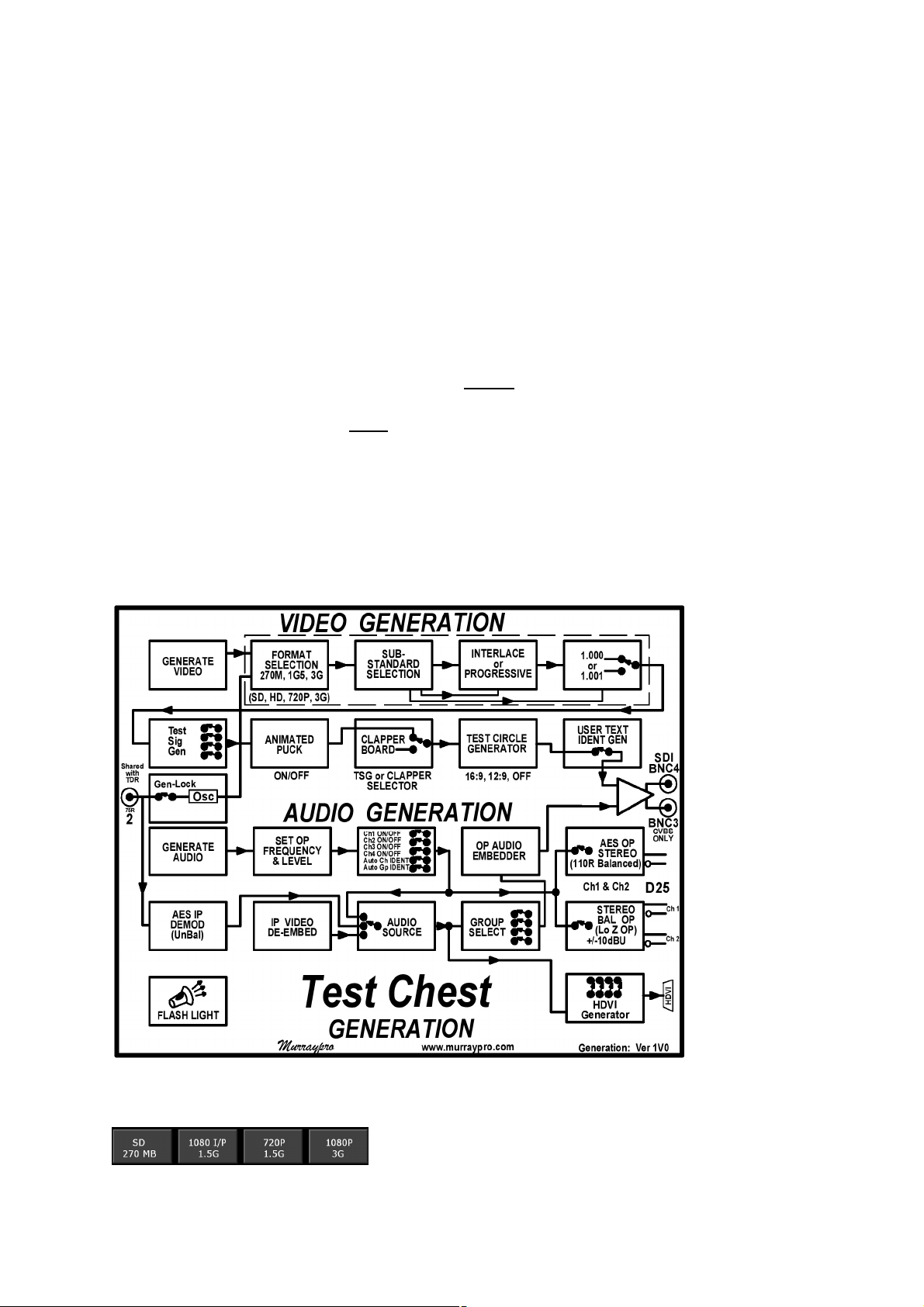
Users should be aware that some Menu options, although subtle, will
substantially alter the mode of operation. As may be appreciated from
the Test Chest’s “Video Generation” flow chart, selecting 'Clapper
Board' for example, will bypass most other Video selections; whilst
selecting 'OUT~LOOP' bypasses the local TSG, forcing the output to be
a reclocked & equalised ‘LOOP’ of the input signal..... naturally, this can
only occur if a signal is actually present at the input!
Test Chest: Manual
Selection of one of these powerful modes, whilst quite normal, could have a
high nuisance value' if unintentional, and so the TC will helpfully flag up such an
activation with a cautionary yellow coloured icon, or legend.
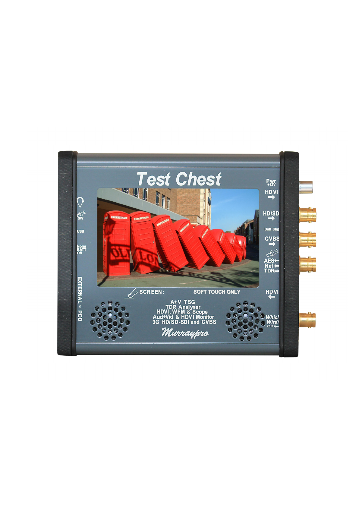
The cluster of 4 BNCs on the right side of the front panel carry Video input
and outputs. Unbalanced AES and External sync is input on BNC2, whilst the TDR
cable-test also shares this Port.
Balanced stereo audio input and output, together with the balanced AES OP,
are carried by the D-25F connector on the left panel which couples with the
“Audio~POD” breakout adapter. The 3.5mm Headphone Jack is located here too.
Test Chest: Front.
Power considerations.
Test Chest is powered when portable, from an internal 3000mAH 7V2 Lithium
Polymer battery pack. We have achieved nearly 5 hours endurance with a freshly
charged battery in tests, so realistically Users could anticipate in excess of three
hours operation. Power drain will be dependent to some extent upon LCD back light
Test Chest: Manual
brightness, the mode used, and the Clock rate of the TV Standard.
Test Chest is unusual in that it has two quite distinct modes of operation, and
these are totally different, and separate, from any battery charging considerations:-
a) In Which-Wire? mode, the unit will detect an input signal on BNC1, and
power up automatically, displaying the signal as soon as it is detected. NO action
being required from the User, other to plug the unknown source into BNC1.
In “W-W?” mode, TC will automatically power down a moment or two after the
input signal is removed from BNC1. 'Touching' the LCD panel will end the “W-W?”
mode, and manual 'power down' will be required to restore “W-W?” mode.
b) In the Generation and Measurement modes, it will be necessary to turn the
Unit ON manually. This is achieved gently tapping the LCD panel, and
CONFIRMING your 'power on' request by tapping the Switch ICON presented in the
bottom-right of the LCD. In these modes, the Test Chest is 'powered down' by briefly
tapping the YELLOW switch icon on the menu home page.
Test Chest provides essentially 9 functions, which are described
more fully later, but these are at present, perhaps, best initially
considered under 3 major separate function headings:-
Test Chest: Manual
1) Which-Wire?
Which-Wire? is an exceptionally powerful investigative tool in which Test
Chest emulates our earlier Murraypro 'Which-Wire?' Unit, and it is not even
necessary to ‘manually’ power the Unit up for operation in this mode. As soon as a
signal is applied to the 'Which-Wire?' input Test Chest automatically awakens,
determines it’s signal format, automatically selecting the optimum manner to display
the detected signal, whether it be TV monitor, WFM, or as an audio histogram.
Additionally if a TV signal is detected, it identifies the source's TV Standard as 3GSDI, HD-SDI, SD-SDI, CVBS, together with it's Frame Rate, which is reported on a
Banner at the top of the 16:9 LCD screen.
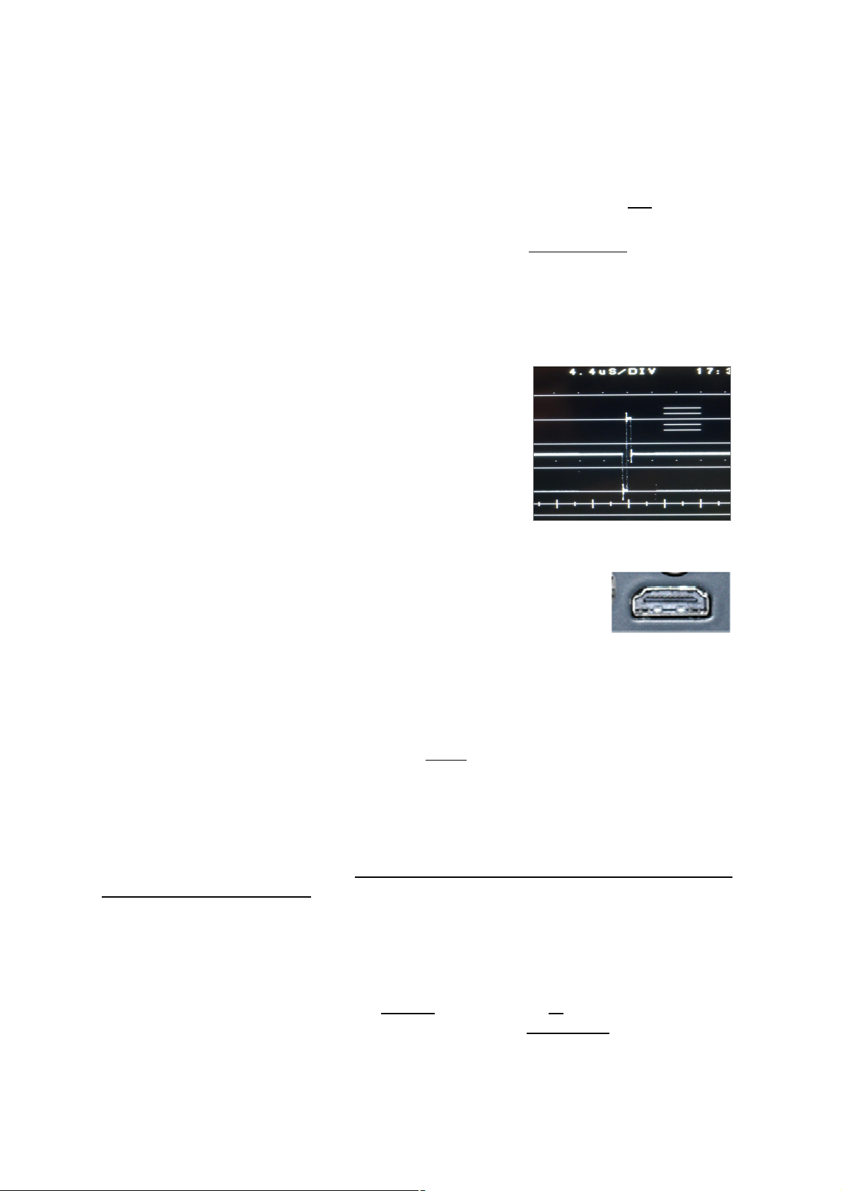
“W-W?” capability includes 'Tri-Level' and
'Colour Black' Sync detection. Either sync signal is
displayed in the WFM's 'H Expand' mode.
“W-W?” capability on BNC1 includes the
detection of UNBALANCED AES and SPDIF sources.
When present, the LCD display automatically selects
AES mode on the 'Audio Monitoring' page.
“W-W?” detection mode has been extended to now
include High Definition Video Interface sources which are applied
to the connector twixt BNC1 & 2. When detected, HDVI images
@ TV related scan rates will be displayed, sources on other
standards will be detected, but may not be coherently presented.
Users should connect their 'mystery IP signal' to the lowest BNC connector,
BNC1, designated “WW?” at the bottom right of the front panel. This connector
always terminates the input with 75W, so it is never necessary to provide a separate
external termination. The fundamental feature of Which-Wire? Mode is that CVBS,
SDI and AES signals enter the Unit via the same connector. It is never necessary to
double guess what signal may be present on a given cable, as the Test Chest will
automatically switch to the appropriate Digital, Analogue, AES or Tri-level/Composite
sync mode, as required to correctly display the detected input which now includes
HDVI signals with TV related image formats.
It is vital to appreciate that “Which-Wire?” mode can ONLY be initiated with
the Test Chest un-powered, it cannot function when the Test Chest is already
powered up as it will already be in a ‘manually’ selected operating mode!
Following a ‘manual’ power-up, the main menu is presented from which the
User selects ‘TV’, WFM’ or ‘Audio’ mode as required. ~ Let us assume ‘TV’ mode is
manually selected, so applying a TV signal to the “W-W?” input will indeed display
an immediate picture, and in fact this will be even faster than from quiescent, as the
Unit is already powered, BUT it can’t identify Tri-level sync, or AES audio for
example, nor display these in any meaningful manner in TV Monitor mode, as this
doesn’t offer any 'WFM display' or AES measurement capability!
Test Chest: Manual
This powerful “Which-Wire?” auto-detection feature is an important and vital
difference pioneered by Murraypro which completely separates Test Chest from
any other product. Other testers will require Users to consecutively, and tediously,
offer an unknown signal to the separate SDI, CVBS and AES inputs in turn; if indeed
they actually possess any analogue capability at all! Consider for a moment, just how
does one investigate and resolve a Station Reference Pulse problem without any
analogue capability?
AES inputs in “Which-Wire?” mode.
Be aware that Test Chest’s highly impressive capability of detecting and
identifying “AES” signals fed in via BNC1, ONLY applies when the Unit is in
“Which-Wire?” mode, having powered itself up automatically.
It most certainly does NOT apply when the Unit has been manually powered,
or if the “W-W?” mode has been manually over ridden with a subsequent 'touch'
command. Under these powered conditions it is necessary to apply the unbalanced
AES source directly to BNC 2, the normal AES IP port, and which is labeled as such.
Under all 'powered' modes use of BNC 2 as the AES input port is mandatory.
AES signals manually presented to the “Video” port BNC1, will NOT be recognised.
2a) Test Signal Generation ~ Video
TSG.
The Test Chest contains a powerful, high quality,
10 bit TSG that is suitable for testing TV equipment.
The TV video format, categorized by ‘Clock rate’ is selected first (1080 @ 3G, 1080
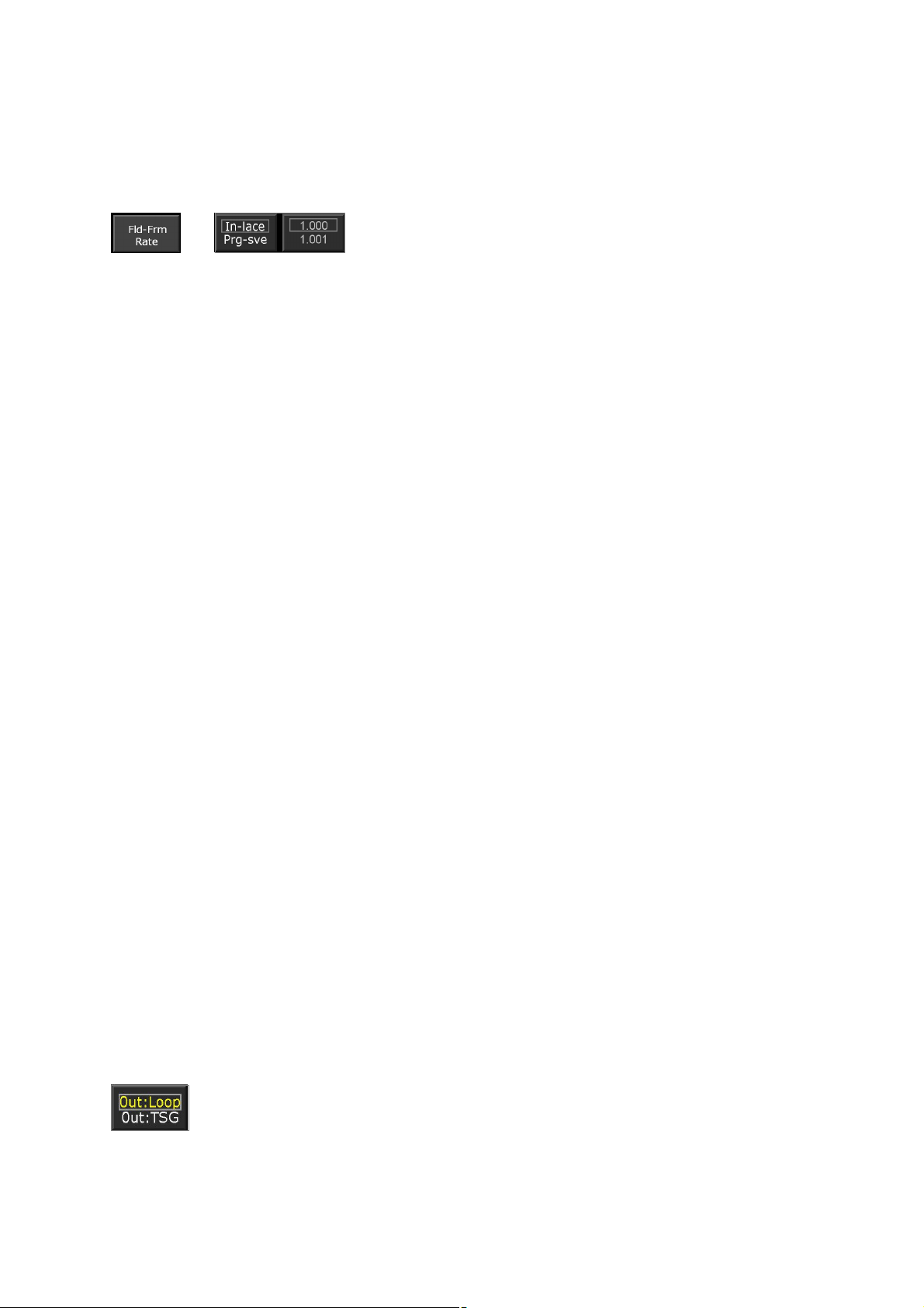
Test Chest: Manual
or 720 @ 1.5G, or SD @ 270MB), followed by the required Frame rate (24, 25, 30,
50 or 60Hz), and on 60Hz related standards, subsequent sub-selection between
1.000 & 1.001 rates. On non-progressive only standards, interlace may be selected.
Support for Level B Dual Link at 3G is provided.
Menu selection of the different Test signals is easy
and intuitive, with the Generator providing parallel SDI
and CVBS outputs of the selected Test Signal on SD.
Tri-level sync generation.
The CVBS video output can of course only be valid whilst the Test Chest is
generating at 'Standard Definition' on 525 or 625 Standards, and is muted on HD.
However on all high definition standards BNC 3 will output Tri-level syncs, and this
changeover is completely automatic and transparent.
Tri-level syncs may be looped from BNC 3 round to BNC 2, and then used as
an external reference for the Wave Form Monitor; this will particularly useful when
Test Chest is used to measure ‘Latency’ through digital equipment.
HDVI Signal generation.
Test Chest contains two HDVI ports using industry standard connectors
and suitable for use with commercially available, or pre-installed HDMI cables; one
each for input and output and both are independently available whilst the system is
powered. A digital DVI OP is available via a proprietary passive HDMI/DVI adapter.
These signals are primarily intended for use in Television based
Engineering applications, rather than ‘Multi-Media’ entertainment environments. So
although industry standard connectors are used for convenience, the generation and
display capability is pitched towards confirmation of function with SD and HD
Professional TV related display standards, and a non-exhaustive list of the generally
TV related Graphics standards that can be coherently displayed is tabulated in the
Specification section.
HDVI signals generated by Test Chest may be selected from either a
dedicated TSG or the LCD panel’s screen, and in either case the OP standard is
800x640. Either source may be used as a convenient HDVI stream for quickly
checking connectivity or system function, and neither are intended for detailed
system analysis purposes although elements of ‘681 are supported.
Unlike some other Generators producing a PC/Graphics output, the
signals produced by Test Chest’s separate Graphics TSG do not stray from ‘legal
values’.
If required, Test Chest can generate a separate SPDIF compatible audio
output too from the AES OP stream, via the Audio-POD’s integral BAL/UN matching
transformer.
Input looping ~ ‘Processing Amplifier’ mode.
SDI Equalisation and reclocking:
Using the Home Menu it is practical to “LOOP” external SDI signals
through the Unit and benefit from the internal equalisation and re-clocking
facility. Note that the menu flags this unusual setting with yellow text.
CVBS looping:
Test Chest will also loop CVBS inputs. CVBS will be ac coupled to remove any
Test Chest: Manual
possible dc off–set on the input, and then clamped to remove dc changes due to
variations with Average Picture Level.
Text Ident:
A locally generated identification text string may be inserted into the
output video, a particularly useful feature when identifying long lines. The
Character Generator's non-volatile memory is pre-loaded with “TESTCHEST” when shipped; however it is very easily reprogrammed to individual
requirements by using the Text menu provided, an operation familiar to all mobile
phone Users.
External video Reference:
TC may be Gen-locked (Slaved) to an external video Reference, this
allows the output signal to be ‘timed’ to a Vision Mixer, for example.
The external reference is applied as either a Composite video, Composite
or Tri-Level sync to BNC2. Selection between modes is via menu icon. Be aware
that Mixed or Composite sync is only appropriate for SD, and that HD standards
require Tri-level syncs.
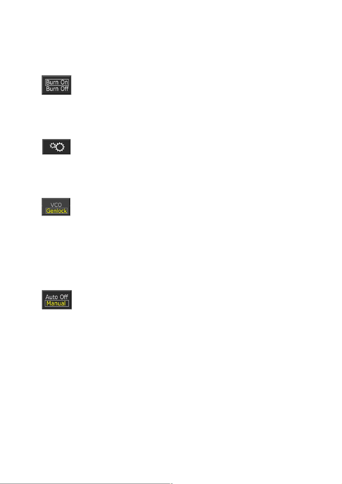
Genlock operation is initiated via the main menu's “Gear” icon, which
leads to the Set-Up sub-menu page. The TSG output will be maintained
locked within ½TV line of the Reference, enabling fully synchronous
operation with digital equipment employing 2H digital synchronisers.
Backlight:
Once the TSG mode has been set up, one may wish to reduce the LCD's
back light drive to a lower brightness. Using the 'Set Up' menu the brilliance may be
reduced, or switched to 'LCD DIM' mode to conserve battery power.
Auto/Manual Power Management:
Under certain circumstances it may be desired to set the Test Chest to
generate a test signal for a prolonged period, perhaps whilst tests are
performed elsewhere.
If no icon 'activation' is detected for 10 minutes, in ‘Auto off’ mode the Unit will
automatically shut down to conserve battery power.
This time-out may be defeated by selecting 'Always ON' in the main menu. Be
aware however that when running on battery power, the Unit will continue to operate
until the battery’s low voltage cut off logic activates. No Li-Po battery distress will
occur, but the Unit will not be capable of further battery powered operation until the
battery is recharged.
Murraypro recommend that the battery is recharged as soon as possible.
Test Chest may be used, and will continue to operate normally whilst it's
battery is being recharged. Charge completion is indicated by the extinguishing of
the yellow LED twixt BNC 3 & 4.
It is not necessary to remove the low voltage lead when charging is
completed, and Test Chest may be safely run for protracted periods with the
‘charge/external power’ lead connected.
Test Chest: Manual
2b) Test Signal Generation~Audio
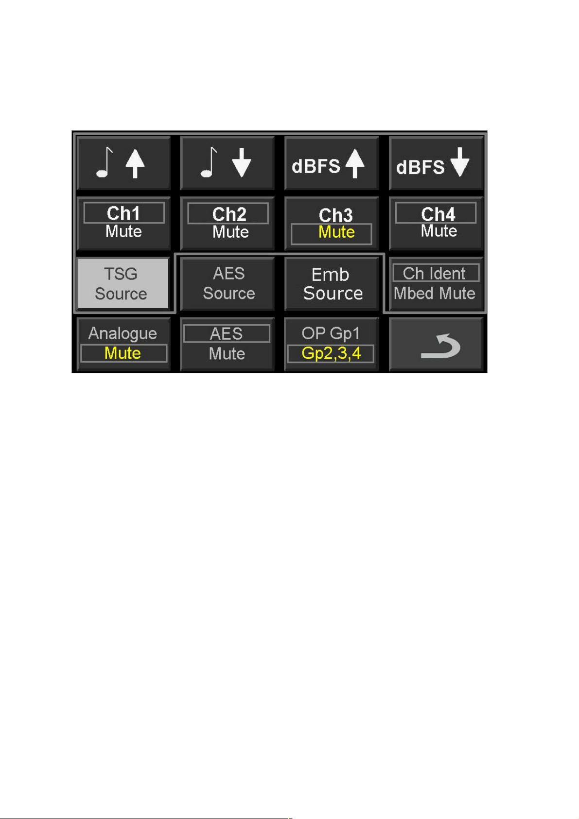
Test Chest generates audio in 3 different formats simultaneously:-
1) Embedded Audio is inserted in Group 1 by default, but Group 2, 3 or 4 may be
manually selected for instead. Each channel 1~4 within the selected Group
may be enabled or muted as required, with on-screen mapping to track and
display the current set up.
Audio modulation may be muted to ‘Digital Silence’. This does not affect the
digital house-keeping data, which is always generated.
2) AES output stream. This is enabled by default and runs in parallel with and
uses the same source as Embedded Audio, via the 'Generate Audio' page.
Channels 1 or 2 may be enabled, or muted as required.
The Unit’s dual channel AES output is presented on the D-25F
connector as an 110W balanced 48KHz AES encoded stream. This output
port is automatically coupled through to the Audio-POD when it is connected;
and it is accessed via the AES OP XLR3-M.
For Un-Balanced 75W AES operation, the balanced OP should be first
routed to the BAL/UN (110W:75W) transformer on the Audio-POD, and then
extended to the load from the POD's unbalanced AES 75 W BNC as usual.
3) Balanced dual channel analogue audio. Enable this mode which runs in
parallel with, and uses the same source as Embedded Audio, via the
'Generate Audio' page and, as with the Embedded Audio, Channels 1 or 2
may be enabled, or muted, as required.
The Unit's dual channel Analogue output is also presented on the D-
25F connector, and these low impedance balanced output ports are also
conveniently coupled through to the Audio-POD, where it is accessed via the
Analogue OP's dual XLR3-Ms.
Test Chest: Manual
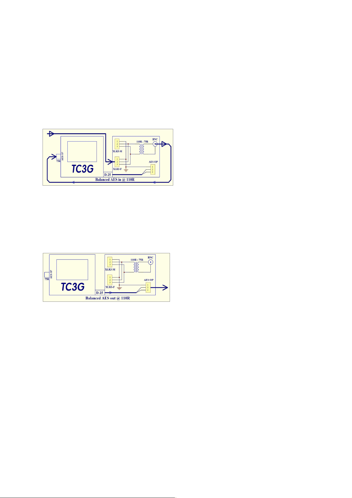
AES Matching with the Audio POD:
Generation & Monitoring
AES: Unbalanced IP @ 75 W.
Very easy, just couple the coax cable to BNC2 Test Chest’s main AES input.
AES: Balanced IN on XLR3-M @ 110W.
Couple IP cable XLR3-M to the POD’s
Transformer XLR3-F, and loop a short
BNC~BNC coax round to TC’s BNC2.
AES: Balanced OP @ 110RW.
Very easy! Just connect your XLR3-F cable to the POD’s AES OP.
AES: Unbalanced OP @ 75W.
Use an XLR~XLR ‘double ender’, couple
the POD’s XLR3-M AES OP back into
the POD’s transformer, and then plug
your coax cable into the POD’s 75W
BNC.
Output amplitude considerations:
The Embedded and AES digital audio bit-streams may be operated over a
much greater encoded amplitude range than that of the balanced analogue audio,
where practical considerations confines Test Chest’s limits to about +/-10dBU.
Do not confuse the encoded audio amplitude data with the actual amplitude of
the AES bit stream which remains unaltered, at around RS422 levels; normally
around 3~4 V PP.
Digital outputs may be adjusted in 1dB steps from 0dBFS down to -80dBFS.
This low output amplitude is useful for testing the digital microphone inputs of a
Mixer realistically. Whilst the overall envelope of the AES signal will remain at the
standard RS422 level at all times, digital microphones usually emulate their
analogue partners' low OP level, generating an AES output with a similar low digital
modulation amplitude.
Analogue amplitude:
The analogue audio channel is aligned such that a level of “-18dBFS” will
Test Chest: Manual
produce a balanced analogue OP of 0.775VRMS = 0dBU, this is about 10dB below
the maximum OP. Users are reminded that the maximum balanced analogue output,
which does embrace the normal +8dBU peak programme level, is headroom-limited
by the internal battery voltage to about +10dBU.
Murraypro recommend using an external 60dB XLR/XLR attenuator if it is
desired to simulate 'Mic level' and similar low level analogue signals.
Audio Sources:
1) The internal audio oscillator offers menu selected spot frequencies, and
amplitudes.
2) An External AES input may be selected. Be aware that, although a 48KHz
source may easily be monitored and metered, it will not be practical to use it
as an Embedded source, unless the 48KHz input Word Clock is synchronous
with the output Video signal.
3) External Embedded Audio may be selected that has been extracted from the
signal applied to BNC1, the “Which-Wire?” input. Be aware that, as above,
unless the 48KHz input Word Clock is synchronous with the output Video
signal, it will not be possible to use it as an Embedded source.
4) TC3G offers a very powerful Utility in the “Audio Measurement” menu, which
indicates whether an external AES input signal is synchronous with a video
reference that is applied via the WW? Operation is described under the
following “AES/Video Lock Confirmation” passage.
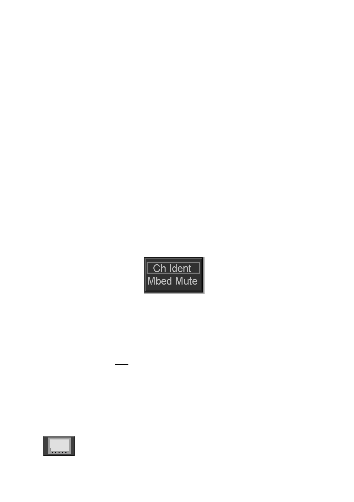
5) A unique pulsed 'Tone PIP' identification can be added by TC3G to each
audio channel within a selected Group. This enables downstream monitoring
points to correctly, and unambiguously, identify each channel individually.
600
W
Audio loading:
Output loading: Test Chest follows current audio line driving practice, sending
from a current limited, balanced, low impedance source.
Test Chest follows Broadcast equipment’s input convention, by presenting a
balanced load with a high impedance comfortably in excess of 10KW.
600W loads are very unusual with current audio practice, and the significant
loading of the XLR3-M balanced output by a 600W termination will cause a reduction
in the output amplitude of perhaps a couple of dB, by potential divider action.
The outputs are current limited, and no damage will occur due to short circuits
or indeed 600W loading.
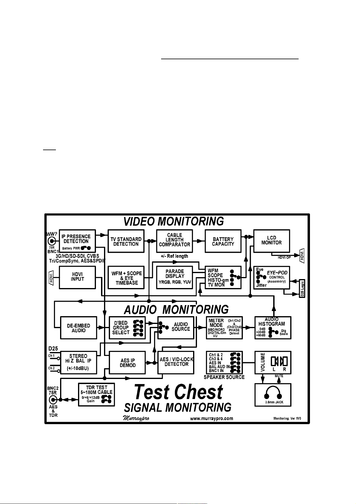
3) A&V Monitoring
TV Monitor:
TC3G incorporates a TV Monitor function with 800 x 480 pixel resolution
which automatically displays images in any supported Format.
 Loading...