

Page 1
Not for
Reproduction
Parts Manual
Models
Mfg. No. Description
7800864 EM2045, 4.5GT 20" Walk Behind Mower, CE (2012)
7800888 MD20450FC, 4.5GT 20" Walk Behind Mower, CE (2012)
Walk Behind Mower
Manual Part No. 1754788
Revision
Rev. Date:
3/5/2012
-
Page 2

Not for
Reproduction
Page 3

Not for
Reproduction
Table Of Content
s
PRODUCT COMPONENTS PAGES
Handle Assembly .................................................................................................................................................
Deck & Engine Group ..........................................................................................................................................
Decal Group .........................................................................................................................................................
Torque Specification Chart ..................................................................... Inside Back Cover
4
6
8
Page 4
Not for
Reproduction
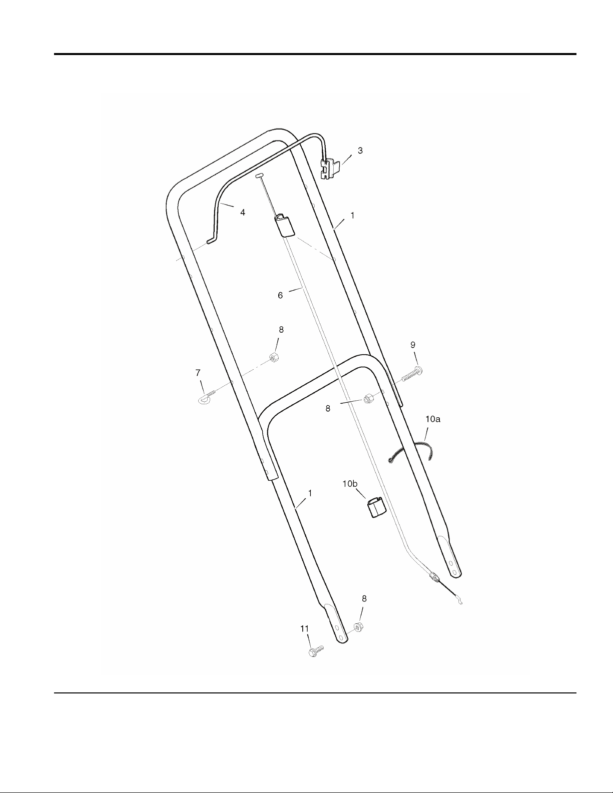
Handle Assembly
NOTE: Unless noted otherwise,
use the standard hardware torque
specification chart.
7800711ha
The above parts group applies to the following Mfg. Nos.:
7800864 - EM2045
7800888 - MD20450FC
© Copyright by Briggs & Stratton Corporation
Milwaukee, WI, USA. All rights reserved
2012
4
1754788
Page 5

Not for
Reproduction
Handle Assembly
PART NO. DESCRIPTIONREF NO QTY.
HANDLE 1 7301150AYP 2
BRACKET, Stop Lever 3 1101454E701MA 1
LEVER, Stop 4 7104326AYP 1
CABLE, Stop 6 1101093MA 1
GUIDE, Rope 7 043956MA 1
NUT, Hex Nylock, 1/4-20 8 1908125MA 9
BOLT, Carriage, Short Neck, 1/4-20 x 1-3/8 9 7090947YP 4
WIRE TIE, 5.5" 10a 7024641YP 2
CLIP, CABLE 10b 1101352MA 1
BOLT, Carriage, Short Neck, 1/4-20 x 3/4, G5 11 1931317SM 4
Footnotes
The above parts group applies to the following Mfg. Nos.:
7800864 - EM2045
7800888 - MD20450FC
© Copyright by Briggs & Stratton Corporation
Milwaukee, WI, USA. All rights reserved
2012
5
1754788
Page 6

Not for
Reproduction
Deck & Engine Group
NOTE: Unless noted otherwise,
use the standard hardware torque
specification chart.
7800711dk
The above parts group applies to the following Mfg. Nos.:
7800864 - EM2045
7800888 - MD20450FC
© Copyright by Briggs & Stratton Corporation
Milwaukee, WI, USA. All rights reserved
2012
6
1754788
Page 7

Not for
Reproduction
Deck & Engine Group
PART NO. DESCRIPTIONREF NO QTY.
1 09T502-3121-H1 1
1 09L602-0110-F1 1
* ENGINE, 450 Series, Briggs & Stratton (Engine Model: 09T502-0121-B1) (Used on
EM2045)
* ENGINE, 450 Series, Briggs & Stratton (Engine Model: 09L602-0110-F1) (Used on
MD20450FC)
HOUSING, 20" 2 ----- 1
CAPSCREW, Hex Washer Head, Self Tap, 3/8C x 1 3 7090324SM 3
BOLT, Shoulder, 3/8-16 x 2 4 009X10MA 4
WHEEL, 6 x 1.50 (Used on EM2045) 5 7101738YP 4
WHEEL, 7 x 1.50 (Used On MD20450FC) 5 7102068YP 4
WASHER, Flat, 3/8 6 17X168ZMA 4
CAPSCREW, Hex Washer Head, SEMS, #10 x 1/2 7 26X245MA 2
EXTENSION 8 7300714YP 1
GUARD, Rear 9 671912MA 1
BOLT, Hex, 1/4-20 x 3/4 10 01X121MA 2
WASHER, 1/4 11 017X37MA 2
NUT, Hex Nylock, 1/4-20 13 1908125MA 2
DEFLECTOR 14 671929MA 1
ADAPTER, Blade 15 071056MA 1
BLADE, 20" 16 042785E701MA 1
WASHER, Blade 17 17X137MA 2
WASHER, 3/8 18 1918266SM 1
BOLT, Hex, 3/8-24 x 1-1/2 19 01X142MA 1
NUT, Hex Flange, Serrated, 3/8-16 20 1499MA 4
WASHER, Plain, .40 21 17X191MA 1
Footnotes
Note* To verify your specific engine model, please reference the ID Tag located on your engine. See your local Briggs &
Stratton distributor for parts and service.
The above parts group applies to the following Mfg. Nos.:
7800864 - EM2045
7800888 - MD20450FC
© Copyright by Briggs & Stratton Corporation
Milwaukee, WI, USA. All rights reserved
2012
7
1754788
Page 8

Not for
Reproduction
Decal Group
NOTE: Unless noted otherwise,
use the standard hardware torque
specification chart.
7800864dcl
The above parts group applies to the following Mfg. Nos.:
7800864 - EM2045
7800888 - MD20450FC
© Copyright by Briggs & Stratton Corporation
Milwaukee, WI, USA. All rights reserved
2012
8
1754788
Page 9

Not for
Reproduction
Decal Group
PART NO. DESCRIPTIONREF NO QTY.
DECAL, OPC BAIL 1 7029782MA 1
DECAL, 450 Series 2 7104063YP 1
DECAL, Logo, Deck (Used on EM2045) 3 7102124YP 1
DECAL, Logo, Deck (Used on MD2045FC) 3 7102124YP 1
DECAL, Warning, Multi Panel (Used on EM2045) 4 7101084YP 1
DECAL, CPSC, FR / NG (Used on MD2045FC) 5 7101495YP 1
DECAL, Danger, FR / ENG (Used on MD2045FC) 6 7103405YP 1
DECAL, Warning, FR / ENG (Used on MD2045FC) 7 7103406YP 1
Footnotes
The above parts group applies to the following Mfg. Nos.:
7800864 - EM2045
7800888 - MD20450FC
© Copyright by Briggs & Stratton Corporation
Milwaukee, WI, USA. All rights reserved
2012
9
1754788
Page 10

Not for
Reproduction
Page 11

Not for
Reproduction
Hardware Identification & Torque Specifications
No
Marks
0
1/4 3/4
1/2
21
1/4 3/4
1/2
1/4 3/4
1/2
1/4 3/4
1/2
4
Torque Specification Chart
FOR STANDARD METRIC MACHINE HARDWARE (Tolerance ± 20%)
Property
Class
Size Of
Hardware
M3
M4
M5
M6 7.3 10.3 12.1
M7 12.1 16.9 19.9
M8 17.7
M10 35 50
M12 61 86.2 103 140
M14
M16 147 210 250 340
M18 202 287 346 470
M20 290 405 486 660
M22 390 559 656 890
M24 497
M27 733 1032 1239 1680
M30 995 1401 1681 2280
M33
M36 1740 2441
M39 2249 3163
The guides and ruler furnished below are designed to
help you select the appropriate hardware.
010
Nut, M8
Thread
Diameter (mm)
Inside
Diameter (in)
Nut, 1/2-16
Class 5.6
in/lbs
ft/lbs
5.88
13.44
26.4
44.64
5.2
7.7
15
26
42
64
89
126
169
217
320
435
590
759
988
20
5.6
Nm. Nm. Nm.
.56
1.28
2.50
4.3
7.1
10.5
21
36
58
88
121
171
230
295
435
590
800
1030
1340
30
8.8
Class 8.8
in/lbs
ft/lbs
13.44 1.80
30.72 43.44 52.56
60.96
Class 10.9
in/lbs
ft/lbs
19.2 22.92
1.28
2.90
5.97 7.15
5.75
9.9
16.5
24
48
83
101
136 162 220
132
200
275
390
530
708
375
995
1350
1349
1902 2278 3090
1830
2360
3050
50
60
Body Length
40
Screw, M8- 1.25 x 25
Thread
Diameter (mm)
Threads
per inch
Body
Diameter
Screw, 1/2- 16 x 2
10.9
4.10
8.10
14
23
25
34
67
117
185
285
390
550
745
960
1400
1900
2580
3310
4290
80
Diameter
Distance between
threads (mm)
Threads
per inch
3
12.9
Class 12.9
in/lbs
ft/lbs
29
59
840 1140
2935 3980
3798
Body
Nm.
2.15
4.95
9.7
16.5
27
40
81
5150
90 10070
Body
Length (mm)
Body
Length (in)
Torque Specification Chart
FOR STANDARD MACHINE HARDWARE (Tolerance ± 20%)
Hardware
Grade
Size Of
Hardware ft/lbs Nm. ft/lbs Nm. ft/lbs Nm.
8-32
8-36
10-24
10-32
1/4-20
1/4-28
5/16-18 11 15.0 17 23.1 25 34.0
5/16-24 12 16.3 19 25.8 29 34.0
3/8-16 20 27.2 30 40.8 45 61.2
3/8-24 23 31.3 35 47.6 50 68.0
7/16-14 30 40.8 50 68.0 70 95.2
7/16-20 35 47.6 55 74.8 80 108.8
1/2-13 50 68.0 75 102.0 110 149.6
1/2-20 55 74.8 90 122.4 120 163.2
9/16-12 65 88.4 110 149.6 150 204.0
9/16-18 75 102.0 120 163.2 170 231.2
5/8-11 90 122.4 150 204.0 220 299.2
5/8-18 100 136 180 244.8 240 326.4
3/4-10 160 217.6 260 353.6 386 525.0
3/4-16 180 244.8 300 408.0 420 571.2
7/8-9 140 190.4 400 544.0 600 816.0
7/8-14 155 210.8 440 598.4 660 897.6
1-8 220 299.2 580 788.8 900 1,244.0
1-12 240 326.4 640 870.4 1,000 1,360.0
1. These torque values are to be used for all hardware
excluding: locknuts, self-tapping screws, thread forming
screws, sheet metal screws and socket head setscrews.
2. Recommended seating torque values for locknuts:
a. for prevailing torque locknuts - use 65% of grade 5
b. for flange whizlock nuts and screws - use 135% of
3. Unless otherwise noted on assembly drawings, all torque
values must meet this specification.
Common Hardware Types
Hex Head Capscrew
SAE Grade 2 SAE Grade 5 SAE Grade 8
in/lbs in/lbs
19
2.1
20
2.3
27
3.1
31
3.5
66
7.6 8 10.9 12 16.3
76
8.6 10 13.6 14 19.0
30
31
43
49
in/lbs
3.4
3.5
4.9
5.5
NOTES
torques.
grade 5 torques.
41
43
60
68
Washer
4.6
4.9
6.8
7.7
Standard Hardware Sizing
When a washer or nut is identified as 1/2” (M8), this is
Nominal size
the
(8mm metric thread diameter); if a second number is present
it represents the
When bolt or capscrew is identified as 1/2 - 16 x 2” (M8 - 1.25 x 50 ),
this means the
metric thread diameter), the second number,16, represents the
threads per inch, (1.25 thread diameter).
body length of the bolt or screw, 2 inches (50mm).
, meaning the
threads per inch
Nominal size
inside diameter
is 1/2 inch
(distance between threads).
, or body diameter is 1/2 inch (8mm
The final number is the
Carriage Bolt
Wrench & Fastener Size Guide
1/4” Bolt or Nut
Wrench—7/16”
M6 Bolt or Nut
Wrench—10mm
5/16” Bolt or Nut
Wrench—1/2”
M8 Bolt or Nut
Wrench—13mm
3/8” Bolt or Nut
Wrench—9/16”
M10 Bolt or Nut
Wrench—17mm
7/16” Bolt or Nut
Wrench (Bolt)—5/8”
Wrench (Nut)—11/16”
M12 Bolt or Nut
Wrench—19mm
Lockwasher
Hex Nut
1/2” Bolt or Nut
Wrench—3/4”
M14 Bolt or Nut
Wrench—22 mm
Page 12

Not for
Reproduction
IT IS THE POLICY OF BRIGGS & STRATTON CORP. TO IMPROVE ITS PRODUCTS
WHENEVER IT IS POSSIBLE AND PRACTICAL TO DO SO. WE RESERVE THE RIGHT TO
MAKE CHANGES OR ADD IMPROVEMENTS AT ANY TIME WITHOUT INCURRING ANY
OBLIGATION TO MAKE SUCH CHANGES ON PRODUCTS.
Briggs & Stratton Power Products Group
12301 W. Wirth Street
Wauwatosa, WI, 53222 USA
www.BRIGGSandSTRATTON.com
www.murray.com
© Copyright by Briggs & Stratton Corporation
Milwaukee, WI, USA. All rights reserved
2012
 Loading...