

Page 1
Instruction Book Snow Thrower Model 624804X31
Manuel d'instructions chasse-neige modèle 624804X31
Read and keep this book for future reference. This book contains important information on
AND MAINTENANCE.
Lisez et conservez ce manuel pour référence. Ce manuel contient des informations importantes
concernant la
SECURITE, LE MONTAGE, L’UTILISATION ET L’ENTRETIEN.
SAFETY, ASSEMBLY, OPERATION,
F–001043J 10/22/99
Page 2
NOTE: This unit is equipped with an internal combustion engine
and must not be used on or near any unimproved
forest–covered, brush–covered or grass–covered land unless
the engine’s exhaust system is equipped with a spark arrester
meeting applicable local or state laws (if any). If a spark arrester
is used, it must be maintained in effective working order by the
operator.
In the State of California, the above is required by law (Section
4442 of the California Public Resources Code). Other states
may have similar laws. Federal laws apply on federal lands. See
an Authorized Service Center for a spark arrester for the
muffler.
REMARQUE : cette machine est équipée d’un moteur à
combustion interne et ne doit pas être utilisée sur un terrain
forestier, buissonnant ou herbeux non préparé, à moins que le
dispositif d’échappement soit pourvu d’un pare–étincelles
conforme à la législation locale ou de l’état (le cas échéant). Si
un pare–étincelles est utilisé, celui–ci doit être maintenu en
parfait état de fonctionnement par l’utilisateur.
Au sein de l’état de Californie, la loi exige la prise en compte
des précautions mentionnées ci–dessus (clause 4442 du
California Public Resources Code). D’autres états peuvent
présenter des lois similaires. Les lois fédérales s’appliquent sur
les terres fédérales. S’adresser à un centre de maintenance
agréé pour l’achat d’un pare–étincelles pour l’échappement.
The engine exhaust from this product
contains chemicals known to the State
of California to cause cancer, birth
defects or other reproductive harm.
Le système d’échappement de cette
unité contient des substances
chimiques, qui selon l’État de
Californie, peut causer le cancer, des
malformations à la naissance, ou un
danger pour la reproduction.
F–001043J
2
Page 3
1
10
9
8
11
5
6
2
1
2
18
2
14
13
1
7
12
16
157
3
2
1
3
9
7 (71037)
1
5 (71071)
4 (6751)
12
15
13
3
4
4
11
10
6 (71060)
17
5
2
1
4
3
7
6
5
14
16
6
F–001043J
3
Page 4
7
8
2
1
1
2
1
2
9 10
6
6
78
3
1
1
3
3
4
1
1
1
2
2
5
11 12
1
6
5
4
1
2
3
7
8
6
F–001043J
4
Page 5
13
14
13
1
2
12
3
15
15
6
5
4
9
10
2
11
1
2
16
8
4
17
2
4
3
5
3
18
5
4
F–001043J
7
5
3”
7.62cm
Page 6
19
5
8
1
6
4
20
9
8
4
21
2
3
4
F–001043J
6
Page 7

22
1– 6751
2– 9524
1– 71060
2– 3943
1– 71071
2 – 73826
1– 71037
1– 6219
F–001043J
7
Page 8

CONTENTS
PRODUCT INFORMATION 8
OWNER’S INFORMATION 8
INTERNATIONAL PICTORIALS 9
ASSEMBLY 11
OPERATION 11
MAINTENANCE 14
MAINTENANCE CHART 14
TROUBLE SHOOTING CHART 17
TWO YEAR LIMITED WARRANTY
Murray, Inc. warrants to the original purchaser
that this unit shall be free from defects in
material and workmanship under normal use
and service for a period of Two (2) Year from
the date of purchase; however, this warranty
does not cover engines, accessories (such as
electric starters) and Normal Wear Parts (except
as noted below) as the companies that
manufacture these items furnish their own
warranties and provide service through their
authorized field service facilities. For additional
information, see the warranties covering these
particular parts. If you are uncertain whether
your unit contains or is equipped with one or
more of these parts, consult your dealer prior to
purchase. Subject to the terms and conditions
noted in this Limited Warranty, we shall, at our
option, repair or replace at no cost to the original
purchaser any part covered by this Limited
Warranty during the applicable warranty period.
Normal Wear Parts are defined as drive belts,
augers, shear pins, tires and headlights. These
parts are warranted to be free from defects in
material and workmanship as delivered with the
product. Any claim for repair or replacement of
Normal Wear Parts must be made within thirty
(30) days of the date of purchase. No claims
involving damage caused from material use,
abuse or misuse will be honored.
This Murray, Inc. Two (2) Year Limited
Warranty is your exclusive remedy; however,
this warranty is void or does not apply to any
unit that has been tampered with, altered,
misused, abused or used for rental or other
commercial and/or professional
(non–homeowner) uses. Your warranty does not
cover minor mechanical adjustments which are
not due to any defect in material or
workmanship. For assistance in making such
adjustments, consult your Instruction Book.
To make a claim under this Murray, Inc. Two (2)
ENGLISH
Year Limited Warranty, return the unit (or if
authorized in advance, the defective part) along
with your proof of purchase to an Authorized
Service Center near you. To locate the nearest
Authorized Service Center, call the Central Parts
Distributor for your area shown in the list
provided with your unit or check the Yellow Page
listings in your local telephone directory. If you
return the entire unit, we will repair the unit. If we
authorize the return of the defective part only, we
will either replace or repair the part.This Murray,
Inc. Two (2) Year Limited Warranty gives you
specific legal rights, and you may also have
other rights which vary from state to state. This
Limited Warranty is given in lieu of all other
expressed and implied warranties including
the implied warranty of merchantability and
warranty of fitness for a particular purpose. If
you need additional information on this written
warranty or assistance in obtaining service,
write:
MURRAY, INC.
Outdoor Power Equipment
Customer Service Department
P.O. Box 268
Brentwood, Tennessee 37027
1–800–251–8007
PRODUCT INFORMATION
The owner must be certain that all the product
information is included with the unit. This
information includes the INSTRUCTION
BOOKS, the REPLACEMENT PARTS and the
WARRANTIES. This information must be
included to make sure state laws and other laws
are followed.
OWNER’S INFORMATION
This instruction book is written for a person with
some mechanical ability. Like most service
books, not all the steps are described. Steps on
how to loosen or tighten fasteners are steps
anyone can follow with some mechanical ability.
Read and follow these instructions before you
use the unit.
Know your product: If you understand the unit
and how the unit operates, you will get the best
performance. As you read this manual, compare
the illustrations to the unit. Learn the location
and the function of the controls. To help prevent
an accident, follow the operating instructions
and the safety rules. Keep this manual for future
reference.
IMPORTANT: Many units are not assembled
and are sold in cartons. It is the responsibility of
the owner to make sure the assembly instructions in this manual are exactly followed. Other
units are purchased in an assembled condition.
On assembled units, it is the responsibility of the
owner to make sure the unit is correctly assembled. The owner must carefully check the
unit according to the instructions in this manual
before it is first used.
WARNING: Look for this symbol to indicate
important safety precautions. This symbol
indicates: “Attention! Become Alert! Your
Safety Is At Risk.”
Responsibility Of The Owner
The responsibility of the owner is to
follow the instructions below.
1. Carefully read and follow the rules for safe
operation.
2. Follow all the assembly and preparation
instructions.
3. Inspect the unit.
4. Make sure that the operator of the unit
knows how to correctly use all standard
and accessory equipment.
5. Operate the unit only with guards, shields,
and other safety items in place and working
correctly.
6. Correctly adjust the unit.
7. Service the unit only with authorized or approved replacement parts.
8. Complete all maintenance on the unit.
Environmental Awareness
Do not fill the engine’s fuel tank completely
full.
Drain fuel for off–season storage.
Use only unleaded gasoline.
Service the air cleaner regularly.
Change oil regularly. Use 5W–30 oil.
Tune–up the engine regularly.
Keep equipment in efficient operating
condition.
Dispose of used engine oil properly.
F–001043J
8
Page 9
INTERNATIONAL PICTORIALS
IMPORTANT: The following pictorials are located on your unit or on literature supplied
with the product. Before you operate the
unit, learn and understand the purpose for
each pictorial.
ENGLISH
Safety Warning Symbols
DANGER
Thrown Objects.
Keep Bystanders Away.
WARNING
Hot Surface
DANGER
Thrown Objects.
Keep Bystanders Away.
STOP
WARNING
DANGER
Stop The Engine
Before Unclogging
Discharge Chute!
IMPORTANT
Read Owner’s Manual
Before Operating
This Machine.
Control And Operating Symbols
Slow Fast Electric Start Engine Start Engine Run
DANGER
Avoid Injury From
Rotating Auger. Keep
Hands, Feet And
Clothing Away.
Engine Off
23
Engine Stop On Choke Off Choke On
Reverse
Push To Engage
Electric Starter
Discharge LEFT Discharge RIGHT
KGS
Throttle Primer Button Ignition Key Ignition Off Ignition On
Engage
Auger Clutch Auger Collector
Drive Clutch
KGS
Fuel Oil Fuel Oil Mixture
N
Neutral
Discharge DOWN Discharge UP
Forward
Weight Transfer
Lift Handle To Engage
F–001043J
Weight Transfer
Depress Pedal To Disengage
Transmission
Insert To Run, Pull Out To Stop.
Ignition Key
9
Page 10

Safe Operation Practices for Snow Throwers
As Recommended By: American National Standards Institute.
ENGLISH
IMPORTANT: Safety standards require operator
presence controls to minimize the risk of injury.
Your snow thrower is equipped with such controls. Do not attempt to defeat the function of the
operator presence control under any circumstances.
Training
1. Read the operating and service ins t ruct ion
manual carefully. Be thoroughly familiar with
the controls and the proper use of the equipment. Know how to stop the unit and disengage the controls quickly.
2. Never allow children to operate the equipment. Never allow adults to operate the
equipment without proper instruc t ion.
3. Keep the area of operation clear of all per sons, particularly small children and pets.
4. Exercise caution to avoid slipping or falling
especially when operating in reverse.
Preparation
1. Thoroughly inspect the area where the equipment is to be used and remove all doorm at s,
sleds, boards, wires, and other foreign objects.
2. Disengage all clutches before start ing the engine (motor).
3. Do not operate the equipment wit hout wear ing adequate winter outer garments. Wear
footwear that will improve foot ing on slippery
surfaces.
4. Handle fuel with care; it is highly flam mable.
a. Use an approved fuel container.
b. Never remove fuel tank cap or add fuel to
a running engine (motor) or hot engine
(motor).
c. Fill fuel tank outdoors with extreme care.
Never fill fuel tank indoors.
d. Replace fuel cap securely and wipe up
spilled fuel.
e. Never store fuel or snow thrower with fuel
in the tank inside of a building where
fumes may reach an open flame or spark.
f. Check fuel supply before each use, allow-
ing space for expansion as the heat of the
engine (motor) and/or sun can cause fuel
to expand.
5. For all units with electric starting motors use
electric starting extension cords certified
CSA/UL. Use only with a receptac le that has
been installed in acc ordanc e with local inspection authorities.
6. Adjust the snow thrower height to clear gravel
or crushed rock surfac e.
7. Never attempt to mak e any adjus tm ents
while the engine (motor) is running (except
when specifically recommended by manuf ac turer).
8. Let engine (motor) and snow thrower adjust
to outdoor temperatures before st art ing to
clear snow.
9. Always wear safety glas s es or eye shields
during operation or while perform ing an adjustment or repair to protect eyes from foreign
objects that may be thrown from the snow
thrower.
Operation
1. Do not operate this machine if you are taking
drugs or other medication which can caus e
drowsiness or affect your ability to operate
this machine.
2. Do not use this machine if you are mentally
or physically unable to operate this mac hine
safely.
3. Do not put hands or feet near or under rotat ing parts. Keep clear of the discharge opening at all times.
4. Exercise extreme caution when operating on
or crossing gravel driv es, walks or roads.
Stay alert for hidden hazards or traffi c.
5. After striking a foreign object, stop the engine
(motor), remove the wire from the spark plug,
thoroughly inspect snow thrower for any
damage, and repair the damage before restarting and operating the snow thrower.
6. If the unit should start to vibrat e abnormally,
stop the engine (motor) and check im mediately for the cause. Vibration is generally a
warning of trouble.
7. Stop the engine (motor) whenever you leave
the operating position, before unclogging the
auger/impeller housing or dis charge chute
and when making any repairs, adjus tm ents ,
or inspections.
8. When cleaning, repairing, or inspecting, make
certain the auger/impeller and all moving
parts have stopped and all cont rols are dis engaged. Disconnect the spark plug wire and
keep the wire away from the spark plug to
prevent accidental start ing.
9. Take all possible precaut ions when leaving
the snow thrower unattended. Dis engage the
auger/ impeller, stop engine (motor), and remove key.
10. Do not run the engine (motor) indoors, except
when starting the engine (motor) and for
transporting the snow thrower in or out of the
building. Open the outside doors; exhaust
fumes are dangerous (containing CARBON
MONOXIDE, an ODORLESS and DEADLY
GAS).
11. Do not clear snow across the face of slopes.
Exercise extreme caution when changing
direction on slopes. Do not attempt to clear
steep slopes.
12. Never operate the snow thrower without
proper guards, plates or other safety protective devices in place.
13. Never operate the snow thrower near enclosures, automobiles, window wells, drop–offs ,
and the like without proper adjust ment of the
snow discharge angle. Keep children and
pets away.
14. Do not overload the machine capacit y by attempting to clear snow at too fas t a rate.
15. Never operate the machine at high trans port
speeds on slippery surfac es. Look behind
and use care when backing up.
16. Never direct discharge at by s tanders or allow
anyone in front of the unit.
17. Disengage power to the collector/impeller
when snow thrower is transport ed or not in
use.
18. Use only attachments and accessories approved by the manufacturer of the snow
thrower (such as tire chains, electric start kits,
ect.).
19. Never operate the snow thrower without good
visibility or light. Always be sure of your foot ing and keep a firm hold on the handles.
Walk;never run.
20. Do not over–reach. Keep proper footing and
balance at all times.
21. Exercise caution if operating on steep sloping surfaces.
22. This snow thrower is for use on sidewalks,
driveways and other ground level surfaces.
23. Do not use the snow thrower on surfaces
above ground level such as roofs of residences, garages, porches or other such
structures or buildings.
Maintenance And Storage
1. Check shear bolts and other bolts at frequent
intervals for proper tightness to be sure the
equipment is in safe working conditi on.
2. Never store the snow thrower with fuel in the
tank inside a building where ignition sources
are present such as hot water and space
heaters, clothes dryers , and the like. Allow
the engine (motor) to cool before st oring in
any enclosure.
3. Always refer to operator’s guide instructions
for important details if the snow thrower is to
be stored for an extended period.
4. Maintain or replace safety and instruc tion la bels, as necessary.
5. Run the snow thrower a few minutes after
throwing snow to prev ent freeze–up of the
auger/impeller.
F–001043J
10
Page 11
ASSEMBLY
Read and follow the assembly and adjustment
instructions for your snow thrower. All fasteners
are in the parts bag. Do not discard any parts or
material until the unit is assembled.
WARNING: Before doing any
assembly or maintenance to the
snow thrower, remove the wire
from the spark plug.
NOTE: In this instruction book, left and right
describe the location of a part from the operator’s position behind the unit.
NOTE: Torque is measured in foot pounds
(metric N.m). This measurement describes
how tight a nut or bolt must be. The torque is
measured with a torque wrench.
NOTE: Illustrations begin on page 3.
NOTE: To assemble the following loose
parts, use the fasteners shown at full size in
Figure 22.
Tools Required
1 Knife
1 Pliers
1 1/2 inch adjustable open end wrenches
1 9/16 inch adjustable open end wrenches
1 3/4 inch adjustable open end wrenches
1 Measuring tape or ruler
1 Screwdriver
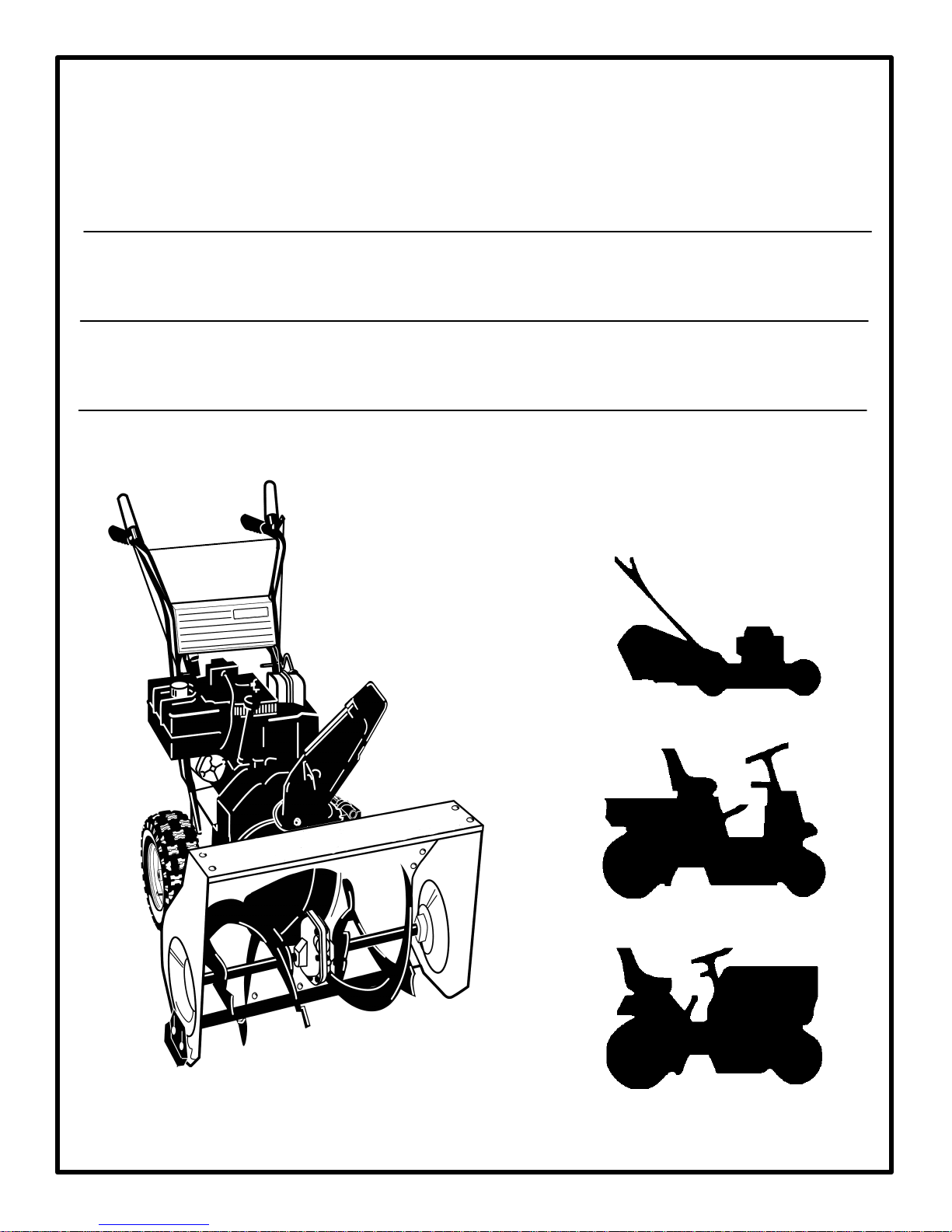
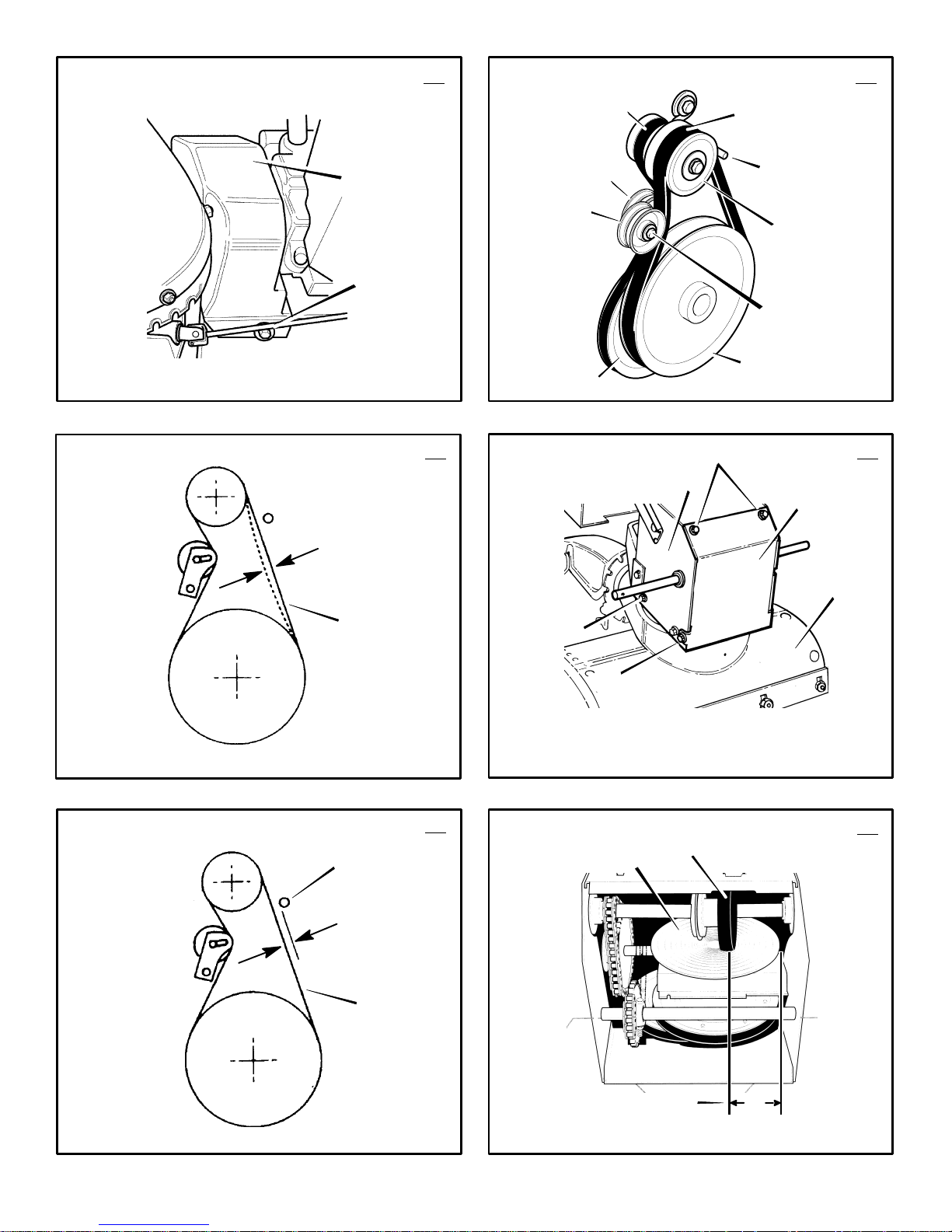
How To Remove The Snow Thrower
From The Carton
1.
(Figure 1)
shipping position.
2. Locate all parts that are packed separately
and remove from the carton.
3. Cut and discard the plastic ties that secure
the crank assembly to the pallet.
4. Remove and discard the packing material
from around the snow thrower.
5. Cut down all four corners of the carton and
lay the side panels flat.
6. Hold onto the lower handle and pull the snow
thrower off the carton.
CAUTION: DO NOT back over cables.
7. Remove the packing material from the handle assembly.
8. Cut the ties that secure the clutch control
cables (1) to the lower handle (2). Move the
cables away from the motor frame.
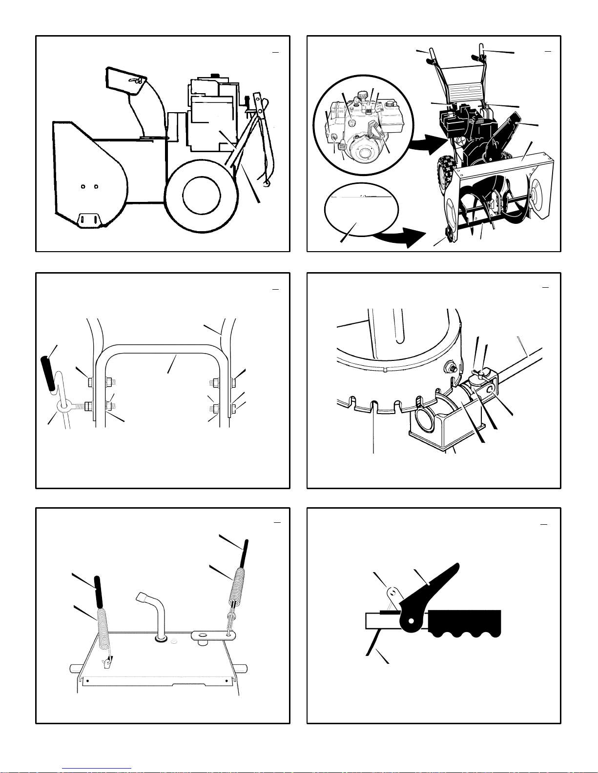
How To Assemble The Handle And
Crank Assembly
1.
(Figure 3)
fasteners (1) in the upper holes of the lower
handle.
2.
(Figure 2)
forward position.
3.
(Figure 3)
operating position.
NOTE: Make sure the cables are not
caught between the upper and lower handle.
4. Install the screw (4), flatwasher (5), lockwasher (6), and hex nut (7) into the bottom
hole on the right side of the handles. DO
NOT tighten until all fasteners are in place.
F–001043J
The snow thrower is shown in the
Loosen, but do not remove, the
Put the shift lever (6) into first
Raise the upper handle (2) to the
5. Locate the crank assembly (18) removed
earlier. Remove the locknut (9) and flat-
washer (10) from the eye bolt assembly
(11).
6. Install the eye bolt (11) through the lower
hole on the left side of the handles.
7. Install the flatwasher (10) and the locknut
(9) loosely on the eye bolt (11).
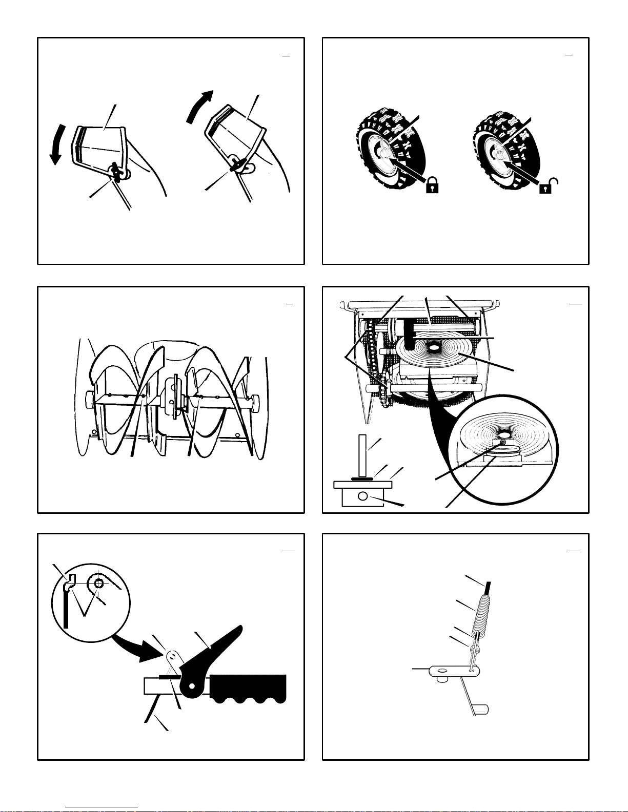
8.
(Figure 4)
clevis pin (13), universal joint pin (14), and
universal joint (16) from the crank rod assembly (15).
9. Mount the universal joint (16) into the end
of the worm gear (17). Make sure the large
holes are aligned.
10.Insert universal joint pin (14). Make sure
opening in universal joint pin (14) is aligned
with small opening in universal joint (16).
11.Mount the yoke end of crank rod (15)
around the universal joint (16). Fasten with
clevis pin (13) and cotter pin (12). Spread
ends of cotter pin (12) to lock in place.
12.
(Figure 3)
Make sure eye bolt (11) is properly aligned
and the crank (18) can freely rotate.
13.Tighten all handle fasteners.
Carefully remove cotter pin (12),
Tighten nut on eye bolt (11).
Check The Cables
1.
(Figure 5)
(1) and the auger drive cable (2). If the bot-
tom of the cables have become disconnected, reinstall the cable springs. Make sure
the long spring (3) is attached to the traction
drive and the short spring (4) is attached to
the auger drive.
2.
(Figure 6)
become disconnected from the drive levers
(6), attach the cables (5) to the “Z” fitting
(7).
How To Set The Skid Height
The snow thrower is equipped with height adjustable skids (7) mounted on the outside of the
auger housing (4). To adjust the height of the
skids, see “How To Adjust The Height Of The
Skids” in the Maintenance section.
Check the traction drive cable
If the top of the cables (5) have
(Figure 2)
How To Prepare The Engine
NOTE: The engine was shipped from the factory filled with oil. Check the level of oil. Add
oil as needed. Engine does not contain GASOLINE.
WARNING: Follow the engine
manufacturer’s instructions for the
type of fuel and oil to use. Always
use a safety fuel container. Do not smoke
when adding gasoline to the engine. When
inside an enclosure, do not fill with gasoline. Before you add fuel, stop the engine.
Let the engine cool for several minutes.
Check the oil. See the engine manufacturer’s
instructions for the type of fuel and oil to use.
Before you use the unit, read the information on
safety, operation, maintenance, and storage.
OPERATION
NOTE: Illustrations begin on page 3.
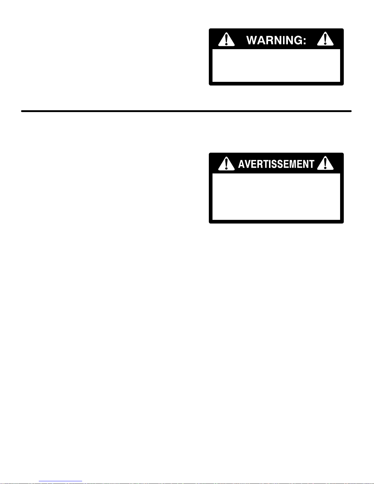
Know Your Snow Thrower
Read this Instruction Book and safety rules before operation the snow thrower. Compare the
11
(Figure 2)
ENGLISH
illustration with your snow thrower to familiarize
yourself with the location of various controls and
adjustments.
Traction Drive Lever (1) – Select the forward or
reverse direction of travel.
Crank Assembly (2) – Changes the direction of
the discharge chute.
Discharge Chute (3) – Changes the distance the
snow is thrown.
Auger Drive Lever (5) – Starts and stops the auger and impeller (snow gathering and throwing).
Speed Shift Lever (6) – Selects the speed of the
snow thrower.
Height Adjust Skid (7) – Adjusts the ground
clearance of the auger housing.
Ignition Key (8) – Must be inserted to start the engine.
Primer Button (9) – Injects fuel directly into the
carburetor for fast starts in cold weather.
Electric Start Button (10) – On electric start models, used to start the engine.
Switch Box (11) – On electric start models, used
to attach a 120 volt electric power cord.
Recoil Starter Handle (12) – Use to manually
start the engine.
Throttle Control (13) – Controls the speed of the
engine.
Choke Control (14) – Use to start a cold engine.
How To Control
The Discharge Of The Snow
WARNING: Never direct the discharge of snow toward bystanders.
WARNING: Always stop the engine
before unclogging the discharge
chute or the auger housing and be-
fore leaving the snow thrower.
1.
(Figure 2)
change the discharge direction of the snow.
2.
(Figure 7)
chute deflector (2).
3. Move the chute deflector (2) up for more
distance or down for less distance.
4. Tighten the wing knob (1).
How To Stop
The Snow Thrower
1. To stop discharging snow, release the auger
drive lever (5).
2. To stop the wheels, release the traction
drive lever (1).
3. To stop the engine, push the throttle control
lever (13) to off and remove the ignition key
(8).
How To Go Forward or Backward
(Figure 2)
1. To change the ground speed, first release the
traction drive lever (1) and then move the
speed shift lever (6) to the desired speed.
Turn the crank assembly (2) to
Loosen the wing knob (1) on the
(Figure 2)
Page 12
2. Ground speed is determined by snow conditions. Select the speed by moving the speed
shift lever (6) into the appropriate notch on
the shift lever plate.
Speed 1, 2 Wet, Heavy
Speed 3 Light
Speed 4 Very Light
Speed 5, 6 Transport only
3. To go forward, engage the traction drive
lever (1). Maintain a firm hold on the handle
as the snow thrower starts to move forward.
Guide the snow thrower by moving the handle either left or right. Do not attempt to push
the snow thrower.
4. To go backward, release the tractor drive
lever (1).
5. Move the speed shift lever (6) into either
first or second reverse.
6. Engage the traction drive lever (1).
IMPORTANT: Do not move the speed shift
lever (6) while the traction drive lever (1) is
engaged.
How To Throw Snow
1. Engage the auger drive lever (5).
2. To stop throwing snow, release the auger
drive lever (5).
WARNING: The operation of any
snow thrower can result in foreign
objects being thrown into the eyes,
which can result in severe eye damage.
Always wear safety glasses or eye shields
while operating the snow thrower. We recommend standard safety glasses or use a
wide vision safety mask over your glasses.
(Figure 2)
How To Use The Wheel Lockout Pin
(Figure 8)
1. The left hand wheel is secured to the axle
with a klick pin (1). This unit was shipped
with this klick pin (1) through the wheel hole
in the locked position (2).
2. For ease of maneuverability in light snow
conditions, change the klick pin (1) to an
unlocked position (3).
3. Disconnect the klick pin (1) from the wheel
locked position (2). Push the klick pin (1)
through the unlocked axle hole only. The unit
is now in the single wheel drive unlocked
position (3).
Before Starting The Engine
1. Before you service or start the engine, familiarize yourself with the snow thrower. Be
sure you understand the function and location of all controls.
2. Check the tension of the clutch cable before
starting the engine. See “How To Adjust The
Clutch Cable” in the Maintenance section of
this manual.
3. Make sure that all fasteners are tight.
4. Make sure the height adjust skids are properly adjusted. See “How To Adjust The Height
Of The Skids” in the Maintenance section of
this manual.
5. Check the air pressure in the tires. The correct air pressure is 14 PSI (1 BAR) to 17 PSI
(1.25 BAR). Do not exceed the maximum
amount of air pressure shown on the side of
the tire.
F–001043J
How To Stop The Engine
To stop the engine, move the throttle control
(3) to the stop position and remove the ignition
key (8). Keep the ignition key (8) in a safe
place. The engine will not start without the ignition key (8).
How To Start The Engine
Models equipped with an Electric Starter
NOTE: An electric starter kit can be added to
recoil start engines. Electric starter kits are
available from your nearest authorized service center.
WARNING: The starter is equipped
with a three–wire power cord and
plug and is designed to operate on
120 volt A.C. household current. The power
cord must be properly grounded at all tim es
to avoid the possibility of electrical shock
which can injure the operator. Carefully follow all instructions in the “How To Start The
Engine” section. Make sure that your house
wiring is a three–wire grounded system . If
you are not sure, ask a li censed el ectri cian.
If your house wire system is not a
three–wire grounded system, do not use
this electric starter under any conditions. If
your system is grounded but a three–hole
grounded receptacle is not available to start
the engine, have a three–hole grounded receptacle installed by a licensed electrician.
To connect a 120 volt A.C. power cord, always connect the power cord to the switch
box (11) on the engine first. Then, plug the
other end into the three–hole grounded re ceptacle. When disconnecting the power
cord, always unplug the end from the
three–hole grounded receptacle first.
How To Start A Cold Engine
1. Check the engine oil.
2. Fill the fuel tank with regular unleaded petrol.
See “How To Prepare The Engine”.
3. Make sure the traction drive lever (1) and
the auger drive lever (5) are in the disengaged (released) position.
4. Move the throttle control (13) to the fast
position.
5. Insert the ignition key (8) into the ignition
slot. Make sure the ignition key (8) snaps
into place. Do not turn the ignition key (8).
Remove the extra ignition key and keep in a
safe place.
6. Move the choke control (14) to the full
choke position.
7.
(Electric Start)
the switch box (11) located on the engine.
8.
(Electric Start)
power cord into a three–hole, grounded 120
VOLT, A.C. receptacle. (See the WARNING
in this section).
9. Push the primer button (9). Every time you
push the primer button (9), wait two seconds. For the number of times required to
push the primer button (9), see the engine
manufacturer’s instructions.
Connect the power cord to
Plug the other end of the
(Figure 2)
(Figure 2)
(Figure 2)
12
ENGLISH
10.
(Electric Start)
button (10) until the engine starts. Do not
crank for more than 10 seconds at a time.
The electric starter is thermally protected. If
the electric starter overheates, it will automatically stop and can only be restarted
when it has cooled to a safe temperature. A
wait of about 5 to 10 minutes is required to
allow the electric starter to cool.
11.
(Recoil Start)
handle (12). Do not allow the recoil starter
handle (12) to snap back. Slowly return the
recoil starter handle (12).
12.If the engine does not start in 5 or 6 tries,
See the “Trouble Shooting Chart” Instructions.
13.
(Electric Start)
lease the electric start button (10) and
move the choke control (14) to 1/2 choke
position. When the engine runs smoothly,
move the choke control (14) to the off position.
14.
(Electric Start)
cord from the three–hole receptacle. Then,
disconnect the power cord from the switch
box (11).
NOTE: In temperatures below 0F, allow
the engine to warm up for several minutes
before blowing snow.
15.When throwing snow, always run the engine
with the throttle control (13) in the fast position.
WARNING: Never run the engine
indoors or in enclosed, poorly ven-
tilated areas. Engine exhaust contains carbon monoxide, an odorless and
deadly gas. Keep hands, feet, hair and
loose clothing away from any moving parts
located on the engine or the snow thrower.
The temperature of muffler and nearby
areas may exceed 150°F. Avoid these
areas.
How To Start A Warm Engine
If an engine has been running and is still warm,
leave the choke control (14) in the off position
and do not push the primer button (9). If the
engine fails to start, follow the instructions “How
To Start A Cold Engine”.
NOTE: Do not use the primer button (9) to
start a warm engine.
How T o Start An Engine W ith A Frozen Electric
Starter
If the electric starter is frozen and will not turn
the engine, follow the instructions below.
1. Pull out the recoil starter handle (12) as far
2. Quickly release the recoil starter handle
If the engine still fails to start, repeat the two previous steps until the engine starts. Then, continue with the directions “How To Start A Cold
Engine”.
To help prevent the possible freeze–up of the
recoil starter and of the engine controls, proceed
as follows after each snow removal job.
1. With the engine running, quickly pull the re-
(Figure 2)
as possible.
(12). Allow the recoil starter handle (12) to
snap back against the recoil starter.
coil starter handle (12) three or four times
with a continuous full arm stroke. This will
produce a loud clattering sound that is not
harmful to the engine or starter.
Push on the electric start
Rapidly pull the recoil starter
When the engine starts, re-
First disconnect the power
(Figure 2)
Page 13

2. Stop the engine. Wipe all snow and moisture
from the carburetor cover, control levers and
cables. Also move the throttle control (13),
choke control (14), and recoil starter handle (12) several times.
How To Remove Snow or Debris From
The Auger Housing
WARNING: Do not attempt to remove snow or debris that may become lodged in auger housing
without taking the following precautions.
1. Release the auger drive lever (5).
2. Move the throttle control (13) to the stop
position.
3. Remove (do not turn) the ignition key (8).
4. Disconnect the spark plug wire.
(Figure 2)
5. Do not place your hands in the auger housing (4) or the discharge chute (3). Use a
pry bar to remove any snow or debris.
Snow Throwing Tips
1. For maximum snow thrower efficiency,
change the ground speed, NEVER change
the engine speed. The engine is designed to
deliver maximum performance at full throttle
and must be run in the fast position at all
times. In deep, freezing, or wet snow, reduce
forward speed. If the wheels slip, also reduce
forward speed.
2. Most efficient snow throwing is accomplished
when the snow is removed immediately after
if falls.
3. For complete snow removal, slightly overlap
each previous path.
4. Whenever possible, discharge the snow
down wind.
ENGLISH
5. For normal usage, set the skids so that the
scraper bar is 1/8” above the skids. For extremely hard–packed snow surfaces, adjust
the skids upward so that the scraper bar
touches the ground.
6. Rocks and gravel must not be picked up and
thrown by the machine. On gravel or crushed
rock surfaces, set the skids at 1–1/4 inch below the scraper bar. See “How To Adjust The
Height Of The Skids” in the Maintenance
section.
7. After each snow throwing job, allow the engine to idle for a few minutes. The snow and
accumulated ice will melt off the engine.
8. Clean the snow thrower after each use.
9. Remove ice, snow and debris from the entire
snow thrower. Flush with water to remove all
salt or other chemicals. Wipe snow thrower
dry.
F–001043J
13
Page 14
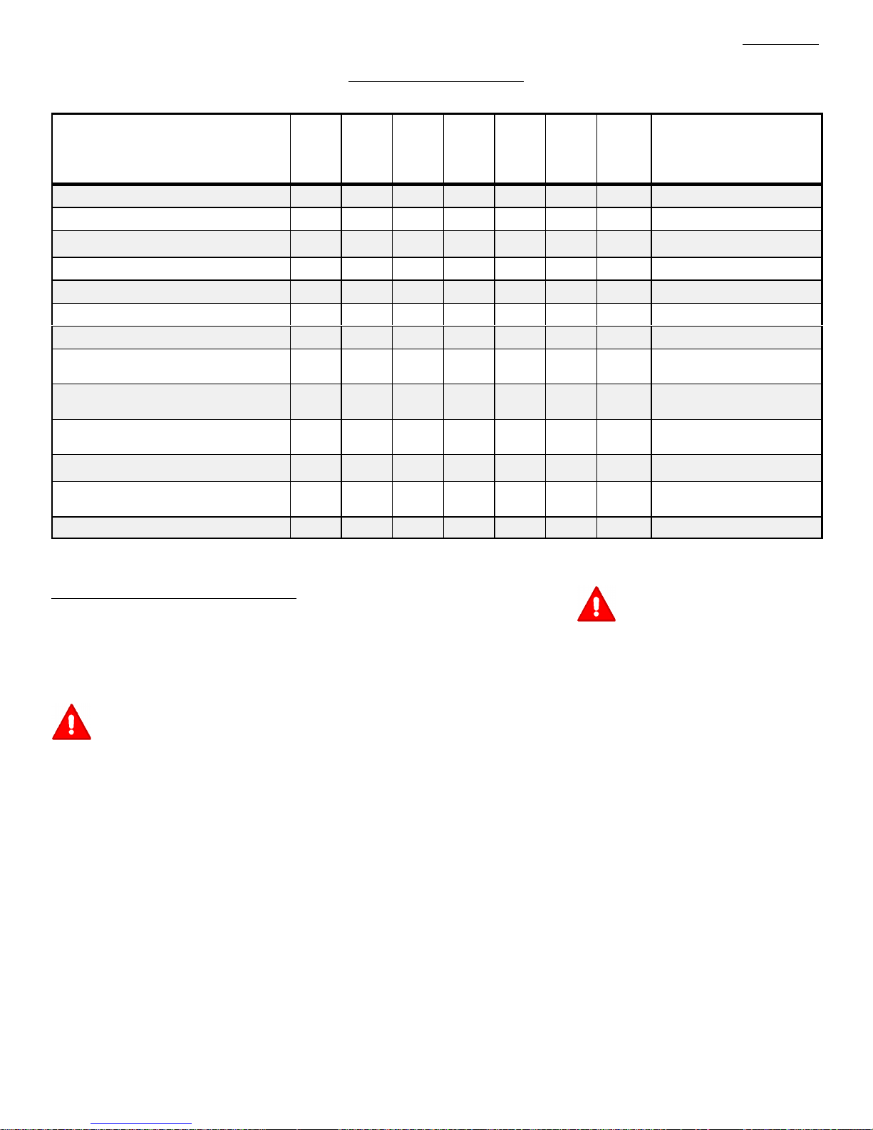
CUSTOMER RESPONSIBILITIES
SERVICE RECORDS
Fill in dates as you
complete regular
service.
Check Engine Oil Level
Change Engine Oil
Check And Tighten All Screws and Nuts
Check Spark Plug
Adjust Drive Belt
Check Fuel
Drain Fuel
Check Auger Clutch Cable Adjustment
(See Cable Adjustment)
Check Traction Clutch Cable Adjustment
(See Cable Adjustment)
Lubricate Disc Drive Plate Zerk
(See Maintenance)
Lubricate All Pivot Points
Lubricate Auger Shaft
(See Shear Bolt Replacement)
Lubricate Drive Chains and Sprockets
MAINTENANCE CHART
Before
Each
Use
First
2
Hours
Every
5
Hours
Every
10
Hours
Every
25
Hours
√ √ √
√ √
√ √ √
√
√ √
√ √
√
√ √
√ √
√ √
√ √
Each
Season
Before
Storage
√
√
√
ENGLISH
SERVICE DATES
MAINTENANCE
NOTE: Illustrations begin on page 3.
Use the following maintenance section to keep
your unit in good operating condition. All the
maintenance information for the engine is in the
engine manufacturer’s instructions. Before you
start the engine, read this book.
WARNING: Before you make an inspection, adjustment (except
carburettor), or repair, disconnect
the wire from the spark plug.
General Recommendations
The warranty on this snow thrower does not cover items that have been subjected to operator
abuse or negligence. To receive full value from
the warranty, the operator must maintain the
snow thrower as instructed in this manual.
Some adjustments must be made periodically to
properly maintain the snow thrower.
After Each Use
Check for any loose or damaged parts.
Tighten any loose fasteners.
Check and maintain the auger.
Check controls to make sure they are
functioning properly.
If any parts are worn or damaged, replace
immediately.
F–001043J
All adjustments in the Maintenance section of
this manual should be checked at least once
each season.
As Required
The following adjustment should be preformed
more than once each season.
1. Adjust the auger drive belt after the first 2 to
4 hours, again at mid–season, and twice
each season thereafter. See “How To Adjust
The Auger Drive Belt” in the Maintenance
section.
Lubrication
Every 10 Hours
1. Lubricate the Zerk fittings (1) every ten
hours with a grease gun.
2. Each time a shear bolt is replaced, the auger
shaft must also be greased.
3. Lubricate all pivot points.
Every 25 Hours
Lubricate the disc drive plate (1) every 25
hours, at the end of the season and before storage.
1.
(Figure 2)
first gear.
2. Remove the gas from the gas tank. Stand
the snow thrower up on the front end of the
auger housing (4).
(Figure 9)
(Figure 10)
Move the speed shift lever (6) to
14
WARNING: Drain the gasoline outdoors, away from fire or flame.
3.
(Figure 16)
side of the bottom panel (2).
4. Loosen the bolts (3) on each side of the bot-
tom panel (2).
5. Remove the bottom panel (2).
6.
(Figure 10)
clockwise by hand until the Zerk fitting (2) is
visible.
7. To prevent the rubber friction wheel (3) from
contacting the drive disc plate (1), put a
coin (4) (or a shim of equal thickness) between the rubber friction wheel (3) and the
disc drive plate (1).
8. Lubricate the Zerk fitting (2) with a grease
gun. Use a high temperature EP Moly
grease. Fill the Zerk fitting (2) only until
grease becomes visible below the bearing
assembly (5) located under the Zerk fitting
(2). DO NOT over fill. Clean all excess
grease from the friction disc hub.
CAUTION: Do not allow grease to come
in contract with the disc drive plate (1) or
the friction wheel (3) or damage will result.
9. Remove coin (4) used in step 7. Make sure
that a gap exists between the friction wheel
(3) and the disc drive plate (1).
10.
(Figure 16)
11.Tighten the bolts (3) on each side of the bot-
tom panel (2).
12. Install the bolts (1) on each side of the bottom panel (2).
Remove the bolts (1) on each
Turn the disc drive plate (1)
Install the bottom panel (2).
Page 15

Items Not To Lubricate
1. Do not lubricate the hex shaft and sprockets (6). All bearings and bushings are life-
time lubricated. For storage, put a slight
amount of 5W–30 motor oil on a cloth and
wipe the hex shaft and sprockets (6) to
prevent rust.
2. If grease or oil comes in contact with the
disc drive plate (1) or the friction wheel
(3), the friction wheel (3) can be damaged.
Make sure to thoroughly clean the disc drive
plate (1) and the friction wheel (3).
CAUTION: Any greasing or oiling of the
above components can cause contamination of the friction wheel (3). If the disc
drive plate (1) or the friction wheel (3) become contaminated with grease or oil,
damage to the friction wheel will result.
3. The auger gear case is lubricated at the factory and does not require additional lubrication. If for some reason the lubricant leaks
out, have the auger gear case checked by a
factory authorized service center.
(Figure 10)
How To Adjust The Height Of The Skids
(Figure 2)
This snow thrower is equipped with two height
adjustable skids (7). These skids elevate the
front of the snow thrower. For normal hard surfaces, such as a paved driveway or walk, adjust
the skids as follows.
1. Put the snow thrower on a level surface.
2. Make sure both tires are equally inflated.
The correct air pressure is 14 PSI (1 BAR) to
17 PSI (1.25 BAR). Do not exceed the maximum amount of air pressure shown on the
side of the tire.
3. Put the extra shear bolts (found in the parts
bag) under each end of the scraper bar (15)
next to the adjustable skids (7).
4. Loosen the mounting nuts (16) that hold the
adjustable skids (7). To bring the front of the
snow thrower down, raise each adjustable
skids (7) . Tighten the mounting nuts (16).
NOTE: For rocky or uneven surfaces, raise
the front of the snow thrower by moving the
adjustable skids (7) down.
WARNING: Be certain to maintain
proper ground clearance for the
area to be cleared. Objects such
as gravel, rocks or other debris, if struck
by the impeller, can be thrown with sufficient force to cause personal injury, property damage or damage to the snow thrower.
How To Adjust
The Scraper Bar
After considerable use, the scraper bar (15) will
become worn. The scraper bar (15), in conjunction with the skids, must be adjusted to allow
1/8 inch clearance between the scraper bar
(15) and the sidewalk or area to be cleared.
1. Put the snow thrower on a level surface.
2. Make sure both tires are equally inflated.
The correct air pressure is 14 PSI (1 BAR) to
17 PSI (1.25 BAR). Do not exceed the maximum amount of air pressure shown on the
side of the tire.
3. Loosen the carriage bolts and nuts that hold
the scraper bar (15) to the auger housing
(4).
F–001043J
(Figure 2)
4. Adjust the scraper bar (15) to allow 1/8 inch
clearance between the scraper bar (15) and
the sidewalk or area to be cleared.
5. Tighten the carriage bolts and nuts. Make
sure that the scraper bar (15) is parallel with
the sidewalk or area to be cleared.
6. To extended the life of the scraper bar (15),
remove and reverse the mounting of the
scraper bar (15).
How To Check And Adjust The Cables
The traction drive cable and the auger drive
cable are adjusted at the factory. During normal
use, a cable can become stretched and must be
checked and adjusted as follows.
How To Check The Cables
1. To check for correct adjustment, disconnect
the “Z” fitting (1) from the drive lever (2).
2. Move the drive lever (2) forward until the
drive lever (2) is contacting the plastic
bumper (3).
3. The control cable is correctly adjusted if the
center of the “Z” fitting (1) is aligned (4)
with the hole in the drive lever (2) and there
in no droop in the cable.
How To Adjust The Cables
1. Remove the gas from the gas tank. Stand
the snow thrower up on the front end of the
auger housing.
WARNING: Drain the gasoline outdoors, away from fire or flame.
2.
(Figure 11)
from the drive lever (2).
3.
(Figure 12)
pose the spring (5). Push the cable (6)
through the spring (5) to expose the square
end (7) on the cable (6).
4. Hold the square end (7) with pliers and adjust the locknut (8) in or out until the excess
slack is removed.
5. Pull the cable (6) back through the spring
(5).
6.
(Figure 11)
drive lever (2).
NOTE: When the traction drive belt or the
auger drive belt is adjusted or replaced,
check and adjust the cable.
Disconnect the “Z” fitting (1)
Pull the spring cover up to ex-
Connect the “Z” fitting (1) to the
(Figure 11)
How To Adjust The Belts
The belts will stretch during normal use. If you
need to adjust the belts due to wear or stretch,
proceed as follows.
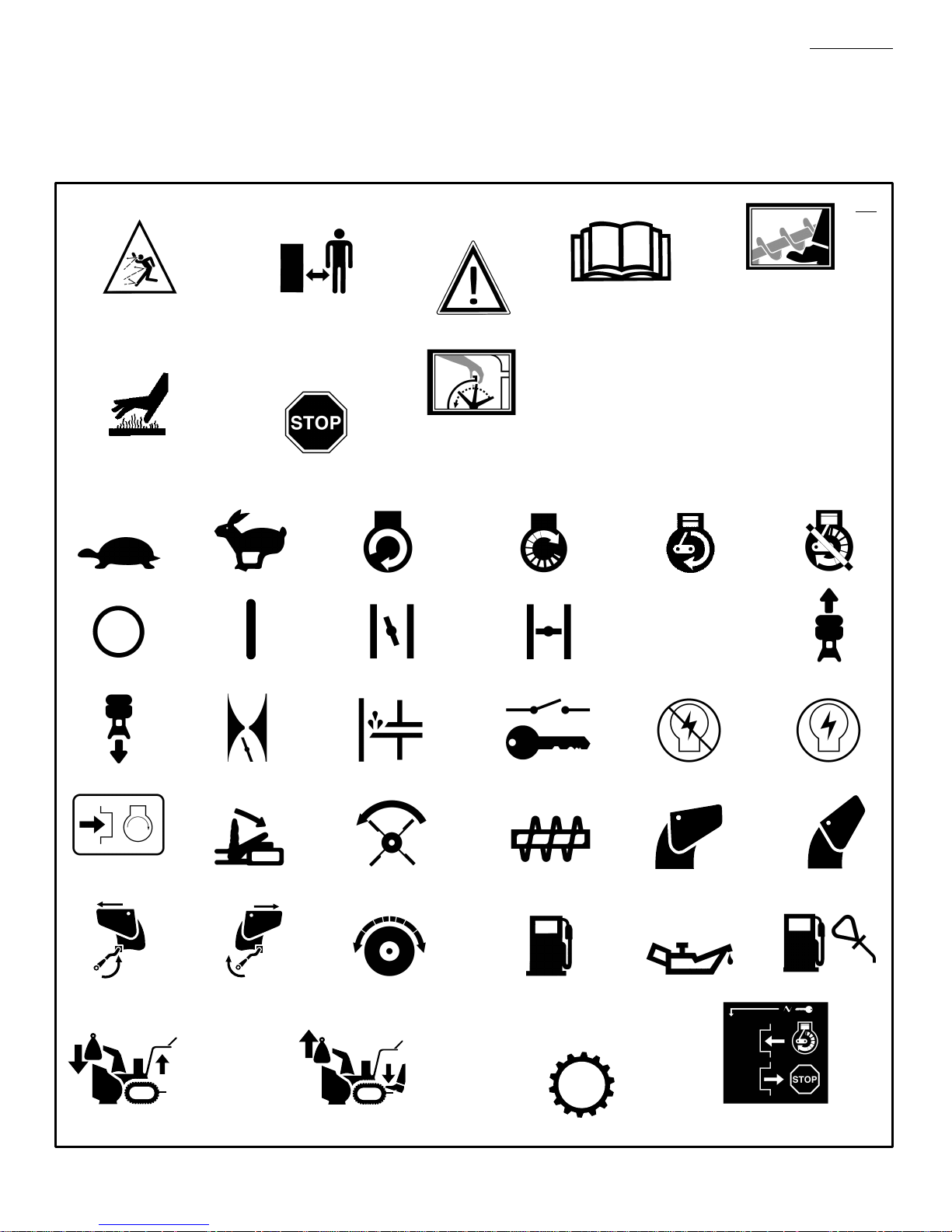
How To Adjust The Auger Drive Belt
If the snow thrower will not discharge snow,
check the adjustment of the auger drive cable.
See “How To Check And Adjust The Cables” in
the Maintenance section. If the adjustment is
correct, then check the condition of the auger
drive belt. If the auger drive belt is damaged,
replace the auger drive belt. See “How To Replace The Belts” in the Maintenance section. If
the auger drive belt is loose, adjust as follows.
1. Disconnect the spark plug wire.
2.
(Figure 13)
cover (1). Remove the belt cover (1).
Remove screw (2) from belt
15
ENGLISH
3.
(Figure 14)
pulley (3) Move the idler pulley (3) 1/8 inch
toward the auger drive belt (4).
4. Tighten the nut (2).
5.
(Figure 15)
Check the tension on the auger drive belt
(4). In correct adjustment, the auger drive
belt (4) will deflect 1/2 inch (5) with moder-
ate pressure. If the adjustment is not correct,
repeat the adjustment.
6.
(Figure 13)
screw (2).
7. Check the adjustment of the auger drive
cable. See “How To Check And Adjust The
Cables” in the Maintenance section.
8. Attach the spark plug wire.
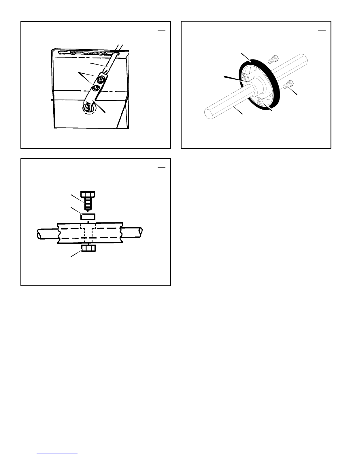
Traction Drive Belt
The traction drive belt has constant spring pressure and does not require an adjustment. If the
traction drive belt is slipping, replace the belt.
See “How To Replace The Belts” in the Maintenance section.
How To Replace The Belts
The drive belts are of special construction and
must be replaced with original factory replacement belts available from your nearest authorized service center.
Some steps require the assistance of a second
person.
How To Remove the Auger Drive Belt
If the auger drive belt is damaged, the snow
thrower will not discharge snow. Replace the
damaged belt as follows.
1.
(Figure 2)
tank. Stand the snow thrower up on the front
end of the auger housing (4).
2. Disconnect the spark plug wire.
3.
(Figure 13)
cover (1). Remove the belt cover (1).
4.
(Figure 16)
side of the motor mount frame (6).
5. Loosen the bolts (3) on each side of the mo-
tor mount frame (6). The auger housing
(8) and the motor mount frame (6) will sep-
arate, hinged by bolts (3).
6.
(Figure 14)
the belt guide (9) away from the auger
drive pulley (10).
7. Loosen the nut (2) on the idler pulley (3).
Pull the idler pulley (3) away from the auger
drive belt (4).
8. Remove the old auger drive belt (4) from
the auger drive pulley (10) and from pulley
(11). Replace the auger drive belt (4) with
an original factory replacement belt available
from an authorized service center.
9. Install the new auger drive belt (4) onto the
auger drive pulley (10) and onto pulley
(11).
10.Adjust the auger drive belt (4). See “How To
Adjust The Auger Drive Belt” in the Maintenance section.
11.Adjust the belt guide (9). See “How To Adjust The Belt Guide” in the Maintenance section.
Loosen the nut (2) on the idler
Depress the auger drive lever.
Install the belt cover (1). Tighten
Remove the gas from the gas
WARNING: Drain the gasoline outdoors, away from fire or flame.
Remove screw (2) from belt
Remove the bolts (5) on each
Loosen the belt guide (9). Pull
Page 16

12.
(Figure 16)
of the motor mount frame (6).
13.Tighten the bolts (3) on each side of the mo-
tor mount frame (6).
14.
(Figure 13)
screw (2).
15.Check the adjustment of the cables. See
“How To Check And Adjust The Cables” in
the Maintenance section.
16.Connect the spark plug wire.
How To Remove the Traction Drive Belt
If the snow thrower will not move forward, check
the traction drive belt for wear or damage. If the
traction drive belt is worn or damaged, replace
the belt as follows.
1.
(Figure 2)
tank. Stand the snow thrower up on the front
end of the auger housing (4).
2. Disconnect the spark plug wire.
3. Remove the auger drive belt. See “How To
Remove The Auger Drive Belt” in the Maintenance section.
4.
(Figure 14)
pulley (12) away from the traction drive
belt (13).
5. Remove the old traction drive belt (13) from
the traction drive pulley (14) and from the
engine pulley (15). Replace the traction
drive belt (13) with an original factory re-
placement belt available from an authorized
service center.
6. Install the new traction drive belt (13) onto
the traction drive pulley (14) and onto en-
gine pulley (15).
7. Make sure the traction drive idler pulley
(12) is properly aligned with the traction
drive belt (13).
8. Install and adjust the auger drive belt (4).
See “How To Remove The Auger Drive Belt”
in the Maintenance section.
9. Adjust the belt guide (9). See “How To Adjust The Belt Guide” in the Maintenance section.
10.
(Figure 16)
of the motor mount frame (6).
11.Tighten the bolts (3) on each side of the mo-
tor mount frame (6).
12.
(Figure 13)
screw (2).
13.Check the adjustment of the cables. See
“How To Check And Adjust The Cables” in
the Maintenance section.
14.Connect the spark plug wire.
Install the bolts (5) on each side
Install the belt cover (1). Tighten
Remove the gas from the gas
WARNING: Drain the gasoline outdoors, away from fire or flame.
Pull the traction drive idler
Install the bolts (5) on each side
Install the belt cover (1). Tighten
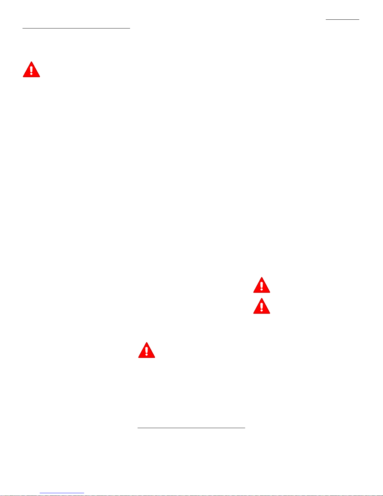
How To Adjust The Belt Guide
1. Disconnect spark plug wire.
2.
(Figure 13)
belt cover (1).
3.
(Figure 2)
4.
(Figure 17)
the belt guide (2) and auger drive belt (3).
The correct distance (4) is 1/8 inch (3.175
mm).
5. If an adjustment is necessary, loosen the
mounting bolt for the belt guide (2). Move
the belt guide (2) to the correct position
(4). Tighten the mounting bolt for the belt
guide (2).
F–001043J
Remove screw (2). Remove the
Engage the auger drive lever (5).
Measure the distance between
6.
(Figure 13)
screw (2).
7. Connect the spark plug wire.
Install the belt cover (1). Tighten
How To Adjust Or Replace The Friction
Wheel
How To Check The Friction Wheel
If the snow thrower will not move forward, check
the traction drive belt, the traction drive cable or
the friction wheel. If the friction wheel is worn or
damaged, it must be replaced. See “How To
Replace the Friction Wheel” in this section. If the
friction wheel is not worn or damaged, check as
follows.
1.
(Figure 2)
tank. Stand the snow thrower up on the front
end of the auger housing (4).
2. Disconnect the spark plug wire.
3.
(Figure 16)
side of the bottom panel (2).
4. Loosen the bolts (3) on each side of the bot-
tom panel (2).
5. Remove the bottom panel (2).
6.
(Figure 2)
in the first forward gear.
7.
(Figure 18)
wheel (4) on the disc drive plate (5). In the
correct position (7), the right outer side of
the disc drive plate (5) must be three inches
(7.62cm.) from the center of the friction
wheel (4). If the friction wheel (4) is not in
the correct position (7), adjust as follows.
How To Adjust The Friction Wheel
1.
(Figure 19)
speed control rod (8).
2.
(Figure 18)
the correct position (7).
3.
(Figure 19)
speed control rod (8).
4.
(Figure 16)
5. Tighten the bolts (3) on each side of the bot-
tom panel (2).
6. Install the bolts (1) on each side of the bottom panel (2).
How To Replace The Friction Wheel
If the friction wheel is worn or damaged, the
snow thrower will not move forward. The friction
wheel must be replaced as follows.
1.
(Figure 2)
tank. Stand the snow thrower up on the front
end of the auger housing (4).
2. Disconnect the spark plug wire.
3.
(Figure 16)
side of the bottom panel (2).
4. Loosen the bolts (3) on each side of the bot-
tom panel (2).
5. Remove the bottom panel (2).
6.
(Figure 19)
(8) from the spring lever (9).
Remove the gas from the gas
WARNING: Drain the gasoline outdoors, away from fire or flame.
Remove the bolts (1) on each
Position the shift speed lever (6)
Note the position of the friction
Loosen the bolts (1) on the
Move the friction wheel (4) to
Tighten the bolts (1) on the
Install the bottom panel (2).
Remove the gas from the gas
WARNING: Drain the gasoline outdoors, away from fire or flame.
Remove the bolts (1) on each
Remove the speed control rod
16
ENGLISH
7.
(Figure 20)
that hold the friction wheel (5) to the hub
(6).
8.
(Figure 10)
the bearing plates (7) on each side of the
hex shaft (8).
NOTE: Take special note of the position of
the washers and retaining ring on the hex
shaft (8) and the sprocket assembly.
9. Remove the bearing plate (7) from the right
side. Do not remove the hex shaft (8). Leave
the hex shaft (8) in position. Carefully raise
hex shaft (8) just enough to allow the fric-
tion wheel (3) to be removed.
10.
(Figure 20)
from the hub (6). Slip the friction wheel (5)
toward the right off the hex shaft (8).
11.Assemble the new friction wheel (5) onto
hub (6) with the fasteners removed earlier.
12.
(Figure 10)
the right side. Make sure the hex shaft (8) is
engaged with both bearing plates (7) and
that the washers and retaining ring are
installed in the original position.
13.Fasten the bearing plates (7) using the four
bolts removed earlier.
14.Make sure the hex shaft (8) turns freely.
15.
(Figure 19)
(8) to the spring lever (9).
16.Check the adjustment of the friction wheel.
See “How To Adjust The Friction Wheel” in
this section.
17.Make sure the friction wheel and the disc
drive plate are free from grease or oil.
18.
(Figure 16)
19.Tighten the bolts (3) on each side of the bot-
tom panel (2).
20. Install the bolts (1) on each side of the bottom panel (2).
21.Connect the spark plug wire.
How To Replace the Auger Shear Bolt
The augers are secured to the auger shaft with
special shear bolts. These shear bolts are designed to break and protect the machine if an
object becomes lodged in the auger housing.
Do not use a harder bolt as the protection provided by the shear bolt will be lost.
To replace a broken shear bolt, proceed as follows. Extra shear bolts were provided in the assembly parts bag.
1.
(Figure 2)
the stop position. Disengage all controls.
2. Disconnect the spark plug wire. Make sure
all moving parts have stopped.
3.
(Figure 9)
fitting (1) with a grease gun.
4.
(Figure 21)
the hole in the auger shaft. Install the new
shear bolt (2), spacer (3) and locknut (4).
5. Connect the spark plug wire.
How To Prepare The Snow Thrower For
Storage
fumes can cause an explosion or a fire.
1. Drain the fuel tank.
Remove the three fasteners (4)
Remove the four bolts that hold
Remove the friction wheel (5)
Install the bearing plate (7) onto
Attach the speed control rod
Install the bottom panel (2).
WARNING: For safety and to protect the machine, use only original
equipment shear bolts.
Move the throttle control (13) to
Lubricate the auger shaft Zerk
Align the hole in the auger with
WARNING: Do not remove gasoline
while inside a building, near a fire,
or while you smoke. Gasoline
Page 17

2. Let the engine run until it is out of gasoline.
3. Drain the oil from the warm engine. Fill the
engine crankcase with new oil.
4. Remove the spark plug from the cylinder.
Pour one ounce of oil into the cylinder. Slowly pull the recoil–start grip so that the oil will
protect the cylinder. Install a new spark plug
in the cylinder.
5. Thoroughly clean the snow thrower.
6. Lubricate all lubrication points. See the Maintenance section.
7. Be sure that all nuts, bolts and screws are
securely fastened. Inspect all visible moving
parts for damage, breakage and wear. Replace if necessary.
8. Cover the bare metal parts of the blower
housing, auger, and the impeller with spray
rust preventative lubricant.
9. Put the unit in a building that has good ventilation.
10.If the machine must be stored outdoors,
block up the snow thrower to be sure the entire machine is off the ground.
11.Cover the snow thrower with a suitable protective cover that does not retain moisture.
Do not use plastic.
How To Order Replacement Parts
The replacement parts are shown either on the
back pages of this Instruction Book or in a
separate Parts List Book.
Use only manufacturer’s authorized or approved
replacement parts. The letter placed on the end
of the part number denotes the type of finish for
the part, C for chrome, Z for zinc, a PA for
purchased assembly. It is important that you
include this when ordering a part. Do not use
attachments or accessories not specifically
recommended for this unit. In order to obtain
proper replacement parts you must supply the
model number (see nameplate).
Replacement parts, except for the engine,
transmission, transaxle or differential, are
available from the store where the product was
purchased, a service shop recommended by the
store or from a “Murray, Inc. Central Parts
ENGLISH
Distributor” listed on the back page of this
Instruction Book.
If you are unable to obtain parts or service in the
manner outlined above, then contact:
MURRAY, INC.
Outdoor Power Equipment
Customer Service Department
P.O. Box 268
Brentwood, Tennessee 37027
1–800–251–8007 Collect telephone calls will not
be accepted.
Replacement parts for the engine, transaxle, or
transmission, are available from the
manufacturer’s authorized service center found
in the yellow pages of the telephone directory.
Also, see the individual engine or transmission
warranties to order replacement parts.
When ordering the following information is
required:
(1) The Model Number
(2) Serial Number
(3) Part Number
(4) Quantity
TROUBLE SHOOTING CHART
TROUBLE CAUSE CORRECTION
Difficult starting Defective spark plug. Replace spark plug.
Water or dirt in fuel system. Use carburetor bowl drain to flush and refill with
Engine runs erratic Blocked fuel line, empty gas tank, or stale
Engine stalls Unit running on CHOKE. Set choke lever to RUN position.
Engine runs erratic;
Loss of power
Excessive vibration Loose parts: damaged impeller Stop engine immediately and disconnect spark
Unit fails to propel itself Drive belt loose or damaged. Replace drive belt.
Unit fails to discharge snow Auger drive belt loose or damaged. Adjust auger drive belt; replace if damaged.
gasoline
Water or dirt in fuel system. Use carburetor bowl drain to flush and refill with
Incorrect adjustment of traction drive cable Adjust traction drive cable.
Worn or damaged friction wheel. Replace friction wheel.
Auger control cable not adjusted correctly. Adjust auger control cable.
fresh fuel.
Clean fuel line; check fuel supply; add fresh
gasoline
fresh fuel.
plug wire. Tighten all bolts and make all
necessary repairs. If vibration continues, have
the unit serviced by a competent repairman.
F–001043J
Shear bolt broken Replace shear bolt
Discharge chute clogged. Stop engine immediately and disconnect spark
plug wire. Clean discharge chute and inside of
auger housing.
Foreign object lodged in auger Stop engine immediately and disconnect spark
plug wire. Remove object from auger.
17
Page 18

SOMMAIRE
INFORMATIONS SUR LE PRODUIT 18
INFORMATIONS DESTINEES AU
PROPRIETAIRE 18
PICTOGRAMMES INTERNATIONAUX 19
MONTAGE 21
FONCTIONNEMENT 21
MAINTENANCE 24
TABLEAU DE MAINTENANCE 24
TABLEAU DE DEPANNAGE 28
GARANTIE LIMITEE DE DEUX ANS
Murray, Inc. garantie auprès de l’acheteur initial
que cette machine est dépourvue de défauts
matériels et de construction sous utilisation et
entretien normaux pendant une durée de deux
(2) ans à partir de la date d’acquisition ; cette
garantie cependant ne couvre pas les moteurs,
accessoires (tels que moteurs électriques) et
pièces d’usure normale (exceptées les pièces
mentionnées ci–dessous) étant donné que les
sociétés fabriquant ces articles offrent leurs
propres garanties et fournissent des réparations
par le biais de leurs centres de maintenance
spécialisés agréés. Pour plus d’informations, se
reporter aux garanties couvrant ces pièces
particulières. Si vous ne savez pas si votre
machine contient ou est équipée d’une ou
plusieurs de ces pièces, adressez vous à votre
revendeur avant l’acquisition. Sous réserve des
modalités et conditions de cette garantie limitée,
nous nous engageons à réparer ou remplacer, à
notre discrétion et gratuitement auprès de
l’acheteur initial, toute pièce couverte par cette
garantie limitée jusqu’à l’expiration de la garantie
applicable.
Les pièces d’usure normale comprennent les
courroies d’entraînement, les fraises
hélicoïdales, les goupilles de cisaillement, les
pneumatiques, et les phares. Ces pièces sont
garanties sans défaut matériel ou de
construction dans l’état où elles ont été livrées
avec le produit. Toute réclamation concernant la
réparation ou le remplacement d’une pièce
d’usure normale doit être effectuée dans les
trente (30) jours suivant la date d’acquisition.
Aucune réclamation ne sera honorée
concernant des dommages provenant de la
simple utilisation, d’un usage abusif, ou d’une
mauvaise utilisation.
Cette garantie Murray, Inc. de deux (2) ans
constitue votre recours exclusif ; cependant,
cette garantie est nulle ou ne s’applique pas aux
machines ayant été modifiées, endommagées,
fait l’objet d’une utilisation abusive, ou utilisées
lors d’une location ou à des fins commerciales
et/ ou professionnelles (autre que domestiques).
Votre garantie ne couvre pas les réglages
mécaniques mineurs non dus à des défauts
matériels de fabrication. Consultez votre manuel
d’utilisation pour obtenir une assistance
concernant ces réglages.
Pour effectuer une réclamation sous la garantie
limitée de deux (2) ans Murray, Inc., retourner
FRANÇAIS
la machine, (ou, suivant notre autorisation
préalable, la pièce défectueuse) accompagnée
de votre preuve d’achat, auprès du Centre de
maintenance agréé le plus proche de chez vous.
Pour localiser le centre de maintenance le plus
proche, contactez le Distributeur de pièces
régional de votre région figurant sur la liste
fournie avec votre machine, ou consultez les
pages jaunes de votre annuaire téléphonique
local. Si vous nous retournez la machine
complète, nous réparerons celle–ci. Si nous
autorisons seulement le retour de la pièce
défectueuse, nous effectuerons soit la réparation
de celle–ci, soit son remplacement. Cette
garantie limitée Murray, Inc. de deux (2) ans
vous octroie des droits légaux spécifiques, et
vous pouvez également vous prévaloir d’autres
droits dont le contenu varie selon l’Etat où ils
s’appliquent. Cette garantie limitée est
délivrée en lieu et place de toute garantie
stipulée ou tacite, ceci incluant la garantie
tacite de commerciabilité et la garantie de
fonctionnalité pour une tâche définie. Si
vous souhaitez recevoir des informations
supplémentaires concernant cette garantie
écrite ou une assistance quant à l’obtention de
services de réparation, adressez–vous à :
MURRAY, INC.
Outdoor Power Equipment
Customer Service Department
P.O. Box 268
Brentwood, Tennessee 37027
1–800–251–8007
INFORMATIONS SUR LE
PRODUIT
Le propriétaire doit être certain que tous les
renseignements sur le produit sont inclus avec
la tondeuse. Ces renseignements comprennent
les MANUELS D’INSTRUCTION, les PIECES
DE RECHANGE, et les GARANTIES. Ces
renseignements doivent être inclus pour
s’assurer que les lois d’Etat et les autres lois
sont observés.
INFORMATIONS DESTINEES AU
PROPRIETAIRE
Ce manuel se dirige aux personnes familiarisées
avec ce genre de manipulations mécaniques. La
plupart des ouvrages de maintenance ne mentionnent pas toutes les étapes, et cet ouvrage ne
fait pas exception. Serrer ou desserrer des attaches sont des manipulations que tout le monde
peut effectuer avec une certaine pratique. Lisez
et suivez ces instructions avant d’utiliser la tondeuse.
Apprenez à maîtriser l’appareil : si vous comprenez le fonctionnement de ce modèle, vous en
obtiendrez les meilleures performances. Au fur
et à mesure que vous lisez le manuel, reportez–
vous aux illustrations. Sachez repérer l’emplacement des commandes et leur fonction. Afin de
prévenir tout risque d’accident, observez les instructions de fonctionnement et les règles de sé-
F–001043J
curité. Conservez ce manuel pour future
référence.
IMPORTANT : De nombreux appareils ne sont
pas assemblés et sont vendus démontés dans
leur carton d’emballage. Il est alors de la responsabilité du propriétaire de veiller à ce que les
instructions de montage présentes dans le manuel soient suivies en toute exactitude. D’autres
appareils sont vendus entièrement montés. En
ce qui concerne les machines déjà montées, il
est de la responsabilité du propriétaire de veiller
à ce que la machine soit correctement assemblée. Le propriétaire doit vérifier attentivement la
machine en fonction des instructions présentes
dans le manuel avant de commencer à utiliser
celle–ci.
DANGER : repérez ce symbole qui vous
indiquera les précautions de sécurité importantes. Ce symbole signifie : “Attention!
Soyez prudent! Vous encourrez des risques.”
Responsabilité de l’utilisateur
La responsabilité de l’utilisateur est de
suivre les instructions ci–dessous.
1. Lire soigneusement ce manuel et suivre les
règles indiquées pour un usage de la tondeuse en toute sécurité.
18
2. Suivre les instructions de montage et de
préparation.
3. Inspecter la tondeuse.
4. S’assurer que l’utilisateur de la tondeuse
sait bien utiliser les équipements standards
et les accessoires.
5. N’utiliser la tondeuse qu’avec les équipements de protection, les écrans et autres
dispositifs de sécurité bien en place et en
bon état de marche.
6. Procéder aux réglages nécessaires.
7. Entretenir la tondeuse avec les pièces de
rechange autorisées ou agréées.
8. Veiller à ce qu’un entretien complet soit effectué sur la tondeuse.
Prise de conscience environnementale
Ne pas remplir le réservoir d’essence du
moteur au ras–bord.
Vider l’essence pendant le remisage hors
saison.
N’utiliser que de l’essence sans plomb.
Entretenir régulièrement le filtre à air.
Changer l’huile régulièrement. Utiliser de
l’huile de grade 5W–30.
Effectuer un réglage du moteur régulière-
ment.
Conserver le matériel en bon état de mar-
che.
Eliminer l’huile de vidange de façon écolo-
gique.
Page 19

PICTOGRAMMES INTERNATIONAUX
IMPORTANT : les pictogrammes suivants
sont situés sur votre appareil ou dans la documentation ci–jointe. Avant de vous servir
de la tondeuse, apprenez à reconnaître chaque pictogramme.
FRANÇAIS
Symboles de signalisation de danger
DANGER
Projection d’objets.
Eloigner tout spectateur.
DANGER
surface brûlante
DANGER
Projection d’objets.
Eloigner tout spectateur.
STOP
DANGER
Arrêter le moteur avant de
DANGER
déboucher le déversoir!
IMPORTANT
Lire le manuel de l’utilisa-
teur avant de faire fonc-
tionner cette machine
Symboles de commandes et de conduite
Lent Rapide Démarrage électrique Démarrage moteur Moteur en marche
24
Prévenir les blessures dues
rotation. Ecarter vos mains,
DANGER
à la fraise hélicoïdale en
pieds, et vêtements.
Moteur à l’arrêt
Arrêt moteur Marche Arrêt starter Marche starter
Marche arrière
Appuyer pour en-
gager le starter
électrique
Décharge gauche Décharge droite
KGS
Accélérateur Bouton d’amorçage Clé du démarreur
Embrayage
Embrayage de la fraise Collecteur de la fraise
Embrayage des roues
KGS
Carburant huile
N
Point mort
Démarreur
hors tension
Déversoir ABAISSE Déversoir LEVE
Marche avant
Démarreur
sous tension
Mélange essence/huile
Transfert de poids
Lever la manette pour embrayer
F–001043J
Abaisser la manette pour débrayer
Transfert de poids
19
Transmission
Clé du démarreur
Insérer pour mettre en marche,
retirer pour arrêter.
Page 20

REGLES DE SECURITE A SUIVRE POUR L’UTILISATION DES CHASSE–NEIGE
SELON LES RECOMMANDATIONS DE L’AMERICAN NATIONAL STANDARDS INSTITUTE
IMPORTANT : les normes de sécurité requiè-
rent des contrôles de la présence du conducteur
pour limiter les risques de blessures. Votre chasse–neige est équipé de ces contrôles. Ne pas
tenter de rendre la fonction de contrôle de la
présence du conducteur inopérante quelles que
soient les circonstances.
Conseils préliminaires
1. Lisez soigneusement le manuel de fonctionnement et les consignes. Familiarisez–vous
avec les commandes ainsi qu’avec les modes appropriés d’utilisation de la machine.
2. N’autorisez jamais un enfant ou une personne ignorant ces consignes de sécurité à se
servir de la tondeuse.
3. Assurez–vous que toute personne, les enfants en particulier, sont à l’écart du lieu
d’utilisation de la tondeuse.
4. User de précautions pour éviter de glisser ou
de tomber, surtout lors de la conduite en marche arrière.
Préparation
1. Inspectez à fond le lieu où le matériel doit
être utilisé. Enlevez tous paillassons, patins,
planches, fils, et autres corps étrangers.
2. Débrayer toutes les comm andes av ant de
démarrer le moteur.
3. Ne pas faire fonctionner la machine sans porter de vêtements d’extérieur appropriés pour
l’hiver. Chausser des chaussures permettant
d’améliorer l’adhérence sur surfaces glis san tes.
4. Manipuler le carburant avec prudence ; celui–
ci est hautement inflammable.
a. Utiliser un bidon d’essence approprié.
b. Ne jamais retirer le bouchon du réservoir
d’essence ou ajouter de l’essence dans
un moteur en marche ou un moteur
chaud.
c. Remplir le réservoir en plein air en usant
d’extrêmes précautions. Ne jamais faire
le plein à l’intérieur d’un bâtiment.
d. Revisser le bouchon soigneusement et
essuyer l’essence renversée.
e. Ne remisez jamais de l’essence ou le
chasse–neige lorsqu’il y de l’essence
dans le réservoir, dans un endroit clos où
les émanations pourraient entrer en
contact avec une flamme ou une étincelle.
f. Vérifier le niveau d’essence avant chaque
utilisation, tout en prévoyant de l’espace
pour l’expansion de l’essence due au fait
que la chaleur du moteur et/ou du soleil
peut provoquer l’expansion de l’essence.
5. Pour toutes les machines équipées de mo teur à démarrage électrique, utiliser des rallonges de démarrage certifiées CSA / UL.
N’utiliser qu’avec une prise de courant ayant
été installée conformément aux aut orit és
chargées de l’inspection locale.
6. Régler le chasse–neige de façon à éviter les
graviers et les surfaces couv ert es de gravats .
F–001043J
7. Ne tentez jamais de faire de quelconques
réglages lorsque le moteur est en marche
(sauf si spécifiquement indiqué par le fabricant).
8. Laisser le moteur et le chas s e–neige s’adap ter à la température ext érieure avant de com mencer à déneiger.
9. Portez toujours des lunettes de sécurité ou
un écran pour les yeux lorsque que vous
employez le chasse–neige ou lors de réglages ou de réparations, afin de protéger vos
yeux de corps étrangers pouvant être projetés par le chasse–neige.
Fonctionnement
1. Ne pas se servir de cet te mac hine lors de la
prise de drogues ou d’autres médicaments
pouvant causer la somnolence ou diminuer
vos capacités à conduire la mac hine.
2. Ne pas utiliser cette machine si vous êtes
dans l’incapacité ment ale ou physique de la
conduire sans danger.
3. Tenez vos mains et vos pieds à l’écart des
parties tournantes. Tenez vous à distance
de la goulotte de décharge à tout instant.
4. User de précaution extrême en traversant les
allées en gravier, les trottoirs ou les routes.
Se tenir en garde face aux dangers dis s im u lés ou à la circulation routière.
5. Si vous heurtez un corps étranger, coupez le
moteur. Retirez le câble de la bougie. Inspectez soigneusement le chasse–neige
afin de vérifier s’il y a des dégâts. S’il est
endommagé, réparez–le avant de démarrer
et de le faire fonctionner à nouveau.
6. Si la machine vibre anormalement, coupez
le moteur, et déterminez immédiatement la
cause de ce bruit. La vibration signale généralement un problème.
7. Coupez le moteur lorsque vous arrêtez de
conduire la machine, avant de déboucher le
carter de la fraise/l’impulseur ou le déversoir
et lors de toute réparation, inspection ou de
tout réglage.
8. Lors d’un nettoyage, d’une réparation ou
d’une inspection, assurez–vous que la fraise/l’impulseur et toutes les parties mobiles
sont arrêtées. Débranchez le câble de la
bougie, et tenez le fil éloigné de la bougie
afin de prévenir un démarrage accidentel.
9. Prenez toutes les précaut ions poss ibles lors que vous laissez le chas s e–neige sans sur veillance. Désengagez la frais e/l’im puls eur,
arrêtez le moteur, et retirez la clé.
10. Ne faites pas fonctionner le moteur à l’intérieur, sauf pour démarrer le moteur, et pour
sortir et rentrer la machine. Ouvrir les portes
donnant vers l’extérieur ; les gaz d’échappement sont dangereux (ils contiennent du
MONOXYDE DE CARBONE, qui est un
GAZ INODORE ET MORTEL).
11. Ne déneigez pas à l’horizontal des pentes.
Soyez extrêmement prudent en changeant
de direction sur les pentes. Ne tentez pas de
déneiger des pentes excessivement abruptes .
20
FRANÇAIS
.
12. N’utilisez jamais le chasse–neige sans les
protections nécessaires : déflecteurs, commandes de sécurité, plaques, ou autres dispositifs de sécurité en place.
13. Ne jamais utiliser le chass e–neige à proximi té de clôtures, d’automobiles , d’enc adre ments de soupiraux, de points de décharge
de passagers ou lieux similaires sans réglage
approprié de l’angle du déversoir. Eloigner
enfants et animaux.
14. Ne pas surcharger la capacité de la mac hine
en tentant de déneiger rapidement.
15. Ne jamais conduire le chasse–neige en vitesse accélérée s u r de s su rfaces glissantes. R egarder vers l’arrière et user de précautions en
opérant la marche arrière.
16. Ne jamais diriger le déversoir vers les per sonnes environnantes ou permett re à quicon que de se placer en face de la machine.
17. Débrayer l’entraînement de la fraise/l’impulseur lors du transport du chas s e–neige ou de
sa non utilisation.
18. N’utiliser que les pièces et acc es soires
agréés par le fabricant du chas s e–neige
(comme les chaînes des pneumat iques, les
kits de démarrage électrique, etc.).
19. Ne jamais conduire le chas s e–neige sans
visibilité ou lumière suffisante. Toujours
conserver un bon équilibre et bien agripper
les poignées. Marcher et ne jamais courir.
20. Ne pas essayer d’atteindre trop loin. Conserver un bon équilibre et une bonne prise au
sol à chaque instant .
21. Exercer toute précaution en travaillant sur
des surfaces en pente abrupte.
22. Ce chasse–neige est conçu pour l’utilisation
sur trottoirs, accès de garage et autres surfaces au sol.
23. Ne pas utiliser le chasse–neige sur des surfaces élevées par rapport au sol comme les
toits de maisons, de garages, de porches ou
autres structures ou bâtiments similaires.
Entretien et remisage
1. Vérifiez le bon serrage des boulons de cis ail lement et des autres boulons à int ervalles
fréquents afin de veiller à ce que le matériel
soit en bon état de marc he.
2. Ne jamais remiser la tondeuse avec de l’essence dans le réservoir dans un endroit clos
où des sources d’ignition sont présentes,
telles que des chauffe–eaux ou des radiateurs, des sèche–linge et appareils similaires. Laissez le moteur se refroidir avant de
remiser la machine dans un endroit clos.
3. Toujours se référer aux instructions du guide
utilisateur pour obtenir des détails importants
au cas où le chasse–neige doit êt re remisé
pendant une longue période de tem ps.
4. Entretenir ou remplacer les étiquettes de
commandes et de sécurit é.
5. Faire tourner le moteur du chass e–neige
pendant quelques minutes afin d’éviter de
geler la fraise/l’impulseur.
Page 21

MONTAGE
Lire et suivre les instructions de montage et de
réglage de votre chasse–neige. Toutes les attaches se trouvent dans le sac de pièces détachées. Ne jeter aucune pièce avant d’avoir
monté la machine.
DANGER : avant de monter le chasse–neige ou de procéder à son entretien, retirer le câble de la bougie.
REMARQUE : dans ce manuel, la gauche et
la droite désignent l’emplacement d’une pièce par rapport à la position du conducteur à
l’arrière de la machine.
REMARQUE : le couple de torsion se mesure
en Newton–mètre (pieds–livre). Il permet
d’évaluer le serrage d’un boulon ou d’une
vis. Le couple de torsion se mesure à l’aide
d’une clé dynamométrique.
REMARQUE : les iIlustrations commencent à
la page 3.
REMARQUE : pour monter les pièces
détachées suivantes, utiliser les attaches
illustrées grandeur nature dans la figure 22.
OUTILS NECESSAIRES
1 Couteau
1 Pince
1 Clé à molette de 1/2 pouces
1 Clé à molette de 9/16 pouces
1 Clés réglables de 3/4 pouces
1 Mètre ruban ou règle.
1 Tournevis
Retrait du chasse–neige de son carton
d’emballage
1.
(Figure 1)
sa position à l’expédition.
2. Repérer toutes les pièces emballées séparément et les retirer du carton.
3. Couper et jeter les liens de plastique attachant le levier à la palette.
4. Retirer et jeter le matériel d’emballage du
chasse–neige.
5. Découper les quatre coins du carton d’emballage et abaisser les panneaux latéraux au
sol.
6. Agripper la poignée inférieure et tirer le chasse–neige hors du carton.
ATTENTION: NE PAS rouler sur les
câbles.
7. Retirer l’emballage de l’ensemble guidon.
8. Couper les brides maintenant les câbles de
commande d’embrayage (1) du guidon
inférieur (2). Eloigner les câbles du châssis
du moteur.
Montage de la poignée et de l’ensemble
du vilebrequin
1.
(Figure 3)
fixations (1) dans les trous supérieurs de la
poignée inférieure.
2.
(Figure 2)
première vitesse de la marche avant.
3.
(Figure 3)
(2) et la mettre en position de fonctionne-
ment.
F–001043J
Le chasse neige est illustré dans
Dévisser, mais sans les retirer, les
Mettre le levier de vitesse (6) en
Soulever la poignée supérieure
REMARQUE : S’assurer que les câbles ne
se prennent pas entre la poignée inférieure et la poignée supérieure.
4. Installer la vis (4), la rondelle plate (5) , la
rondelle de blocage (6), et l’écrou hexagonal (7) dans l’orifice droit du bas de la poi-
gnée supérieure . Ne visser qu’une fois
toutes les fixations en place.
5. Repérer l’ensemblevilebrequin (18) sorti de
son emballage. Retirer l’écrou de blocage
(9) ainsi que la rondelle plate (10) de l’en-
semble du boulon à œillet (11).
6. Monter le boulon à oeillet (11) dans l’orifice
gauche du bas des poignées.
7. Monter la rondelle plate (10) et l’écrou de
blocage (9) sur le boulon à oeillet (11) sans
les serrer.
8.
(Figure 4)
le (12), la clavette d’axe (13), la goupille du
joint universel (14) et le joint universel
(16) de l’ensemble de la tige du vilebre-
quin (15).
9. Emboîter le joint universel (16) dans le bout
de la vis sans fin (17). Veiller à ce que les
gros trous soient alignés.
10.Insérer la goupille de joint universel (14).
Veiller à ce que l’ouverture de la goupille du
joint universel (14) soit alignée avec le petit
orifice du joint universel (16).
11.Placer la chape de la tige du vilebrequin
(15) autour du joint universel (16). Attacher
à l’aide de la clavette d’axe (13) et la gou-
pille (12). Écarter les pattes de la goupille
(12) pour tenir le joint en place.
12.
(Figure 3)
oeillet (11). S’assurer que le boulon à oeillet (11) est correctement aligné et que levile-
brequin (18) peut tourner librement.
13.Visser toutes les fixations de la poignée.
Retirer avec précaution la goupil-
Serrer l’écrou sur le boulon à
Vérification des câbles
1.
(Figure 5)
des roues (1) et le câble d’entraînement
de la fraise hélicoïdale (2). Si la partie infé-
rieure des câbles a été débranchée, réinstaller les ressorts des câbles. Veiller à ce que le
ressort long (3) soit fixé à l’entraînement
des roues et que le ressort court (4) soit
fixé à l’entraînement de la fraise.
2.
(Figure 6)
(5) s’est détachée des leviers d’avancée
(6), attacher les câbles au support en forme
de “z” (7).
Vérifier le câble d’entraînement
Si la partie supérieure des câbles
Réglage de la hauteur des patins
(Figure 2)
Le chasse–neige est équipé de patins à hauteur réglables (7) montés à l’extérieur du carter
de la fraise hélicoïdale (4). Pour effectuer le
réglage de la hauteur des patins, voir “Réglage
de la hauteur des patins” dans la section Entretien.
Préparation du moteur
REMARQUE : Le moteur a quitte l’usine rempli d’huile. Verifier le niveau d’huile. En ajouter autant que necessaire. Suivre les
instructions du fabricant de ce moteur au
sujet de l’utilisation de l’essence et de l’huile. Le moteur ne contient ni ESSENCE.
21
FRANÇAIS
DANGER : suivre les instructions
du fabricant du moteur pour
connaître le type de carburant et
d’huile à utiliser. Toujours utiliser un bidon
à essence de sûreté. Ne pas fumer en remplissant le réservoir d’essence. Ne pas faire le plein à l’intérieur d’un bâtiment. Arrêter le moteur avant d’ajouter de l’essence.
Laisser refroidir le moteur quelques minutes.
S’assurer que le moteur contient une quantité
d’huile suffisante. Voir les instructions du fabricant du moteur pour connaître le type de carburant et d’huile à utiliser. Avant d’utiliser la
machine, lire les informations concernant la sécurité, le fonctionnement, l’entretien et le remisage.
FONCTIONNEMENT
REMARQUE : les illustrations apparaissent à
la page 3.
Se familiariser avec la chasse–neige
(Figure 2)
Avant d’utiliser la machine, lire le manuel d’utilisation et les régles de sécurité. Comparer les
illustrations avec le chasse–neige pour se familiariser avec l’emplacement des différentes commandes et des réglages.
Levier d’entraînement des roues (1) – Sélectionne la marche avant ou la marche arrière.
Ensemble vilebrequin (2) – Change l’orientation
du déversoir.
Déversoir (3) – Change la distance à laquelle la
neige est jetée.
Levier d’entraînement de la fraise hélicoïdale
(5) – Démarre et arrête le mouvement de la fraise
et de l’impulseur (collecte et jet de neige).
Levier de vitesse (6) – Sélectionne la vitesse du
chasse–neige.
Patin de réglage de la hauteur (7) – Régle la gar-
de au sol du carter de la fraise.
Clé de démarrage (8) – Doit être introduite pour
démarrer le moteur.
Bouton d’amorçage (9) – Ce bouton sert à injec-
ter de l’essence directement dans le carburateur
pour faciliter la mise en marche par temps froid.
Bouton de démarrage électrique (10) – Sur les
modèles à démarrage électrique, sert à démarrer
le moteur.
Boîte de contacteur (11) – Sur les modèles à démarrage électrique, sert à brancher une rallonge
électrique de 120 volts.
Poignée de démarrage manuel (12) – Sert à démarrer le moteur manuellement.
Accélérateur (13) – Contrôle la vitesse du moteur.
Commande du starter (14) – Sert à la mise en
marche par temps froid.
Commande du déversement de la neige
DANGER : ne jamais diriger le dé-
versement de la neige en direction
des personnes environnantes.
Page 22

DANGER : Toujours arrêter le moteur avant de déboucher le déversoir ou le carter de la fraise et
avant de laisser le chasse–neige.
1.
(Figure 2)
(2) pour changer la direction du déversement
de la neige.
2.
(Figure 7)
situé sur le déflecteur de déversement (2).
3. Lever le déflecteur de déversement (2)
pour augmenter la distance ou l’abaisser
pour raccourcir la distance.
4. Resserrer le boulon à oreilles (1).
Arrêt du chasse–neige
1. Pour stopper le déversement de la neige,
relâcher le levier d’entraînement de la frai-
se hélicoïdale (5).
2. Pour arrêter les roues, relâcher le levier
d’entraînement des roues (1).
3. Pour arrêter le moteur, pousser l’accéléra-
teur (13) en position OFF et retirer la clé de
démarrage (8).
Avancer et reculer
1. Pour modifier la vitesse au sol, relâcher
d’abord le levier d’entraînement des roues
(1), puis changer la position de la manette
d’accélération (6) à la vitesse désirée.
2. La vitesse au sol dépend des conditions
d’enneigement. Sélectionner la vitesse en
déplaçant la manette d’accélération (6)
dans le cran désigné sur la plaque de l’accélérateur.
Vitesse 1, 2 Humide, lourde
Vitesse 3 Légère
Vitesse 4 Très légère
Vitesse 5, 6 Déplacement uniquement
3. Pour avancer, embrayer le levier d’entraîne-
ment des roues (1). Garder une poigne ferme sur la poignée alors que le chasse–neige
commence à avancer. Guider le chasse–neige en déplaçant la poignée vers la droite ou
vers la gauche. Ne pas essayer de pousser
le chasse–neige.
4. Pour reculer, relâcher le levier d’entraîne-
ment des roues (1).
5. Mettre la manette d’accélération (6) soit en
première vitesse ou seconde vitesse de la
marche arrière.
6. Engager le levier d’entraînement des
roues (1).
IMPORTANT : ne pas déplacer la manette
d’accélération (6) lorsque le levier d’entraînement des roues (1) est embrayé.
Déblaiement de la neige
1. Embrayer le levier d’entraînement de la
fraise hélicoïdale (5).
2. Pour arrêter de déblayer la neige, relâcher le
levier d’entraînement de la fraise hélicoïdale (5).
F–001043J
Tourner l’ensemble vilebrequin
Dévisser le boulon à oreille (1)
(Figure 2)
(Figure 2)
(Figure 2)
DANGER : l’utilisation de tout
chasse–neige peut causer la pro-
jection de corps étrangers dans les
yeux, ce qui peut laisser de sévères séquelles à la vision. Toujours porter des lunettes de protection ou une visière protectrice lors de l’utilisation du chasse–neige.
Nous recommandons des lunettes de sécurité standard ou l’utilisation d’un masque
de sécurité à vision élargie au dessus de
vos lunettes.
Utilisation de la goupille de blocage des
roues
(Figure 8)
1. La roue droite est attachée à l’axe au moyen
d’une goupille de blocage (1). Cette machine a été expédiée équipée de cette goupille
de blocage (1) passée dans l’orifice de la
roue en position verrouillée (2).
2. Pour une meilleur manoeuvrabilité dans des
conditions de neige légère, mettre la goupil-
le de blocage (1) en position déverrouillée
(3).
3. Déconnecter la goupille de blocage (1) de
position verrouillée (2). Enfoncer la goupille de blocage (1) uniquement dans l’orifice
de l’axe non verrouillé. La machine est à présent en position déverrouillée (3) de traction à roue unique.
Avant de démarrer le moteur
1. Avant de démarrer ou de réparer le moteur,
se familiariser avec le chasse–neige. Prendre soin de bien comprendre la fonction et
l’emplacement de toutes les commandes.
2. Vérifier la tension du câble d’embrayage
avant de démarrer le moteur. Voir “Réglage
du câble d’embrayage” dans la section Entretien de ce manuel.
3. Veiller à ce que toutes les fixations soient
serrées.
4. Veiller à ce que les patins de réglage de la
hauteur soient correctement réglés. Voir “Réglage de la hauteur des patins” dans la section Entretien de ce manuel.
5. Vérifier la pression des pneumatiques. La
pression correcte est de 14 PSI (1 BAR) à 17
PSI (1.25 BAR). Ne pas dépasser la pression
maximale inscrite sur le flanc des pneumatiques.
Arrêt du moteur
Pour arrêter le moteur, mettre la manette d’accélération (3) en position Arrêt et retirer la clé
de démarrage (8). Garder la clé de démarrage
(8) en lieu sûr. Le moteur ne peut pas démarrer
sans la clé de démarrage (8).
Démarrage du moteur
Modèles équipés d’un starter électrique
REMARQUE : Un kit de starter électrique
peut être rajouté aux moteurs à démarrage
manuel. Les kits de starter électrique sont
disponibles dans votre centre de maintenance agréé le plus proche.
(Figure 2)
(Figure 2)
22
FRANÇAIS
DANGER : Le starter est équipé
d’une rallonge trifilaire conçue pour
fonctionner avec du courant domestique de 120 volts A.C. La rallonge doit être
mise à la terre en permanence afin d’éviter
l’éventualité d’une électrocution pouvant
blesser le conducteur. Suivre attentivement
les instructions dans la section “Dém arrage
du moteur”. Assurez–vous que le câblage
électrique de votre maison est trifilaire avec
prise de terre. En cas d’ in certitude, consulter un électricien. Si le câblage électrique de
votre maison n’est pas trifilaire avec prise
de terre, ne pas utili ser ce starter électrique,
en quelque circonstance que ce soit. Si
votre système électrique est rel i é à la terre,
mais qu’une prise trifilaire n’est pas disponible pour démarrer le moteur, faites–en installer une par un électri ci en agrém enté.
Pour brancher une rallonge de 120 volts
A.C., toujours brancher d’abord la rallonge
sur la prise de contact du moteur. Brancher
ensuite l’autre bout de la rallonge dans la
prise trifilaire. Pour débrancher la rallonge
électrique, toujours débrancher d’abord le
bout de la prise trifilaire reliée à la terre.
Démarrage à froid
1. S’assurer que le moteur contient une quantité d’huile suffisante.
2. Remplir le réservoir avec de l’essence ordinaire sans plomb. Voir “Préparation du moteur”.
3. Veiller à ce que le levier d’entraînement
des roues (1) et le levier d’entraînement de
la fraise (5) soient en position débrayée (re-
lâchée).
4. Positionner la manette d’accélération (13)
en position Rapide.
5. Engager la clé de contact (8) dans sa fente.
S’assurer qu’elle est bien enclenchée. Ne
pas tourner la clé de contact (8). Retirer le
double de la clé de contact (8) et la ranger
en lieu sûr.
6. Mettre la commande de starter (14) en sa
position maximale.
7.
(Démarrage électrique)
ge électrique à la prise de contact (11) si-
tuée sur le moteur.
8.
(Démarrage électrique)
bout de la rallonge électrique à une prise
trifilaire reliée à la terre de 120 volts A.C.
(Voir le paragraphe DANGER de cette section).
9. Appuyer sur le bouton d’amorçage (9). Chaque fois que vous appuyez sur le bouton
d’amorçage (9), attendez deux secondes.
Pour connaître le nombre de fois que l’on
doit appuyer sur le bouton d’amorçage (9),
consulter les instructions données par le fabricant du moteur.
10.
(Démarrage électrique)
bouton de démarrage électrique (10)
jusqu’à ce que le moteur démarre. Ne pas
actionner le démarreur pendant plus de 10
secondes à chaque fois. Le démarreur électrique est doté d’une isolation thermique. S’il
entre en surchauffe, il s’arrêtera automatiquement et ne pourra être redémarré
qu’après avoir refroidi. Il est recommandé
d’attendre de 5 à 10 minutes pour que le démarreur refroidisse.
(Figure 2)
Brancher la rallon-
Brancher l’autre
Appuyer sur le
Page 23

11.
(Démarrage manuel)
corde du démarreur (12). Ne pas laisser la
corde du démarreur (12) s’enrouler d’elle–
même et la retenir pour qu’elle s’enroule lentement.
12.Si le moteur ne démarre toujours pas après 5
ou 6 essais, voir les instructions données
dans le “Tableau des pannes”.
13.
(Démarrage électrique)
démarre, relâcher le bouton de démarrage
électrique (10) et placer la commande du
starter (14) à la moitié de sa position maxi-
male. Lorsque le moteur tourne normalement, placer la commande du starter (14)
en position fermée.
14.
(Démarrage électrique)
longe de la prise électrique trifilaire. Débrancher–la ensuite de la prise de contact (11).
REMARQUE : à des températures inférieures à 0°F, laisser chauffer le moteur
pendant quelques minutes avant de commencer à déneiger.
15.Lorsque vous déneigez, faites toujours tourner le moteur avec la manette d’accéléra-
tion (13) en position Rapide.
DANGER : ne jamais faire fonctionner le moteur à l’intérieur d’un local
ou dans un endroit mal ventilé. Les
fumées d’échappement contiennent du monoxyde de carbone qui est un gaz inodore
et mortel. Ne pas approcher les pieds, les
mains les cheveux ou des vêtements lâ-
ches des pièces mobiles du moteur et du
chasse–neige. Le silencieux et les pièces
avoisinantes peuvent atteindre une température de 150°F. Ne pas les toucher.
Démarrage d’un moteur à chaud
Si le moteur est encore chaud d’une récente
utilisation, tourner la commande du starter (14)
en position “OFF“ (arrêt). Ne pas appuyer sur le
bouton d’amorçage (9). Si le moteur ne démar-
re toujours pas, suivre les instructions dans “Démarrage d’un moteur froid”.
Tirer rapidement sur la
Lorsque le moteur
Débrancher la ral-
(Figure 2)
REMARQUE : ne pas utiliser le bouton
d’amorçage (9) pour chauffer le moteur.
Démarrage d’un moteur lorsque le démarreur
électrique est gelé
Si le démarreur électrique est gelé et ne démarre pas le moteur, suivre les instructions ci–dessous.
1. Tirer la corde du démarreur (12) au maximum.
2. Relâcher rapidement la corde du démar-
reur (12). Laisser la corde du démarreur
(12) s’enrouler d’elle–même contre le démar-
reur manuel.
Si le moteur ne démarre toujours pas, répéter
les deux étapes précédentes jusqu’à ce que le
moteur démarre. Puis poursuivre les instructions
données dans Démarrage à froid”.
Pour éviter que la corde de démarreur ainsi que
les commandes du moteur ne gèlent, procéder
comme suit après chaque séance de chasse–
neige.
1. Alors que le moteur est encore en marche,
tirer d’un coup sec et continu deux ou trois
fois la corde du démarreur (12). Cela produit un bruit métallique fort inoffensif pour le
moteur ou pour le démarreur.
2. Arrêter le moteur. Essuyer toute trace de neige ou d’humidité du carter du carburateur,
des leviers de commandes et des câbles.
Agiter également plusieurs fois la manette
d’accélération (13), la commande de starter (14), et la corde du démarreur (12).
Nettoyage des traces de neige sur le châssis
de la fraise hélicoïdale
DANGER : ne pas tenter de retirer
de la neige ou des débris s’étant
coincés dans le châssis de la fraise
sans prendre les précautions suivantes.
1. Débrayer le levier d’entraînement de la
fraise (5).
2. Mettre la manette d’accélération (13) en
position d’arrêt.
(Figure 2)
(Figure 2)
FRANÇAIS
3. Retirer (ne pas faire tourner) la clé du dé-
marreur (8).
4. Débrancher le fil de la bougie électrique.
5. Ne pas mettre vos mains dans le châssis de
la fraise (4) ou dans le déversoir (3). Utiliser
un levier pour retirer neige et débris.
Conseils pour l’utilisation du
chasse–neige
1. Pour obtenir le meilleur rendement du chasse–neige, régler la vitesse de déplacement,
sans JAMAIS toucher au régime du moteur.
Le moteur est prévu pour fonctionner au
mieux à plein régime et doit toujours être
maintenu au régime maximum. Dans la neige profonde, gelée, ou humide, la vitesse
doit être réduite. Si les roues patinent, la vitesse doit également être réduite.
2. Les meilleurs résultats s’obtiennent lorsque
le travail est effectué immédiatement après
une chute de neige.
3. Faire légèrement chevaucher les différents
passages du chasse–neige pour un déblaya-
ge complet de la neige.
4. Projeter la neige dans le sens du vent dans
la mesure du possible.
5. Normalement, régler les patins à 1/8 pouce
(3mm) sous le bord d’attaque. Dans de la
neige très dure et tassée, les patins peuvent
être réglés vers le haut de façon à ce que le
bord d’attaque touche le sol.
6. Le gravier ne doit pas être pris par la vis
sans fin et soufflé par la machine. Sur des
surfaces de gravier, les patins doivent être
réglés à 1–1/4 pouce (32mm) sous le bord
d’attaque (Voir “Réglage de la hauteur des
patins”).
7. En fin de travail, laisser le moteur tourner au
ralenti pendant quelques minutes pour faire
fondre la neige et la glace accumulée sur le
moteur.
8. Nettoyer la machine après chaque utilisation.
9. Éliminer la glace, la neige, et les débris de la
machine entière. Rincer à l’eau pour éliminer
sel et autres produits chimiques. Sécher la
machine avec un chiffon.
F–001043J
23
Page 24

RESPONSABILITES DE L’ACHETEUR
FRANÇAIS
TABLEAU DE MAINTENANCE
REGISTRE DES OPERATIONS
Complétez les dates au fur et à mesure
des opérations d’entretien régulier effec-
Vérification du niveau d’huile
Vidange de l’huile du moteur
Vérification et serrage de tous les boulons et
écrous
Vérification de la bougie d’allumage
Réglage de la courroie d’entraînement
Vérification du niveau d’essence
Vidage de l’essence
Vérification du câble d’embrayage de la frai-
se (voir Réglage des câbles)
Vérification du câble d’embrayage des roues
(voir Réglage des câbles)
Lubrification du graisseur Zerk du plateau
d’entraînement du disque
(Voir Entretien)
Lubrification de tous les points d’articulation
Lubrification de l’axe de la fraise hélicoïdale
(voir Remplacement du boulon de cisaillement)
Lubrification des chaînes d’entraînement et
des pignons
D’ENTRETIEN
tuées.
Avant
chaque
utilisa-
tion
2 pre
mières
heures
Toutes
les
5
heures
Toutes
les
10
heures
Toutes
les
25
heures
√ √ √
√ √
√ √
√ √
√ √ √
√
√ √
√ √
√
√ √
√ √
Chaque
saison
Avant
remis-
age
√
√
√
DATES DES OPERATIONS
D’ENTRETIEN
ENTRETIEN
REMARQUE : les illustrations apparaissent à
la page 3.
Utiliser la section Entretien suivante pour maintenir votre machine en bonne condition de fonctionnement. Toutes les informations concernant
le moteur figurent dans le guide du fabricant du
moteur. Lisez ce guide avant de démarrer le moteur.
DANGER : avant d’effectuer toute
inspection, tout réglage (sauf celui
du carburateur), ou toute réparation, débrancher le fil de la bougie d’allumage.
Recommandation d’ordre général
La garantie de ce chasse–neige ne couvre pas
les pièces ayant fait l’objet d’abus ou de négligence de la part de l’utilisateur. Pour bénéficier
entièrement de la garantie, l’utilisateur doit entretenir le chasse–neige comme indiqué dans ce
manuel.
Certains réglages doivent être effectués régulièrement afin de maintenir le chasse–neige en bon
état.
F–001043J
Après chaque utilisation
Détecter toute pièce desserrée ou endom-
magée.
Resserrer toute fixation desserrée.
Vérifier et entretenir la fraise.
Contrôler les commandes pour vérifier si
elles fonctionnent toutes correctement.
Remplacer immédiatement toute pièce usée
ou endommagée.
Tous les réglages figurant dans la section Entre-
tien de ce manuel doivent être vérifiés au moins
une fois par saison.
Obligatoire
Les réglages suivants doivent être vérifiés plus
d’une fois par saison.
1. Régler la courroie d’entraînement de la fraise
après les 2 ou 4 premières heures d’utilisation, une seconde fois au milieu de la saison,
et deux fois à chaque saison suivante. Voir
“Réglage de la courroie d’entraînement de la
fraise” dans la section Entretien.
24
Lubrification
Toutes les 10 heures
1. Lubrifier les embouts graisseurs Zerk (1)
toutes les dix heures avec un pistolet à graisse.
2. A chaque remplacement d’une vis de cisaillement, l’axe de la fraise doit également être
graissé.
3. Lubrifier toutes les articulations.
Toutes les 25 heures
Lubrifier le plateau d’entraînement du disque
(1) toutes les 25 heures, en fin de saison, et
avant le remisage.
1.
(Figure 2)
(6) en première vitesse.
2. Vider l’essence du réservoir. Placer le chasse–neige verticalement sur l’avant du carter
de la fraise (4).
3.
(Figure 16)
que côté du panneau ventral (2).
4. Dévisser les boulons (3) de chaque côté du
panneau ventral (2).
5. Retirer le panneau ventral (2).
6.
(Figure 10)
plateau d’entraînement du disque (1) dans
le sens des aiguilles d’une montre jusqu’à ce
que l’embout graisseur Zerk (2) soit visible.
Mettre la manette d’accélération
DANGER : vider l’essence à l’extérieur, à l’écart de toute source de
flammes ou de feu.
Retirer les boulons (1) de cha-
Faire pivoter manuellement le
(Figure 9)
(Figure 10)
Page 25

7. Pour éviter que le disque de friction de
caoutchouc (3) entre en contact avec le
plateau d’entraînement du disque (1), pla-
cer une pièce de monnaie (4) (ou une cale
d’épaisseur égale) entre le disque de fric-
tion de caoutchouc (3) et le plateau d’entraînement du disque (1).
8. Lubrifier l’embout graisseur Zerk (2) à l’aide
d’un pistolet à graisse. Utiliser une graisse
Moly EP spéciale hautes températures. Ne
remplir l’embout graisseur Zerk (2) que
jusqu’à ce que la graisse apparaisse sous
l’ensemble des roulements (5) situés au–
dessous de l’embout graisseur Zerk (2). NE
PAS dépasser la limite de remplissage. Nettoyer tout excédent de graisse sur le moyeu
du disque de friction.
ATTENTION : ne pas laisser la graisse entrer en contact avec le disque de friction
de caoutchouc (3) ou le plateau d’entraînement du disque (1), car des dommage
peuvent en résulter.
9. Retirer la pièce de monnaie (4) utilisée à
l’étape 7. S’assurer qu’il existe un écart entre
le disque de friction de caoutchouc (3) et
le plateau d’entraînement du disque (1).
10.
(Figure 16)
11.Resserrer les boulons (3) de chaque côté
du panneau ventral (2).
12.Monter les boulons (1) de chaque côté du
panneau ventral (2).
Pièces à ne pas lubrifier
1. Ne pas graisser l’arbre hexagonal et le pi-
gnon (6). Toutes les bagues et les roule-
ments sont lubrifiés à vie. Pour le remisage,
verser une légère quantité d’huile moteur
5W–30 sur un chiffon et essuyer l’arbre
hexagonal et le pignon (6) afin d’éviter la
rouille.
2. Si la graisse entre en contact avec le disque
de friction de caoutchouc (3) ou le plateau
d’entraînement du disque (1), le disque de
friction de caoutchouc (3) peut être en-
dommagé. Veiller à bien nettoyer le disque
de friction de caoutchouc (3) et le plateau
d’entraînement du disque (1).
ATTENTION : tout huilage ou graissage
des composants mentionnés ci–dessus
peut atteindre le disque de friction de
caoutchouc (3). Si le disque de friction de
caoutchouc (3) ou le plateau d’entraînement du disque (1) sont souillés de graisse ou d’huile, le disque de friction en sera
endommagée.
3. La boîte de vitesse de la fraise a été lubrifiée
lors de la fabrication et ne requiert pas de
graissage supplémentaire. Si pour quelque
raison le lubrifiant de la boîte se met à fuir,
faites vérifier la boîte par un centre de maintenance agréé.
Monter le panneau ventral (2).
(Figure 10)
Réglage de la hauteur des patins
(Figure 2)
Ce chasse–neige est équipé de deux patins de
réglage de hauteur (7). Ces patins servent à
élever l’avant du chasse–neige. Sur surfaces
dures normales telles que les voies de garage et
les trottoirs, régler les patins comme suit.
1. Placer le chasse neige sur une surface plane.
F–001043J
2. Veiller à ce que les deux pneumatiques
soient de pression égale. La pression correcte s’échelonne de 14 PSI (1 BAR) à 17 PSI
(1.25 BAR). Ne pas excéder la pression
maximale indiquée sur le flanc du pneumatique.
3. Placer les boulons de cisaillement supplémentaires (fournis dans le sac de pièces)
au–dessous de chaque bout du bord d’atta-
que (15) attenant aux patins de réglage (7).
4. Dévisser les écrous de montage (16) maintenant les patins de réglage (7). Pour abaisser l’avant du chasse–neige, lever chacun
des patins de réglage (7). Resserrer les
écrous de montage (16).
REMARQUE : sur surfaces graveleuses ou
inégales, lever l’avant du chasse–neige en
abaissant les patins de réglage (7).
DANGER : Toujours maintenir une
garde au sol appropriée en fonc-
tion de la surface de travail. Des
objets comme du gravier, des pierres et
d’autres débris peuvent être pris par l’impulseur et projetés avec une force suffisante pour provoquer des blessures ou des
dégâts sur le chasse–neige.
Réglage du bord d’attaque
Après une longue utilisation, le bord d’attaque
(15) s’use. Le bord d’attaque (15) et les patins
doivent toujours être réglés pour placer le bord
d’attaque (15) à 1/8 pouce (3 mm) au–dessus
de la surface à déneiger.
1. Placer le chasse neige sur une surface plane.
2. Veiller à ce que les deux pneumatiques
soient de pression égale. La pression correcte s’échelonne de 14 PSI (1 BAR) à 17 PSI
(1.25 BAR). Ne pas excéder la pression
maximale indiquée sur le flanc du pneumatique.
3. Desserrer les boulons et les écrous fixant le
bord d’attaque (15) au carter de la fraise
(4).
4. Régler le bord d’attaque (15) de façon à
placer le bord d’attaque (15) à 1/8 pouce (3
mm) au–dessus de la surface à déneiger.
5. Resserrer les boulons et les écrous en s’assurant que le bord d’attaque (15) est paral-
lèle au trottoir ou à la surface à déneiger.
6. Pour en prolonger l’utilisation du bord d’atta-
que (15),démonter le bord d’attaque (15) et
inverser le sens de montage.
(Figure 2)
Vérification et réglage des câbles
Le câble d’entraînement des roues et le câble
d’entraînement de la fraise hélicoïdale sont réglés dans l’usine de fabrication. En usage normal, un câble peut se détendre et doit être
vérifié et réglé comme suit.
Vérification des câbles
1. Pour vérifier le réglage, détacher le crochet
en “Z” du levier d’entraînement (2).
2. Pousser le levier d’entraînement (2) complètement vers l’avant jusqu’à ce que le levier d’entraînement (2) entre en contact
avec la butée en plastique (3).
3. Le câble de commande est correctement
réglé si le crochet en “Z” (1) est aligné (4)
avec le trou du levier d’entraînement (2) et
que le câble ne présente pas d’affaissement.
(Figure 11)
25
FRANÇAIS
Réglage des câbles
1. Vider l’essence du réservoir. Mettre le chasse–neige debout sur l’avant du carter de la
fraise.
DANGER : vider l’essence à l’extérieur et à l’écart de toute source de
flammes ou de feu.
2.
(Figure 11)
du levier d’entraînement (2).
3.
(Figure 12)
de façon à exposer le ressort (5). Pousser le
câble (6) dans le ressort (5) pour exposer
l’extrémité carrée (7) du câble (6).
4. Tenir l’extrémité carrée (7) avec des pinces
et tourner l’écrou (8) dans un sens ou dans
l’autre jusqu’à ce que l’affaissement du câble
disparaisse.
5. Tirer le câble (6) dans le ressort (5) et le remonter.
6.
(Figure 11)
au levier d’entraînement (2).
REMARQUE : lors du réglage ou du remplacement de la courroie d’entraînement des
roues, vérifier et régler le câble.
Réglage des courroies
Les courroies s’étirent en usage normal. Si des
réglages deviennent nécessaires en raison de
l’usure ou de l’étirement, procéder comme suit.
Réglage de la courroie d’entraînement de
la fraise hélicoïdale
Si le chasse–neige n’éjecte pas la neige, vérifier
le réglage du câble d’entraînement de la fraise.
Voir “Vérification et réglage des câbles” dans la
section Entretien. Si le réglage est correct, vérifier l’état de la courroie d’entraînement de la fraise. Si celle–ci est endommagée ou lâche, la
remplacer (voir “Remplacement des courroies”
dans la section Entretien. Si la courroie est détendue, la régler comme suit.
1. Débrancher le fil de la bougie d’allumage.
2.
(Figure 13)
courroie (1). Retirer la carter de la courroie
(1).
3.
(Figure 14)
lie libre (3) et pousser la poulie libre (3)
vers la courroie d’entraînement de la fraise (4) d’environ 1/8 pouce (3 mm).
4. Resserrer les écrous (2).
5.
(Figure 15)
ment de la fraise. Vérifier la tension de la
courroie d’entraînement de la fraise (4).
La courroie de la fraise (4) doit normalement fléchir d’environ 1/2 pouce (12,5 mm)
(5) sous une pression moyenne. Si la tension
n’est pas appropriée, répéter l’opération de
réglage.
6.
(Figure 13)
courroie (1). Resserrer la vis (2).
7. Vérifier le réglage du câble d’entraînement
de la fraise. Voir “Vérification et réglage des
câbles” dans la section Entretien de ce manuel.
8. Rebrancher le fil de la bougie.
Courroie d’entraînement des roues
La courroie d’entraînement des roues est soumise à la pression constante d’un ressort et n’exige aucun réglage. Si la courroie d’entraînement
des roues patine, remplacer la courroie. Voir
“Remplacement des courroies” dans la section
Entretien de ce manuel.
Détacher le crochet en “Z” (1)
Relever le couvercle du ressort
Rattacher le crochet en “Z” (1)
Retirer la vis (2) du carter de la
Desserrer l’écrou (2) sur la pou-
Débrayer le levier d’entraîne-
Remonter le couvercle de la
Page 26

Remplacement des courroies
Les courroies d’entraînement sont de construction adaptée et doivent être remplacées par des
courroies d’origine disponibles dans votre centre
de maintenance agréé le plus proche.
Certaines étapes requièrent l’assistance d’une
seconde personne.
Démonte de la courroie d’entraînement de la
fraise hélicoïdale
Si la la courroie d’entraînement de la fraise est
endommagée, le chasse–neige ne déverse pas
de neige. Remplacer la courroie endommagée
comme suit.
1.
(Figure 2)
cer le chasse–neige à la verticale sur l’avant
du carter de la fraise (4).
2. Débrancher le fil de la bougie.
3.
(Figure 13)
courroie (1). Déposer le carter de la courroie (1).
4.
(Figure 16)
côté du châssis de montage du moteur (6).
5. Dévisser les boulons (3) de chaque côté du
châssis de montage du moteur (6). Le car-
ter de la fraise (8) et le châssis de montage
du moteur (6) se séparent, articulés par des
boulons (3).
6.
(Figure 14)
(9). Ecarter le guide de courroie (9) de la
poulie d’entraînement de la fraise (10).
7. Desserrer le boulon (2) de la poulie libre
(3). Séparer la poulie libre (3) de la cour-
roie d’entraînement de la fraise (4).
8. Retirer l’ancienne courroie d’entraînement
de la fraise (4) de la poulie d’entraînement
de la fraise (10) et de la poulie (11). Rem-
placer la courroie d’entraînement de la
fraise (4) par une courroie d’origine disponi-
ble dans votre centre de maintenance agréé
le plus proche.
9. Monter la nouvelle courroie d’entraînement
de la fraise (4) sur la poulie d’entraînement de la fraise (10) et sur la poulie (11).
10.Régler la courroie d’entraînement de la
fraise (4). Voir “Réglage de la courroie d’en-
traînement de la fraise” dans la section Entretien.
11.Régler le guide de courroie (9). Voir “Réglage du guide de courroie” dans la section Entretien.
12.
(Figure 16)
que côté du châssis de montage du moteur (6).
13.Serrer les boulons (3) de chaque côté du
châssis de montage du moteur (6).
14.
(Figure 13)
(1). Serrer la vis (2).
15.Vérifier le réglage des câbles. Voir “Vérification du réglage des câbles” dans la section
Entretien.
16.Rebrancher le fil de la bougie.
Démontage de la courroie d’entraînement des
roues.
Si le chasse–neige n’avance pas, vérifier la
courroie d’entraînement des roue pour détecter
tout dommage ou toute usure. Si celle–ci est
F–001043J
Vider l’essence du réservoir. Pla-
DANGER : vider l’essence à l’extérieur, à l’écart de toute source de
flammes ou de feu.
Retirer la vis (2) du carter de la
Retirer les boulons (5) de chaque
Desserrer le guide de courroie
Monter les boulons (5) de cha-
Monter le carter de courroie
endommagée ou usée, la remplacer comme
suit.
1.
(Figure 2)
tre le chasse–neige debout sur l’avant du
carter de la fraise (4).
2. Débrancher le fil de la bougie.
3. Retirer la courroie d’entraînement de la fraise. Voir “Démontage de la courroie d’entraînement de la fraise” dans la section
Entretien.
4.
(Figure 14)
traînement des roues (12) de la courroie
d’entraînement des roues (13).
5. Dégager la courroie d’entraînement des
roues (13) de la poulie d’entraînement des
roues (14) et de la poulie motrice (15).
Remplacer la courroie d’entraînement des
roues (13) par une courroie d’origine dispo-
nible dans votre centre de maintenance
agréé le plus proche.
6. Monter la nouvelle courroie d’entraînement
des roues (13) sur la poulie d’entraînement des roues (14) et sur la poulie motrice (15).
7. Veiller à ce que la poulie libre d’entraînement des roues (12) soit correctement ali-
gnée avec la courroie d’entraînement des
roues (13).
8. Monter et régler la courroie d’entraînement
de la fraise (4). Voir “Démontage de la cour-
roie d’entraînement de la fraise” dans la section Entretien.
9. Régler le guide de courroie (9). Voir “Réglage du guide de courroie” dans la section Entretien.
10.
(Figure 16)
que côté du châssis de montage du moteur (6).
11.Serrer les boulons (3) de chaque côté du
châssis de montage du moteur (6).
12.
(Figure 13)
Serrer la vis (2).
13.Vérifier le réglage des câbles. Voir “Vérification du réglage des câbles” dans la section
Entretien.
14.Brancher le fil de la bougie.
Vider l’essence du réservoir. Met-
DANGER : vider l’essence à l’extérieur, à l’écart de toute source de
flammes ou de feu.
Dégager la poulie libre d’en-
Monter les boulons (5) de cha-
Monter le carter de courroie (1).
Réglage du guide de courroie
1. Débrancher le fil de la bougie.
2.
(Figure 13)
carter de la courroie (1).
3.
(Figure 2)
ment de la fraise (5).
4.
(Figure 17)
de de courroie (2) et la courroie d’entraînement de la fraise (3). La distance
correcte (4) doit être de 1/8 pouce
(3.175mm).
5. Si un réglage est nécessaire, desserrer les
boulons de montage du guide de courroie
(2)et placer le guide de courroie (2) en position correcte (4). Resserrer ensuite les
boulons du guide de courroie (2)
6.
(Figure 13)
(1). Serrer la vis (2).
7. Rebrancher le fil de la bougie.
Retirer la vis (2). Déposer le
Embrayer le levier d’entraîne-
Mesurer la distance entre le gui-
Monter le carter de courroie
26
FRANÇAIS
Réglage ou remplacement du disque de
friction
Vérification du disque de friction
Si le chasse–neige n’avance pas, vérifier la
courroie d’entraînement des roue, le câble d’entraînement des roues, ou le disque de friction. Si
le disque de friction est endommagé ou usé, il
faut le remplacer. Voir “Remplacement du disque de friction” dans cette section. Si le disque
de friction n’est pas endommagé ni usé, le vérifier comme suit.
1.
(Figure 2)
tre le chasse–neige debout sur l’avant du
carter de la fraise (4).
2. Débrancher le fil de la bougie.
3.
(Figure 16)
que côté du panneau ventral (2).
4. Désserrer les boulons (3) de chaque côté
du panneau ventral (2).
5. Retirer le panneau ventral (2).
6.
(Figure 2)
(6) en première vitesse de la marche avant.
7.
(Figure 18)
disque de friction (4) sur le plateau d’entraînement du disque (5). En position correcte (7), le côté extérieur droit du plateau
d’entraînement du disque (5) doit être éloi-
gné de trois pouces (7.62cm.) du centre du
disque de friction (4). Si le disque de friction (4) n’est pas en position correcte (7),
effectuer le réglage comme suit.
Réglage du disque de friction
1.
(Figure 19)
tringle du sélecteur de vitesse (8).
2.
(Figure 18)
en position correcte(7).
3.
(Figure 19)
tringle du sélecteur de vitesse (8).
4.
(Figure 16)
(2).
5. Serrer les boulons (3) de chaque côté du
panneau ventral (2).
6. Remonter les boulons (1) de chaque côté
du panneau ventral (2).
Remplacement du disque de friction
Le chasse–neige n’avance pas si le disque de
friction est usé ou endommagé. Le disque de
friction doit être remplacé comme suit.
1.
(Figure 2)
tre le chasse–neige debout sur l’avant du
carter de la fraise (4).
2. Débrancher le fil de la bougie.
3.
(Figure 16)
que côté du panneau ventral (2).
4. Désserrer les boulons (3) de chaque côté
du panneau ventral (2).
5. Retirer le panneau ventral (2).
6.
(Figure 19)
de vitesse (8) du levier à ressort (9).
7.
(Figure 20)
maintenant le disque de friction (5) au
moyeu (6).
Vider l’essence du réservoir. Met-
DANGER : vider l’essence à l’extérieur et à l’écart de toute source de
flammes ou de feu.
Retirer les boulons (1) de cha-
Mettre la manette d’accélération
Remarquer l’emplacement du
Resserrer les boulons (1)de la
Placer le disque de friction (4)
Revisser les boulons (1)de la
Remonter le panneau ventral
Vider l’essence du réservoir. Met-
DANGER : vider l’essence à l’extérieur, à l’écart de toute source de
flammes ou de feu.
Retirer les boulons (1) de cha-
Retirer la la tringle du sélecteur
Retirer les quatre fixations (4)
Page 27

8.
(Figure 10)
tenant les plaques de roulement (7) de cha-
que côté de l’axe hexagonal (8).
REMARQUE : bien se rappeler de la position des rondelles et de la bague d’arrêt
sur l’axe hexagonal (8) et l’ensemble du
pignon.
9. Retirer la plaque de roulement (7) du côté
droit. Ne pas enlever l’axe hexagonal (8).
Laisser l’axe hexagonal (8) en place. Soulever l’axe hexagonal (8) doucement de façon
à juste laisser passer le disque de friction
(3) à enlever.
10.
(Figure 20)
du moyeu (6). Faire glisser le disque de
friction (5) vers le côté droit de l’axe hexagonal (8).
11.Monter le nouveau disque de friction (5) sur
le moyeu (6) à l’aide des fixations retirées
plus tôt.
12.
(Figure 10)
ment (7) sur le côté droit. Veiller à ce que
l’axe hexagonal (8) soit engagé avec les
deux plaques de roulement (7) et que les
rondelles et la bague de blocage soient remontées dans leur position d’origine.
13.Attacher les plaques de roulement (7) à
l’aide des quatre boulons enlevés plus tôt.
14.Veiller à ce que l’axe hexagonal (8) puisse
tourner librement.
15.
(Figure 19)
de vitesse (8) au levier à ressort (9).
16.Vérifier le réglage du disque de friction. Voir
“Réglage du disque de friction” dans cette
section.
17.Veiller à ce que le disque de friction et le plateau d’entraînement du disque soient dépourvus d’huile ou de graisse.
18.
(Figure 16)
(2).
19.Resserrer les boulons (3) de chaque côté
du panneau ventral (2).
20.Remonter les boulons (1) de chaque côté
du panneau ventral (2).
21.Rebrancher le fil de la bougie.
Retirer les quatre boulons main-
Retirer le disque de friction (5)
Remonter la plaque de roule-
Attacher la tringle du sélecteur
Remonter le panneau ventral
Remplacement des boulons de
cisaillement de la fraise hélicoïdale
Les fraises hélicoïdales sont fixées à l’arbre par
des boulons de cisaillement spéciaux qui sont
prévus pour casser si un objet se coince dans le
carter de la fraise. Ne pas utiliser un boulon
plus dur car ceci supprimera la protection du
boulon de cisaillement.
DANGER : pour garantir la sécurité
et la protection de la machine,
seuls des boulons de cisaillement
de rechange d’origine doivent être utilisés.
Pour remplacer un boulon de cisaillement cassé,
procéder comme suit. Des boulons de cisaillement de rechange sont fournis dans le sac de
pièces pour le montage.
1.
(Figure 2)
(13) à la position d’arrêt. Débrayer toutes les
commandes.
2. Débrancher le fil de la bougie et s’assurer
que toutes les pièces sont arrêtées.
3.
(Figure 9)
Zerk (1) de l’arbre de la fraise à l’aide d’un
pistolet graisseur.
4.
(Figure 21)
le trou de son arbre. Monter le boulon de
cisaillement neuf (2), l’entretoise (3) et
l’écrou de blocage (4).
5. Rebrancher le fil de la bougie.
Placer la manette d’accélération
Graisser les embouts graisseurs
Aligner le trou de la fraise avec
Préparation du chasse–neige pour le
remisage
DANGER : ne pas retirer l’essence
à l’intérieur d’un bâtiment, près
d’un feu, ou en fumant une cigarette. Les gaz émis par l’essence peuvent provoquer une explosion ou un incendie.
1. Vider le réservoir d’essence.
2. Faire tourner le moteur jusqu’à ce qu’il tombe
en panne sèche.
3. Vidanger l’huile du moteur encore chaud.
Remplir le bloc–cylindre d’huile neuve.
4. Retirer la bougie du cylindre. Verser une
once d’huile dans le cylindre. Tirer lentement
la poignée de la corde de démarrage manuel
pour que l’huile protège le cylindre. Placer
une nouvelle bougie sur le cylindre.
5. Nettoyer complètement le chasse–neige.
6. Graisser tous les points de graissage (voir la
section Entretien).
7. S’assurer que tous les écrous, boulons et vis
sont fermement serrés. Vérifier toutes les
pièces mobiles pour déceler les indices de
dégâts et d’usure. Remplacer les pièces au
besoin.
8. Couvrir les pièces de métal du carter de la
fraise hélicoïdale et de l’impulseur d’un produit antirouille.
9. Placer la machine dans un bâtiment bien
ventilé.
FRANÇAIS
10.Si la machine doit être remisée à l’extérieur,
la monter sur des cales pour qu’elle ne repose pas au sol.
11.Couvrir ensuite le chasse–neige à l’aide
d’une bâche épaisse ne retenant pas l’humidité. Ne pas utiliser une bâche de matière
plastique.
Remplacement des pièces détachées
Le remplacement de pièces détachées est
montré soit au dos de ce manuel, soit dans un
manuel séparé de pièces de rechange.
Il est vivement recommandé de n’utiliser que
des pièces autorisées par le fabricant ou
approuvées. La lettre placée à la fin du numéro
de la pièce vous signale le type d’affinage pour
la pièce, C pour le chrome, Z pour le zinc, PA
pour une pièce achetée. Il est important de le
joindre lors de la commande d’une pièce. Ne
pas utiliser de pièces tractées ou d’accessoires
non spécifiquement prévus pour la
chasse–neige. Pour obtenir la pièce de
remplacement adéquate, il vous faut fournir le
numéro du modèle de la chasse–neige (Cf.
plaque indicatrice).
Les pièces de rechange, à l’exception faite du
moteur, des transmissions, de la boîte–pont ou
du différentiel, sont disponibles depuis le
magasin d’où la chasse–neige a été achetée,
bien dans un atelier de service recommendé ou
auprès d’un distributeur régional de pièces
Murray, Inc. dont la liste figure à la fin de ce
manuel.
Si vous ne pouvez pas vous procurer les pièces
ou ne connaissez personne pour dépanner ou
veiller à l’entretien de la chasse–neige, veuillez
contacter :
MURRAY, INC.
Outdoor Power Equipment
Customer Service Department
P.O. Box 268
Brentwood, Tennessee 37027
1–800–251–8007 Les appels en PCV ne seront
pas acceptés.
Le remplacement des pièces comme le moteur,
les transmissions, la boîte–pont ou le différentiel,
sont disponibles depuis un service autorisé par
le fabricant, dont l’adresse peut être trouvée
dans les Pages jaunes. Par ailleurs, vous
pouvez vous appuyer sur les garanties
s’appliquant au moteur ou aux transmissions
pour commander les pièces de rechange.
Lors de la commande, vous devrez fournir les
informations suivantes :
(1) Le numéro du modèle
(2) Le numéro de série
(3) Le numéro de la pièce
(4) La quantité
F–001043J
27
Page 28

TABLEAU DE DEPANNAGE
PANNE CAUSE REPARATION
Démarrage difficile Bougie défective. Remplacer la bougie.
FRANÇAIS
Eau ou impuretés dans le système de
distribution du carburant.
Le moteur tourne de manière irrégulière Conduit de carburant bouché, réservoir
Le moteur cale Machine fonctionnant avec le STARTER ouvert. Mettre le levier de starter en position de
Le moteur tourne de manière irrégulière;
Perte de puissance
Vibration excessive pièces dévissées : impulseur endommagé Arrêter le moteur immédiatement et débrancher
La machine ne se propulse pas
automatiquement
La machine n’éjecte pas de neige Courroie d’entraînement de la fraise lâche ou
d’essence vide, ou essence périmée
Eau ou impuretés dans le système de
distribution du carburant.
Courroie d’entraînement lâche ou endommagée. Remplacer la courroie d’entraînement.
Réglage incorrecte du câble d’entraînement des
roues.
Disque de friction usagé ou endommagé. Remplacer le disque de friction.
endommagée.
Câble de commande de la fraise non réglé
correctement.
Utiliser le drain de carburateur pour évacuer les
impuretés et remplir avec de l’essence neuve.
Nettoyer le conduit de carburant ; vérifier
l’arrivée du carburant ; ajouter de l’essence
neuve.
MARCHE.
Utiliser le drain de carburateur pour évacuer les
impuretés et remplir avec de l’essence neuve.
la bougie. Serrer tous les boulons et effectuer
les réparation nécessaires. Si la vibration
persiste, porter la machine à une personne
qualifiée pour la réparer.
Régler le câble d’entraînement des roues.
Régler la courroie d’entraînement de la fraise ;
la remplacer si elle est endommagée.
Régler le câble de commande de la fraise.
Boulon de cisaillement cassé Remplacer le boulon de cisaillement.
Déversoir bouché. Arrêter immédiatement le moteur et débrancher
Corps étranger coincé dans la fraise. Arrêter immédiatement le moteur et débrancher
le cordon de la bougie.
Nettoyer le déversoir et l’intérieur du carter de la
fraise.
le cordon de la bougie.
Retirer le corps étranger coincé dans la fraise.
F–001043J
28
Page 29

Parts List - Model 624804x31
Liste de pièces - Modèle 624804x31
F–001043J
29
Page 30

MODEL 624804x31 REPAIR PARTS
ENGINE ASSEMBLY
45
F–001043J
Key
No. Description Part No.
10 8HP (See Engine Manual) ENGINE
12 SCREW, 5/16–18 710024
13 WASHER, SPTLK .31X.58X.08 71060
41 GUIDE, ROD BELT 3949
42 PLASTIC WASHER 6711
43 WASHER, SPTLK .31X.58X.08 71060
44 SCREW, 5/16–24X 1.00 910828
45 SPACER 762291
53 PULLEY, HALF 579854
54 WASHER, FLAT .752X.91X.02 579861
57 BELT, V 3L 33.13LG 579932
58 FLATWASHER .765X1.12X.06 712120
59 SPACER, SLEEVE 586251
60 PULLEY, ENGINE 586253
63 BELT, V 4L38.1LG 585416
67 WASHER, FLAT .375X1.25X.104 50677
68 WASHER,HVSPTLK .38ID 71063
69 SCREW, 3/8–24X1.00 71015
OWNER’S MANUAL F–001043J
30
Page 31

MODEL 624804x31 REPAIR PARTS
FRAME COMPONENTS ASSEMBLY
F–001043J
Key
No. Description Part No.
80 FRAME ASSY 761703–898
88 SCREW, 5/16–18X .50 780055
90 COVER, BOTTOM 583031–821
91 SCREW, 1/4–20X .63 310169
103 IDLER ASSEMBLY 762296
105 PIN, HAIR .38DIAX1.64LG 711682
106 PIN, KLIK 3/16” DIA 761761
108 ASSY., SPRING ATTACH WHEEL 761766
109 BEARING, FL. 53703
110 BOLT, 3/8–16X1.25 CARR. 585781
111 WASHER, FLAT 711617
140 LEVER, IDLER ARM TRACTION 761701
141 BOLT, .625X.135 HHSH 5/16–18 329989
145 IDLER SPRING TRACTION DRIVE 53704
146 SCREW, 3/8–16X1.25 761760
148 PULLEY, IDLER 50793
149 NUT, 3/8–16 590
160 COVER, BELT 760481
161 SCREW, 1/4–20X .63 310169
162 WASHER 71067
31
Page 32

MODEL 624804x31 REPAIR PARTS
DRIVE COMPONENTS ASSEMBLY
F–001043J
32
Page 33

MODEL 624804x31 REPAIR PARTS
DRIVE COMPONENTS ASSEMBLY
Key
No. Description Part No.
190 LEVER, ASSY TRACTION CLUTCH 761820
191 BEARING, FLANGE 53703
192 RING, RET E 20864
193 SPRING, RETURN 53818
195 LEVER, SPRING 579937
196 SCREW, 1/4–20X .63 11871
198 NUT, 1/4–20 REGHEXCTRLK 73826
210 DISC, ASSY 583163–821
211 ZERK, GREASE 583206
215 SHAFT, HEX TRACTION 583155
216 BEARING, TRUNION 85501
217 FLATWASHER, .53 X1.00X.063 71074
221 RING, RETEX 73811
222 FLATWASHER, .680X1.12X.060 580969
223 BEARING, BALL 43846
224 KEY, SQUARE 71371
225 PULLEY, V3L 6.50X .56 580961
227 FLATWASHER, .281X1.00X.063 712123
228 WASHER, SPLIT .26X.50X.06 71059
229 SCREW, 1/4–20X .75 HHC 302628
230 BEARING & RETAINER 334163
231 SCREW, 5/16–18X .50 780055
235 WASHER,.502X .75X.0605 579858
240 HEX, ASSY#40–8T W/PBRG 579897
243 RING, RETEX 783002
244 FLATWASHER, .53 X1.00X.063 71074
245 BEARING, TRUNION 337029
246 WHEEL, ASSY FRICTION 53830
247 SCREW, 1/4–20X .63 11871
249 NUT, 1/4–20 HEXKEPS 303008
250 WASHER,.502X .75X.0605 579858
255 BEARING & RETAINER 334163
256 SCREW, 5/16–18X .50 780055
270 BEARING & RETAINER 334163
271 SCREW, 5/16–18X .50 780055
275 JACK, ASSY#41–36/8 761691
276 BEARING & RETAINER 334163
277 SCREW 780055
278 CHAIN ROLLER 579867
F–001043J
33
Page 34

MODEL 624804x31 REPAIR PARTS
GEAR CASE ASSEMBLY
F–001043J
Key
No. Description Part No.
300 CASE, GEAR RH 896
301 CASE, GEAR LH 895
303 SCREW, 5/16–24X1.00 910828
304 NUT, 5/16–24 HEXWDFLLK 71100
305 SCREW, 5/16–24X1.50 330434
306 PLUG, PIPE 53749
310 SEAL, OIL 780151
311 BEARING, SLEEVE 53743
312 WASHER, FLAT 1.00X1.54X.09 53748
313 SHAFT, AUGER 760530
314 GASKET, GEAR BOX 897
315 GEAR, WORM 53730
316 KEY, WOODRUFF #91 73905
320 RING, QUAD 53737
321 BEARING, FLANGE 583126
322 WASHER, FLAT .752X1.24X.093 48275
323 BEARING, ROLL 50684
324 WASHER, FLAT .752X1.24X.093 48275
326 KEY, HI–PRO #606 50795
327 GEAR, WORM 53732
330 BEARING 53731
340 IMPELLER 761692–821
34
Page 35

MODEL 624804x31 REPAIR PARTS
AUGER HOUSING ASSEMBLY
F–001043J
Key
No. Description Part No.
480 PULLEY, V4L 583146
482 KEY, SQUARE 71371
483 WASHER, FLAT .53X1.00X.063 71074
484 NUT, 1/2–20 REGHEXCTRLK 712121
485 SPACER, SLEV 334514
490 RETAINER, BALL 582960
491 BEARING, BALL 43846
493 SCREW, 5/16–18X .75 313676
499 NUT, 5/16–18 710026
500 HOUSING, ASSY 761733–898
509 PLUG, CHRISTMAS TREE 760040
510 SCRAPER BLADE 760657–821
511 BOLT, 1/4–20X.75 CARR. 340720
514 NUT, 5/16–18 HEXWDFLLK WHIZ 710026
520 AUGER, LH 760611–821
521 AUGER, RH 760612–821
522 SCREW, 1/4–20X1.75 9524
523 SPACER, SLEEVE 3943
524 NUT, 1/4–20 REGHXCTRLK 73826
525 BEARING, AUGER SHAFT 53757
527 SCREW, 5/16–18X.75 70984
540 SKID, HEIGHT ADJUST 50643–821
541 BOLT, 5/16–18X .75 340720
542 FLATWASHER .349X.69X.066 71071
543 WASHER,SPTLK .31X.58X.08 71060
544 NUT, 5/16–18 REGHEX 71037
35
Page 36

MODEL 624804x31 REPAIR PARTS
DISCHARGE CHUTE ASSEMBLY
600
600
Key
No. Description Part No.
582 SCREW, 5/16–18X.75 578088
583 WASHER, FLAT .349X.69X.066 71071
584 NUT, 5/16–18 REGHEXCTRLK 71391
596 WASHER, FLAT .349X.69X.066 71071
597 KNOB, T 57171
598 NUT, 5/16–18 REGHEX 71037
599 BOLT 5/16–18X1.25 CARR. 302843
600 CHUTE, ASSEMBLY 762221
601 BOLT, 5/16–18X1.00 586280
602 FLATWASHER .349X.69X.066 71071
603 NUT, 5/16–18 71038
606 COLLAR, CHUTE 585214–821
607 SCREW, 1/4–20X .75 302628
608 FLATWASHER .281X .63X.065 71067
609 NUT, 1/4–20 HEX NYLOCK 780029
610 RETAINER, RING INNER 337227
611 RETAINER, RING OUTER 585193
F–001043J
36
Page 37

MODEL 624804x31 REPAIR PARTS
WHEELS ASSEMBLY
Key
No. Description Part No.
650 SHAFT, AXLE 580883
652 SPRKT & HUB 583012
653 SCREW, 1/4–20X2.25 73839
654 NUT, 1/4–20 HEX NYLOCK 780029
655 BRNG, FL 581730
656 CHAIN, ROLLER 579867
671 FLATWASHER .765X1.12X.06 712120
673 BUSHING, WHEEL 585591
675 TIRE & RIM 318503
676 SCREW, 1/4–20X1.75 HH 577015
677 NUT, 1/4–20 HEX NYLOCK 780029
678 RING, RET 239
679 PIN, KLIK .25 X 1.38 DIA 73842
F–001043J
37
Page 38

MODEL 624804x31 REPAIR PARTS
HANDLE ASSEMBLY
F–001043J
38
Page 39

MODEL 624804x31 REPAIR PARTS
HANDLE ASSEMBLY
Key
No. Description Part No.
720 HANDLE, UPPER LH 762335–821
721 HANDLE, UPPER RH 762336–821
724 SCREW, 5/16–18X2.75 11234
725 WASHER, FLAT .349X.69X.066 71071
726 WASHER, .31X.58X.08 71060
727 NUT, 5/16–18 REGHEX 71037
728 STOP, RED PLASTIC 11261
729 GRIP–HANDLE FINGER 337399
730 LEVER, ASSY CLUTCH DRIVE RH 337816–821
731 LEVER, ASSY CLUTCH DRIVE LH 337815–821
733 ROD, PIVOT CLUTCH 337381
734 NUT, PUSH 1/4” HEAVY DUTY 761105
735 SPACER – HANDLE 337373
739 BUMPER, RECTANGLE 4049
740 CABLE, CLUTCH 28.44LG 1579
741 CABLE, AUGER CLUTCH 25.5” 761589
743 SPRING, TENSION 579869
744 SPRING, AUGER CLUTCH 1673
745 NUT, 1/4–20 HEX NYLOCK 780029
750 HANDLE, LOWER 339541–821
751 SCREW, 5/16–18X1.00 313053
752 WASHER, SPTLK .31X.58X.08 71060
753 NUT, 5/16–18 REGHEX 71037
754 PUSHNUT, 5/16 309436
755 BRACKET, GEAR SEL. 337407–821
756 SCREW, 5/16–18X2.00 6751
757 SCREW, PLASTITE 300303
F–001043J
39
Page 40

MODEL 624804x31 REPAIR PARTS
CONTROL PANEL / PANNEAU DE COMMANDE
Key No.
No sur le
schéma Description Description
770 PANEL, DECO PANNEAU, DECOR 762329–898
771 SCREW VIS 1798
772 FLATWASHER RONDELLE, PLATE 71067
773 NUT ÉCROU 711632
F–001043J
Part No.
No de pièce
40
Page 41

MODEL 624804x31 REPAIR PARTS
SHIFT YOKE ASSEMBLY
Key
No. Description Part No.
790 ROD, SHIFT 762299–821
791 SCREW, 1/4–20X.75 302628
792 NUT, 1/4–20 REGHXCTRLK 73826
796 KNOB, SLIP 331624
800 LEVER, SPRING 762333
801 SCREW, 1/4–20X.75 302628
802 NUT, 1/4–20 REGHXCTRLK 73826
811 BEARING, FLANGE 579944
812 ROD, ASSY YOKE 581795
813 NUT, 3/8–16 HEXCTRLK 71111
F–001043J
41
Page 42

MODEL 624804x31 REPAIR PARTS
CHUTE ROD ASSEMBLY
F–001043J
Key
No. Description Part No.
850 CRANK, ASSY 585426
854 KNOB, SLEEVE 51443
855 WASHER, FLAT .406X .81X.066 71072
856 NUT, PUSH ON 3/8” 73664
860 BOLT, EYE 3/8–16X6.00 581618
861 GROMMET, EYE BOLT 148
863 NUT, 3/8–16 HEXJAM 71045
864 WASHER, FLAT .406X .81X.066 71072
866 WASHER, FLAT .406X .81X.066 71072
867 NUT, 3/8–16 HEXNYL 71046
870 BRKT, WORM 585195
871 WORM, GEAR CHUTE 585196
872 BLOCK, UNIV PIV 578063
873 PIN, CLEVIS 578309
874 PIN, UNIV JOINT 578060
875 PIN, COTTER 579493
42
Page 43

MODEL 624804x31 REPAIR PARTS
ELECTRIC STARTER
Key No. Description Part No.
6 MOTOR, STARTER 6218
7 SCREW, 1/4–20X.50 6216
8 SCREW, #6–32X2.50 6217
9 CORD, STARTER 6219
F–001043J
43
Page 44

MURRAY, INC. CENTRAL PARTS DISTRIBUTORS
DISTRIBUTEURS RÉGIONAUX DE PIÈCES MURRAY, INC.
BEBCO, INC.
2221 2nd. Ave. South
Birmingham, AL. 35233
(205) 251-4600 1-800-828-8094
Alabama, Florida, Georgia, Puerto Rico
BILLIOU'S, INC.
1343 South Main St.
Porterville, CA. 93257
(559) 784-4102 1-877-245-5468
FAX 1-800-226-7337
Arizona, California, Hawaii, Nevada
BROWN & WISER, INC.
9991 S.W. Avery Street
P.O. Box 1109
Tualatin, OR. 97062
(503) 692-0330 1-800-882-4782
Alaska, Idaho (counties Ada, Adams,
Benewah, Boise, Bonner, Boundry, Canyon,
Clearwater, Elmore, Gem, Idaho, Kooten,
Latah, Lewis, Nez Perce, Owyee, Payette,
Ravalli, Shoshone, Valley, Washington),
Montana (counties Flathead, Lake, Lincoln,
Mineral, Missoulo, Ravalli, Sanders), Oregon,
Washington
CPT CANADA POWER
TECHNOLOGY LIMITED
161 Watline Avenue
Mississauga, Ontario
L4Z-1P2
(905) 890-6900 1-800-861-9559
13315-146 Street
Edmonton, Alberta
T5L 4S8
(403) 453-5791 1-800-861-9559
234 Migneron Street
Ville St-Laurent, Quebec
H4T 1Y7
(514) 731-3559 1-800-861-9559
Canada
CHILTON AIR COOLED ENGINE
319 4th. Ave. South
P.O. Box 150806
Nashville, TN. 37215
(615) 254-1637 1-800-621-6934
www.chiltoncompanies.com
Arkansas (counties Clay, Craighead,
Crittendan, Cross, Greene, Jackson,
Lawrence, Lee, Mississippi, Monroe, Phillips,
Poinsett, Randolph, St. Francis, Woodruff),
Mississippi (counties Desota, Panola,
Quitman, Tate, Tunica), Missouri (counties
Dunkin, New Madrid, Pemiscot), Tennessee,
Virginia (counties Bland, Buchanan,
Dickenson, Lee, Russell, Scott, Smyth,
Tazewell, Washington, Wise)
ENGINES SOUTHWEST
1255 North Hearne
Shreveport, LA. 71107
PO Box 67
Shreveport, LA. 71161
(318) 222-3871 1-800-388-6995
www.enginessw.com
Arkansas (except these counties: Clay,
Craighead, Crittendan, Cross, Greene,
Hempstead, Howard, Jackson, Lafayette,
Lawrence, Lee, Little River, Miller, Mississippi,
Monroe, Nevada, Phillips, Pike, Poinsett,
Randolph, Sevier, St. Francis, Woodruff)
Louisiana, Mississippi (except these
counties: Desota, Panola, Quitman Tate,
Tunica,)
FRANK EDWARDS CO.
3626 Parkway Blvd.
West Valley City, UT 84120
(801) 736-8060 1-800-318-0201
FAX 1-800-570-0491
Colorado, Idaho (counties Bannock Bearlake,
Bingham, Blaine, Booneville, Butte, Camas,
Caribou, Cassia, Custer, Franklin, Fremont,
Gooding, Jefferson, Jerome, Lemhi, Lincoln,
Madison, Minidoka, Oneida, Power, Teton,
Twin Falls) Montana (all counties except
Flathead, Lake, Lincoln, Mineral, Missoulo,
Ravalli, and Sanders), Utah, Wyoming
GARDNER, INC.
1150 Chesapeake Ave.
Columbus, OH. 43212
(614) 488-7951 1-800-848-8946
Indiana, Kentucky, Michigan (except upper
Peninsula), Ohio, Western Pennsylvania
with zip codes up to and including 16999,
West Virginia
GULF COAST ENGINE, INC.
4202 Russell Dr.
P.O. Box 9724
Corpus Christi, TX. 78408
(512) 888-6999 1-800-825-6999
Arkansas (counties Hempstead, Howard,
Lafayette, Little River, Miller, Nevada, Pike,
Sevier) New Mexico, Oklahoma, Texas,
Mexico
OSCAR WILSON ENGINE & PARTS
826 Lone Star Dr.
O'Fallon, MO. 63366
(314) 978-1313 1-800-873-6722
Illinois (S. of Hwy. 80), Iowa, Kansas,
Missouri (all counties except Dunkin,
New Madrid, Pemiscot) Nebraska
R.B.I. CORPORATION
P.O. Box 9318
Richmond, VA. 23227
(804) 550-2210 1-800-888-7149
FAX 1-800-947-1335
Connecticut, Delaware, District of
Columbia, Maine, Maryland, Massachusetts,
New Hampshire, New Jersey, New York, N.
& S. Carolina, Pennsylvania zips 17000 & up,
Rhode Island, Vermont, Virginia (all counties
except Bland, Buchanan, Dickenson, Lee,
Russell, Scott, Smyth, Tazewell, Washington,
Wise)
WISCONSIN MAGNETO
4727 N. Teutonia Ave.
P.O. Box 9218
Milwaukee, WI. 53209
(414) 445-2800 1-800-733-7388
Illinois (N. of Hwy. 80), Michigan (upper
Peninsula), Wisconsin
800 McKinley St.
Anoka, MN. 55303
(612) 323-7477 1-800-248-4016
Minnesota, North & South Dakota
F–001043J
44
 Loading...