

Page 1
InstructionBook
SnowThrower
Model 624604x35
Manueld'instructions
Read and keep this bookfor future reference.This book contains important Information on SAFETY,
ASSEMBLY,OPERATION,AND MAINTENANCE.
Lisezetconservezce manuelpourr6f6rence.Cemanuelcontientdesinformationsimportantes
concernantla SECURITE,LEMONTAGE,L'UTILISATIONETL'ENTRETIEN.
chasse-neige
mod#.le624604x35
F-OO1052J 11I01/99
Page 2
NOTE: This unit is equipped with an iatema! combustion engine
and must not be used on or near any unimproved
forest-covered, brash-covered or grass-covered land unless
the engine's exhaust system is equipped with a spark arrester
meeting applicable local or state laws (if any). If a spark arrestor
is used, it must be maintained in effective working order by the
operator.
In the State of California, the above is required by law (Section
4442 of the Califomia Public Resources Code). Other states
may have similar laws. Federal laws apply on federal lands. See
an Authodzed Service Center for a spark arrestor for the
muffler.
REMARQUE : carte machine est 6quipde d'un moteur
combustion interne et ne doJtpas 6tre utilisde sur un terrain
forestier, buissonnant ou herbeux non pr6par6, _ moins que Io
dispositifd'6chappement soit pourvu d'un pare--.6tincelles
conforme _. la 16gislationlocale ou de 1'6tat(le cas 6ch6ant). Si
un pare--6tincelles est utilisd, celui-ci dolt 6ire maintenu en
parfait 6tat do fonctionnement par rutilissteur.
Au seln de 1'6tatde Califomie, la Ioi exige la pdss en compte
des pr6cautions montionndes ci-dessus (clause 4442 du
California Public Resources Code). D'autres 6tats peuvent
prdsenter des lois similaires. Los lois f6derales s'appliquent sur
les terres f6d6rales. S'adresser t_un centre de maintenance
agr66 pour I'achat d'un pare_tincelles pour I'fJchappement.
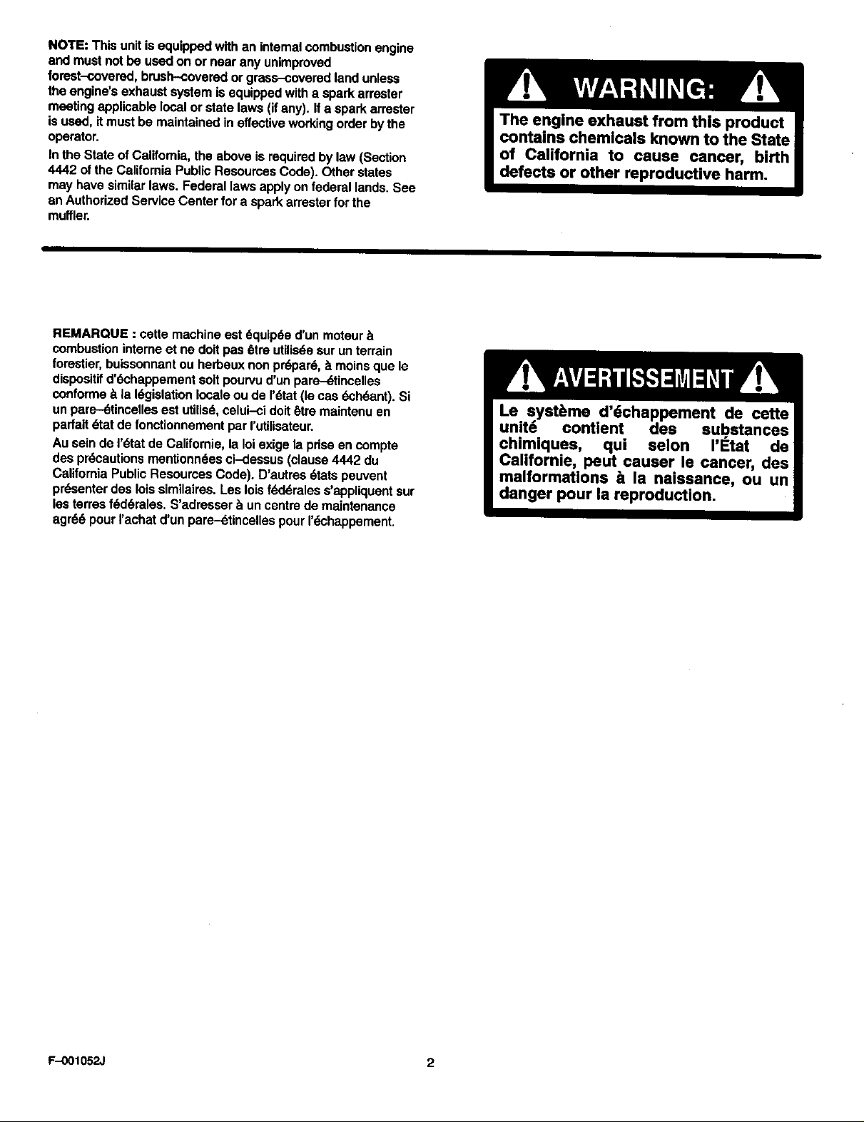
Le syst_me d'dchappement de cette
unit6 contient des sub.stances
chimiques, qui selon I'Etat de
Californie, peut causer le cancer, des
malformations ta la naissance, ou un
danger pour la reproduction.
F-0010_ 2
Page 3
_/
1
+t
4 (67_} 4
5 (71071)
_'_9 3 I
_7(71037) 6 (71060) /
6 (71060)
2_
7 (71037),,,
4
,/1
+ 5 (71071)
f/4 (6751)
3
10
_4
!1
_7
0
F-OO1052J 3
6
5 1
5
/
Page 4
Z 8
5
4
4
Io
2
f
2 3
//
8 7
/2
3
1
F-OO1052J 4
2 5
Page 5
/3
14
2
6_
7
!0
13
12
16
17
15 ¸
\
3
10
1
6
2
5
/8
F-O01052J .5
Page 6
/9
2O
5
\
/'.62cm '
, //
2/
23
22
4
F-OO1052J 6
Page 7

24
2- 6751 2- 71060
2- 9524 2- 3943
3- 586280
©
©
3- 71071
©
2- 71071 2- 71037
G©
2- 73826
D@
3- 71038
1- 304438 1- 318486 1- 6219
F--OO1052J 7
Page 8

CONTENTS
PRODUCT INFORMATION 8
OWNER'S INFORMATION B
INTERNATIONAL PICTORIALS 9
ASSEMBLY 11
OPERATION 11
MAINTENANCE 14
MAINTENANCE CHART 14
TROUBLE SHOOTING CHART 17
TWO YEAR LIMITED WARRANTY
Murray,Inc.warrantstothe originalpumhaser
that thls unit shallbe _ea from defectsin
matedaiandworkmanshipundernormaluse
andservicefor a pedodof Two (2) Year from
thedate ofpurchase;however,thiswarran_
doesnotcoverengines,accassodes(suchas
electricstarters)and NormalWear Parts(except
as notedbelow)asthe companiesthat
manufacturethese itemsfumishtheirown
warrantiesandprovideservicethroughtheir
atdhodzedfieldservicefacilities.Foradditional
Information, see thewarrantiescovedngthese
parUcularparts.If youare uncertainwhether
ycurunitcomains oris eduipped withone or
moreof these parts,coosuityourdealerpdorto
pumhase.Subjecttothe termsand conditions
notedinthis limited Warranty,we shait,atcur
option,repairor replaceat nocostto the original
purchaserany partcoveredbythisUmited
Warrantydudngthe applicablewarrantypedod.
NormalWear Partsare definedas ddvsbelts,
augers,shear pins,tiresand headlights.These
partsare warrantedtobe free fromdefectsin
matedai andworkmanshipas deliveredwiththe
product.Anyclaimfor repairor replacementof
NormalWear Partsmustbe madewithinthirty
(30) days ofthe date ofpurchase.No claims
involvingdamagecaused from rnatedaluse,
abuseor misusewillbe honored.
ThisMurray,Inc.Two (2) Year Limited
Warranty isyourexclusiveremedy;however,
thiswarrantyis voidor doesnotapplyto any
unitthat has been tampered with,altered,
misused,abusedor usedfor rentalorother
commercial and/orprofessional
(non-homeowner)uses.Yourwarrantydoesnot
coverminor mechanical adjustmentswhichare
notdueto any defectinmaterial or
workmanship.Forassistanceinmaking such
adjustments,consultyourInstructionBook.
Tomake a claimunderthis Murray,Inc.TWO(2)
Year Umited Warranty, returnthe unit(orif
authorizedIn advance, the defectivepart)along
withyourproofofpumhasetoan Authorized
CenterP_r you.To focetathe neerast
AuthorizedServiceCenter,callthe CentralPads
DistributorforyOUrareashowninthelist
providedwithyourunitorcheck the YellowPage
listingsInyourlocaltelephonedirectory.Ifyou
returnthe entireunit,we willrepairthe unit. Ifwe
au_odxa the returnofthe detectivepartonly,we
willeitherreplaceor repairthe part.ThisMurray,
Inc.Two (2) Year Limited Warrantygivesyou
specificlegalrights,and youmayalsohave
otherdghtswhichvaryfrom statetostate, This
LimitedWarranty Is given in lieuof ell other
expressed end Implied warranties Including
the Implied warranty of merchantability and
warranty of fitness for a pertlcutar purpose. If
you needadditionalinformation on this wdttan
warrantyorassistancein obtainingservice,
write:
MURRAY CANADA, INC.,
Factory Customer Service
1195 Cou_eyperk Drive East
Miseisasuga, Ont. L5T-1R1
1-800-661-6662,
PRODUCT INFORMATION
The owner must be certain that all the product
information is Included with the unit. This
Intormstfon Includesthe INSTRUCTION
BOOKS, the REPLACEMENT PARTS and the
WARRANTIES. This informaiton must be
inoleded to make sure state taws and other _ws
are followed.
OWNER'S INFORMATION
This instruction book is wdttan for a person with
some mechanical ability. Like most service
books, not all the steps are described. Steps on
how to loosen or tighten fasteners are steps
anyone can follow with some mechanical ability,
Read end follow these instructions before you
use the unit.
Know your product: If you understand the unit
and how the unit operates, you will get the best
performance. As you read this manual, compare
the illustrations to the unit. Learn the location
and the function of the controls. To help prevent
an accident, follow the operating instructions
and the safety rules. Keep this manual for future
reference.
IMPORTANT:Manyunitsare notassembled
and are soldincartons,it Is the responsibilityof
the ownertomake surethe assemblyinstruc-
tions inthis manualare exactlyfollowed. Other
unitsare pumhasedinan assembledcondition.
On assembledunits,it isthe responsibilityofthe
ownerto make surethe unit iscorrectly as-
sembled.The ownermustcarefullycheckthe
unitaccordingto the instructionsinthismanual
beforeitIstirstused.
WARNING: Look fer this symbol to indicate
important e|detyprecautions, This symbol
Indicates: "Attention! Become AlertI Your
Safety Is At Risk."
Responsibility Of The Owner
The responsibility of the owner Is to
follow the Instructions below.
1. Carefully read and follow the rules for safe
operation.
2. Followall theassemblyandpreparation
instmcSoos.
3. Inspect the unit.
4. Make surethat the operatorofthe unit
knowshowto correctly use allstandard
and accessoryequipment.
5. Operatethe unitonlywithguards,shields,
and othersafety itemsinplaceand woddng
correctly,
6. Correctlyadjustthe unit.
7. Servicethe unitonlywith authorizedorap-
provedreplacementpads.
8. Completeall maintenanceonthe unit.
Environmental Awareness
• Do notfill the engine'sfueltank completely
full.
• Drainfuel foroff-seasonstorage_
• Use onlyunleadedgasoline.
• Service the aircleanerreguledy.
• Changeoilregutarly.Use5W-30 oil.
• Tune-up theengineregularly.
• Keepequipmentinefficientoperating
condition.
• Disposeofusedengineoilproperly,
F-001052J 8
Page 9

INTERNATIONAL PICTORIALS
IMPORTANT:The following pictorials are Io-
¢cted on your unHor on Iltorcturesupplied
with the product. Before you operate the
unit, learn and understandthe purpose for
each pictorial.
Safety Warning Symbols
25
DANGER
Avoid Injury From
Rotating Auger. Keep
Hands, Feet And
Clothing Away.
DANGER DANGER
Thrown Objects. Thrown Objects.
Keep Bystanders Away. Keep Bystanders Away. WARNING
IMPORTANT
Read Owner's Manual
Before Operating
This Machine.
m
DANGER
WARNING Before Unclogging
Hot Surface STOP Discharge Chute[
ControlAnd Operat_ols (_ _ _) _
Slow Fast Electric Start Engine Start Engine Run Engine Off
0 I I,I I-I N
Engine Stop On Choke Off Choke On Neutral Forward
Stop The Engine
Reverse Throttle Primer Button Ignition Key Ignition Off ignition On
Push To Engage
Electric Starter Engage Auger Clutch
Discharge LEFT Discharge RIGHT Drive Clutch Fuel Oil Fuel Oil Mixture
Auger Collector Discharge DOWN Discharge UP
0
Weight Transfer
Lift Handle To Engage
F-001052J 9
Weight Transfer
Depress Pedal To Disengage
Transmission
Insert To Run, PullOut To Stop.
Ignition Key
Page 10

Safe Operation Practices for Snow Throwers
As Recommended By: American National Standards Institute.
IMPORTANt': Safety standards require operator
presence controls to mir_ze _ dsk of injury.
Your snow thrower is equipped with such con-
trcls. Do not attempt to defeat the function of the
operator presence control under any circum-
stances.
Training
1. Read the opem_ng and service instruction
manual cerafdily. Be thoroughly familiar with
the controls end the proper use of the equip-
ment. Know how to stop the unit and disen-
gage the controls quickly.
2. Never allow children to operate the equip-
ment. Never allow adults to operate the
equipment without proper instruction.
3. Keep the area of operation clear of all per-
sons, particularly small children and pets.
4. Exercise eau_on to avoid slipping or falling
especially when operating in reveme,
Preparation
1. Thoroughlyinspectthearea wherethe equip-
mentisto be usedand removeall doormats,
sleds,boards,wires,endothorforeignob-
its.
2. Disengageallclutchesbeforestartingthe en-
gine(motor),
3. Do not operatetheequipmardwithoutwear-
ingadequatewinterouter garments,Wear
footwearthatwill improvefoo_ngon slippery
surfaces.
4. Handle fuel with care; it is highly flammable.
a. Usaan approvedfuelcontainer.
b. Neverremovefuel tank cap oredd fuel to
a runningengine (motor)or hot engine
(motor).
c. Fillfuel tankoutdoorswith extremecare.
Never fillfuel tank indoors.
d. Replace fuee cap securely end wipe u_
spilled fuel.
e. Never store fuel or snow thrower with fuel
in the tank inside ot a building where
fumes may reach an open flame or spark.
f, Check fuel supply before each use, allow-
ing space for expansion as the heat of the
engine (motor) and/or sun can cause fuel
to expand.
5. For all unitswith electric starUng motors use
electric starting extension cords certified
CSA/UL. Use only with a receptacle that has
been installed in accordance with local in-
spection authorities.
6. Adjust the snow thrower height toclear gravel
or crushed rock surface.
7,
Neverattemptto makeany adjustments
_ thae_ne (motor)is rur_._ (except
when specificallyrecommendedby manufac-
turer).
B.
Leeengine(n_toz) andsnowthrower adjust
to outdnortemparatursabeforestartingto
clear snow.
9.
Alwayswearsafetyglassesoreye shields
duringoperationorwhileperformingan ed-
juslmontorrepair to protecteyesfromforeign
objectsthatmay be "_nrownfromthe snew
thrower.
Opemtlon
I. Do notoperatethis machineifyouaretaking
drugeoro_r med'_..st_nwi't_h cancauae
drowsinessor affectyourabilityto operate
thismachine.
2. Donct uae this machine ifyeg are mentaity
or physicallyunabletooperatethis machine
safely.
3. Donotputbendsor feetnearor underrotat-
ingparts. Keepclearof the dischargeopen-
ingat all times.
4. Exerciseextremeca_on whenoperatingon
or crossinggravelddves,walksor roads.
Stayalertfor hiddenhazardsortraffic.
5. Aiters_ldnga foreignobject,stopthe engine
(motor),removethewirefromthe sparkplug,
thoroughlyinspectsnowthrowerfor any
damage,andrepairfiledamagebeforere-
starlingandoperatingthe snowthrower.
6. If the unitshouldstartto vibrateabnom'Blly.
stopthe engine(motor)andcheckimmedi-
atelyforthe cause.VibrationIsgenerallya
warningoftrouble.
7. Stopthe engine(motor)wheneveryouleave
the operatingpoaltion,beforeuncloggingthe
augar/impallarhousingordischargechute
andwhenmakingany repairs,edjuslments,
or inspections.
8. Wbe_ desKmg,repairing,orlus_g, make
certaintheaugariimpallorandall moving
partshavestoppedandall controlsaredis-
engaged.Disconneofthe sparkplugwireand
keep thewire awayfromthe sparkplugto
preventaccidentalstarting.
9. Takeallpassible precautionswhen leaving
the snowthrower unattended.Disengagethe
auger/impeller,stopengine(motor),and re-
movekey.
10. Donot runthe engine(motor)indoors,except
whensta_ng the engine(motor)andfor
transportingthe snowthrowerin oroutof the
building.Open theoutsidedoors;exhaust
fumesare dangerous(containingCARBON
MONOXIDE,an ODORLESSandDEADLY
GAS).
11. DOnot clear snow across the face of slopes.
Exerdsa extreme cau_on when chang
direction on slopes. Do not attempt to clear
steep slopes.
12. Never operate the snow thrower without
proper guards, plates or other safety protec-
tive devices in place.
13. Never ope_ta tbe snow thrower near enclos-
ures, automobiles, window wells, drop-olts,
the like without proper adjuslment of the
snow discharge angle. Keep children and
pets away.
14. DOnot ovodoad the machine capacity by at-
tempting to deer snow e.ttoo taeea rata.
15. Never operate the machine at high transport
speeds on slippery surfaces. Look behind
end use care when bacl,_m_Jup.
16. Never direct discharge at bystanders or allow
anyone In front of the unit.
17. E/ksengagepower to the conector/=mpetier
when snow thrower is transported or not in
use.
18. Use onlyattachmentsand accessadesap-
provedbythemanufacturerofthe snow
thrower (suchastire chains,elestdcstartkits,
19. Neveroperatethesnowthrower without good
visibilityor lighLAlwaysbe sureof yourfont-
ingend kespatirmhok:len thehand_es.
Walk;neverrun.
20. DOnotover-reach.Keep properfootingand
balance eeaUtimes.
21. Exercisecau_onifoperatingon steepslop-
ingsurfaces.
22. This snowthrowerisforuse onsidewalks,
drivewaysandothergroundlevelsurfaces.
23. DOnot usethe snowthrower onsurfaces
abovegroundlevelsuchas roofsof resi-
dences,garages,porchesorothersuch
structuresor buildings.
Maintenance And Storage
1. Checkshearboltsandotherboltsatfrequent
intanralsfor propertighthsssto be surethe
equipmentis in safewoddngconcli_on.
2. Neverstorethe snowthrowerwithfuel inthe
tankinsidea buildingwhereJgnJtiorl sources
are presentsuchashotwater andspace
heaters,clofbesdryers,andthelike.Allow
the engine(motor)to coolbeforestodng in
any enclosure.
3. Alwaysreferto operator'sguideinstructions
forimportantdetailsifthesnowthrower isto
be storedfor anextendedpedod.
4. Maintainorreplacesafetyandinstructionla-
beis,asnecessary.
5. Runthe snowthrower a fewminutesafter
throwing snowtopreventfreeze-up ofthe
auger/impeller.
F-001052J 10
Page 11

ASSEMBLY
Readand followtheassemblyand adjustment
i_s foryoursnowthrower.Allfasteners
are inthe partsbag. Donot discardany parts or
materialuntilthe unitisassembled.
A WARNING: Before doing any
NOTE: In this instruction book, left and right
describe the location of s pert from the oper-
ator's position behind the unit.
NOTE: Torque is measured in foot pounds
(metric N.m). This measurement describes
how tight a nut or bolt must be. The torque is
measured with a torque wrench.
NOTE: Illustrations begin on page 3.
NOTE: To assemble the following loose
parts, use the fasteners shown at full size in
Figure 24.
Tools Required
1 Knife
1 Pliers
1 1/2 inchadjustableopenendwrenches
1 9/16 inchadjustableopenendwrenches
1 3/4 inchadjustableopenendwrenches
1 Measuringtape or ruler
1 Screwdriver
How To Remove The Snow Thrower
From The Carton
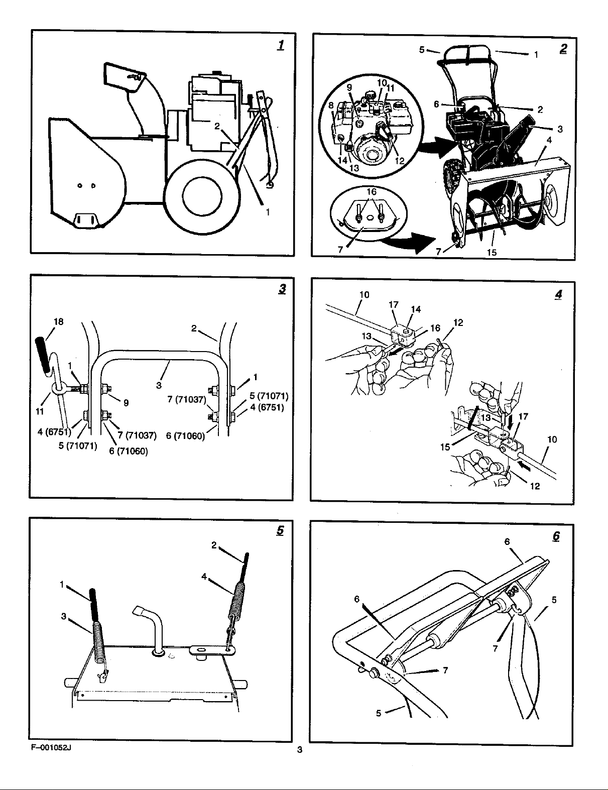
1. (Figure/)The snowthrower b shownin the
2. Locateall partsthatare packedseparately
3. Removeand discardthepackingmaterial
4. Cutdownallfourcomersof the cartonand
5. Holdontothe lowerhandle andpullthe snow
6. Removethe packingmaterial fromthe han-
7. Cutthe tiesthat secure _e clutch control
How TO Assemble The Handle And
Crank Assembly
1. (Figure 3) Loosen, but do not remove, the
2. (Figure 2) Put the shift lever (6) into first
3. (Figure 3) Raise the upper handle (2) to the
4. Install the screw (4), flatwasher (5), lock-
assembly or maintenance to the
snow thrower, remove the wire
from the spark plug.
shippingposition.
andremovefrom thecadon.
fromaroundthe snowthrower.
laythe sidepanelsfiat.
thrower offthe carton.
CAUTION: DO NOT back over cables.
dleassembly.
cables (1) tothe lower handle (2). Move the
cablesawayfrom the motor frame.
fasteners (1) in the upper holes of the lower
handle.
forward position.
operating position.
NOTE: Make sure the cables are not
caught between the upper and lower han-
dle.
washer (6), end hex nut (7) into the bottom
holes on each side of the handles. Make
sure fasteners in the bottom holes are tight.
F-001052J
5. (Flgure4)Cutthecabletiethatholds_e
upper crank rod (10) to the handle. Careful-
ly remove the cotter pin (12) and clevis pin
(13) from the yoke (17) on lower end of the
upper crank rod (10). Do not remove the
universal joint pin (14).
NOTE: Make sure the universal Joint pin
(14) and the universal joint (16) ere
mounted in the yoke (17). If not, secure
the universal joint (16) inside the yoke
(17) with the universal Joint pin (14).
6. Hole the universal Joint (16) in place and
slide the upper crank rod (10) down through
the eye bolt (11) and onto the yoke end of
the lower crank rod (15).
7. Secure the upper crank rod (10) to the low-
er crank rod (15) with clevis pin (13) end
cotter pin (12). Spread the ends of the cot-
ter pin (12) to lock in place.
8. (Figure 3)'tighten nut (9) on eye bolt (11).
Make sure eye bolt (11) is properly aligned
and the crank (18) can freely rotate.
9. "lighten all handle fasteners,
Check The Cables
1. (FlgureS)Chec_thetracflondriveeeble
(1) and the auger drive cable (2). If the bot-
tom of the cables have become discon-
nected, reinstall the cable springs. Make sure
the long spring (3) is attached to the traction
drive and the short spring (4) is attached to
the auger drive.
2. (Figure 6) If the top of the cables (5) have
become disconnected from the drive levers
(6), attach the cables (5) to the "Z" fitting
(7).
How To Assemble The Snow Chute
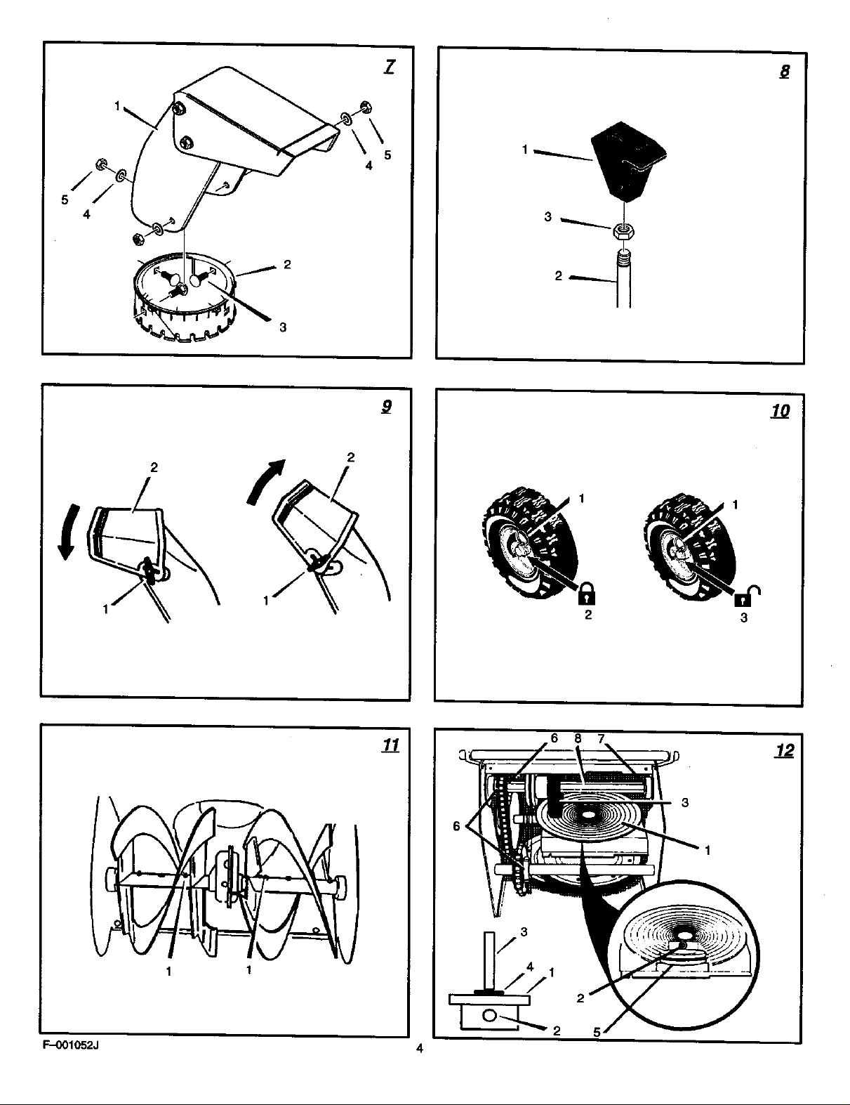
(Figure 7)
1. installthe snow chute(1) ontothesnow
chute flange (2). Alignthe three holesinthe
snow chute (1) withthe holesinthe snow
chute flange (2).
2. Fastenthe snow chute (1) to the snow
chute flange (2) withcarriage bolts (3),
washers (4) end nuts (5). Make surethe
carriage bolts (3) are installedwiththe head
ofthe bolts (3) onthe insideof the snow
chute flange (2) as showninthe illustration.
3. Makesureallfastenersaretight.
NOTE: DO NOT overtighten the fasteners.
How To Install The Shift Knob
(Figure 8)
1. Install the hex jam nut (3) onto the end of
the speed shift rod (2).
2. thstall the knob (1) outo the speed shift rod
(2) until the knob (1) is snug against the he](
jam nut (3). To look in position, tighten the
hex jam nut (3) against the knob (1).
How To Check The Cables
The traction drive cable and the auger drive
cable are adjusted at the factory. Before operat-
ing, make sure adjustment of the cabins have
not changed. See =How To Check And Adjust
The Cables" in the Maintenance section.
How To Set The Skid Height (Figure 2)
The snow thrower is equipped with height ad-
justable skids (7) mounted on the outside of the
auger housing (4), To adjust the height of the
11
skids, see "How ToAdjust The Height Of The
Skids" in the Maintenance section.
How To Prepare The Engine
Note: The engine was shipped from the fac-
tory filled with oil Check the level of the oil.
Add oil as needed. Engine does not contain
GASOLINE.
A ARNING: Follow the engine
when adding gasoline to the engine. When
Check the oil, See the engine manufacturer's
instructions for the type of fuel and oil to use.
Before you use the unit, read the information on
safety, operation, maintenance, and storage.
manufacturer's Jnstruutlons for the
type of fuel and oil to use. Always
use a safety fuel container. Do not smoke
inside an enclosure, do not fill with gaso-
line. Before you add fuel, stop the engine.
Let the engine cool for several minutes.
OPERATION
NOTE: Itiustrations begin on page 3.
Know Your Snow Thrower (Figure 2)
Readthis InstructionBookandsafetyrulesbe-
foreoperationthe snowthrower. Comparethe
Ulustrafionwithyoursnowthrowerto familiarize
yourselfwiththelocationofvariouscontrolsand
adjustments.
Traction Drive Lever (1) - Select the forward or
reverse direction of travel.
Crank Assembly (2) - Changes the direction of
the discharge chute.
Discharge Chute (3)- Changes the distance the
snow is thrown.
Auger Drive Lever (5)- Startsandstopsthe au-
gerandimpeller(snowgatheringandthrowing).
Speed Shift Lever (6) - Selects the speed of the
snow thrower.
Height Adjust Skid (7) - Adusts the ground
clearance of the auger hous ng,
Ignition Key (8) - Must be inserted to start the en-
g=ne.
Primer Button (9) - Injects fuel directty into the
carburetor for fast starts in cold weather.
Electric Start Button (10) -On electric start mod-
els, used to start the engine,
Switch Box (11) - On electric start models used
to attach a 120 volt e ectric power cord,
Recoil Starter Handle (12) - Use to manually
start the engine.
Throttle Control (13)- Controls the speed of the
engine.
Choke Control (14) - Use to start a cold engine.
How To Control
The Discharge Of The Snow
A WARNING: Never direct the dis-
A ARNING: Always stop the engine
charge of snow toward bystanders.
before unclogging the discharge
chute or the auger housing and be-
fore leaving the snow thrower.
Page 12

1. (Figure 2) Turn the crankm$_mmbly(2) to
changethedischarge dlrec_onofthesnow.
2. (Figure 9) Loosenthe wing knob (1) onthe
chute deflector (2).
3. Movethe chute deflector (2) upfor more
distanceordownforleas distanc•.
4. "nghtanthe wing knob (1).
How To Stop
The Snow Thrower (Figure 2)
1. To stop discharging snow, release the auger
drive lever (5).
2. To stop the wheels, release the traction
drive lever (1).
3. To stop the engine, push the throttle control
lever (13) to offand remove the Ignition key
(S).
How TO Go Forward or Backward
(Figure 2)
1. Tochangethe grcundspeed, firstrelease the
traction drive lever (1) andthen moveth•
speed shift taver (6) tothe desired speed,
2. Groundspeed is determinedby•now condi-
tions.Selectthe speed bymovingthe •poed
• hift lever (6) intothe appropriatenotchon
the shift leverplate.
Speed1, 2 Wet,Heavy
Speed3 Light
Speed4 VeryLight
Speed5, 6 Transportonly
3. Togoforward,engagethe traction drive
lever (1). Maintaina firmholdonthe handle
asthe snowthrower startsto move forward.
Guidethe snowthrower by movingthe ban-
dieeither left or dght. Donot attempt to push
the snowthrower.
4. Togobackward,releasethe tractor drive
lever(1).
5. Movethe speed shift lever(6) intoeith•r
firstorsecond reverse.
6. Engagethe traction drive lever (1).
IMPORTANT: DOnot move the speed shift
lever (6) while the traction drive laver (1) i•
engaged.
How To Throw Snow (Figure 2)
1. Engageth• auger drive lever (5).
2. Tostopthrowingsnow,release the auger
drive lever (5).
A ARNING: The operation of any
How To Use The Wheel Lockout Pin
snow thrower can result In foreign
objects being thrown Into the eyes,
which can result in severe eye damage.
Always wear safety glease• or eye shields
while operating the snow thrower. We rec-
ommend standard safety glasses or use e
wide vision safety mask over your glasses.
(Figure 10)
1. _ left hand wheel is secured to th• axle
with a klick pin (1). This unit was shipped
wi_ this kllek pin (1) through the wheel hole
In the tacked position (2).
2. For ease of maneuverability in light snow
conditions, change th• klick pin (1) to an
unlocked position (3).
F-001052J
3. OLsnoor,.eotthe kRokPin(1) fromthewheel
locked position (2). Pushthe kllck pin (1)
through the unlockedaxle holeonly. The unit
isnowinthe singlewheeldriveunlocked
position (3).
Before Starting The Engine
1. Before you service or stad the engine, famil-
iarize yourself with the •now thrower. Be
sure yon understand the function and loca-
tion of all controls.
2, Check the tension of the clutch cable before
starting the engine. See "How To Adjust Th•
Clutch Cable" in the Maintenance section of
this manual.
3. Make sum that all fasteners ere tight.
4. Make sure the height adjust skids are proper-
ly adjusted. See "How To Adjust The Height
Of The Skids" in the Maintenance section of
this manual.
5. Check the air pressure in the tires, The cor-
rect air pressure is 14 PSI (1 BAR) to 17 PSI
(1,25 BAR), Do not exceed the maximum
amount of air pressure shown on the side of
_e tire.
How To Stop The Engine (Figure2)
Tostopthe engine,move the throttle control
(3) to thestoppositionandremovethe Ignition
key (8). Keepth• Ignlttan key (8) ina safe
place. The enginewillnotstartwithouttheIgni-
tion key (8).
How To Start The Engine (Figure2)
Models equipped with an Electric Starter
NOTE: An electric starter Idt can be added to
recoil •tart engines. Electric starter kits am
available from your nearest authorized ser-
vice center,
A ARNING: The starter is equipped
with a three-wire power cord and
plug and Is designed to operate on
120 volt A,C. household ourront. The power
cord must be properly grounded at ell times
to avoid the poaslbllfty of electrical •hock
which can Injure the operator. Carefully fol-
low all instructions in the "How To Start The
Engine" section. Make sure that your house
wiring is • three-wire grounded system, if
you ere not sure, ask a licensed electrician.
If your house wire system Is not a
three-wire grounded system, do not use
this electric starter under any conditions. If
your system is grounded but a three-hole
grounded receptacle is not •vail•ble to start
the engine, have a three-hole grounded re-
ooptacle installed by a licensed electrician.
To connect a 120 volt A.C. power cord, al-
ways connect the power cord to the •witch
box (11) on the engine first. Then, plug the
other end into the three-hole grounded re-
nsptecle. When disconnecting the power
cord, always unplug the end from the
three-hole grounded receptacle first.
How To Start A Cold Engine (Figure 2)
1. Checktheengineoil.
2. Fillthe fueltankwithregular unleadedpetrol.
See "HowTo PrepareThe Engine'.
12
ENGL/SH
3. Make sum the trectton drive laver (1) and
the auger drive lever (5) are in the disen-
gaged (released) position.
4. Move th• throttle €ontrol (13) to the fast
position.
5. Ins•rt the Ignition key (8) into the ignition
slot. Make sum the IgnIflon key (8) •naps
into piece. Do not turn the ignition key (8).
Remove th• •xtra ignition key and keep in a
sets place.
6, Move the choke control (14) to the full
choke position.
7. (ElectricStart)Connectthepow•rcordto
the switch box (11) located on the engine,
8. (Electrio Start) Plug the other end of the
power cord into a three-hole, grounded 120
VOLT, A.C. receptacle. (See the WARNING
in this section).
9. Push the primer button (9). Every time you
push the primer button (9), wait two sec-
onds. For the number of times required to
push the primer button (9), see the engine
manufacturer's instructions.
10. (Electric Start) Push on the electric start
button (10) untilthe engine starts. Do not
crank for more than 10 seconds at a time.
The electric starter is thermally protected. If
the electdc starter overheats, it wil!automati-
cally stop and can only be restarted when it
has cooled to a safe temperature. A wait of
about 5 to 10 minutes is required to allow the
electric starter to cool.
11.(Recoil Start) Rapidly pull the recoil starter
handle (12). Do not allow the recoil starter
handle (12) to snap back. Slowly return the
recoil starter handle (12).
12.1f the engine does not •tart in 5 or 6 tdes,
See the "Trouble Shooting Cha_ Instruc-
tions.
13. (Electric Start) Wh•n the engine starts, re-
lease the electric start button (10) and
move the choke control (14) to 1/2 choke
positlan. When the engine runs •monthly,
move the choke control (14) tothe off posi-
tion.
14. (Electric Start) First disconnect the power
cord from the three-hole receptacle. Then,
disconnect the power cord from the swltah
box (11).
NOTE: In temperatures below O°F, allow
the engine to warm up for several minutes
before blowing •now,
15.Whec throwing snow, always run the engine
with the throttle control (13) in the fast posi-
tion.
indoors or th enclosed, poorly ven-
,_lk WARNING: Never run the engine
tilated areas. Engine exhaust con-
tales carbon monoxide, an odorless and
deadly gas. Keep bands, feet, hair end
loose clothtag away from any moving parts
located on the engine or the snow thrower.
The temperature of muffler end nearby
area• mey exceed 150°F. Avoid these
areas.
How To Start A Warm Engine (Figure 2)
If an engine has been running and is stillwarm,
leave the choke control (14) in the off position
and do not push the primer button (9). If the
engine tail• to start, folk_w _ inst_s "How
To Star A Cold Engine".
NOTE: Do not use the primer button (9) to
start • warm engine.
Page 13

How TOStart An EngineW'_h A FrozenElectric
Starter (Figure 2)
If the electdc starter is frozen and wilt not fum
the engine, follow the instructions below.
1. Pug out the recoil starter handle (12) as far
as possible.
2. Quickly release the recoil starter handle
(12). Ntow the r_oll starter handle (12) to
snap beck against the recoil starter.
If the engine still fails to start, repnet the two pre-
vious steps until the engine starts. Then, contin-
ue with the directions =How To Start A Cold
Engine".
To help prevent the possible frseze--up of the
recoil starter and of the engine contruis, proceed
as foitows s_tm each snow removal JGo.
1. With the engine running, quickly pull the re-
coil Starter handle (I 2) three or four times
with e continuous full arm stroke. This will
produce a loud clettadng sound that is not
harmful to the engine or starter.
2. Stop the engine. Wipe all snow end moisture
from the carburetor cover, control levers and
cables. ALsomove the throttle Gontrol (13),
©hoke control (14), and recoil starter han-
dle (12) several times.
How To Remove Snow or Oebds From
The Auger Housing (Figure2)
A ARNING: Do not attempt to re-
1. Releasethe auger drive lever (6).
2. Movethe throttle control (13) tothe stop
3. Remove(donet turn)theIgnltloo key (8).
4. Disconnec_the sparkplug wire.
5. Donot placeyourhandsinthe auger hous-
Snow Throwing Tips
1. Formaximumsnowthrower efficiency,
move snow or debristhat may be-
©omelodged In auger housing
without taking the following preeautlen$.
position.
Ing (4)or the discharge chute (3). Usea
prybarto removeanysnowor debds.
changethe groundspeed,NEVER change
the enginespeed, The engine isdesignedto
delivermaximumperformanceat full throttle
and most be runin the fastpositionatall
times. Indeep, freezing,or wet snow,reduce
forwardspeed.Ifthe wheelsslip,alsoreduce
forwardspeed,
ENGL/SH
2. Mostefficientsnowthrowing is accomplished
when the snowisremovedimmediatelyafter
iffalls.
3. Forcompletesnowremoval,slightlyovedap
eachpreviouspath,
4. Wheneverpossible,dischargethesnow
downwind.
5. Fornermat usage,set the skidsso thatthe
scraperbar is 1/8"abovethe skids. Forex-
tremelyhard-packodsnowsurfanes,adjust
the skidsupwardso that the screporbet
touchesthe ground.
6. Rocksand gravelmustnotbe pickedupand
thrownbythe machine.On gravelorcrushed
rocksurfaces,setthe skidsat I-I/4 inchbe-
lowthe scraperbar.See "HowToAdjustThe
HeightOf The Skids"inthe Maintenance
section.
7. Afteree,chsnowthrowing_b, allow the en-
gineto idlefor afew minutes.The snowand
accumulatedicewill meltoftthe engine.
8. Cleanthe snowthrower after eachuse,
9. Removeice,snowand debdsfrom the entire
anow thrower. Rushwithwaterto removeall
saltor otherchemicals.Wipesnowthrower
dry.
F--001052J 13
Page 14

CUSTOMER RESPONSIBILITIES
SERVICE RECORDS
MAINTENANCE CHART
Fill In dates as you Before Rrst Every Every
complete regular Each 2 . .. Ezo Each Before
service. Use Hours Hours Hours Hours Season Storage SERVICE DATES
Change Engine Oil _/
Check Spark Plug _/ ._
Check Fuel N/
Check Auger Clutch Cable Adjustment
(See Cable Adjustment) _ N/
Lubdcate Disc Ddve Plate Zsrk
(See Maintenance) _/
Lubdcete Auger Shaft
(See Shear Bolt Replacement) "J "_
very
MAINTENANCE
NOTE: Illustrations begin on page 3.
Usethe followingmaintenancesectiontokeep
you_unit_ngoodoperating conditk>n.._lthe
m_ntanance informationfor the engine isinthe
enginemanufacturer'sinstructions.Beforeyou
startthe engine,readthis book.
A ARNING: Before you make an In-
General Recommendations
The warrantyon this snowthrowerdoesnotcov-
eritemsthathave beensubjectedto operator
abuseor negligence.Torscalvofullvalue from
the warranty,the operatormustmaintainthe
snowthrower as instructedinthis manual.
Someadjustmentsmustbe made periodicallyto
pmpsdymaintainthe snowthrower.
After Each Use
• Check for any loose or dan',aged parts.
• Tighten any loose fasteners.
• Check and rnaJntsinthe auger.
spantion, adjustment (except
carburettor), or repair, disconnect
the wire from the spark plug.
• Check controls to make sure they are
functioning pmpedy.
• If any parts are wom or damaged, replace
immediately.
F-001052J
NI adiustmants la the Maintenance ce_ion of
this manual should be checked at least once
each season,
As Required
The following adjustment should be preformed
more than once each season.
1. Adjust the auger ddve belt after the first 2 to
4 bourn, again at mid-eaason, and twice
each season thereafter. See "How To Adjust
The Auger Ddve Belt" in the Maintenance
section.
Lubrication
Every 10 Hours (Figure 11)
1. Lubdcatethe Zorkffttlngs (1) every tan
hourswitha grease gun.
2. Eachtimea shearboltisreplaced,the auger
shaftmustalsobe greased.
3. Lubricateall pivotpoints.
Every 25 Hours (Figure 12)
Lubdcatsthe discdrive plats (1) every25
hours,at the end ofthe season andbeforestor-
age.
1. (Figure 2) Movethe speed shift lever (6) to
firstgear.
2. Removethegasfrom the gastank. Stand
the snowthrower up onthe frontendof the
auger housing (4).
14
A ARNING: Brain the gasoline out-
3. (Figure 18) Remove the bolts (1) on each
4. Loosen the bolts (3) on each side of the bet-
5. Remove the bottom panel (2).
6. (Figure 12)Tum the disc drive plate (1)
7. To prevent the rubber friction wheel (3) from
8. Lubricate the Zerk fitting (2) with a grease
9. Remove coin (4) used in step 7. Make sure
doors, away from fire or flame.
side of the bottom panel (2).
tom panel (2).
clockwise by hand until the Zerk fitting (2) is
visible.
contacting the drlve disc plate (1), put a
coin (4) (or a shim of equal thickness) be-
twean the rubber friction wheel (3) and the
disc drive plate (1).
gun. Use a high temperature EP Moty
grease. Fill the Zerk fitting (2) only until
grease becomes visible below the bearing
assembly (5) located under the Zerk fitting
(2). DO NOT over fill. Clean all excess
grease from the friction disc hub.
CAUTION: Do not allow grease to coma
In contract with the disc drive plate (1) or
the friction wheel (3) or damage will re-
suit.
that a gap exists between the friction wheel
(3) and the disc drive plate (1).
tO.(Figure 18) Install the bottom Imnel (2).
11.Tighten the bolts (3) on each side of the bot-
tom panel (2).
12.Install the bolts (1) on each side of the bot-
tom panel (2).
Page 15

ItemsNotToLubricate(Figure 12)
1. Do not lubricate the hex shaft end sprock-
ets (6). All bearings and bushings era life-
time lubricated. For storage, put e slight
amount of 5W-30 motor o11on a cloth and
wipe the hex shaft and sprockets (6) to
prevent rust.
2. If greece or oil comes in contact with the
disc drive plate (1) or the friction wheal
(3). the friction wheal (3) can be damaged.
Make sure to thoroughly clean the disc drive
plats (1) and the friction wheal (3).
CAUTION: Any greasing or oiling of the
above components can cause contemtha-
flon of the friction wheel (3), If the disc
ddve plate (1) or the friction wheel (3) be-
come contaminated with grease or o11,
damage to the friction wheel will result.
3. The auger gear case is lubricated at the fac-
tory and does not require add'Krona!lubrica-
tion. If for some mason the lubricant leaks
out, have the auger gear case checked by a
le_;tory authorized service cectar.
How To Adjust The Height Of The Skids
(Figure 2)
Thissnowthrower isequipped withtwoheight
adjustable skids(7). These skidselevatethe
frontofthesnowthrower. For normalhardsur-
faces,suchas a paveddrivewayorwalk, adjust
the skidsasfollows.
1. Putthe snowthrower ona levelsurface.
2. Make surebeth tiresare equally inflated.
The correctair pressureis14 PSI (1 BAR)to
17 PSi (1.25 BAR). Do not exceedthe malt-
mum amountofair pressureshownon the
sideofthe tire.
3. Putthe extrashear bette (found in the parts
bag) undereach endof the scraper bar (15)
nextto theadjustable skids (7).
4. Loosenthe mounting nuts (16) that holdthe
adjustable skids (7). Tobringthe frontof the
snowthrowerdown,raiseeachadjustable
skids (7). "llghtenthemounting nuts (16).
NOTE: For rocky or uneven surfaces, raise
the front of the snow thrower by moving the
adjustable skids (7) down.
A ARNING: De certain to maintain
How To Adjust
The Scraper Bar (Figure 2)
Afterconsiderableuse,the scraper bar (15) will
becomewom. The scraper bar (155,incon-
junc_onwith the skids,mustbe adjusted toallow
1/8inchclearancebetween the scraper bar
(155andthe sidewatkor area to becleared.
t. Putthe snowthrower on a levelsurface.
2. Makesurebothtiresare equallyinflated.
3. Loosenthe carriageboltsandnuts thathold
proper ground clearance for the
area to be cleared. Objects such
as gravel, rocks or other debris, I1struck
by the impeller, can be thrown with suffi-
cient force to cause personal injury,prop
arty damageor damage to the snow throw-
ah
The correct air pressureis t4 PSi (1 BAR) to
17 PSI (1.25 BAR). Do notexceed the maxi-
mumamountofair pressureshownonthe
sidect thelira.
the scraper bar (15) to the auger housing
(4).
F-O01052J
4. Adjust thesorsw bar (15) to allow1/8 Inch
clearancebetween thescraper bar (15) and
the sidewalkorarea tobe cleared.
5. Tightan the carriage boltsand nuts.Make
surethatthescraper bar (15) is parallelwith
the sidewalkorareato be cleared.
6. Tosxtaeded the |'riaof the sor_0er bar (15),
removeand reversethe mountingofthe
scraper bar (15).
How To Check And Adjust The Cables
The tractiondrivecable andthe augerdrive
cable are adjustedatthe factory.Duringnormal
use, a cable canbecomestretchedand mustbe
checkedand adjustedasfollows,
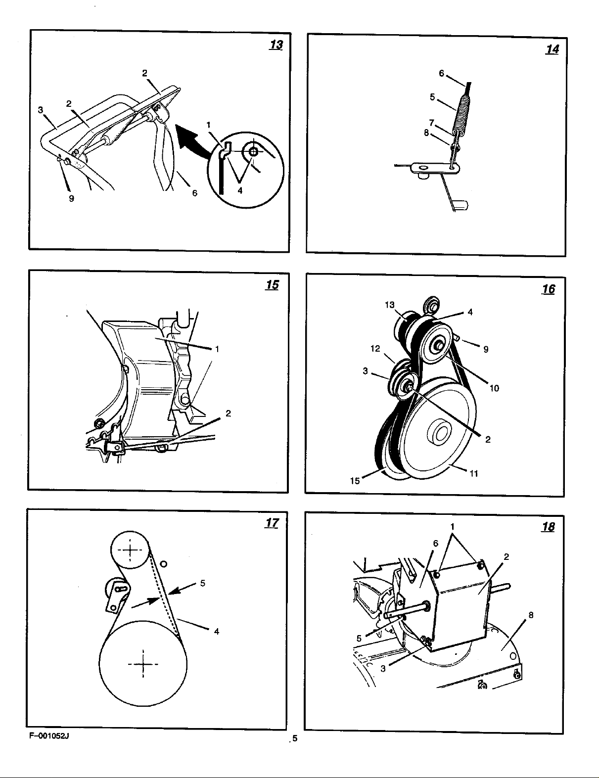
How To Check The Cables (Figure 13)
1. Tocheckforcorrect adjustment,disconnect
the "Z" fitting (1) fromthe drive lever (2).
2. Movethe drive lever (2) forwarduntilthe
drive lever stop (9) is conta_ng the handle
(3).
3. The controlcableis correctlyadjustedif the
center at the "Z" fitting (15is aligned (45
with the holeinthe drive lever (2) andthere
innodroopinthe cable.
How To Adjust The Cables
1. Removethe gasfrom thegastank. Stand
the snowthrower up onthe frontendof the
augerhousing.
A ARNING: Drain the gasoline out-
doors, away from fire or flame.
2. (Figure 13) Disconnectthe "Z" fitting (1)
from the drive lever (2).
3. (Figure 14) Pullthe springcoverupto ex-
posethe spring (5). Pushthe cable (6)
through the spring (5) to exposethesquare
end (7) onthe cable (6).
4. Hoki thesquare end (7) withpliersand ad-
JusttheIocknut (8) In oroutuntilthe excess
slackisremoved.
5. Pullthe cable (6) backthrough thespring
(as.
6. (Flgure13) Connectthe "Z" flttlng (l) to the
ddve lever (2).
NOTE: When the trecttan drive belt or the
auger ddee belt Is adjusted or replaced,
check andadjust the ceble.
How To Adjust The Belts
The beltswillstretchdudngnormal use. Ifyou
needto adjustthe belts dueto wear orstretch,
proceedas follows.
How To Adjust The Auger Drive Belt
If the snow thrower will not discharge snow,
check the adjustment of the auger drive cable,
See "How To Check And Adiost The Cables" in
the Maintenance section. If the adjustment is
correct, then check the condition of the auger
drive belt. If the auger drive belt is damaged,
replace the auger drive belt. See =How To Re-
place The Belts" in the Maintenance soc_on. If
the auger ddve belt is loose, adjust as follows.
1. Disconnect the spark plug wire.
2. (Figure 15) Remove screw (2) from belt
cover (1). Remove the belt cover (1).
15
ENGL/SH
3. (Figure 16) Loosenthe nut (2) an the Idler
pulley (3) Movethe Idler pulley (3) 1/8 inch
towardthe auger drive belt (4).
4. Tightenthe nut (25.
5. (Figure 17) Depressthe augerdrivelever.
Checkthe tensiononthe auger drive belt
(45.Incorrecte_usbnent,thea,,._gerdrive
belt (4) willdeflect1/2 Inch(5) withmoder-
atepressure.If the adjustmentis notcorrect,
repeattheadjustment.
6. (Figure 15)lnstallthebeltcover(1). _ghten
SCreW(2).
7. Checkthe adjustmentoftheaugerddve
cable.See =HowToCheckAndAdjustThe
Cables"inthe Maintenancesection.
8. Attachthe sparkplugwire.
Traction Drive Belt
The tractiond_a be_thasconstantspi_'_ pres-
sureand doesnot require anadjustment.Ifthe
tractiondrivebeltisslipping,replacethebelt.
See =HowTo ReplaceThe Belts" inthe Mainte-
nancesection.
How To Replace The Belts
The drivebelts are of specialconstructionand
mustbe replacedwithoriginalfactoryreplace-
ment belts avalla_e fromyournearectautho-
rizedservicecenter.
Somestepsrequirethe assistance of a second
person.
How To Remove the Auger Drive Belt
Ifthe auger ddvebeltis damaged,the snow
throwerwillnot dischargesnow.Replacethe
damagedbeltas follows.
1. (Flgure2)Remavethegasfromthegec
tank.Standthe snowthrowerup onthe front
end ofthe auger housing (4).
A ARNING: Drain the gasoline out-
2. Disconnectthespark plugwire.
3. (Rgure 15)Removescrew (2) from belt
4. (Figure 18)Removethebolts(5)aneech
5. Loosenthe bolts (3) oneach sideof the reo-
6. (Figure 16) Loosenthe belt guide (9). Putt
7. Loosenthe nut (2) on the idlerpulley (3).
8. Removethe oldauger drive belt (4) from
9. Installthe newauger drive belt (4) ontothe
doors,away from fire or flame.
cover (1). Removethe belt cover (1).
side ofthe motor mount frame (6),
tot'mount frame (6). The augerhousing
(8) and the motor mount frame (6) willsep-
arate,hingedby bolts (3).
the belt guide (9) awayfromthe auger
drive pulley (10).
Pul!the idler pulley (3) away fromthe auger
drive belt (4),
the auger drive pulley (10) andfrompulley
(11).Replacethe auger drive belt (4) with
an originalfactoryreplacementbeltavailable
froman authorizedservicecenter.
auger drive pulley (10) and ontopulley
(11),
10.Adjustthe auger drive belt (4). See "HowTo
AdjustThe AugerDriveBelt"inthe Mainte-
nanca section.
11.Adjustthe belt guide (9). See "HowToAd-
justThe BeltGuide"inthe Maintenancesec-
t!an.
Page 16

12.(Rgure 18)Installthebolts (5) oneach side
ofthe motor mountframe (6).
13.Tightanthe bolts (3) oneach sideofthe mO-
tor mount frame (6).
14.(Rgure 15)Installthebelt cover (1). Tighten
screw (2).
15.Checkthe adjustment of the cables.See
"How To CheckAnd AdjustTheCables"in
the Maintenancesection.
16.Connastthe sparkplugwire.
How To Remove the Traction Drive Belt
If the snow thrower will not move forward, check
the traction ddve belt for wear or damage. If the
traction drive belt is worn or damaged, replace
the belt as follows.
1. (Figure 2) Remove the gas from the gas
tank. Stand the snow thrower up on the front
end of the auger housing (4).
A ARNING: Drain the gasoline out-
2. Disconnect the spark plug wire.
3. Remove the auger ddve belt. Sea "How To
4. (Figure 16) Pull the traction drive Idler
5. Remove the old traction drive belt (13) from
6. Install the new traction drive belt (13) onto
7. Make sure the trnctlon drive Idler pulley
8. Install and adjust the auger drive belt (4).
9. Adjust the belt guide (9). Sea =How To Ad-
10. (Figure 18) Install the bolts (5) on each side
11.Tighten the bolts (3) on each side of the mo-
12. (Figure 15) Install the belt cover (1), Tighten
13.Check the adjustment of the cables. See
14.Connect the spark plug wire.
How To Adjust The Belt Guide
1. Disconnect spark plug wire.
2. (Figure 15) Remove screw (2). Remove the
3. (Figure 2) Engage the auger drive lever (5).
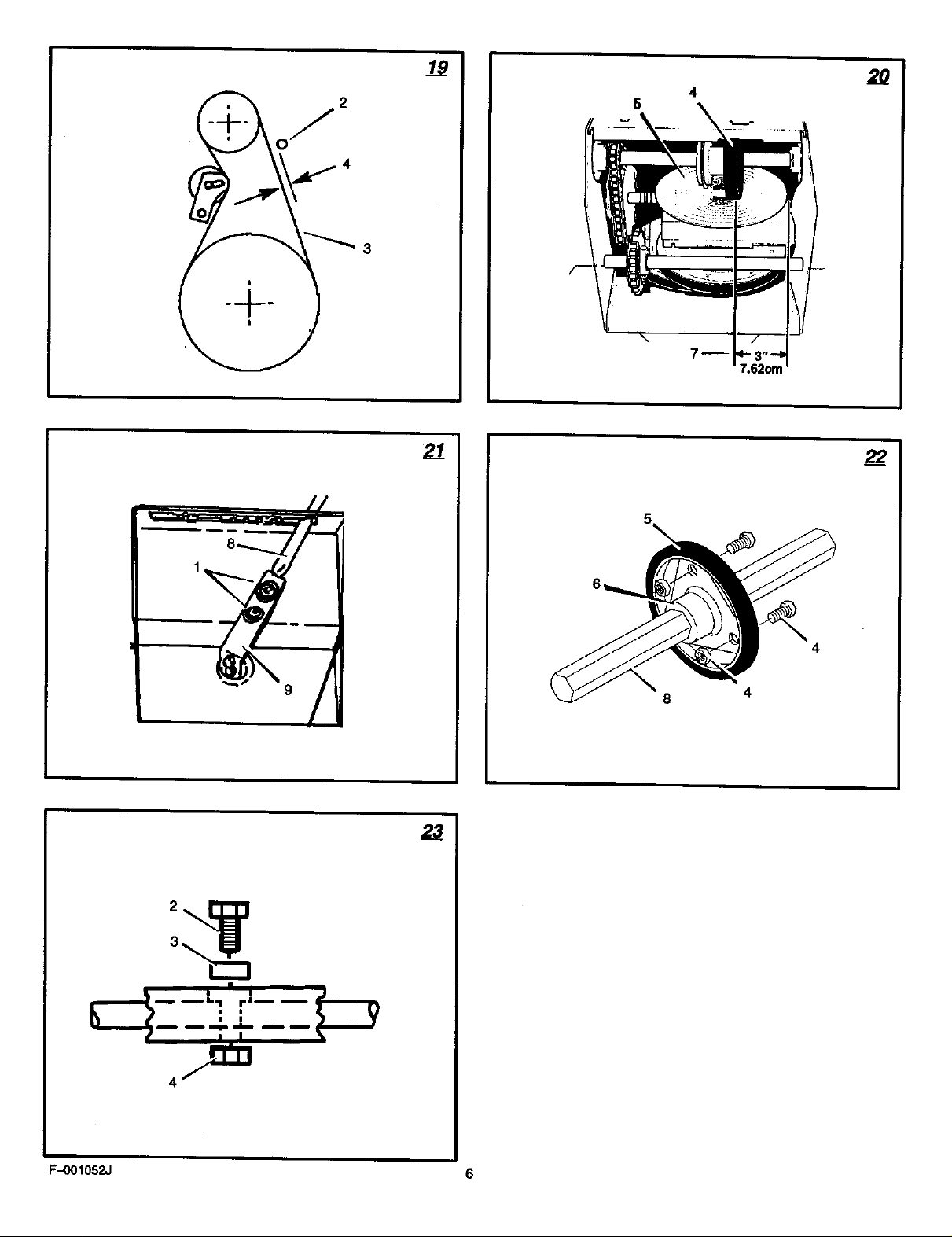
4, (Figure 19) Measure the distance between
5. If an adjustment is necessary, loosen the
doors, away from fire or flame.
Remove The Auger Drive Belt" in the Mainte-
nance section.
pulley (12) away from the traction drive
belt (13).
the traction drive pulley (14) and from the
engine pulley (15). Replace the traction
drive belt (13) with an original factory re-
placement belt available from an authorized
service center.
the traction drive pulley (14) and onto en-
glen pulley (15).
(12) Is properly aligned with the traction
drive belt (13).
Sea "How To Remove The Auger Drive Belt"
in the Maintenance section.
just The Belt Guide" in the Maintenance sec-
tion.
of the motor mount frame (6).
tor mount frame (6),
screw (2).
=How To Check And Adjust The Cables" in
the Maintenance section.
belt cover (1).
the belt guide (2) and auger drive belt (3),
The correct distance (4) is 1/8 inch (3.175
mm).
mounting bolt for the belt guide (2). Move
the belt guide (2) to the correct position
(4), Tighten the mounting boltfor the belt
guide (2),
F-001052J
6. (Rgura 16) Install the belt cover (1). Tighten
screw(2).
7. Connast 6"mspark plug wire.
How To Adjust Or ReplaceThe Friction
Wheel
How To Check The Friction Wheel
If the snow thrower will not move forward, check
the traction ddve belt, the traction ddve cable or
the fiction wheel, If the friction wheel is wom or
damaged, it must be replaced. See "How To
Replace the Fdction Wheel" in this section. If the
friction wheel is not worn or damaged, check as
follows.
1. (Figure 2) Remove the gas from the gas
tank. Stand the snow thrower upon the front
end of the auger housing (4),
A ARNING: Drain the gasoline out-
2. Disconnect the spark plug wire.
3, (Figure 18) Remove the bolts (1) on each
4. Loosen the bolts (3) on each side of the bot-
5. Remove the bottom panel (2).
6. (Figure 2) Position the iBhiftspeed lever (6)
7. (Figure 20) Nots the position of the friction
How To Adjust The Friction Wheel
1. (Figure 21) Loosen the bolts (1) on the
2. (Flgure 2O) Move the hictlon wheal (4) to
3. (FIgure21)Tightenthebolte(1)onthe
4. (Figure 18) Install the bottom panel (2).
5. Tighten the bolts (3) on each side of the bot-
6. Install the bolts (1) on each side of the bct-
How To Replace The Friction Wheal
If the _ction wheel is wom or damaged, the
snow thrower will not move forward. The friction
wheel must be replaced as follows,
1. (Figure 2) Remove the gas from the gas
2. Disconnect the spark plug wire.
3. (Figure 18) Remove the bolts (1) on each
4, Loosen the bolts (3) on each side of the bet-
5, Remove the bottom panel (2),
doors, away from fire or flame.
side of the bottom panel (2).
tom panel (2).
in the first forward gear.
wheal (4) on the disc drive plate (5). In the
correct position (7), the right outer side of
the disc drive plate (5) must ba three inches
(7.62cm,) from the center of the friction
wheel (4), If the friction wheel (4) is not in
the correct position (7), adjust as follows.
speed control rod (8).
the correct position (7).
speed control rod (8).
tom panel (2).
tom panel (2).
tank. Stand the snow thrower up on the front
end of the auger housing (4).
A ARNING: Drain the gasoline out-
6. (Figure 21) Remove the speed control rod
doors, away from fire or flame.
side of the bottom panel (2).
tom panel (2).
(8) from the spring lever (9),
16
ENGL/SH
7. (Figura 22) Remove the three fastenera (4)
that hold the friction wheel (5) to the hub
(6).
8. (Figure 12) Remove the four bolts that hold
the bearing plates (7) on each side of the
hen ahah (8).
NOTE: Take special nots of the position of
the washers and retaining ring on the hex
shaft (8) and the sprocket assembly.
9. Remove the bearing plate (7) from the right
side. Do not remove the hex shaft (8). Leave
the hex shaft (8) in position. Carefully raise
hex shaft (8) just enough to allow the fric-
tion wheel (3) to be removed.
10. (Figure 22) Remove the friction wheal (5)
from the hub (6). Slip the friction wheal (5)
toward the dght off the hex shaft (8).
11. Assemble the new friction wheal (5) onto
hub (6) with the fasteners removed earlier.
12. (Figure 12) install the bearing plate (7) onto
the right side. Make sure the hex ahaft (8) is
engaged with both bearing plates (7) and
that the washers and retaining ring are
installed in the original position,
13.Fastan the bearing plates (7) using the four
bolts removed earlier.
14.Maka sure the hex shaft (8) toms freely.
15.(Figure 21) Attach the speed control rod
(8) to the spring lever (9).
16.Check the adjustment of the friction wheel.
See =How To Adjust The Friction Wheal" in
this section.
17.Make sure the friction wheel and the disc
drive plate are free from grease or oil.
18, (Figure 18) Install the bottom panel (2).
19,Tightan the bolts (3) on each side of the bot-
tom panel (2),
20.Install the bolts (1) on each side of the bot-
tom panel (2).
21 .Connect the spark plug wire.
How To Replace the Auger Sheer Bolt
The augersare securedtothe augershaftwith
specialshearbolts. These shearbolts are de-
signedto breakandprotectthe machineif an
objectbecomeslodgedinthe augerhousing.
Donot usea harderboltas the protectionpro-
vidadby the shearboltwillbe lost.
A ARNING: For safety and to pro-
Toreplacea brokenshearbolt,proceedasfol-
lows.Extrashear boltswereprovidedinthe as-
sembly partsbag.
1. (Figure 2) Movethethrottle control (13) to
2. Disconnectthe sparkplugwira. Makesure
3. (Figure 11) Lubricatethe auger shaftZerk
4. (Figure 23) Alignthe holeinthe auger with
5. Connectthe sparkplugwire.
How To Prepare The Snow Thrower For
Storage
tact the machine, useonly original
equipmentshear bolts.
thestopposition.Disengageall controls.
all moving partshavestopped.
fitting (1) witha greasegun.
the holeinthe augershaft.Installthe new
shear bolt (2), spacer (3) and Iocknut(4).
A ARNING: Do not remove gasoline
1. Drain the fuel tank.
while inside a building, near a fire,
or while you smoke. Gasoline
fumes can Cause an explosion or s fire.
Page 17

2. Let the engine run until it is out of gassfine.
3. Drain the oil from the warm engine. Fill the
engine crankcase _ new oil.
4. Remove the spark plug from the cylinder.
Pour one ounce of oil into the cylinder. Slow-
ly pull the recoil--start gdp so _t the oil will
protect the cyfinder. Install a new spark plug
in the cylinder.
5. Thoroughly clean the snow thrower.
6. Lubricate all lubdcation points. See the Main-
tanance section.
7. Be sure that all nuts, bolts and screws are
seourely fastened. Inspect all visible moving
parts for damage, breakage and wear. Re-
place if necessary.
8. Cover the bare metal parts of the blower
housing, auger, and the impeller with spray
rust preventative lubricant.
9. Put the unittha building that has good ven-
tilaUon.
10.If the machine must be stored outdoors,
block up the snow thrower to be sure the en-
tire machine is off the ground.
11.Coverthesnowthrowerwitha suitablepro-
tectlvecoverthat does not retainmoisture.
Donot useplas_c.
How TO Order Replacement Parts
"Thereplacementpartsare shownettheronthe
beckpages of this InstrucUonBookor Ina
separatePartsListBook.
Use onlymanufacturer's authodzodorapproved
replacementparts.The letterplacedonthe end
ofthe partnumberdenotesthe type offinishfor
the part, C for chrome,Z forzinc,a PAfor
purchasedassembly. Itisimportantthatyou
incfudethis whenorderinga part. Donot use
attachmentsoraccessoriesnot spec'dica,y
recommendedfor this unit,Inorderto obtain
properreplacementpartsyoumustsupplythe
modelnumber(seenamoplate).
Replacementparts,exceptforthe engine,
transmission,transexleordifferential,are
available fromthe store wherethe productwas
purchased,a serviceshoprecommendedbythe
TROUBLE SHOOTING CHART
store orfrom a =Murray,Inc. CentralParts
Distributor"listedonthe backpage ofthis
Inetru_on Book.
Ifyou are unableto obtainpartsorserviceinthe
manneroutlinedabove,then contact:
MURRAY CANADA, INC,,
FactoryCustomerService
1195CoutheyparkDdve East
Mississouga,Oflt.L5T-1 R1
1--800.-661-6662.
Replacementpartsfor the engine,transaxle,or
transn_ssion,ere avaltat:4efromthe
manufacturer'sauthodzod servicecentrefound
in the yellowpagesofthe telephonedirectory.
Nso, seethe indivkfuat engineortransm_ssk_
warrantiestoorderreplacementparts.
When ordedngthefollowing informationis
required:
(t) The ModelNumber
(2) Serial Number
(3) Part Number
(4) Quantity
TROUBLE
Diffi©ultstarting
E_glne runs e_etic
Enginestalls
Engine runserratic;
Loss of power
Excessive vibration
Unit falls to propel Itself
Unit fails to discharge snow
CAUSE
Defectivespark plug.
Wetaror dirtk_fuelsystem.
Blockedfuelline, emptygas tank, or stale
gasoline
UnitrunningonCHOKE.
Wateror dirtinfuel system.
Louseparts:damagedimpeller
Drivebeltloose ordamaged.
Incorrectadjustmentof trectfondrivecable
Wornordamagodfiction wheel.
Augerddvebelt lec_eordamaged.
Augercontrolcablenotadjustedcorrectly.
Shearboltbroken
CORRECTION
Replacesparkplug.
Usecarburetorbowldraintof_ushandrefillwith
fresh fuel.
CleanfuelIRe; checkfuelsupply;addfresh
gasoline
Setchokeleverto RUN position.
Usecarburetorbowldrainto flushandrefillwith
freshfuel.
Stopengineimmediatelyanddisconnectspark
plugwire. "13ghtenall bolts and make all
necessaryrepairs. If vlbrafionconUnuec,have
theunitserviced by • competentrepairman.
Replaceddvebelt.
Adjusttraction ddvecable.
Replacefdcfionwheel.
Adjustaugerdrivebelt; replace it damaged.
Adjustaugercontrolcable.
Replaceshearbolt
Discharge chutecto_ed.
Foreign object lodged in auger
F-001052J 17
Stopen_ne Immediately and disconP,ect spark
plugwire. Cleandischargechuteand insideof
augerhousing.
Stopengineimmediatelyand disconnectspark
plugwire. Removeobjectfrom auger.
 Loading...