

Page 1
F-041016C
Read and keep this book for future reference. This book contains important information on SAFETY,
ASSEMBLY, OPERATION, AND MAINTENANCE.
Lea y conserve este manual para referencias futuras. Este manual contiene información importante
sobre SEGURIDAD, ENSAMBLAJE, FUNCIONAMIENTO Y MANTENIMIENTO.
Lisez et conservez ce manuel pour référence. Ce manuel contient des informations importantes
concernant la SECURITE, LE MONTAGE, L’UTILISATION ET L’ENTRETIEN.
Instruction Book Snow Thrower Model 620351x4NB
Manuel d’instructions chasse−neige modèle 620351x4NB
Manual de instrucciones Quitanieves modelo 620351x4NB
Page 2
2
F-041016C
NOTE: This unit is equipped with an internal combustion engine
and must not be used on or near any unimproved
forest-covered, brush-covered or grass-covered land unless
the engine’s exhaust system is equipped with a spark arrester
meeting applicable local or state laws (if any). If a spark arrester
is used, it must be maintained in effective working order by the
operator.
In the State of California, the above is required by law (Section
4442 of the California Public Resources Code). Other states
may have similar laws. Federal laws apply on federal lands. See
an Authorized Service Center for a spark arrester for the
muffler.
REMARQUE : cette machine est équipée d’un moteur à
combustion interne et ne doit pas être utilisée sur un terrain
forestier, buissonnant ou herbeux non préparé, à moins que le
dispositif d’échappement soit pourvu d’un pare-étincelles
conforme à la législation locale ou de l’état (le cas échéant). Si
un pare-étincelles est utilisé, celui-ci doit être maintenu en
parfait état de fonctionnement par l’utilisateur.
Au sein de l’état de Californie, la loi exige la prise en compte
des précautions mentionnées ci-dessus (clause 4442 du
California Public Resources Code). D’autres états peuvent
présenter des lois similaires. Les lois fédérales s’appliquent sur
les terres fédérales. S’adresser à un centre de maintenance
agréé pour l’achat d’un pare-étincelles pour l’échappement.
NOTA: Esta unidad está equipada con un motor de combustión
interna, por lo que no debe usarse sobre o cerca de terreno
baldío, arbolado, herboso o de matorral a menos que el sistema
de escape del motor dispone de un parachispas que cumpla
con las leyes locales o estatales pertinentes (si las hay). Si hay
un parachispas instalado en el motor, el usuario debe
mantenerlo en buenas condiciones de operación.
Éste es un requisito legal para el estado de California (Sección
4442 del Código de Recursos Públicos de California). Puede
que otros estados tengan leyes similares. En los terrenos
federales se aplican las leyes Federales. Visite un Centro de
servicio autorizado si desea instalar un parachispas para el
sistema de escape.
Les gaz d’échappement du moteur, certains
éléments de leur composition, ainsi que
certains organes du véhicule contiennent ou
émettent des substances chimiques qui, selon
l’État de Californie, peuvent causer le cancer,
des malformations à la naissance, ou
représentent un danger pour la reproduction.
Les bornes et pôles de batterie et autres
accessoires de ce type contiennent du plomb et
des composés de plomb, substances
chimiques qui, selon l’État de Californie,
peuvent causer le cancer, des malformations à
la naissance, ou représentent un danger pour la
reproduction.
Engine Exhaust, some of its constituents, and
certain vehicle components contain or emit
chemicals known to the State of California to
cause cancer and birth defects or other reproductive harm.
Battery posts, terminals and related accessories contain lead and lead compounds, chemicals known to the State of California to cause
cancer and birth defects or other reproductive
harm. WASH HANDS AFTER HANDLING.
Las emanaciones de escape producidas por
este motor contienen químicos reconocidos
por el Estado de California como carcinógenos,
también pueden producir defectos en los recién
nacidos o causar otros daños al sistema
reproductivo.
Los bornes, terminales y accesorios relacionados con la batería contienen plomo y compuestos del plomo, además de sustancias químicas
que el Estado de California reconoce como carcinógenas, además estas sustancias pueden
producir daños congénitos a los bebés y daños
al sistema reproductor humano. DEBE LAVARSE MUY BIEN LAS MANOS DESPUÉS DE MANIPULAR ESTOS COMPONENTES.
Page 3

3
F-041016C
1
1
1
2
2
3
4
5
3
2
1
3
4
6
4
5
1
2
3
7
8
5
2
1
3
6
2
3
5
8
14
12
12
9
10
4
Page 4
4
F-041016C
1
1
2
2
7
8
5
2
1
3
9
1
10
2
1
2
1
1
3
11
2
1
3
1/8” (3mm)
4
5
12
2
1
Page 5
5
F-041016C
13
3
4
4
5
6
14
1
2
3
4
4
15 16
3
5
1
1
4
3
2
6
5
17
Page 6
ENGLISH
6
F-041016C
CONTENTS
PRODUCT INFORMATION 6
OWNER’S INFORMATION 6
INTERNATIONAL PICTORIALS 7
ASSEMBLY 9
OPERATION 10
MAINTENANCE 12
MAINTENANCE CHART 12
TROUBLE SHOOTING CHART 14
TWO YEAR LIMITED WARRANTY
Murray, Inc. warrants to the original purchaser
that this unit shall be free from defects in
material and workmanship under normal use
and service for a period of Two (2) Year from
the date of purchase; however, this warranty
does not cover engines, accessories (such as
electric starters) and Normal Wear Parts (except
as noted below) as the companies that
manufacture these items furnish their own
warranties and provide service through their
authorized field service facilities. For additional
information, see the warranties covering these
particular parts. If you are uncertain whether
your unit contains or is equipped with one or
more of these parts, consult your dealer prior to
purchase. Subject to the terms and conditions
noted in this Limited Warranty, we shall, at our
option, repair or replace at no cost to the original
purchaser any part covered by this Limited
Warranty during the applicable warranty period.
Normal Wear Parts are defined as drive belts,
augers, shear pins, tires and headlights. These
parts are warranted to be free from defects in
material and workmanship as delivered with the
product. Any claim for repair or replacement of
Normal Wear Parts must be made within thirty
(30) days of the date of purchase. No claims
involving damage caused from material use,
abuse or misuse will be honored.
This Murray, Inc. Two (2) Year Limited
Warranty is your exclusive remedy; however,
this warranty is void or does not apply to any
unit that has been tampered with, altered,
misused, abused or used for rental or other
commercial and/or professional
(non-homeowner) uses. Your warranty does not
cover minor mechanical adjustments which are
not due to any defect in material or
workmanship. For assistance in making such
adjustments, consult your Instruction Book.
To make a claim under this Murray, Inc. Two (2)
Year Limited Warranty, return the unit (or if
authorized in advance, the defective part) along
with your proof of purchase to an Authorized
Service Center near you. To locate the nearest
Authorized Service Center, call the Central Parts
Distributor for your area shown in the list
provided with your unit or check the Yellow Page
listings in your local telephone directory. If you
return the entire unit, we will repair the unit. If we
authorize the return of the defective part only, we
will either replace or repair the part.This Murray,
Inc. Two (2) Year Limited Warranty gives you
specific legal rights, and you may also have
other rights which vary from state to state.
This
Limited Warranty is given in lieu of all other
expressed and implied warranties including
the implied warranty of merchantability and
warranty of fitness for a particular purpose. If
you need additional information on this written
warranty or assistance in obtaining service,
write:
USA - MURRAY, INC.
Outdoor Power Equipment
Customer Service Department
P.O. Box 268
Brentwood, Tennessee 37027
1-800-251-8007
CANADA - MURRAY CANADA, INC.
Factory Customer Service
1195 Coutneypark Drive East
Mississauga, Ont. L5T-1R1
1-800-661-6662
PRODUCT INFORMATION
The owner must be certain that all the product
information is included with the unit. This
information includes the INSTRUCTION
BOOKS, the REPLACEMENT PARTS and the
WARRANTIES. This information must be
included to make sure state laws and other laws
are followed.
OWNER’S INFORMATION
This instruction book is written for a person with
some mechanical ability. Like most service
books, not all the steps are described. Steps on
how to loosen or tighten fasteners are steps
anyone can follow with some mechanical ability.
Read and follow these instructions before you
use the unit.
Know your product: If you understand the unit
and how the unit operates, you will get the best
performance. As you read this manual, compare
the illustrations to the unit. Learn the location
and the function of the controls. To help prevent
an accident, follow the operating instructions
and the safety rules. Keep this manual for future
reference.
IMPORTANT: Many units are not assembled
and are sold in cartons. It is the responsibility of
the owner to make sure the assembly instructions in this manual are exactly followed. Other
units are purchased in an assembled condition.
On assembled units, it is the responsibility of the
owner to make sure the unit is correctly assembled. The owner must carefully check the
unit according to the instructions in this manual
before it is first used.
WARNING: Look for this symbol to indicate
important safety precautions. This symbol
indicates: “Attention! Become Alert! Your
Safety Is At Risk.”
Responsibility Of The Owner
The responsibility of the owner is to
follow the instructions below.
1. Carefully read and follow the rules for safe
operation.
2. Follow all the assembly and preparation
instructions.
3. Inspect the unit.
4. Make sure that the operator of the unit
knows how to correctly use all standard
and accessory equipment.
5. Operate the unit only with guards, shields,
and other safety items in place and working
correctly.
6. Correctly adjust the unit.
7. Service the unit only with authorized or approved replacement parts.
8. Complete all maintenance on the unit.
Environmental Awareness
D Do not fill the engine’s fuel tank completely
full.
D Drain fuel for off-season storage.
D Use only unleaded gasoline.
D Service the air cleaner regularly.
D Tune-up the engine regularly.
D Keep equipment in efficient operating
condition.
D Dispose of used engine oil properly.
Page 7
ENGLISH
7
F-041016C
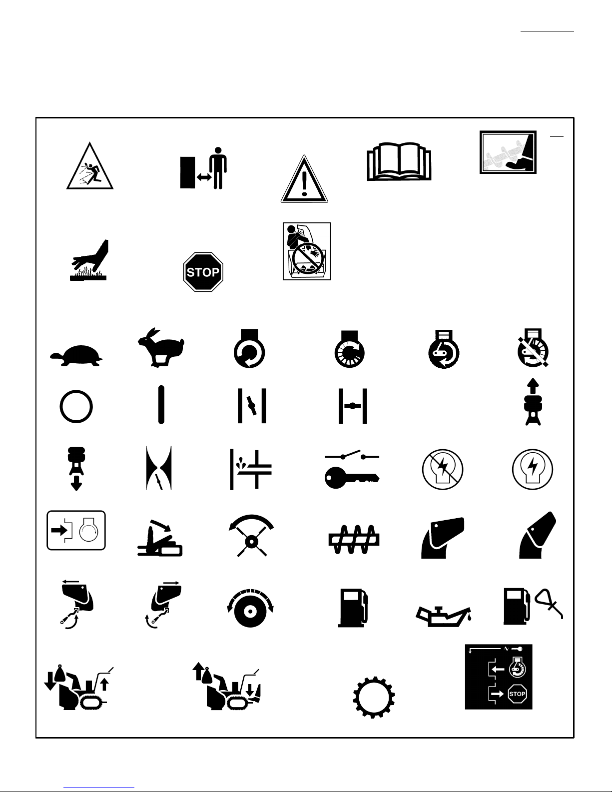
INTERNATIONAL PICTORIALS
IMPORTANT: The following pictorials are located on your unit or on literature supplied
with the product. Before you operate the
unit, learn and understand the purpose for
each pictorial.
18
Engine Off
Engine Stop On Choke Off Choke On
Neutral
N
Slow Fast Electric Start Engine Start Engine Run
Throttle Primer Button Ignition Key Ignition Off Ignition On
Drive Clutch
Forward
Auger Clutch
Auger Collector
Reverse
Engage
Ignition Key
Insert To Run, Pull Out To Stop.
Fuel Oil Fuel Oil Mixture
Discharge DOWN Discharge UP
Discharge LEFT Discharge RIGHT
KGS
KGS
Weight Transfer
Lift Handle To Engage
Weight Transfer
Depress Pedal To Disengage
Transmission
Push To Engage
Electric Starter
Control And Operating Symbols
Safety Warning Symbols
DANGER
Thrown Objects.
Keep Bystanders Away.
DANGER
Thrown Objects.
Keep Bystanders Away.
WARNING
IMPORTANT
Read Owner’s Manual
Before Operating
This Machine.
DANGER
Avoid Injury From
Rotating Auger. Keep
Hands, Feet And
Clothing Away.
DANGER
Stop The Engine Before
Unclogging Discharge
Chute!
STOP
WARNING
Hot Surface
Page 8

ENGLISH
8
F-041016C
Safe Operation Practices for Snow Throwers
As Recommended By: American National Standards Institute.
IMPORTANT: Safety standards require operator
presence controls to minimize the risk of injury.
Your snow thrower is equipped with such controls. Do not attempt to defeat the function of the
operator presence control under any circumstances.
Training
1. Read the operating and service instruction
manual carefully. Be thoroughly familiar with
the controls and the proper use of the equipment. Know how to stop the unit and disengage the controls quickly.
2. Never allow children to operate the equipment. Never allow adults to operate the
equipment without proper instruction.
3. Keep the area of operation clear of all persons, particularly small children and pets.
4. Exercise caution to avoid slipping or falling
especially when operating in reverse.
Preparation
1. Thoroughly inspect the area where the equipment is to be used and remove all doormats,
sleds, boards, wires, and other foreign objects.
2. Disengage all clutches before starting the engine (motor).
3. Do not operate the equipment without wearing adequate winter outer garments. Wear
footwear that will improve footing on slippery
surfaces.
4. Handle fuel with care; it is highly flammable.
a. Use an approved fuel container.
b. Never remove fuel tank cap or add fuel to
a running engine (motor) or hot engine
(motor).
c. Fill fuel tank outdoors with extreme care.
Never fill fuel tank indoors.
d. Replace fuel cap securely and wipe up
spilled fuel.
e. Never store fuel or snow thrower with fuel
in the tank inside of a building where
fumes may reach an open flame or spark.
f. Check fuel supply before each use, allow-
ing space for expansion as the heat of the
engine (motor) and/or sun can cause fuel
to expand.
5. For all units with electric starting motors use
electric starting extension cords certified
CSA/UL. Use only with a receptacle that has
been installed in accordance with local inspection authorities.
6. Adjust the snow thrower height to clear gravel
or crushed rock surface.
7. Never attempt to make any adjustments
while the engine (motor) is running (except
when specifically recommended by manufacturer).
8. Let engine (motor) and snow thrower adjust
to outdoor temperatures before starting to
clear snow.
9. Always wear safety glasses or eye shields
during operation or while performing an adjustment or repair to protect eyes from foreign
objects that may be thrown from the snow
thrower.
Operation
1. Do not operate this machine if you are taking
drugs or other medication which can cause
drowsiness or affect your ability to operate
this machine.
2. Do not use this machine if you are mentally
or physically unable to operate this machine
safely.
3. Do not put hands or feet near or under rotating parts. Keep clear of the discharge opening at all times.
4. Exercise extreme caution when operating on
or crossing gravel drives, walks or roads.
Stay alert for hidden hazards or traffic.
5. After striking a foreign object, stop the engine
(motor), remove the wire from the spark plug,
thoroughly inspect snow thrower for any
damage, and repair the damage before restarting and operating the snow thrower.
6. If the unit should start to vibrate abnormally,
stop the engine (motor) and check immediately for the cause. Vibration is generally a
warning of trouble.
7. Stop the engine (motor) whenever you leave
the operating position, before unclogging the
auger/impeller housing or discharge chute
and when making any repairs, adjustments,
or inspections.
8. When cleaning, repairing, or inspecting, make
certain the auger/impeller and all moving
parts have stopped and all controls are disengaged. Disconnect the spark plug wire and
keep the wire away from the spark plug to
prevent accidental starting.
9. Take all possible precautions when leaving
the snow thrower unattended. Disengage the
auger/ impeller, stop engine (motor), and remove key.
10. Do not run the engine (motor) indoors, except
when starting the engine (motor) and for
transporting the snow thrower in or out of the
building. Open the outside doors; exhaust
fumes are dangerous (containing CARBON
MONOXIDE, an ODORLESS and DEADLY
GAS).
11. Do not clear snow across the face of slopes.
Exercise extreme caution when changing
direction on slopes. Do not attempt to clear
steep slopes.
12. Never operate the snow thrower without
proper guards, plates or other safety protective devices in place.
13. Never operate the snow thrower near enclosures, automobiles, window wells, drop- offs,
and the like without proper adjustment of the
snow discharge angle. Keep children and
pets away.
14. Do not overload the machine capacity by attempting to clear snow at too fast a rate.
15. Never operate the machine at high transport
speeds on slippery surfaces. Look behind
and use care when backing up.
16. Never direct discharge at bystanders or allow
anyone in front of the unit.
17. Disengage power to the collector/impeller
when snow thrower is transported or not in
use.
18. Use only attachments and accessories approved by the manufacturer of the snow
thrower (such as tire chains, electric start kits,
ect.).
19. Never operate the snow thrower without good
visibility or light. Always be sure of your footing and keep a firm hold on the handles.
Walk;never run.
20. Do not over- reach. Keep proper footing and
balance at all times.
21. Exercise caution if operating on steep sloping surfaces.
22. This snow thrower is for use on sidewalks,
driveways and other ground level surfaces.
23. Do not use the snow thrower on surfaces
above ground level such as roofs of residences, garages, porches or other such
structures or buildings.
Maintenance And Storage
1. Check shear bolts and other bolts at frequent
intervals for proper tightness to be sure the
equipment is in safe working condition.
2. Never store the snow thrower with fuel in the
tank inside a building where ignition sources
are present such as hot water and space
heaters, clothes dryers, and the like. Allow
the engine (motor) to cool before storing in
any enclosure.
3. Always refer to operator’s guide instructions
for important details if the snow thrower is to
be stored for an extended period.
4. Maintain or replace safety and instruction labels, as necessary.
5. Run the snow thrower a few minutes after
throwing snow to prevent freeze- up of the
auger/impeller.
Page 9
ENGLISH
9
F-041016C
ASSEMBLY
Read and follow the assembly and adjustment
instructions for your snow thrower. All fasteners
are in the parts bag. Do not discard any parts or
material until the unit is assembled.
WARNING: Before doing any
assembly or maintenance to the
snow thrower, remove the wire
from the spark plug.
NOTE: In this instruction book, left and right
describe the location of a part from the operator’s position behind the unit.
NOTE: Torque is measured in foot pounds
(metric N.m). This measurement describes
how tight a nut or bolt must be. The torque is
measured with a torque wrench.
NOTE: Illustrations begin on page 3.
Tools Required
1 Knife
1 Pliers
How To Remove The Snow Thrower
From The Carton
1. Locate all parts that are packed separately
and remove from the carton.
2. Remove and discard the packing material
from around the snow thrower.
3. Cut down all four corners of the carton and
lay the side panels flat.
4. Hold onto the lower handle and pull the snow
thrower off the carton.
CAUTION: DO NOT back over cables.
5. Remove the packing material from the handle assembly.
How To Assemble The Handle
1. Remove the packing material from the upper
and lower handles.
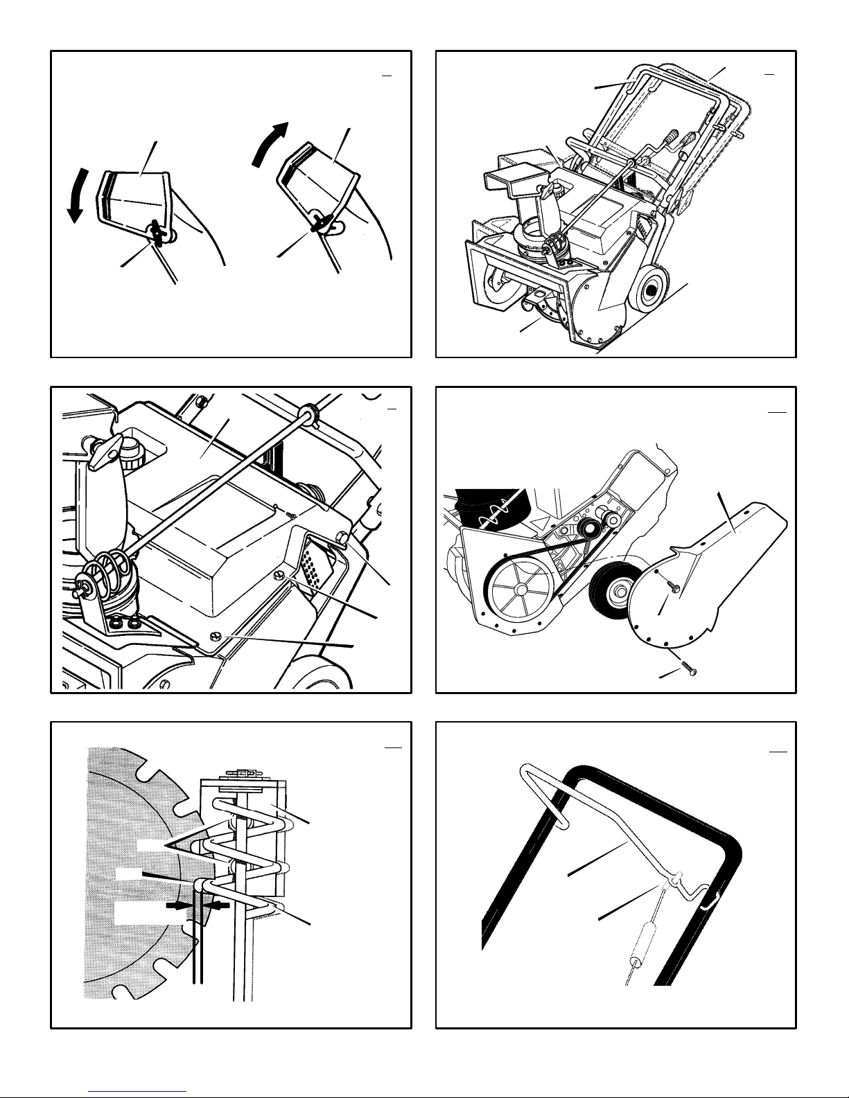
2. (Figure 1) Loosen the knobs (1) on each
side of the handle (2).
3. Raise the upper handle (2) to the operating
position.. Hold the upper handle (2) apart to
prevent scratching the lower handle.
NOTE: Make sure the cables are not
caught between the upper and lower handle.
4. Tighten the knobs (1).
5. (Figure 2) Cut and discard the cable tie (3)
from the lower end of the chute control rod
(4).
6. Turn the chute deflector (5) around toward
the front of the snow thrower.
How To Assemble The Lower Chute
(Figure 3)
For shipping purposes, some models are
shipped with the rear nut and bolt removed from
the lower chute (3). If the lower chute is not attached, assemble as follows.
1. Use the bolt (1) and nut (2) found in the
parts bag to attach the lower chute (3).
2. Tip the lower chute (3) backward until the
hole in the chute ring is aligned with the hole
in the lower chute (3).
3. Attach the lower chute (3) with bolt (1) and
nut (2). Make sure the nut (2) is tight.
How To Assemble
The Chute Control Rod (Figure 4)
1. Remove the cotter pin (1), flat washer (2),
and wave washer (3) from the end of the
chute control rod (4). DO NOT DISCARD.
2. Mount the end of the chute control rod (4)
through the hole in the control rod bracket
(5). Make sure the worm gear (6) is aligned
with the notches (7) in the discharge chute
(8).
3. Fasten the chute control rod (4) to the con-
trol rod bracket (5) with cotter pin (1), flat
washer (2), and wave washer (3).
4. Rotate the chute control rod (4) clockwise
and counterclockwise. Make sure the dis-
charge chute (8) rotates freely.
How To Prepare The Engine
WARNING: Follow the engine
manufacturer’s instructions for the
type of fuel and oil to use. Always
use a safety fuel container. Do not smoke
when adding the fuel mixture to the engine.
When inside an enclosure, do not fill the
fuel tank. Before you add the fuel mixture,
stop the engine. Let the engine cool for
several minutes.
See the engine manufacturer’s instructions for
the type of fuel and oil to use. Before you use
the unit, read the information on safety, operation, maintenance, and storage.
NOTE: Engine horsepower ratings may vary
by engine adjustments, manufacturing variances, altitude, atmospheric conditions, fuel
and maintenance.
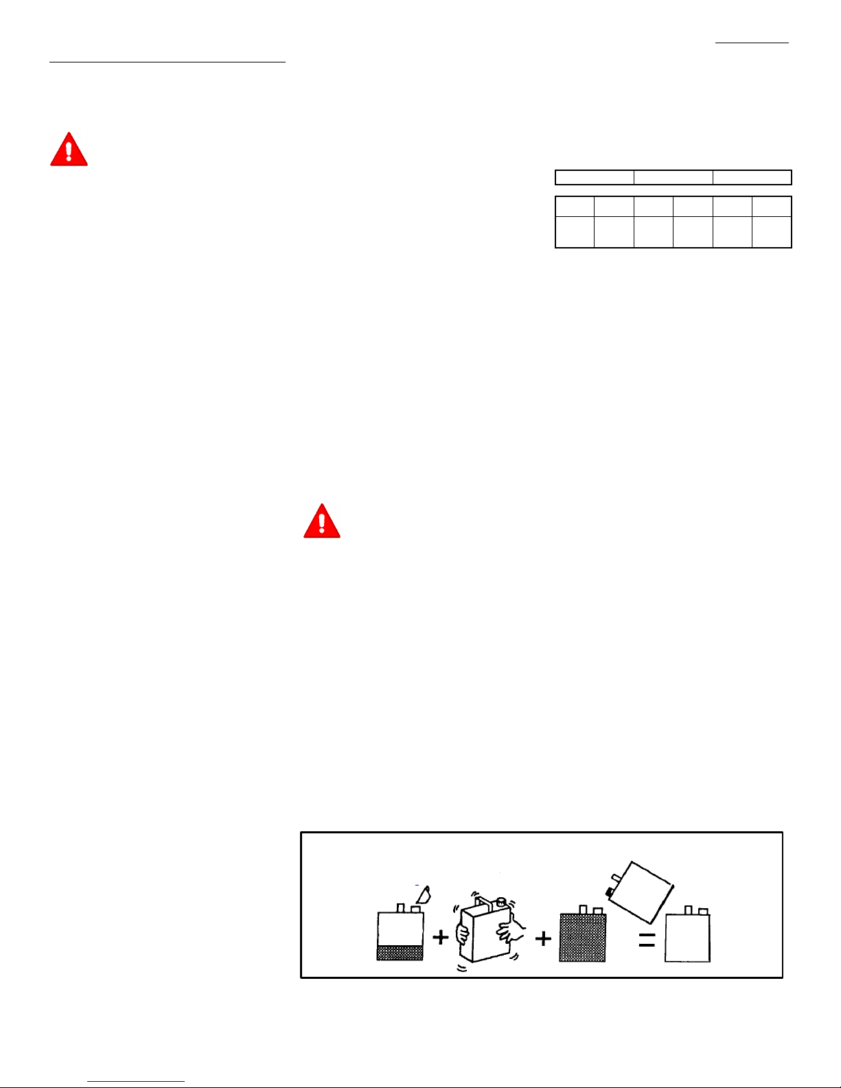
How To Mix The Fuel Mixture
The two cycle engine, used on this snow thrower, requires a mixture of gasoline and oil for lu-
brication of the bearings and other moving parts.
The correct fuel mixture ratio is 50:1 (2.6 oz. oil
per one gallon of gas - see the Fuel Mixture
Chart). Gasoline and oil must be pre-mixed in a
clean gasoline container. Always use fresh,
clean, unleaded gasoline.
FUEL MIXTURE CHART (mixture 50:1)
U.S. IMPERIAL SI. (Metric
GAS OIL GAS OIL GAS OIL
1
Gal.
2.6
oz1Gal.
3.1oz1
liter20ML
Mix gasoline and oil as follows:
1. Pour one (1) U.S. quart of fresh, clean, unleaded automotive gasoline into a one gallon
size gasoline container.
2. Add 2.6 ounces of clean, high quality, twocycle oil to the gasoline container.
IMPORTANT: Do not use outboard motor
oil or multi-viscosity oils,such as 10W-30
or 10W-40.
3. Install the fuel cap onto the gasoline container. Vigorously shake the gasoline container
to mix the oil with the gasoline.
4. Add an additional three (3) U.S. quarts of
gasoline to the gallon container. Again shake
the gasoline container.
Before You Operate
Before you operate your new snow thrower,
please review the following checklist:
G Make sure all assembly instructions have
been completed.
G Make sure the discharge chute rotates freely.
G Make sure that no loose parts remain in the
carton.
As you learn how to properly use the snow
thrower, pay extra attention to the following important items.
G Make sure the fuel tank is filled with the
correct mixture of gasoline and oil.
G Become familiar with the location of all
controls and understand their function.
G Before starting the engine, make sure all
controls operate correctly.
Do not fill the fuel tank with gasoline that does not have oil mixed in it. Shake the
gasoline container before each filling of the fuel tank.
Shake Can
OIl
(2.6 oz)
Gasoline
1U.S.
Quart
1 U.S. Gallon container
1 U.S.
Gallon
Special
Gasoline
Add more gas
(3 U. S. Quarts)
Page 10
ENGLISH
10
F-041016C
OPERATION
NOTE: Illustrations begin on page 3.
Know Your Snow Thrower (Figure 6)
Read this Instruction Book and safety rules before operation the snow thrower. Compare the
illustration with your snow thrower to familiarize
yourself with the location of various controls and
adjustments.
Crank Assembly (2) - Changes the direction of
the discharge chute.
Chute Deflector (3) - Changes the distance the
snow is thrown.
Discharge Chute (4) - Changes the direction the
snow is thrown.
Auger Drive Lever (5) - Starts and stops the auger which propels the snow thrower.
Ignition Key (8) - Must be inserted and turned to
the on position to start the engine.
Primer Button (9) - Injects fuel directly into the
carburetor for fast starts in cold weather.
Electric Start Button (10) - On electric start models, used to start the engine.
Switch Box (11) - On electric start models, used
to attach a 120 volt electric power cord.
Recoil Starter Handle (12) - Use to manually
start the engine.
Choke Control (14) - Use to start a cold engine.
Spark Plug Access Panel (15) - Remove to ac-
cess the spark plug.
How To Control
The Discharge Of The Snow
WARNING: Never direct the discharge of snow toward bystanders.
WARNING: Always stop the engine
before unclogging the discharge
chute or the auger housing and be-
fore leaving the snow thrower.
1. (Figure 6) Turn the crank assembly (2) to
change the discharge direction of the snow.
2. (Figure 7) Loosen the wing knob (1) on the
chute deflector (2).
3. Move the chute deflector (2) up for more
distance or down for less distance.
4. Tighten the wing knob (1).
How To Throw Snow (Figure 6)
1. Engage the auger drive lever (5).
2. To stop throwing snow, release the auger
drive lever (5).
WARNING: The operation of any
snow thrower can result in foreign
objects being thrown into the eyes,
which can result in severe eye damage.
Always wear safety glasses or eye shields
while operating the snow thrower. We recommend standard safety glasses or use a
wide vision safety mask over your glasses.
How To Stop Discharging Snow
(Figure 6)
1. To stop discharging snow, release the auger
drive lever (5).
2. To stop the engine, turn the ignition key (8)
to the off position.
How To Move Forward (Figure 8)
1. Hold the auger drive lever (5) against the
handle (2). The auger will begin rotating.
2. To go forward, raise the handle (2) to allow
the rubber auger blades (1) to contact the
ground. Maintain a firm hold on the handle
(2) as the snow thrower starts to move forward. Guide the snow thrower by moving the
handle (2) either left or right. Do not attempt
to push the snow thrower.
3. To stop, release the auger drive lever (5).
NOTE: If the auger continues to rotate, see
“How To Adjust The Auger Control Cable” in
the Service and Adjustments section.
Before Starting The Engine
1. Before you service or start the engine, familiarize yourself with the snow thrower. Be
sure you understand the function and location of all controls.
2. Make sure that all fasteners are tight.
3. Make sure the fuel tank is filled with the correct mixture of gasoline and oil.
4. Become familiar with the location of all controls and understand their function.
5. Before starting the engine, make sure all
controls operate corrently.
Add The Fuel Mixture
WARNING: Follow the engine
manufacturer’s instructions for the
type of fuel and oil to use. Always
use a safety fuel container. Do not smoke
when adding the fuel mixture to the engine.
When inside an enclosure, do not fill the
fuel tank. Before you add the fuel mixture,
stop the engine. Let the engine cool for
several minutes.
(Figure 8) Fill the fuel tank (3) to the full posi-
tion with a fresh, clean fuel mixture. See “How
To Mix The Fuel Mixture” in the Assembly section.
How To Stop The Engine (Figure 6)
To stop the engine, turn the ignition key (8) to
the off position. Keep the ignition key (8) in a
safe place. The engine will not start without the
ignition key (8).
How To Start The Engine (Figure 6)
Models equipped with an Electric Starter
NOTE: An electric starter kit can be added to
recoil start engines. Electric starter kits are
available from your nearest authorized service center.
WARNING: The starter is equipped
with a three- wire power cord and
plug and is designed to operate on
120 volt A.C. household current. The power
cord must be properly grounded at all times
to avoid the possibility of electrical shock
which can injure the operator. Carefully follow all instructions in the “How To Start The
Engine” section. Make sure that your house
wiring is a three- wire grounded system. If
you are not sure, ask a licensed electrician.
If your house wire system is not a
three- wire grounded system, do not use
this electric starter under any conditions. If
your system is grounded but a three- hole
grounded receptacle is not available to start
the engine, have a three- hole grounded receptacle installed by a licensed electrician.
To connect a 120 volt A.C. power cord, always connect the power cord to the switch
box (11) on the engine first. Then, plug the
other end into the three- hole grounded receptacle. When disconnecting the power
cord, always unplug the end from the
three- hole grounded receptacle first.
How To Start A Cold Engine (Figure 6)
1. Fill the fuel tank with a fresh, clean fuel misture. See “How To Mix The Fuel Mixture” in
the Assembly section.
2. Move the choke control to FULL position.
3. Make sure the auger drive lever (5) is in the
disengaged (released) position.
4. Insert the ignition key (8) and turn to the on
position.
5. Move the choke control (14) to the full
choke position.
6. (Electric Start) Connect the power cord to
the switch box (11) located on the engine.
7. (Electric Start) Plug the other end of the
power cord into a three-hole, grounded 120
VOLT, A.C. receptacle. (See the WARNING
in this section).
8. Push the primer button (9). Every time you
push the primer button (9), wait two seconds. For the number of times required to
push the primer button (9), see the engine
manufacturer’s instructions.
9. (Electric Start) Push on the electric start
button (10) until the engine starts. Do not
crank for more than 10 seconds at a time.
The electric starter is thermally protected. If
the electric starter overheates, it will automatically stop and can only be restarted
when it has cooled to a safe temperature. A
wait of about 5 to 10 minutes is required to
allow the electric starter to cool.
10.(Recoil Start) Rapidly pull the recoil starter
handle (12). Do not allow the recoil starter
handle (12) to snap back. Slowly return the
recoil starter handle (12).
11.If the engine does not start in 5 or 6 tries,
See the “Trouble Shooting Chart” Instructions.
12.(Electric Start) When the engine starts, release the electric start button (10) and
move the choke control (14) to 1/2 choke
position. When the engine runs smoothly,
move the choke control (14) to the off position.
Page 11

ENGLISH
11
F-041016C
13.(Electric Start) First disconnect the power
cord from the three-hole receptacle. Then,
disconnect the power cord from the switch
box (11).
NOTE: In temperatures below 05F, allow
the engine to warm up for several minutes
before blowing snow.
WARNING: Never run the engine
indoors or in enclosed, poorly ven-
tilated areas. Engine exhaust contains carbon monoxide, an odorless and
deadly gas. Keep hands, feet, hair and
loose clothing away from any moving parts
located on the engine or the snow thrower.
The temperature of muffler and nearby
areas may exceed 150°F. Avoid these
areas.
How To Start A Warm Engine (Figure 6)
If an engine has been running and is still warm,
leave the choke control (14) in the off position
and do not push the primer button (9). If the
engine fails to start, follow the instructions “How
To Start A Cold Engine”.
NOTE: Do not use the primer button (9) to
start a warm engine.
How To Start An Engine With A Frozen Electric
Starter (Figure 6)
If the electric starter is frozen and will not turn
the engine, follow the instructions below.
1. Pull out the recoil starter handle (12) as far
as possible.
2. Quickly release the recoil starter handle
(12). Allow the recoil starter handle (12) to
snap back against the recoil starter.
If the engine still fails to start, repeat the two previous steps until the engine starts. Then, continue with the directions “How To Start A Cold
Engine”.
To help prevent the possible freeze-up of the
recoil starter and of the engine controls, proceed
as follows after each snow removal job.
1. With the engine running, quickly pull the re-
coil starter handle (12) three or four times
with a continuous full arm stroke. This will
produce a loud clattering sound that is not
harmful to the engine or starter.
2. Stop the engine. Wipe all snow and moisture
from the carburetor cover, control levers and
cables. Also move the choke control (14)
and recoil starter handle (12) several times.
How To Remove Snow or Debris From
The Auger Housing
(Figure 6)
WARNING: Do not attempt to remove snow or debris that may become lodged in auger housing
without taking the following precautions.
1. Release the auger drive lever (5).
2. Remove the ignition key (8).
3. Disconnect the spark plug wire.
4. Do not place your hands in the auger hous-
ing (4) or the discharge chute (3). Use a
pry bar to remove any snow or debris.
Snow Throwing Tips
1. This snow thrower will propel itself forward
when the handle is raised enough to cause
the auger blades to contact the ground. The
auger should stop when auger control bar is
released. If it does not stop, see “How To Adjust The Auger Control Cable” in the adjustment section.
2. Most efficient snow throwing is accomplished
when the snow is removed immediately after
if falls.
3. For complete snow removal, slightly overlap
each previous path.
4. Whenever possible, discharge the snow
down wind.
5. The distance the snow will be discharged
can be adjusted by moving the discharge
chute deflector. Raise the deflector for more
distance or lower the deflector for less distance.
6. In windy conditions, lower the chute deflector
to direct the discharged snow close to the
ground where it is less likely to blow into unwanted areas.
7. For safety and to prevent damage to the
snow thrower, keep the area to be cleared
free of stones, toys and other foreign objects.
8. Do not use the auger propelling feature when
clearing gravel or crushed rock driveways.
Move the handle down to slightly raise the
auger.
9. The forward speed of the snow thrower is
dependent on the depth and weight of the
snow. Experience will establish the most effective method of using the snow thrower under different conditions.
10.After each snow throwing job, allow the engine to run for a few minutes. The snow and
accumulated ice will melt off the engine.
11.Clean the snow thrower after each use.
12.Remove ice, snow and debris from the entire
snow thrower. Flush with water to remove all
salt or other chemicals. Wipe snow thrower
dry.
Dry And Average Snow
1. Snow up to eight inches deep can be removed rapidly and easily by walking at a
moderate rate. For snow or drifts of a greater
depth,slow your pace to allow the discharge
chute to dispose of the snow as rapidly as
the auger receives the snow.
2. Plan to have the snow discharged in the direction the wind is blowing.
Wet Packed Snow
Move slowly into wet, packed snow. If the wet,
packed snow causes the auger to slow down or
the discharge chute begins to clog, back off and
begin a series of short back and forth jabs into
the snow. These short back and forth jabs, four
to six inches, will “belch” the snow from the
chute.
Snow Banks And Drifts
In snow of greater depth than the unit, use the
same “jabbing” technique described above. Turn
the discharge chute away from the snow bank.
More time will be required to remove snow of
this type than level snow.
Page 12

ENGLISH
12
F-041016C
MAINTENANCE CHART
CUSTOMER RESPONSIBILITIES
SERVICE RECORDS
Fill in dates as you
complete regular
service.
Before
Each
Use
First
2
Hours
Every
5
Hours
Every
10
Hours
Every
25
Hours
Each
Season
Before
Storage
SERVICE DATES
Check And Tighten All Screws and Nuts
√ √
Check Spark Plug
√ √
Check Drive Belt
√
Check Fuel
√
Drain Fuel
√
Lubricate Chute Control Flange
√
MAINTENANCE
NOTE: Illustrations begin on page 3.
Use the following maintenance section to keep
your unit in good operating condition. All the
maintenance information for the engine is in the
engine manufacturer’s instructions. Before you
start the engine, read this book.
WARNING: Before you make an inspection, adjustment (except
carburettor), or repair, disconnect
the wire from the spark plug.
General Recommendations
The warranty on this snow thrower does not cover items that have been subjected to operator
abuse or negligence. To receive full value from
the warranty, the operator must maintain the
snow thrower as instructed in this manual.
Some adjustments must be made periodically to
properly maintain the snow thrower.
After Each Use
G Check for any loose or damaged parts.
G Tighten any loose fasteners.
G Check and maintain the auger.
G Check controls to make sure they are
functioning properly.
G If any parts are worn or damaged, replace
immediately.
All adjustments in the Maintenance section of
this manual should be checked at least once
each season.
How To Remove The Top Cover
(Figure 9)
1. Remove the five screws (1) from the top
cover (2).
2. Remove the top cover (2).
3. To install the top cover (4), reverse the
above steps.
Lubrication
Before Storage (Figure 9)
1. Lubricate the clute control flange (7). Apply
a clinging type of grease such as Lubriplate.
How To Adjust The Chute Crank
If the chute crank will not rotate fully to the left or
right, adjust as follows.
1. (Figure 11) Loosen nuts (1).
2. Move the crank adjusting bracket (2) to
allow 1/8 inch (3mm) clearance (3) between
the notch in the flange (4) and the outer diameter of the worm gear (5).
3. Tighten the nuts (1).
How To Adjust The Auger Control Cable
The auger control cable is adjusted at the factory. During normal use, the auger control cable
can become stretched and the auger drive lever
will not properly engage or disengage the auger.
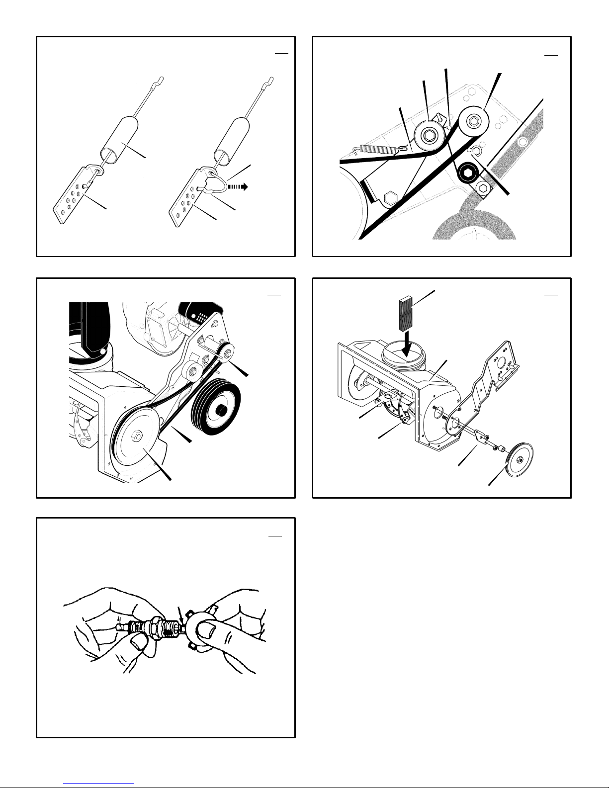
1. (Figure 12) Remove the “Z” hook (1) from
the auger drive lever (2).
2. (Figure 13) Slide the cable boot (3) off the
cable adjustment bracket (4).
3. Push the bottom of the auger control cable
(5) through the cable adjustment bracket
(4) until the “Z” hook (6) can be removed.
4. Remove the “Z” hook (6) from the cable
adjustment bracket (4). Move the “Z” hook
(6) down to the next adjustment hole.
5. Pull the auger control cable (5) up through
the cable adjustment bracket (4).
6. Put the cable boot (3) over the cable ad-
justment bracket (4).
7. (Figure 12) Install the “Z” hook (1) to the
auger drive lever (2).
8. To check the adjustment, start the snow
thrower. Make sure the auger does not rotate
when the auger drive lever is released.
How To Remove The Belt Cover
(Figure 10)
1. The belt cover (1) is fastened with ten
screws (2). Remove all ten screws.
2. There are five screws on the front of the belt
cover (1). Three screws on the bottom of the
belt cover (1). Two screws on the top of the
belt cover (1).
3. Remove the belt cover (1).
4. To install the belt cover (1), reverse the
above steps.
NOTE: One screw (3) is shorter than the other screws. Make sure to install screw (3) in
the correct location.
How To Replace The Drive Belt
The drive belt is of special construction and
must be replaced with original factory replacement belt available from your nearest authorized
service center.
1. Remove the belt cover. See “How To Remove The Belt Cover”.
2. (Figure 14) Remove the drive belt (1) from
the idler pulley (2).
3. Remove the drive belt (1) from the engine
pulley (3). Be careful, not to bend the belt
guides (4).
4. (Figure 15) Remove the drive belt (1) from
the auger pulley (5).
5. Remove the old drive belt (1).
6. To install the new drive belt (1), reverse the
above steps.
7. Make sure the drive belt (1) is seated prop-
erly on the pulleys.
NOTE: When the auger control lever is
engaged, the belt guides (4) must be 1/16”
from the drive belt (1).
8. Install belt cover. See “How To Remove The
Belt Cover”.
How To Replace The Auger (Figure 16)
1. Remove the belt cover. See “How To Remove The Belt Cover”.
2. Remove the drive belt. See “How To Replace
The Drive Belt”.
3. Remove the auger pulley (1) from the auger
shaft (threads are left hand; turn clockwise to
remove).
4. To keep the auger (6) from rotating, set a
2”x4” piece of wood (2) on the center
paddle (3) to secure auger (6).
5. Remove the fasteners from the bearing as-
sembly (4). Remove the bearing assembly
(4) from the auger housing (5).
6. Slide the auger (6) out of the bearing assem-
bly on the right side of the snow thrower.
7. Tip the auger (6) enough to allow the auger
(6) to slide out of the auger housing (5).
8. To install auger (6), reverse the above steps.
Page 13
ENGLISH
13
F-041016C
How To Replace The Spark Plug
NOTE: This spark ignition system meets all
requirements of the Canadian InterferenceCausing Equipment Regulations.
NOTE: This engine complies with all current
Australian and New Zealand limitations electromagnetic interference.
The spark plug is housed in the engine compartment under the top cover and cannot be seen
under normal conditions.
1. Remove the top cover. See “How To Remove
The Top Cover”.
2. The spark plug and wire are now visible.
3. Remove the spark plug wire.
4. Clean the area around the spark plug base to
prevent dirt from entering the engine when the
spark plug is removed.
5. Remove the spark plug.
6. Check the spark plug. If the spark plug is
cracked, fouled or dirty, it must be replaced .
7. (Figure 17) Set the gap between the electrodes of the new spark plug at .030 inch. Next,
install the spark plug in the cylinder head and
firmly tighten. Recommended torque is 18 to
20 foot pounds.
How To Prepare The Snow Thrower For
Storage
WARNING: Do not remove gasoline
while inside a building, near a fire,
or while you smoke. Gasoline
fumes can cause an explosion or a fire.
1. Drain the fuel tank.
2. Let the engine run until it is out of gasoline.
3. Remove the spark plug from the cylinder.
Pour one ounce of oil into the cylinder. Slowly pull the recoil-start grip so that the oil will
protect the cylinder. Install a new spark plug
in the cylinder.
4. Thoroughly clean the snow thrower.
5. Lubricate all lubrication points. See the Maintenance section.
6. Be sure that all nuts, bolts and screws are
securely fastened. Inspect all visible moving
parts for damage, breakage and wear. Replace if necessary.
7. Cover the bare metal parts of the blower
housing and auger with spray rust preventative lubricant.
8. Put the unit in a building that has good ventilation.
9. If the machine must be stored outdoors,
block up the snow thrower to be sure the entire machine is off the ground.
10.Cover the snow thrower with a suitable protective cover that does not retain moisture.
Do not use plastic.
How To Order Replacement Parts
The replacement parts are shown either on the
back pages of this Instruction Book or in a
separate Parts List Book.
Use only manufacturer’s authorized or approved
replacement parts. The letter placed on the end
of the part number denotes the type of finish for
the part, C for chrome, Z for zinc, a PA for
purchased assembly. It is important that you
include this when ordering a part. Do not use
attachments or accessories not specifically
recommended for this unit. In order to obtain
proper replacement parts you must supply the
model number (see nameplate).
Replacement parts, except for the engine,
transmission, transaxle or differential, are
available from the store where the product was
purchased, a service shop recommended by the
store or from a “Murray, Inc. Central Parts
Distributor” listed on the back page of this
Instruction Book.
If you are unable to obtain parts or service in the
manner outlined above, then contact:
USA - MURRAY, INC.
Outdoor Power Equipment
Customer Service Department
P.O. Box 268
Brentwood, Tennessee 37027
1-800-251-8007
CANADA - MURRAY CANADA, INC.
Factory Customer Service
1195 Coutneypark Drive East
Mississauga, Ont. L5T-1R1
1-800-661-6662 Collect telephone calls will not
be accepted.
Replacement parts for the engine, transaxle, or
transmission, are available from the
manufacturer’s authorized service center found
in the yellow pages of the telephone directory.
Also, see the individual engine or transmission
warranties to order replacement parts.
When ordering the following information is
required:
(1) The Model Number
(2) Serial Number
(3) Part Number
(4) Quantity
Page 14

ENGLISH
14
F-041016C
TROUBLE SHOOTING CHART
TROUBLE CAUSE CORRECTION
Difficult starting Defective spark plug. Replace spark plug.
Water or dirt in fuel system. Use carburetor bowl drain to flush and refill with
fresh fuel.
Engine runs erratic Blocked fuel line, empty gas tank, or stale
gasoline
Clean fuel line; check fuel supply; add fresh
gasoline
Engine stalls Unit running on CHOKE. Set choke lever to RUN position.
Engine runs erratic;
Loss of power
Water or dirt in fuel system. Use carburetor bowl drain to flush and refill with
fresh fuel.
Excessive vibration Loose parts: damaged impeller Stop engine immediately and disconnect spark
plug wire. Tighten all bolts and make all
necessary repairs. If vibration continues, have
the unit serviced by a competent repairman.
Unit fails to propel itself Drive belt loose or damaged. Replace drive belt.
Unit fails to discharge snow Auger drive belt loose or damaged. Adjust auger drive belt; replace if damaged.
Auger control cable not adjusted correctly. Adjust auger control cable.
Discharge chute clogged. Stop engine immediately and disconnect spark
plug wire. Clean discharge chute and inside of
auger housing.
Foreign object lodged in auger Stop engine immediately and disconnect spark
plug wire. Remove object from auger.
Page 15

FRANÇAIS
15
F-041016C
SOMMAIRE
INFORMATIONS SUR LE PRODUIT 15
INFORMATIONS DESTINEES AU
PROPRIETAIRE 15
PICTOGRAMMES INTERNATIONAUX 16
MONTAGE 18
FONCTIONNEMENT 19
MAINTENANCE 21
TABLEAU DE MAINTENANCE 21
TABLEAU DE DEPANNAGE 23
GARANTIE LIMITEE DE DEUX ANS
Murray, Inc. garantie auprès de l’acheteur initial
que cette machine est dépourvue de défauts
matériels et de construction sous utilisation et
entretien normaux pendant une durée de deux
(2) ans à partir de la date d’acquisition ; cette
garantie cependant ne couvre pas les moteurs,
accessoires (tels que moteurs électriques) et
pièces d’usure normale (exceptées les pièces
mentionnées ci-dessous) étant donné que les
sociétés fabriquant ces articles offrent leurs
propres garanties et fournissent des réparations
par le biais de leurs centres de maintenance
spécialisés agréés. Pour plus d’informations, se
reporter aux garanties couvrant ces pièces
particulières. Si vous ne savez pas si votre
machine contient ou est équipée d’une ou
plusieurs de ces pièces, adressez vous à votre
revendeur avant l’acquisition. Sous réserve des
modalités et conditions de cette garantie limitée,
nous nous engageons à réparer ou remplacer, à
notre discrétion et gratuitement auprès de
l’acheteur initial, toute pièce couverte par cette
garantie limitée jusqu’à l’expiration de la garantie
applicable.
Les pièces d’usure normale comprennent les
courroies d’entraînement, les fraises
hélicoïdales, les goupilles de cisaillement, les
pneumatiques, et les phares. Ces pièces sont
garanties sans défaut matériel ou de
construction dans l’état où elles ont été livrées
avec le produit. Toute réclamation concernant la
réparation ou le remplacement d’une pièce
d’usure normale doit être effectuée dans les
trente (30) jours suivant la date d’acquisition.
Aucune réclamation ne sera honorée
concernant des dommages provenant de la
simple utilisation, d’un usage abusif, ou d’une
mauvaise utilisation.
Cette garantie Murray, Inc. de deux (2) ans
constitue votre recours exclusif ; cependant,
cette garantie est nulle ou ne s’applique pas aux
machines ayant été modifiées, endommagées,
fait l’objet d’une utilisation abusive, ou utilisées
lors d’une location ou à des fins commerciales
et/ ou professionnelles (autre que domestiques).
Votre garantie ne couvre pas les réglages
mécaniques mineurs non dus à des défauts
matériels de fabrication. Consultez votre manuel
d’utilisation pour obtenir une assistance
concernant ces réglages.
Pour effectuer une réclamation sous la garantie
limitée de deux (2) ans Murray, Inc., retourner
la machine, (ou, suivant notre autorisation
préalable, la pièce défectueuse) accompagnée
de votre preuve d’achat, auprès du Centre de
maintenance agréé le plus proche de chez vous.
Pour localiser le centre de maintenance le plus
proche, contactez le Distributeur de pièces
régional de votre région figurant sur la liste
fournie avec votre machine, ou consultez les
pages jaunes de votre annuaire téléphonique
local. Si vous nous retournez la machine
complète, nous réparerons celle-ci. Si nous
autorisons seulement le retour de la pièce
défectueuse, nous effectuerons soit la réparation
de celle-ci, soit son remplacement. Cette
garantie limitée Murray, Inc. de deux (2) ans
vous octroie des droits légaux spécifiques, et
vous pouvez également vous prévaloir d’autres
droits dont le contenu varie selon l’Etat où ils
s’appliquent. Cette garantie limitée est
délivrée en lieu et place de toute garantie
stipulée ou tacite, ceci incluant la garantie
tacite de commerciabilité et la garantie de
fonctionnalité pour une tâche définie. Si
vous souhaitez recevoir des informations
supplémentaires concernant cette garantie
écrite ou une assistance quant à l’obtention de
services de réparation, adressez-vous à :
USA - MURRAY, INC.
Outdoor Power Equipment
Customer Service Department
P.O. Box 268
Brentwood, Tennessee 37027
1-800-251-8007
CANADA - MURRAY CANADA, INC.
Factory Customer Service
1195 Coutneypark Drive East
Mississauga, Ont. L5T-1R1
1-800-661-6662
INFORMATIONS SUR LE
PRODUIT
Le propriétaire doit être certain que tous les
renseignements sur le produit sont inclus avec
la tondeuse. Ces renseignements comprennent
les MANUELS D’INSTRUCTION, les PIECES
DE RECHANGE, et les GARANTIES. Ces
renseignements doivent être inclus pour
s’assurer que les lois d’Etat et les autres lois
sont observés.
INFORMATIONS DESTINEES AU
PROPRIETAIRE
Ce manuel se dirige aux personnes familiarisées
avec ce genre de manipulations mécaniques. La
plupart des ouvrages de maintenance ne mentionnent pas toutes les étapes, et cet ouvrage ne
fait pas exception. Serrer ou desserrer des attaches sont des manipulations que tout le monde
peut effectuer avec une certaine pratique. Lisez
et suivez ces instructions avant d’utiliser la tondeuse.
Apprenez à maîtriser l’appareil : si vous comprenez le fonctionnement de ce modèle, vous en
obtiendrez les meilleures performances. Au fur
et à mesure que vous lisez le manuel, reportezvous aux illustrations. Sachez repérer l’emplacement des commandes et leur fonction. Afin de
prévenir tout risque d’accident, observez les instructions de fonctionnement et les règles de sé-
curité. Conservez ce manuel pour future
référence.
IMPORTANT : De nombreux appareils ne sont
pas assemblés et sont vendus démontés dans
leur carton d’emballage. Il est alors de la responsabilité du propriétaire de veiller à ce que les
instructions de montage présentes dans le manuel soient suivies en toute exactitude. D’autres
appareils sont vendus entièrement montés. En
ce qui concerne les machines déjà montées, il
est de la responsabilité du propriétaire de veiller
à ce que la machine soit correctement assemblée. Le propriétaire doit vérifier attentivement la
machine en fonction des instructions présentes
dans le manuel avant de commencer à utiliser
celle-ci.
DANGER : repérez ce symbole qui vous
indiquera les précautions de sécurité importantes. Ce symbole signifie : “Attention!
Soyez prudent! Vous encourrez des risques.”
Responsabilité de l’utilisateur
La responsabilité de l’utilisateur est de
suivre les instructions ci-dessous.
1. Lire soigneusement ce manuel et suivre les
règles indiquées pour un usage de la tondeuse en toute sécurité.
2. Suivre les instructions de montage et de
préparation.
3. Inspecter la tondeuse.
4. S’assurer que l’utilisateur de la tondeuse
sait bien utiliser les équipements standards
et les accessoires.
5. N’utiliser la tondeuse qu’avec les équipements de protection, les écrans et autres
dispositifs de sécurité bien en place et en
bon état de marche.
6. Procéder aux réglages nécessaires.
7. Entretenir la tondeuse avec les pièces de
rechange autorisées ou agréées.
8. Veiller à ce qu’un entretien complet soit effectué sur la tondeuse.
Prise de conscience environnementale
D Ne pas remplir le réservoir d’essence du
moteur au ras-bord.
D Vider l’essence pendant le remisage hors
saison.
D N’utiliser que de l’essence sans plomb.
D Entretenir régulièrement le filtre à air.
D Effectuer un réglage du moteur régulière-
ment.
D Conserver le matériel en bon état de mar-
che.
D Eliminer l’huile de vidange de façon écolo-
gique.
Page 16

FRANÇAIS
16
F-041016C
PICTOGRAMMES INTERNATIONAUX
IMPORTANT : les pictogrammes suivants
sont situés sur votre appareil ou dans la documentation ci-jointe. Avant de vous servir
de la tondeuse, apprenez à reconnaître chaque pictogramme.
19
Moteur à l’arrêt
Arrêt moteur Marche Arrêt starter Marche starter
Point mort
N
Lent Rapide Démarrage électrique Démarrage moteur Moteur en marche
Accélérateur Bouton d’amorçage Clé du démarreur
Démarreur
hors tension
Démarreur
sous tension
Embrayage des roues
Marche avant
Embrayage de la fraise
Collecteur de la fraise
Marche arrière
Embrayage
Clé du démarreur
Insérer pour mettre en marche,
retirer pour arrêter.
Carburant huile
Mélange essence/huile
Déversoir ABAISSE Déversoir LEVE
Décharge gauche Décharge droite
KGS
KGS
Transfert de poids
Lever la manette pour embrayer
Transfert de poids
Abaisser la manette pour débrayer
Transmission
Appuyer pour en-
gager le starter
électrique
Symboles de commandes et de conduite
Symboles de signalisation de danger
DANGER
IMPORTANT
Lire le manuel de l’utilisa-
teur avant de faire fonc-
tionner cette machine
DANGER
Prévenir les blessures dues
à la fraise hélicoïdale en
rotation. Ecarter vos mains,
pieds, et vêtements.
DANGER
Arrêter le moteur avant de
déboucher le déversoir!
STOP
DANGER
surface brûlante
DANGER
Projection d’objets.
Eloigner tout spectateur.
DANGER
Projection d’objets.
Eloigner tout spectateur.
Page 17

FRANÇAIS
17
F-041016C
REGLES DE SECURITE A SUIVRE POUR L’UTILISATION DES CHASSE-NEIGE
SELON LES RECOMMANDATIONS DE L’AMERICAN NATIONAL STANDARDS INSTITUTE
.
IMPORTANT : les normes de sécurité requiè-
rent des contrôles de la présence du conducteur
pour limiter les risques de blessures. Votre chasse-neige est équipé de ces contrôles. Ne pas
tenter de rendre la fonction de contrôle de la
présence du conducteur inopérante quelles que
soient les circonstances.
Conseils préliminaires
1. Lisez soigneusement le manuel de fonctionnement et les consignes. Familiarisez-vous
avec les commandes ainsi qu’avec les modes appropriés d’utilisation de la machine.
2. N’autorisez jamais un enfant ou une personne ignorant ces consignes de sécurité à se
servir de la tondeuse.
3. Assurez-vous que toute personne, les enfants en particulier, sont à l’écart du lieu
d’utilisation de la tondeuse.
4. User de précautions pour éviter de glisser ou
de tomber, surtout lors de la conduite en marche arrière.
Préparation
1. Inspectez à fond le lieu où le matériel doit
être utilisé. Enlevez tous paillassons, patins,
planches, fils, et autres corps étrangers.
2. Débrayer toutes les commandes avant de
démarrer le moteur.
3. Ne pas faire fonctionner la machine sans porter de vêtements d’extérieur appropriés pour
l’hiver. Chausser des chaussures permettant
d’améliorer l’adhérence sur surfaces glissantes.
4. Manipuler le carburant avec prudence ; celuici est hautement inflammable.
a. Utiliser un bidon d’essence approprié.
b. Ne jamais retirer le bouchon du réservoir
d’essence ou ajouter de l’essence dans
un moteur en marche ou un moteur
chaud.
c. Remplir le réservoir en plein air en usant
d’extrêmes précautions. Ne jamais faire
le plein à l’intérieur d’un bâtiment.
d. Revisser le bouchon soigneusement et
essuyer l’essence renversée.
e. Ne remisez jamais de l’essence ou le
chasse-neige lorsqu’il y de l’essence
dans le réservoir, dans un endroit clos où
les émanations pourraient entrer en
contact avec une flamme ou une étincelle.
f. Vérifier le niveau d’essence avant chaque
utilisation, tout en prévoyant de l’espace
pour l’expansion de l’essence due au fait
que la chaleur du moteur et/ou du soleil
peut provoquer l’expansion de l’essence.
5. Pour toutes les machines équipées de moteur à démarrage électrique, utiliser des rallonges de démarrage certifiées CSA/UL.
N’utiliser qu’avec une prise de courant ayant
été installée conformément aux autorités
chargées de l’inspection locale.
6. Régler le chasse- neige de façon à éviter les
graviers et les surfaces couvertes de gravats.
7. Ne tentez jamais de faire de quelconques
réglages lorsque le moteur est en marche
(sauf si spécifiquement indiqué par le fabricant).
8. Laisser le moteur et le chasse- neige s’adapter à la température extérieure avant de commencer à déneiger.
9. Portez toujours des lunettes de sécurité ou
un écran pour les yeux lorsque que vous
employez le chasse-neige ou lors de réglages ou de réparations, afin de protéger vos
yeux de corps étrangers pouvant être projetés par le chasse-neige.
Fonctionnement
1. Ne pas se servir de cette machine lors de la
prise de drogues ou d’autres médicaments
pouvant causer la somnolence ou diminuer
vos capacités à conduire la machine.
2. Ne pas utiliser cette machine si vous êtes
dans l’incapacité mentale ou physique de la
conduire sans danger.
3. Tenez vos mains et vos pieds à l’écart des
parties tournantes. Tenez vous à distance
de la goulotte de décharge à tout instant.
4. User de précaution extrême en traversant les
allées en gravier, les trottoirs ou les routes.
Se tenir en garde face aux dangers dissimulés ou à la circulation routière.
5. Si vous heurtez un corps étranger, coupez le
moteur. Retirez le câble de la bougie. Inspectez soigneusement le chasse-neige
afin de vérifier s’il y a des dégâts. S’il est
endommagé, réparez-le avant de démarrer
et de le faire fonctionner à nouveau.
6. Si la machine vibre anormalement, coupez
le moteur, et déterminez immédiatement la
cause de ce bruit. La vibration signale généralement un problème.
7. Coupez le moteur lorsque vous arrêtez de
conduire la machine, avant de déboucher le
carter de la fraise/l’impulseur ou le déversoir
et lors de toute réparation, inspection ou de
tout réglage.
8. Lors d’un nettoyage, d’une réparation ou
d’une inspection, assurez-vous que la fraise/l’impulseur et toutes les parties mobiles
sont arrêtées. Débranchez le câble de la
bougie, et tenez le fil éloigné de la bougie
afin de prévenir un démarrage accidentel.
9. Prenez toutes les précautions possibles lorsque vous laissez le chasse- neige sans surveillance. Désengagez la fraise/l’impulseur,
arrêtez le moteur, et retirez la clé.
10. Ne faites pas fonctionner le moteur à l’intérieur, sauf pour démarrer le moteur, et pour
sortir et rentrer la machine. Ouvrir les portes
donnant vers l’extérieur ; les gaz d’échappement sont dangereux (ils contiennent du
MONOXYDE DE CARBONE, qui est un
GAZ INODORE ET MORTEL).
11. Ne déneigez pas à l’horizontal des pentes.
Soyez extrêmement prudent en changeant
de direction sur les pentes. Ne tentez pas de
déneiger des pentes excessivement abruptes .
12. N’utilisez jamais le chasse-neige sans les
protections nécessaires : déflecteurs, commandes de sécurité, plaques, ou autres dispositifs de sécurité en place.
13. Ne jamais utiliser le chasse- neige à proximité de clôtures, d’automobiles, d’encadrements de soupiraux, de points de décharge
de passagers ou lieux similaires sans réglage
approprié de l’angle du déversoir. Eloigner
enfants et animaux.
14. Ne pas surcharger la capacité de la machine
en tentant de déneiger rapidement.
15. Ne jamais conduire le chasse- neige en vitesse accélérée sur des surfaces glissantes. Regarder vers l’arrière et user de précautions en
opérant la marche arrière.
16. Ne jamais diriger le déversoir vers les personnes environnantes ou permettre à quiconque de se placer en face de la machine.
17. Débrayer l’entraînement de la fraise/l’impulseur lors du transport du chasse- neige ou de
sa non utilisation.
18. N’utiliser que les pièces et accessoires
agréés par le fabricant du chasse- neige
(comme les chaînes des pneumatiques, les
kits de démarrage électrique, etc.).
19. Ne jamais conduire le chasse- neige sans
visibilité ou lumière suffisante. Toujours
conserver un bon équilibre et bien agripper
les poignées. Marcher et ne jamais courir.
20. Ne pas essayer d’atteindre trop loin. Conserver un bon équilibre et une bonne prise au
sol à chaque instant.
21. Exercer toute précaution en travaillant sur
des surfaces en pente abrupte.
22. Ce chasse-neige est conçu pour l’utilisation
sur trottoirs, accès de garage et autres surfaces au sol.
23. Ne pas utiliser le chasse- neige sur des surfaces élevées par rapport au sol comme les
toits de maisons, de garages, de porches ou
autres structures ou bâtiments similaires.
Entretien et remisage
1. Vérifiez le bon serrage des boulons de cisaillement et des autres boulons à intervalles
fréquents afin de veiller à ce que le matériel
soit en bon état de marche.
2. Ne jamais remiser la tondeuse avec de l’essence dans le réservoir dans un endroit clos
où des sources d’ignition sont présentes,
telles que des chauffe-eaux ou des radiateurs, des sèche-linge et appareils similaires. Laissez le moteur se refroidir avant de
remiser la machine dans un endroit clos.
3. Toujours se référer aux instructions du guide
utilisateur pour obtenir des détails importants
au cas où le chasse- neige doit être remisé
pendant une longue période de temps.
4. Entretenir ou remplacer les étiquettes de
commandes et de sécurité.
5. Faire tourner le moteur du chasse- neige
pendant quelques minutes afin d’éviter de
geler la fraise/l’impulseur.
Page 18

FRANÇAIS
18
F-041016C
MONTAGE
Lire et suivre les instructions de montage et de
réglage de votre chasse-neige. Toutes les attaches se trouvent dans le sac de pièces détachées. Ne jeter aucune pièce avant d’avoir
monté la machine.
DANGER : avant de monter le chasse-neige ou de procéder à son entretien, retirer le câble de la bougie.
REMARQUE : dans ce manuel, la gauche et
la droite désignent l’emplacement d’une pièce par rapport à la position du conducteur à
l’arrière de la machine.
REMARQUE : le couple de torsion se mesure
en Newton-mètre (pieds-livre). Il permet
d’évaluer le serrage d’un boulon ou d’une
vis. Le couple de torsion se mesure à l’aide
d’une clé dynamométrique.
REMARQUE : les iIlustrations commencent à
la page 3.
OUTILS NECESSAIRES
1 Couteau
1 Pince
Retrait du chasse-neige de son carton
d’emballage
1. Repérer toutes les pièces emballées séparément et les retirer du carton.
2. Retirer et jeter le matériel d’emballage du
chasse-neige.
3. Découper les quatre coins du carton d’emballage et abaisser les panneaux latéraux au
sol.
4. Agripper la poignée inférieure et tirer le chasse-neige hors du carton.
ATTENTION: NE PAS rouler sur les
câbles.
5. Retirer l’emballage de l’ensemble guidon.
Montage de la poignée
1. Retirer la couverture d’emballage des poignées supérieure et inférieure.
2. (Figure 1) Desserrer les boulons (1) de chaque côté du manche (2).
3. Soulever la poignée supérieure (2) en posi-
tion d’utilisation. Maintenir la poignée supé-
rieure (2) écartée pour éviter de rayer la
poignée inférieure.
REMARQUE : S’assurer que les câbles ne
se prennent pas entre la poignée inférieure et la poignée supérieure.
4. Serrer les boutons (1).
5. (Figure 2) Couper et jeter le lien du câble
(3) attaché à la partie inférieure de la tringle
de commande du déversoir (4).
6. Tourner le déflecteur (5) en direction de
l’avant du chasse-neige.
Montage de la partie inférieure du
déversoir (Figure 3)
Pour la commodité du transport, certains modèles sont livrés avec les écrous et boulons arrières retirés de la partie inférieure du déversoir
(3). Si la partie inférieure du déversoir (3)
n’est pas attachée, effectuer le montage comme
suit.
1. Utiliser le boulon (1) et l’écrou (2) situé
dans le sac de pièces pour fixer la partie in-
férieure du déversoir (3).
2. Incliner la partie inférieure du déversoir (3)
en arrière jusqu’à ce que le trou de l’anneau
du déversoir soit superposé au trou situé sur
la partie inférieure du déversoir (3).
3. Attacher la partie inférieure du déversoir
(3) à l’aide du boulon (1) et de l’écrou (2).
Veillez à ce que l’écrou soit bien serré.
Montage de la tringle de commande du
déversoir (Figure 4)
1. Retirer la goupille (1), la rondelle plate (2),
et la rondelle ondulée (3) de l’extrémité de
la tringle de commande du déversoir (4)
NE RIEN JETER.
2. Placer l’extrémité de la tringle de comman-
de du déversoir (4) dans le trou du support
de la tringle de commande (5). Veiller à ce
que la vis sans fin (6) soit superposée aux
crans (7) situés sur le déversoir (8).
3. Attacher la tringle de commande du déversoir (4) au support de la tringle de commande (5) à l’aide de la goupille (1), la
rondelle plate (2) et la rondelle ondulée
(3).
4. Faire pivoter la tringle de commande du
déversoir (4) dans le sens et sens inverse
des aiguilles d’une montre. Veiller à ce que le
déversoir (8) pivote librement.
Préparation du moteur
DANGER : suivre les instructions
du fabricant du moteur pour
connaître le type de carburant et
d’huile à utiliser. Toujours utiliser un bidon
à essence de sûreté. Ne pas fumer en remplissant le réservoir de mélange. . Ne pas
faire le plein à l’intérieur d’un bâtiment. Arrêter le moteur avant d’ajouter du mélange
Laisser refroidir le moteur quelques minutes.
Voir les instructions du fabricant du moteur pour
connaître le type de carburant et d’huile à utiliser. Avant d’utiliser la machine, lire les informations concernant la sécurité, le fonctionnement,
l’entretien et le remisage.
REMARQUE: La puissance nominale du moteur peut varier en fonction du réglage du
moteur, des divergences de fabrication, de
l’altitude, des conditions atmosphériques, du
carburant utilisé et de l’entretien.
Composition du mélange
Le moteur à deux temps utilisé sur ce chasseneige requiert l’utilisation de mélange d’essence
et d’huile pour la lubrification des roulements et
autre pièces mobiles. Le ratio approprié de mélange est de 50 pour 1 (2.6 oz d’huile par gallon
d’essence-voir le Tableau de Mélange). L’huile
et l’essence doivent être pré-mélangées dans
un bidon d’essence propre. Toujours utiliser de
l’essence fraîche, propre et sans plomb.
TABLEAU DE MELANGE (mélange de 50:1)
U.S.A.
SYSTEME
BRITANNIQUE
SYSTEME
METRIQUE
ESS HUIL ESS HUIL ESS HUIL
1
Gal.
2.6
oz1Gal.
3.1oz1
litre20ml
Mélanger l’essence et l’huile comme suit :
1. Verser un (1) litre U.S. d’essence moteur
fraîche, propre et sans plomb dans un bidon
d’essence d’une contenance d’un gallon.
2. Ajouter 2.6 onces d’huile deux temps de qualité supérieure dans le bidon d’essence.
IMPORTANT: ne pas utiliser une huile
pour moteur de hors-bord ou des huiles à
viscosité multiple, telles que les huiles
10W-30 ou 10W-40.
3. Reboucher le bidon d’essence. Secouer le
bidon d’essence énergiquement pour mélanger l’huile à l’essence.
4. Ajouter trois (3) litres U.S. supplémentaires
dans le bidon d’un gallon. Secouer le bidon
d’essence une nouvelle fois.
Avant de démarrer
Avant de démarrer votre chasse-neige neuf,
veuillez vérifier les points suivants :
G Veiller à ce que toutes les instructions de
montage aient été effectuées.
G Vérifier que la goulotte de décharge tourne
librement.
G Veiller à ce qu’aucune pièce détachée n’ait
été oubliée dans le carton.
Tout en apprenant à conduire votre chasse-neige correctement, veuillez faire très attention aux
points suivants.
G Vérifier si le réservoir est bien rempli avec le
mélange d’essence et d’huile approprié.
G S’habituer à l’emplacement de chaque
commande et comprendre leur fonctionnement.
G Avant de démarrer le moteur, s’assurer que
toutes les commandes fonctionnent correctement.
Ne pas remplir le réservoir avec de l’essence pure sans huile. Secouer le bidon
d’essence avant chaque remplissage du réservoir.
1 gallon
U.S.Mé-
lange
spécial
Ajouter de
l’essence (3
pintes US)
Secouer le bidon
HUILE
(2.6 oz)
Gasoline
1 pinte
US
Bidon de 1 Gallon U.S
Page 19

FRANÇAIS
19
F-041016C
FONCTIONNEMENT
REMARQUE : les illustrations apparaissent à
la page 3.
Se familiariser avec la chasse-neige
(Figure 6)
Avant d’utiliser la machine, lire le manuel d’utilisation et les régles de sécurité. Comparer les
illustrations avec le chasse-neige pour se familiariser avec l’emplacement des différentes commandes et des réglages.
Ensemble vilebrequin (2) - Change l’orientation
du déversoir.
Déflecteur (3) - Change la distance à laquelle la
neige est jetée.
Déversoir (4) - Change la direction dans laquelle
la neige est jetée.
Levier d’entraînement de la fraise hélicoïdale
(5) - Démarre et arrête le mouvement de la fraise
entraînant les roues du chasses-neige.
Clé de démarrage (8) - Doit être introduite et tournée en position Marche pour démarrer le moteur.
Bouton d’amorçage (9) - Ce bouton sert à injecter de l’essence directement dans le carburateur
pour faciliter la mise en marche par temps froid.
Bouton de démarrage électrique (10) - Sur les
modèles à démarrage électrique, sert à démarrer
le moteur.
Boîte de contacteur (11) - Sur les modèles à démarrage électrique, sert à brancher une rallonge
électrique de 120 volts.
Poignée de démarrage manuel (12) - Sert à démarrer le moteur manuellement.
Commande du starter (14) - Sert à la mise en
marche par temps froid.
Panneau d’accès à la bougie d’allumage (15) -
Retirer celui-ci pour accéder à la bougie d’allumage.
Commande du déversement de la neige
DANGER : ne jamais diriger le déversement de la neige en direction
des personnes environnantes.
DANGER : Toujours arrêter le moteur avant de déboucher le déversoir ou le carter de la fraise et
avant de laisser le chasse-neige.
1. (Figure 6) Tourner l’ensemble vilebrequin
(2) pour changer la direction du déversement
de la neige.
2. (Figure 7) Dévisser le boulon à oreille (1)
situé sur le déflecteur de déversement (2).
3. Lever le déflecteur de déversement (2)
pour augmenter la distance ou l’abaisser
pour raccourcir la distance.
4. Resserrer le boulon à oreilles (1).
Déblaiement de la neige (Figure 6)
1. Embrayer le levier d’entraînement de la
fraise (5).
2. Pour arrêter de déblayer la neige, relâcher le
levier d’entraînement de la fraise (5).
DANGER : L’utilisation de tout
chasse-neige peut susciter la pro-
jection de corps étrangers dans les
yeux, ce qui peut donner lieu à de sévères
blessures occulaires. Toujours porter des
lunettes de protection ou une visière protectrice lors de l’utilisation du chasseneige. Nous vous recommandons de porter
des lunettes de protection classiques ou
un masque de sécurité à vision large par
dessus vos lunettes de vision.
Arrêt du déversement de neige
(Figure 6)
1. Pour stopper le déversement de la neige,
relâcher le levier d’entraînement de la frai-
se hélicoïdale (5).
2. Pour arrêter le moteur, tourner la clé d’allu-
mage (8) en position arrêt.
Avancer (Figure 8)
1. Lever et maintenir le levier d’entraînement
de la fraise (5) contre le manche (2). La frai-
se commence alors à tourner.
2. Pour avancer, soulever le manche (2) pour
permettre aux lames de caoutchouc de la
fraise (1) d’entrer en contact avec le sol.
Maintenir le manche (2) d’une poigne ferme
lorsque le chasse-neige commence à avancer. Guider le chasse-neige en poussant le
manche (2) vers la droite ou vers la gauche.
Ne pas essayer de pousser le chasse-neige.
3. Pour arrêter, relâcher le levier d’entraîne-
ment de la fraise (5).
REMARQUE : Si la fraise continue à tourner,
voir “Réglage du câble de commande de la fraise” dans la section Maintenance et réglages”
Avant de démarrer le moteur
1. Avant de démarrer ou de réparer le moteur,
se familiariser avec le chasse-neige. Prendre soin de bien comprendre la fonction et
l’emplacement de toutes les commandes.
2. Veiller à ce que toutes les fixations soient
serrées.
3. S’assurer que le réservoir contient le mélange d’essence et d’huile approprié.
4. Se familiariser avec l’emplacement de toutes
les commandes et bien comprendre leur
fonctionnement.
5. Avant de démarrer le moteur, s’assurer que
toutes les commandes fonctionnent correctement.
Ajouter le mélange
DANGER: Suivre les instructions
du fabricant du moteur quant au
type d’essence ou d’huile à utiliser.
Toujours utiliser un bidon d’essence équipé d’une sécurité. Ne pas fumer en remplissant le réservoir de mélange du moteur.
Ne pas remplir le réservoir dans un endroit
clos. Arrêter le moteur avant de verser le
mélange dans le réservoir. Laisser le moteur refroidir pendant quelques minutes
avant de remplir le réservoir.
(Figure 8) Faire le plein du réservoir (3) avec
du mélange frais et propre. Voir la rubrique
“Composition du mélange” dans la section Montage de ce livret.
Arrêt du moteur (Figure 6)
Pour arrêter le moteur, tourner r la clé de démarrage (8) en position Arrêt. Garder la clé de
démarrage (8) en lieu sûr. Le moteur ne peut
pas démarrer sans la clé de démarrage (8).
Démarrage du moteur (Figure 6)
Modèles équipés d’un starter électrique
REMARQUE : Un kit de starter électrique
peut être rajouté aux moteurs à démarrage
manuel. Les kits de starter électrique sont
disponibles dans votre centre de maintenance agréé le plus proche.
DANGER : Le starter est équipé
d’une rallonge trifilaire conçue pour
fonctionner avec du courant domestique de 120 volts A.C. La rallonge doit être
mise à la terre en permanence afin d’éviter
l’éventualité d’une électrocution pouvant
blesser le conducteur. Suivre attentivement
les instructions dans la section “Démarrage
du moteur”. Assurez- vous que le câblage
électrique de votre maison est trifilaire avec
prise de terre. En cas d’incertitude, consulter un électricien. Si le câblage électrique de
votre maison n’est pas trifilaire avec prise
de terre, ne pas utiliser ce starter électrique,
en quelque circonstance que ce soit. Si
votre système électrique est relié à la terre,
mais qu’une prise trifilaire n’est pas disponible pour démarrer le moteur, faites- en installer une par un électricien agrémenté.
Pour brancher une rallonge de 120 volts
A.C., toujours brancher d’abord la rallonge
sur la prise de contact du moteur. Brancher
ensuite l’autre bout de la rallonge dans la
prise trifilaire. Pour débrancher la rallonge
électrique, toujours débrancher d’abord le
bout de la prise trifilaire reliée à la terre.
Démarrage à froid (Figure 6)
1. Remplir le réservoir avec du mélange frais et
propre. Voir “Composition du mélange” dans
la section Montage..
2. Mettre la commande de starter en position
MAXIMUM.
3. Veiller à ce que lelevier d’entraînement de
la fraise (5) soit en position débrayée (relâchée).
4. Engager la clé de contact (8) et la tourner
en position Marche.
5. Mettre la commande de starter (14) en sa
position maximale.
6. (Démarrage électrique) Brancher la rallonge électrique à la prise de contact (11) située sur le moteur.
7. (Démarrage électrique) Brancher l’autre
bout de la rallonge électrique à une prise
trifilaire reliée à la terre de 120 volts A.C.
(Voir le paragraphe DANGER de cette section).
8. Appuyer sur le bouton d’amorçage (9). Cha-
que fois que vous appuyez sur le bouton
d’amorçage (9), attendez deux secondes.
Pour connaître le nombre de fois que l’on
doit appuyer sur le bouton d’amorçage (9),
consulter les instructions données par le fabricant du moteur.
Page 20

FRANÇAIS
20
F-041016C
9. (Démarrage électrique) Appuyer sur le
bouton de démarrage électrique (10)
jusqu’à ce que le moteur démarre. Ne pas
actionner le démarreur pendant plus de 10
secondes à chaque fois. Le démarreur électrique est doté d’une isolation thermique. S’il
entre en surchauffe, il s’arrêtera automatiquement et ne pourra être redémarré
qu’après avoir refroidi. Il est recommandé
d’attendre de 5 à 10 minutes pour que le démarreur refroidisse.
10.(Démarrage manuel) Tirer rapidement sur la
corde du démarreur (12). Ne pas laisser la
corde du démarreur (12) s’enrouler d’elle-
même et la retenir pour qu’elle s’enroule lentement.
11.Si le moteur ne démarre toujours pas après 5
ou 6 essais, voir les instructions données
dans le “Tableau des pannes”.
12.(Démarrage électrique) Lorsque le moteur
démarre, relâcher le bouton de démarrage
électrique (10) et placer la commande du
starter (14) à la moitié de sa position maxi-
male. Lorsque le moteur tourne normalement, placer la commande du starter (14)
en position fermée.
13.(Démarrage électrique) Débrancher la rallonge de la prise électrique trifilaire. Débrancher-la ensuite de la prise de contact (11).
REMARQUE : à des températures inférieures à 0°F, laisser chauffer le moteur
pendant quelques minutes avant de commencer à déneiger.
DANGER : ne jamais faire fonctionner le moteur à l’intérieur d’un local
ou dans un endroit mal ventilé. Les
fumées d’échappement contiennent du monoxyde de carbone qui est un gaz inodore
et mortel. Ne pas approcher les pieds, les
mains les cheveux ou des vêtements lâ-
ches des pièces
mobiles du moteur et du
chasse-neige. Le silencieux et les pièces
avoisinantes peuvent atteindre une température de 150°F. Ne pas les toucher.
Démarrage d’un moteur à chaud (Figure 6)
Si le moteur est encore chaud d’une récente
utilisation, tourner la commande du starter (14)
en position “OFF“ (arrêt). Ne pas appuyer sur le
bouton d’amorçage (9). Si le moteur ne démar-
re toujours pas, suivre les instructions dans “Démarrage d’un moteur froid”.
REMARQUE : ne pas utiliser le bouton
d’amorçage (9) pour chauffer le moteur.
Démarrage d’un moteur lorsque le démarreur
électrique est gelé (Figure 6)
Si le démarreur électrique est gelé et ne démarre pas le moteur, suivre les instructions ci-dessous.
1. Tirer la corde du démarreur (12) au maxi-
mum.
2. Relâcher rapidement la corde du démar-
reur (12). Laisser la corde du démarreur
(12) s’enrouler d’elle-même contre le démar-
reur manuel.
Si le moteur ne démarre toujours pas, répéter
les deux étapes précédentes jusqu’à ce que le
moteur démarre. Puis poursuivre les instructions
données dans Démarrage à froid”.
Pour éviter que la corde de démarreur ainsi que
les commandes du moteur ne gèlent, procéder
comme suit après chaque séance de chasseneige.
1. Alors que le moteur est encore en marche,
tirer d’un coup sec et continu deux ou trois
fois la corde du démarreur (12). Cela produit un bruit métallique fort inoffensif pour le
moteur ou pour le démarreur.
2. Arrêter le moteur. Essuyer toute trace de neige ou d’humidité du carter du carburateur,
des leviers de commandes et des câbles.
Agiter également plusieurs fois la comman-
de de starter (14), et la corde du démarreur (12).
Nettoyage des traces de neige sur le châssis
de la fraise hélicoïdale (Figure 6)
DANGER : ne pas tenter de retirer
de la neige ou des débris s’étant
coincés dans le châssis de la fraise
sans prendre les précautions suivantes.
1. Débrayer le levier d’entraînement de la
fraise (5).
2. Retirer la clé du démarreur (8).
3. Débrancher le fil de la bougie électrique.
4. Ne pas mettre vos mains dans le châssis de
la fraise (4) ou dans le déversoir (3). Utiliser
un levier pour retirer neige et débris.
Conseils pour l’utilisation du
chasse-neige
1. Pour faire avancer le chasse-neige, soulever suffisamment le manche afin de permettre aux lames de la fraise d’entrer en contact
avec le sol. Pour arrêter la fraise, relâcher la
barre de commande de la fraise. Si la fraise
continue à tourner, voir “ Réglage du câble
de commande de la fraise” dans la section
Réglages.
2. Les meilleurs résultats s’obtiennent lorsque
le travail est effectué immédiatement après
une chute de neige.
3. Faire légèrement chevaucher les différents
passages du chasse-neige pour un déblaya-
ge complet de la neige.
4. Projeter la neige dans le sens du vent dans
la mesure du possible.
5. Pour régler la distance du déversement de la
neige, utiliser le déflecteur de la goulotte de
décharge. Lever le déflecteur pour augmenter la distance ou l’abaisser pour réduire la
distance.
6. Lorsqu’il y a du vent, abaisser le déflecteur
de déversement pour orienter la neige rejetée vers un emplacement à moindre risque
de manière à ne pas toucher certaines zones
accidentellement.
7. Pour une plus grande sécurité et éviter tout
endommagement du chasse-neige, enlever
les pierres, les jouets et autres objets de la
surface à déneiger.
8. Ne pas utiliser le dispositif de propulsion de
la fraise lorsque vous déneigez des allées de
pierres ou de graviers. Abaisser le manche
afin de soulever légèrement la fraise.
9. La vitesse du chasse-neige dépend de
l’épaisseur et du poids de la neige. Votre propre expérience dans ce domaine vous apportera la méthode la plus efficace quant à
l’utilisation du chasse-neige dans différentes
conditions.
10.En fin de travail, laisser le moteur tourner
pendant quelques minutes pour faire fondre
la neige et la glace accumulée sur le moteur.
11.Nettoyer la machine après chaque utilisation.
12.Éliminer la glace, la neige, et les débris de la
machine entière. Rincer à l’eau pour éliminer
sel et autres produits chimiques. Sécher la
machine avec un chiffon.
Pour une neige poudreuse et moyenne
1. On peut retirer la neige rapidement et facilement jusqu’à huit pouces d’épaisseur (soit
vingt cm) en marchant d’un pas moyen. Pour
la neige ou les congères d’une épaisseur
plus importante, ralentir le pas afin de permettre à la goulotte de décharge de rejeter la
neige aussi vite que la fraise la reçoit.
2. Veiller à ce que la neige soit déversée dans
la même direction que celle du vent.
Pour une neige lourde
Avancer lentement dans la neige lourde. Si la
fraise est ralentie par la lourdeur de la neige ou
si la goulotte de décharge commence à se boucher, reculer et effectuer une série de petits vaet vient dans la neige. Ces petits va-et vient, de
quatre à six pouces, (dix à quinze centimètres),
tasseront la neige rejetée du déversoir.
Amas de neige et Congères
Si l’amas de neige est plus élevé que la hauteur
de la machine, utiliser la même technique décrite dans le paragraphe précédent pour tasser la
neige. Détourner la goulotte de décharge de
l’amas de neige. Il faudra plus de temps pour
retirer ce type de neige que pour une neige basse et nivelée.
Page 21

FRANÇAIS
21
F-041016C
TABLEAU DE MAINTENANCE
RESPONSABILITES DE L’ACHETEUR
REGISTRE DES OPERATIONS
D’ENTRETIEN
Complétez les dates au fur et à mesure
des opérations d’entretien régulier effec-
tuées.
Avant
chaque
utilisa-
tion
2 pre−
mières
heures
Toutes
les
5
heures
Toutes
les
10
heures
Toutes
les
25
heures
Chaque
saison
Avant
remis-
age
DATES DES OPERATIONS
D’ENTRETIEN
Vérification et serrage de tous les boulons et
écrous
√ √
Vérification de la bougie d’allumage
√ √
Vérification de la courroie d’entraînement
√
Vérification du niveau d’essence
√
Vidage de l’essence
√
Lubrification du rebord de la commande du
déversoir
√
ENTRETIEN
REMARQUE : les illustrations apparaissent à
la page 3.
Utiliser la section Entretien suivante pour maintenir votre machine en bonne condition de fonctionnement. Toutes les informations concernant
le moteur figurent dans le guide du fabricant du
moteur. Lisez ce guide avant de démarrer le moteur.
DANGER : avant d’effectuer toute
inspection, tout réglage (sauf celui
du carburateur), ou toute réparation, débrancher le fil de la bougie d’allumage.
Recommandation d’ordre général
La garantie de ce chasse-neige ne couvre pas
les pièces ayant fait l’objet d’abus ou de négligence de la part de l’utilisateur. Pour bénéficier
entièrement de la garantie, l’utilisateur doit entretenir le chasse-neige comme indiqué dans ce
manuel.
Certains réglages doivent être effectués régulièrement afin de maintenir le chasse-neige en bon
état.
Après chaque utilisation
G Détecter toute pièce desserrée ou endom-
magée.
G Resserrer toute fixation desserrée.
G Vérifier et entretenir la fraise.
G Contrôler les commandes pour vérifier si
elles fonctionnent toutes correctement.
G Remplacer immédiatement toute pièce usée
ou endommagée.
Tous les réglages figurant dans la section Entre-
tien de ce manuel doivent être vérifiés au moins
une fois par saison.
Retrait du couvercle supérieur du
chasse-neige (Figure 9)
1. Retirer les cinq vis (1) du couvercle supé-
rieur (2).
2. Retirer le couvercle supérieur (2).
3. Pour fixer le couvercle supérieur (3), inver-
ser les étapes précédentes.
Lubrification
Avant de ranger le chasse-neige (Figure 9)
1. Lubrifier l’embase de la commande du déversoir (7). Appliquer un type de graisse ad-
hérente comme la Lubriplate.
Réglage de la manivelle du déversoir
Si la manivelle du déversoir ne tourne pas complètement vers la gauche ou vers la droite, effectuer les réglages suivants.
1. (Figure 11) Desserrer les écrous (1).
2. Déplacer le support de réglage de la mani-
velle (2) de manière à laisser un espace
d’1/8 pouce (3mm) (3) entre le cran de
l’embase (4) et le diamètre latéral de l’engrenage à vis (5).
3. Resserrer les écrous (1).
Réglage du câble de commande de la
fraise
Le câble de commande de la fraise est réglé en
usine. Lors d’une utilisation normale, le câble de
commande de la fraise peut se déformer et dans
ce cas, le levier de commande de la fraise n’embraye ou ne débraye pas la fraise correctement.
1. (Figure 12) Retirer le crochet en “Z” (1) du
levier de commande de la fraise (2).
2. (Figure 13) Glisser la botte du câble (3)
hors du support de réglage du câble (4).
3. Pousser le bas du câble de commande de
la fraise (5) au travers du support de réglage de la fraise (4) jusqu’à ce que le crochet
en “Z” (6) se détache.
4. Retirer le crochet en “Z” (6) du support de
réglage du câble (4). Rabaisser le crochet
en “Z” (6) jusqu’au cran de réglage supé-
rieur.
5. Tirer le câble de commande de la fraise (5)
à travers le support de réglage du câble
(4).
6. Remettre la botte du câble (3) sur le sup-
port de réglage du câble (4).
7. (Figure 12) Installer le crochet en “Z” (1)
sur le levier de commande de la fraise (2).
8. Pour vérifier le réglage, mettre en marche le
chasse-neige. Veiller à ce que la fraise ne
tourne pas lorsque vous relâcherez le levier
d’ entraînement de la fraise.
Retrait du carter de la courroie
(Figure 10)
1. Le carter de la courroie (1) est attaché par
dix vis (2). Retirer ces dix vis.
2. Cinq vis sont placées sur l’avant du carter
de la courroie (1). Trois vis sont placées
au-dessous du carter de la courroie (1).
Deux vis sont placées au-dessus du carter
de la courroie (1).
3. Retirer le carter de la courroie (1).
4. Pour monter le carter de la courroie (1),
inverser les étapes précédentes.
REMARQUE : L’une des vis (3) est plus courte que les autre vis (3). Veiller à bien monter
toutes les vis dans leur correcte position.
Remplacement des courroies
d’entraînement
Les courroies d’entraînement sont de construction adaptée et doivent être remplacées par des
courroies d’origine disponibles dans votre centre
de maintenance agréé le plus proche.
1. Retirer le carter de la courroie. Pour cela,
voir le paragraphe “Retrait du carter de la
courroie”.
2. (Figure 14) Retirer la courroie d’entraîne-
ment (1) de la poulie intermédiaire (2).
3. Retirer la courroie d’entraînement (1) de la
poulie motrice (3). Veiller à ne pas tordre
les guides de courroie (4).
4. (Figure 15) Retirer la courroie d’entraîne-
ment (1) de la poulie de la fraise (5).
5. Retirer l’ancienne courroie d’entraînement
(1).
6. Pour poser la nouvelle courroie d’entraînement (1), inverser les étapes précédentes.
7. Veiller à ce que la courroie d’entraînement
(1) soit posée correctement sur les poulies.
Remarque: Lorsque le levier de com-
mande de la fraise est embrayé, les guides de courroie (4) doivent être à 1/16
pouce de la courroie d’entraînement (1).
Page 22

FRANÇAIS
22
F-041016C
8. Fixer le couvercle de la courroie. Pour cela,
voir le paragraphe “ Comment retirer le couvercle de la courroie”.
Remplacement de la fraise (Figure 16)
1. Retirer le carter de la courroie. Pour cela,
voir le paragraphe “Retrait du carter de la
courroie”.
2. Retirer la courroie d’entraînement. Pour cela,
voir le paragraphe “Remplacement des courroies d’entraînement”.
3. Retirer la poulie de la fraise (1) de l’arbre
de la fraise (le filetage est inversé) ; pour retirer la poulie (1), tourner dans le sens des
aiguilles d’une montre).
4. Pour empêcher la fraise (6) de tourner, po-
ser un morceau de bois (2) de 2 pouces sur
4 sur la palette centrale pour stabiliser la fraise.
5. Retirer les attaches de l’ensemble du roule-
ment (4). Retirer l’ensemble du roulement
(4) du carter de la fraise (5).
6. Glisser la fraise (6) hors de l’ensemble du
roulement du côté droit du chasse-neige.
7. Incliner la fraise (6) suffisamment pour qu’elle puisse sortir de son carter (5).
8. Pour installer la fraise (6), inverser les éta-
pes précédentes.
Remplacement de la bougie
Remarque:
Ce système d’allumage remplit
tous les critères fixés par les réglementations canadiennes en matière de matériel à
risque d’interférences.
Remarque: Ce moteur est conforme à tou-
tes les réglementations actuelles australiennes et Néo-zélandaises en matière
d’interférence électromagnétique.
La bougie se trouve dans le compartiment du
moteur sous le couvercle supérieur. Normalement, on ne doit pas la voir.
1. Retirer le couvercle supérieur. Voir “Démon-
tage du couvercle supérieur”.
2. La bougie et le câble de la bougie sont désor-
mais visibles.
3. Retirer le fil de la bougie.
4. En retirant la bougie, nettoyer l’emplacement
de la bougie afin d’empêcher la poussière
d’entrer dans le moteur.
5. Retirer la bougie.
6. Vérifier la bougie. Si la bougie est fissurée,
bouchée ou encrassée, elle doit être remplacée.
7. (Figure 17) Laisser un espace de 0,30 pouce
entre les électrodes de la nouvelle bougie.
Puis, placer la bougie dans la culasse du cylindre et serrer fermement. Nous vous recommandons de serrer le couple entre 18 et 20
pieds livre.
Préparation du chasse-neige pour le
remisage
DANGER : ne pas retirer l’essence
à l’intérieur d’un bâtiment, près
d’un feu, ou en fumant une cigarette. Les gaz émis par l’essence peuvent provoquer une explosion ou un incendie.
1. Vider le réservoir d’essence.
2. Faire tourner le moteur jusqu’à ce qu’il tombe
en panne sèche.
3. Retirer la bougie du cylindre. Verser une
once d’huile dans le cylindre. Tirer lentement
la poignée de la corde de démarrage manuel
pour que l’huile protège le cylindre. Placer
une nouvelle bougie sur le cylindre.
4. Nettoyer complètement le chasse-neige.
5. Graisser tous les points de graissage (voir la
section Entretien).
6. S’assurer que tous les écrous, boulons et vis
sont fermement serrés. Vérifier toutes les
pièces mobiles pour déceler les indices de
dégâts et d’usure. Remplacer les pièces au
besoin.
7. Recouvrir les pièces de métal du carter et de
la fraise hélicoïdale d’un produit antirouille.
8. Placer la machine dans un bâtiment bien
ventilé.
9. Si la machine doit être remisée à l’extérieur,
la monter sur des cales pour qu’elle ne repose pas au sol.
10.Couvrir ensuite le chasse-neige à l’aide
d’une bâche épaisse ne retenant pas l’humidité. Ne pas utiliser une bâche de matière
plastique.
Remplacement des pièces détachées
Le remplacement de pièces détachées est
montré soit au dos de ce manuel, soit dans un
manuel séparé de pièces de rechange.
Il est vivement recommandé de n’utiliser que
des pièces autorisées par le fabricant ou
approuvées. La lettre placée à la fin du numéro
de la pièce vous signale le type d’affinage pour
la pièce, C pour le chrome, Z pour le zinc, PA
pour une pièce achetée. Il est important de le
joindre lors de la commande d’une pièce. Ne
pas utiliser de pièces tractées ou d’accessoires
non spécifiquement prévus pour la
chasse-neige. Pour obtenir la pièce de
remplacement adéquate, il vous faut fournir le
numéro du modèle de la chasse-neige (Cf.
plaque indicatrice).
Les pièces de rechange, à l’exception faite du
moteur, des transmissions, de la boîte-pont ou
du différentiel, sont disponibles depuis le
magasin d’où la chasse-neige a été achetée,
bien dans un atelier de service recommandé ou
auprès d’un distributeur régional de pièces
Murray, Inc. dont la liste figure à la fin de ce
manuel.
Si vous ne pouvez pas vous procurer les pièces
ou ne connaissez personne pour dépanner ou
veiller à l’entretien de la chasse-neige, veuillez
contacter :
USA - MURRAY, INC.
Outdoor Power Equipment
Customer Service Department
P.O. Box 268
Brentwood, Tennessee 37027
1-800-251-8007
CANADA - MURRAY CANADA, INC.
Factory Customer Service
1195 Coutneypark Drive East
Mississauga, Ont. L5T-1R1
1-800-661-6662 Les appels en PCV ne seront
pas acceptés.
Le remplacement des pièces comme le moteur,
les transmissions, la boîte-pont ou le différentiel,
sont disponibles depuis un service autorisé par
le fabricant, dont l’adresse peut être trouvée
dans les Pages jaunes. Par ailleurs, vous
pouvez vous appuyer sur les garanties
s’appliquant au moteur ou aux transmissions
pour commander les pièces de rechange.
Lors de la commande, vous devrez fournir les
informations suivantes :
(1) Le numéro du modèle
(2) Le numéro de série
(3) Le numéro de la pièce
(4) La quantité
Page 23

FRANÇAIS
23
F-041016C
TABLEAU DE DEPANNAGE
PANNE CAUSE REPARATION
Démarrage difficile Bougie défective. Remplacer la bougie.
Eau ou impuretés dans le système de
distribution du carburant.
Utiliser le drain de carburateur pour évacuer les
impuretés et remplir avec de l’essence neuve.
Le moteur tourne de manière irrégulière Conduit de carburant bouché, réservoir
d’essence vide, ou essence périmée
Nettoyer le conduit de carburant ; vérifier
l’arrivée du carburant ; ajouter de l’essence
neuve.
Le moteur cale Machine fonctionnant avec le STARTER ouvert. Mettre le levier de starter en position de
MARCHE.
Le moteur tourne de manière irrégulière;
Perte de puissance
Eau ou impuretés dans le système de
distribution du carburant.
Utiliser le drain de carburateur pour évacuer les
impuretés et remplir avec de l’essence neuve.
Vibration excessive pièces dévissées : impulseur endommagé Arrêter le moteur immédiatement et débrancher
la bougie. Serrer tous les boulons et effectuer
les réparation nécessaires. Si la vibration
persiste, porter la machine à une personne
qualifiée pour la réparer.
La machine ne se propulse pas
automatiquement
Courroie d’entraînement lâche ou endommagée. Remplacer la courroie d’entraînement.
La machine n’éjecte pas de neige Courroie d’entraînement de la fraise lâche ou
endommagée.
Régler la courroie d’entraînement de la fraise ;
la remplacer si elle est endommagée.
Câble de commande de la fraise non réglé
correctement.
Régler le câble de commande de la fraise.
Déversoir bouché. Arrêter immédiatement le moteur et débrancher
le cordon de la bougie.
Nettoyer le déversoir et l’intérieur du carter de la
fraise.
Corps étranger coincé dans la fraise. Arrêter immédiatement le moteur et débrancher
le cordon de la bougie.
Retirer le corps étranger coincé dans la fraise.
Page 24

ESPAÑOL
24
F-041016C
CONTENIDO
INFORMACION DEL PRODUCTO 24
INFORMACION PARA EL PROPIETARIO 24
DIAGRAMAS INTERNACIONALES 25
ENSAMBLAJE 27
OPERACIÓN 28
MANTENIMIENTO 30
TABLA DE MANTENIMIENTO 30
TABLA DE LOCALIZACIÓN Y
REPARACIÓN DE AVERÍAS 32
MURRAY, INC.
GARANTIA LIMITADA DE DOS AÑOS
Murray, Inc. le garantiza al comprador original
que esta unidad estará libre de defectos en el
material y en la mano de obra bajo uso y servicio normales durante el período de Dos (2)
Años a partir de la fecha de compra. Sin embargo, esta garantía no cubre motores, accesorios
(por ejemplo, aparatos de arranque eléctrico) ni
Partes de desgaste normal (con excepción a las
indicadas abajo), puesto que los fabricantes de
estos componentes proveen sus propias garantías y ofrecen servicio por medio de sus centros
de servicio autorizados. Para obtener más información sobre estas partes en particular, consulte las garantías correspondientes. Si no sabe si
su unidad contiene o está equipada con una o
más de estas partes, consulte con su vendedor
antes de realizar la compra. De acuerdo con los
términos y condiciones especificados en esta
Garantía Limitada, repararemos o reemplazare-
mos, a nuestro criterio, cualquier parte cubierta
bajo esta Garantía Limitada durante su vigencia,
sin costo alguno al comprador original.
Las Partes de desgaste normal son correas de
transmisión, barrenas rotatorios, pasadores de
seguridad, llantas y faros delanteros. Se garantiza que estas partes estarán libres de defectos
en el material y en la mano de obra cuando se
entreguen con el producto. Cualquier reclamo
con respecto a la reparación o sustitución de
alguna Parte de desgaste normal, debe ser
efectuado dentro del período de treinta (30) días
a partir de la fecha de compra. No se considerará ningún reclamo debido al uso negligente, maltrato o abuso del material.
Esta Garantía Limitada Murray, Inc. de Dos
(2) Años es su remedio exclusivo. Sin embargo,
esta garantía se anulará o no será aplicada si se
determina que la unidad ha sido estropeada,
modificada, maltratada, abusada, alquilada o
usada comercial y/o profesionalmente (es decir,
no para uso residencial). Esta garantía no cubre
ajustes mecánicos secundarios que no sean el
resultado de defectos en el material o en la mano de obra. Para obtener información sobre este
tipo de ajustes, consulte el Manual del Usuario.
Para hacer un reclamo bajo esta Garantía Limi-
tada Murray, Inc. de Dos (2) Años, devuelva la
unidad (o la parte defectuosa, si su devolución
ha sido autorizada con anticipación) junto con
su prueba de compra al Centro de servicio autorizado más cercano. Para localizar el Centro de
servicio autorizado más cercano, comuníquese
con el Distribuidor central de repuestos para su
zona, indicado en la lista que está incluida con
su unidad, o consulte los listados de las páginas
amarillas de su guía telefónica local. Si usted
devuelve la unidad completa, nosotros la repararemos. Si autorizamos la devolución de la parte defectuosa solamente, repararemos o
cambiaremos la parte.
Esta Garantía Limitada Murray, Inc. de Dos
(2) Años le otorga derechos legales específicos,
y es posible que tenga otros derechos que va-
rían de estado a estado.
Esta Garantía Limita-
da es la única proporcionada al comprador
en lugar de cualquier otra garantía expresa o
implícita, incluyendo la garantía implícita de
comercialización y la de adecuación a un
propósito especial. Si usted precisa más infor-
mación sobre el contenido de esta garantía, o si
requiere asistencia para obtener algún servicio,
escriba a:
USA - MURRAY, INC.
Outdoor Power Equipment
Customer Service Department
P.O. Box 268
Brentwood, Tennessee 37027
1-800-251-8007
CANADA - MURRAY CANADA, INC.
Factory Customer Service
1195 Coutneypark Drive East
Mississauga, Ont. L5T-1R1
1-800-661-6662
INFORMACION DEL PRODUCTO
El propietario debe averiguar que toda la
información del producto esté incluida con la
unidad. Esta información incluye los
MANUALES DE INSTRUCCION, las PIEZAS
DE REPUESTO y las GARANTIAS. Esta
información debe ser incluida para asegurar que
se sigan las leyes estatales y otras.
INFORMACION PARA EL PROPIETARIO
Este manual de instrucciones está destinado
para personas con habilidad mecánica. Como
en la mayoría de los libros de servicio, no se
describen todos los pasos. Pasos sobre cómo
aflojar o apretar los sujetadores son pasos que
la persona con un poco de habilidad mecánica
puede seguir. Lea y siga estas instrucciones
antes de usar la unidad.
Conozca su producto: Si usted entiende el
funcionamiento de la unidad, obtendrá de ésta el
mejor rendimiento. A medida que vaya leyendo
este manual, compare las ilustraciones con la
unidad. Aprenda la ubicación y la función de los
controles. Para prevenir accidentes, siga las
instrucciones de operación y las reglas de seguridad. Guarde este manual para referencias futuras.
IMPORTANTE: Muchas unidades no son
ensambladas y se venden en cajas de
cartón. Es la responsabilidad del propietario
asegurarse que las instrucciones de
ensamblaje son seguidas exactamente.
Otras unidades se compran ya ensambladas.
En las unidades ensambladas, es la
responsabilidad del propietario asegurar que
la unidad esté ensamblada correctamente.
Antes de usar la unidad por primera vez, el
propietario debe examinarla cuidadosamente
según las instrucciones en este manual.
ADVERTENCIA: Preste atención a este
símbolo, le indica precauciones de seguridad. Este símbolo indica: “¡Atención! ¡Esté
alerta! Su seguridad está en peligro.”
RESPONSABILIDAD DEL PROPIETARIO
El propietario tiene la responsabilidad
de seguir las instrucciones siguientes.
1. Para una operación segura, lea y siga las
reglas cuidadosamente.
2. Siga todas las instrucciones de emsambla-
je.
3. Inspeccione la unidad.
4. Asegúrese que el operador de la unidad
sepa usar correctamente todos los equipos
estándares y todos los accesorios.
5. Opere la unidad solamente con protectores
y otros dispositivos de seguridad instalados
en su lugar y funcionando correctamente.
6. Ajuste la unidad correctamente.
7. Repare la unidad sólo con piezas de repuesto autorizadas o aprobadas.
8. Finalice todo mantenimiento en la unidad.
Consideraciones ambientales
D No llene completamente el tanque de com-
bustible.
D Si va a almacenar la unidad, vacíe el tan-
que de combustible.
D Use solamente gasolina sin plomo.
D Mantenga limpio el filtro de aire.
D Ponga a punto/afine el motor con
regularidad.
D Mantenga el equipo en condiciones ópti-
mas de funcionamiento.
D Elimine todo aceite viejo de la manera
apropiada.
Page 25

ESPAÑOL
25
F-041016C
DIAGRAMAS INTERNACIONALES
IMPORTANTE: Los siguientes símbolos están ubicados en la unidad o en los impresos
informativos que vienen con el producto. Antes de operar la unidad entienda y aprenda el
objetivo de cada diagrama.
20
Motor apagado
Motor parado
Encendido
Cebador desactivado Cebador activado
Neutro
N
Lento Rápido Arranque eléctrico Arranque del motor
Motor en marcha
Acelerador Botón de cebado Llave de encendido Encendido desactivado Encendido activado
Embrague de propulsión
Avance
Embrague de barrena
Colector de barrena
Marcha atrás
Enganchar
Llave de encendido
Insertar para marcha,
retirar para parada.
Combustible Aceite
Mezcla de combustible
y aceite
Descarga hacia
ABAJO
Descarga hacia
ARRIBA
Descarga hacia la
IZQUIERDA
Descarga hacia la
DERECHA
KGS
KGS
Transferencia de peso
Levante el manubrio para
enganchar
Transferencia de peso
Presione el pedal para
desenganchar
Transmisión
Oprima para accionar
el arranque eléctrico
Símbolos de control y operación
Símbolos de advertencia de seguridad
PELIGRO
Objetos lanzados.
Mantenga alejados a
los transeúntes.
PELIGRO
Objetos lanzados.
Mantenga alejados a
los transeúntes.
ADVERTENCIA
IMPORTANTE
Lea el manual del
propietario antes de
operar esta máquina.
PELIGRO
Evita las lesiones por causa
de la barrena rotatoria.
Mantenga las manos, los
pies y la ropa alejados.
PELIGRO
Pare el motor antes de desatascar
el tubo de descarga.
PARE
ADVERTENCIA
Superficie caliente
Page 26

ESPAÑOL
26
F-041016C
Prácticas de operación segura para quitanieves rotatorio
Según las recomendaciones del American National Standards Institute
(Instituto Americano de Normas Nacionales).
IMPORTANTE: Las normas de seguridad re-
quieren controles con presencia de operador
para minimizar el peligro de lesiones. El quitanieves está equipado con dichos controles. No
intente anular las funciones de control con presencia del operador bajo ninguna circunstancia.
Entrenamiento
1. Lea cuidadosamente las instrucciones del
manual de operación y servicio. Esté bien
familiarizado con los controles y el uso adecuado del equipo. Sepa cómo parar la unidad
y desenganchar rápidamente los controles.
2. No deje que los niños operen el equipo. No
deje que los adultos operen el equipo sin instrucciones apropiadas.
3. Asegúrese de que no haya gente en el área
de operación, especialmente niños y mascotas.
4. Tenga cuidado para evitar resbalarse o caerse especialmente cuando opere retrocediendo.
Preparación
1. Inspeccione meticulosamente el área dónde
tiene que usar el equipo y quite todos los felpudos, trineos, tablas, cables y otros objetos
foráneos.
2. Desenganche todos los embragues antes de
encender el motor.
3. No opere el equipo sin llevar ropa adecuada
de invierno. Lleve calzado que le permita pisar bien sobre superficies resbaladizas.
4. Tenga cuidado con el combustible; es muy
inflamable.
a. Utilice un contenedor de combustible
apropiado.
b. Nunca quite la tapa del tanque de com-
bustible o eche combustible si el motor
está en marcha o está caliente.
c. Llene el tanque de combustible al aire li-
bre con mucho cuidado. Nunca llene el
tanque de combustible en un recinto cerrado.
d. Reemplace la tapa de combustible firme-
mente y limpie el combustible derramado.
e. No guarde nunca la gasolina o el quitanie-
ves con gasolina en el tanque en un local
en que los gases puedan alcanzar una llama o una chispa.
f. Revise las reservas de gasolina antes de
cada uso, dejando espacio para una cierta dilatación pues el calor del motor o del
sol hacen que la gasolina se expanda.
5. Para todas las unidades con motores de
arranque eléctrico utilice cables de extensión
de arranque eléctrico certificados por CSA/
UL. Use solamente un enchufe que haya sido instalado de acuerdo con las autoridades
locales de inspección.
6. Ajuste la altura del quitanieves para que no
toque las superficies de ripio o grava.
7. Nunca intente hacer ajustes mientras el motor esté en marcha (excepto cuando sea específicamente recomendado por el
fabricante).
8. Deje que el motor y el quitanieves se ajusten
a las temperaturas exteriores antes de comenzar el trabajo.
9. Lleve siempre gafas protectoras o protección
para los ojos durante la operación o mientras
haga ajustes o reparaciones para protegerse
los ojos de objetos extraños que puedan ser
lanzados desde el quitanieves.
Operación
1. No opere esta máquina si está tomando drogas o alguna medicina que pueda causar
somnolencia o pueda afectar su capacidad
de operar la máquina.
2. No use esta máquina si está mental o físicamente incapacitado para operarla con seguridad.
3. No ponga ni las manos ni los pies debajo de
las partes rotatorias. Manténgase alejado de
la abertura de descarga en todo momento.
4. Tenga mucho cuidado cuando trabaje o pase
por encima de entradas de automóviles, calles o senderos cubiertos de grava. Esté alerta a los peligros ocultos o al tráfico.
5. Después de golpear un objeto extraño, pare
el motor, quite el cable de la bujía, inspeccione meticulosamente el quitanieves por si hay
daños, y repare los daños antes de arrancar
y operar el quitanieves nuevamente.
6. Si la unidad comienza a vibrar de manera
extraña, pare el motor y determine inmediatamente la causa. La vibración es generalmente una indicación de que hay problemas.
7. Pare el motor cuando deje la posición de
operación, antes de desatascar el alojamiento de la barrena/impulsor o el tubo de descarga, y cuando haga cualquier reparación,
ajuste o inspección.
8. Cuando haga limpiezas, reparaciones o inspecciones, asegúrese de que la barrena/impulsor y todas las piezas móviles estén
paradas y que todos los controles estén desenganchados. Desconecte el cable de la bujía y manténgalo alejado de la bujía para
evitar arranques accidentales.
9. Tome todas las precauciones posibles cuando deje solo el quitanieves. Desenganche la
barrena/impulsor, pare el motor y quite la llave.
10. No haga funcionar el motor en recintos cerrados, excepto para arrancar y para transportar
el quitanieves hacia adentro o hacia afuera
del local. Abra las puertas que dan al exterior; los vapores de escape son peligrosos
(contienen MONÓXIDO DE CARBONO, un
GAS INODORO y MORTAL).
11. No quite la nieve lateralmente en pendientes.
Tenga mucho cuidado cuando cambie de dirección en pendientes. No intente trabajar en
pendientes muy inclinadas.
12. Nunca opere el quitanieves sin las guardas,
placas de seguridad u otros dispositivos de
seguridad adecuados en posición.
13. Nunca opere el quitanieves cerca de recintos
cerrados, automóviles, salientes de ventanales, desniveles y obstáculos parecidos sin el
ajuste adecuado del ángulo de descarga.
Mantenga alejados a niños y mascotas.
14. No recargue la máquina intentando hacer el
trabajo demasiado rápido.
15. Nunca opere la máquina a alta velocidad de
desplazamiento en superficies resbaladizas.
Mire hacia atrás y sea cuidadoso cuando retroceda.
16. Nunca descargue nieve directamente sobre
los transeúntes o permita que haya nadie en
el camino de la unidad.
17. Desconecte el suministro eléctrico al colector/
impulsor cuando transporte el quitanieves o
cuando no esté en uso.
18. Use solamente los accesorios aprobados por
el fabricante del quitanieves (tales como cadenas para las llantas, juegos de arranque
eléctrico, etc.).
19. Nunca opere el quitanieves sin buena visibilidad o luz. Esté siempre seguro de donde pisa y mantenga firmemente agarrados los
manubrios. Camine; no corra.
20. No exceda su alcance. Pise con seguridad y
manténgase bien equilibrado en todo momento.
21. Tenga cuidado cuando trabaje en superficies muy inclinadas.
22. Este quitanieves es para aceras, entradas
de automóvil y otras superficies a nivel del
suelo.
23. No use el quitanieves en superficies elevadas tales como techos de casas, garajes,
porches u otras estructuras o locales similares.
Mantenimiento y almacenamiento
1. Revise los pernos de seguridad y de otros
tipos con regularidad para verificar que están
adecuadamente apretados y asegurarse de
que el equipo está en condiciones seguras
de funcionamiento.
2. Nunca guarde el quitanieves con combustible
en el tanque dentro de un local en el cual haya fuentes de ignición tales como calentadores de agua, estufas, secadoras de ropa y
artefactos similares. Deje que el motor se
enfríe antes de guardarlo en un recinto cerrado.
3. Consulte siempre las instrucciones de la guía
del operador para enterarse de importantes
detalles en caso de que el quitanieves se vaya a guardar por extensos períodos de tiempo.
4. Mantenga o reemplace las etiquetas de seguridad según sea necesario.
5. Deje el quitanieves en marcha durante unos
minutos después de lanzar nieve para evitar
que la barrena/impulsor se congelen.
Page 27

ESPAÑOL
27
F-041016C
ENSAMBLAJE
Lea y siga las instrucciones de ensamblaje y
ajuste para el quitanieves. Todos los sujetadores
están en la bolsa de piezas. No bote ninguna
pieza o material hasta que la unidad esté ensamblada.
ADVERTENCIA: Antes de hacerle
mantenimiento o montarle alguna
pieza al quitanieves, quite el cable
de la bujía.
NOTA: En este manual de instrucciones, la
izquierda y la derecha se refieren a la ubicación de las piezas con respecto al operador
cuando éste se encuentra detrás de la unidad.
NOTA: El par de apriete se mide en libras-pie
(N.m en métrico). Esta medida indica lo apretado que debe estar un perno o una tuerca.
El par de torsión se mide con una llave dinamométrica.
NOTA: Las ilustraciones comienzan en la
página 3.
Herramientas necesarias
1 Cuchillo
1 Alicates
Remoción del quitanieves de la caja
1. Ubique todas las piezas que están empaquetadas separadamente y sáquelas de la caja.
2. Quite y deseche el material de empaquetamiento que rodea al quitanieves.
3. Corte los cuatro lados de la caja y deje los
paneles laterales sobre el suelo.
4. Agarre el quitanieves por el mango inferior y
sáquelo de la caja.
PRECAUCIÓN: NO retroceda sobre los
cables.
5. Quite el material de empaquetamiento del
ensamble del mango.
Ensamble de la manivela
1. Quite el material de empaquetamiento de los
mangos superior e inferior.
2. (Figura 1) Afloje las perillas (1) que se encuentran a ambos lados del mango (2).
3. Suba el mango (2) superior a la posición de
operación. Aleje el mango (2) superior para
no rayar el mango inferior.
NOTA: Asegúrese de que los cables no
están atrapados entre los mangos superior e inferior.
4. Apriete las perillas (1).
5. (Figura 2) Corte y bote el amarre de cable
(3) del extremo inferior de la vara de control
del tubo de descarga (4).
6. Oriente el deflector del tubo de descarga
(5) hacia el frente del quitanieves.
Montaje del tubo de descarga inferior
(Figura 3)
Para propósitos de expedición, algunos modelos
se envían sin conectar la tuerca y el perno de
atrás al tubo de descarga inferior (3). Si el tubo inferior no está conectado, móntelo como se
describe a continuación.
1. Use el perno (1) y la tuerca (2) de la bolsa
de piezas para conectar el tubo de descar-
ga inferior (3).
2. Incline el tubo de descarga inferior (3) ha-
cia atrás hasta que el agujero en el anillo de
la base del tubo esté alineado con el agujero
del tubo de descarga inferior (3).
3. Conecte el tubo de descarga inferior (3)
con el perno (1) y la tuerca (2). Asegúrese
de que la tuerca (2) esté bien apretada.
Montaje de la vara de control del tubo
de descarga (Figura 4)
1. Quite el pasador de chaveta (1), la arande-
la plana (2) y la arandela ondulada (3) del
extremo de la vara de control del tubo de
descarga (4). GUARDE ESTAS PIEZAS.
2. Monte el extremo de la vara de control del
tubo de descarga (4) en el agujero del soporte de la vara de control (5). Asegúrese
de que el tornillo sinfín (6) esté alineado
con las muescas (7) del tubo de descarga
(8).
3. Conecte la vara de control del tubo de
descarga (4) al soporte de la vara de control (5) usando el pasador de chaveta (1),
la arandela plana (2) y la arandela ondulada (3).
4. Gire la vara de control del tubo de descarga (4) hacia la derecha y hacia la izquierda.
Asegúrese de que el tubo de descarga (8)
gire libremente.
Preparación del motor
ADVERTENCIA: Siga las instrucciones del fabricante del motor en
cuanto al tipo de combustible y
aceite que se debe usar. Use siempre un
contenedor de combustible seguro. No fume al echar la mezcla de combustible al
motor. Cuando esté en un recinto cerrado,
no le eche combustible al tanque. Antes de
echar la mezcla de combustible, apague el
motor. Deje enfriar el motor por varios minutos.
Siga las instrucciones del fabricante del motor
en cuanto al tipo de combustible y aceite que se
debe usar. Antes de usar la unidad, lea la información sobre seguridad, operación, mantenimiento y almacenamiento.
NOTA: Los caballos de fuerza del motor pueden variar según ajustes al mismo, variantes
del proceso de fabricación, altitud, condiciones atmosféricas, combustible y mantenimiento.
Mezcla de combustible / aceite
El motor de dos tiempos de este quitanieves
requiere una mezcla de gasolina y aceite para
lubricar los cojinetes y los demás componentes
móviles. La mezcla indicada es una relación de
50:1 (2,6 onzas de aceite por cada galón de gasolina - consulte la Tabla de mezcla de combustible). Es necesario premezclar la gasolina y el
aceite en un contenedor de gasolina limpio. Use
siempre gasolina nueva, limpia y sin plomo.
TABLA DE MEZCLA DE COMBUSTIBLE
(relación de 50:1)
EE.UU.
SISTEMA
BRITÁNICO
SISTEMA
MÉTRICO
GAS. ACEI-TEGAS. ACEI-TEGAS. ACEI-
TE
1 ga-
lón
2,6
oz.
1 ga-
lón
3,1
oz.1 litro20ml
La mezcla de gasolina y aceite se hace de la
manera siguiente:
1. Eche un (1) cuarto de galón (EE.UU.) de gasolina para automóvil nueva, limpia y sin plomo dentro de un contenedor de gasolina con
capacidad para un galón.
2. Añada al contenedor de gasolina 2,6 onzas
de aceite de dos tiempos, asegurándose deque el aceite sea limpio y de buena calidad.
IMPORTANTE: No use aceite de motor
fuera bordo o aceites multiviscosidad como 10W-30 ó 10W-40.
3. Tape el contenedor de gasolina y agítelo vigorosamente para mezclar la gasolina y el
aceite.
4. Añada al contenedor otros tres (3) cuartos
de galón (EE.UU.) de gasolina. Agite nuevamente el contenedor de gasolina.
Pasos previos a la operación
Antes de usar su nuevo quitanieves, por favor
repase esta lista de control:
G Asegúrese de que haya seguido todas las
instrucciones de ensamblaje.
G Asegúrese de que el tubo de descarga gire
libremente.
G Asegúrese de que no haya dejado ninguna
pieza sin montar, en la caja de envío.
A medida que aprende a operar el quitanieves
de la manera correcta, preste atención a los siguientes puntos importantes.
G Asegúrese de que el tanque de combustible
contenga la mezcla correcta de gasolina y
aceite.
G Familiarícese con la ubicación de todos los
controles y asegúrese de entender la función
de cada uno.
G Antes de encender el motor, asegúrese de
que todos los controles estén funcionando
correctamente.
No llene el tanque de combustible con gasolina sin antes mezclarla con aceite. Agite
el contenedor de combustible antes de llenar el tanque de combustible.
1 galón
(EE.UU.)
de gaso-
lina es-
pecial
Añada más
gasolina
(3 cuartos de
galón - EE.UU.)
Agite el
contenedor
Aceite
(2,6 onzas)
Gasolina
1/4 de ga-
lón
(EE.UU.)
Contenedor - 1 galón (EE.UU.)
Page 28

ESPAÑOL
28
F-041016C
OPERACIÓN
NOTA: Las ilustraciones comienzan en la
página 3.
Conozca el quitanieves (Figura 6)
Lea este manual de instrucciones y las reglas
de seguridad antes de operar el quitanieves.
Compare la ilustración con el quitanieves para
familiarizarse con la ubicación de los diversos
controles y ajustes.
Manivela de ajuste (2) - Cambia la dirección
del tubo de descarga.
Deflector de descarga (3) - Cambia la distancia a la que la nieve es lanzada.
Tubo de descarga (4) - Cambia la dirección a
la que la nieve es lanzada.
Palanca del propulsor de la barrena (5) -
Arranca y para la barrena que impulsa el quitanieves.
Llave de encendido (8) - Se debe insertar y
colocar en la posición de encendido (ON) para
arrancar el motor.
Botón cebador (9) - Inyecta combustible directamente en el carburador para producir arranques rápidos cuando hace frío.
Botón de arranque eléctrico (10) - En modelos con arranque eléctrico se usa para arrancar
el motor.
Tomacorriente de la unidad (11) - En modelos
de arranque eléctrico, se usa para conectar un
cable de suministro eléctrico de 120 voltios.
Manija del arranque a reacción (12) - Se usa
para arrancar el motor a mano.
Control de cebado (14) - Se usa para arrancar
el motor cuando está frío.
Panel de acceso a la bujía (15) - Quite el panel para acceder a la bujía.
Control de
la descarga de nieve
ADVERTENCIA: Nunca dirija la
descarga de nieve hacia los transeúntes.
ADVERTENCIA: Pare siempre el
motor antes de destapar el tubo de
descarga o el alojamiento de la ba-
rrena, y antes de dejar solo el quitanieves.
1. (Figura 6) Gire la manivela de ajuste (2)
para cambiar la dirección de la descarga de
nieve.
2. (Figura 7) Afloje la perilla de mariposa (1)
ubicada en el deflector del tubo de descar-
ga (2).
3. Mueva el deflector del tubo de descarga
(2) hacia arriba para lanzar la nieve a mayor
distancia o hacia abajo para lanzarla a menor distancia.
4. Apriete la perilla de mariposa (1).
Lanzamiento de nieve (Figura 6)
1. Enganche la palanca del propulsor de la
barrena (5).
2. Para detener el lanzamiento de nieve, suelte
la palanca del propulsor de la barrena (5).
ADVERTENCIA: Operar un quitanieves puede dar como resultado
que objetos peligrosos sean lanzados a los ojos de las personas, lo cual puede producir heridas graves. Use siempre
anteojos de protección cuando opere el
quitanieves. Se recomienda el uso de gafas
de seguridad estándar o una máscara de
seguridad de vista amplia sobre los anteojos.
Cómo detener la descarga de nieve
(Figura 6)
1. Para detener la descarga de nieve, suelte la
palanca del propulsor de la barrena (5).
2. Para parar el motor, mueva la llave de en-
cendido (8) a la posición de apagado (OFF).
Avance del quitanieves (Figura 8)
1. Coloque la palanca del propulsor de la barrena (5) contra el mango (2). La barrena
comenzará a girar.
2. Para avanzar, suba el mango (2) para per-
mitir que las hojas de caucho de la barrena
(1) entren en contacto con el suelo. Sujete
firmemente el mango (2) a medida que
avanza el quitanieves. Para guiar el quitanieves, mueva el mango (2) hacia la izquierda
o hacia la derecha. NO empuje el quitanieves.
3. Para detener el quitanieves, suelte la palan-
ca del propulsor de la barrena (5).
NOTA: Si la barrena continúa girando, consulte “Ajuste del cable de control de la barrena”
en la sección de Mantenimiento.
Pasos previos al arranque del motor
1. Antes de arrancar el motor o darle servicio o
mantenimiento, familiarícese con el quitanieves. Asegúrese de entender el funcionamiento y la ubicación de todos los controles.
2. Asegúrese de que todos los sujetadores están apretados.
3. Asegúrese de que el tanque de combustible
contenga la mezcla correcta de gasolina y
aceite.
4. Familiarícese con la ubicación de todos los
controles y asegúrese de entender la función
de cada uno.
5. Antes de encender el motor, asegúrese de
que todos los controles estén funcionando
correctamente.
Llenado del tanque de combustible
ADVERTENCIA: Siga las instrucciones del fabricante del motor en
cuanto al tipo de combustible y
aceite que se debe usar. Use siempre un
contenedor de combustible seguro. No fume al echarle la mezcla de combustible al
motor. Cuando esté en un recinto cerrado,
no le eche combustible al tanque. Antes de
echar la mezcla de combustible, apague el
motor. Deje enfriar el motor por varios
minutos.
(Figura 8) Llene el tanque de combustible (3)
hasta la marca de llenado con una mezcla de
combustible nueva y limpia. Consulte “Mezcla
de combustible / aceite” en la sección de Ensamblaje.
Parada del motor (Figura 6)
Para parar el motor, mueva la llave de encendido (8) a la posición de apagado (OFF). Manten-
ga la llave de encendido (8) en un lugar
seguro. El motor no arranca sin la llave de en-
cendido (8).
Arranque del motor (Figura 6)
Modelos equipados con arranque eléctrico
NOTA: Hay un juego de arranque eléctrico
que se puede instalar en motores de arranque a reacción. Los juegos de arranque
eléctrico están disponibles en el centro de
servicio autorizado más cercano.
ADVERTENCIA: El arranque está
equipado con un cable y enchufe de
tres clavijas diseñado para funcionar con corriente doméstica de 120 voltios
de CA El cable de alimentación debe estar
conectado a tierra en todo momento para
evitar la posibilidad de descargas eléctricas
que pueden lesionar al operador. Siga cuidadosamente todas las instrucciones de la
sección “Arranque del motor”. Asegúrese
de que el cableado de su casa tenga un sistema de tres cables conectado a tierra. Si
no está seguro, pregúntele a un electricista
profesional. Si su casa no tiene un sistema
de tres cables conectado a tierra, no use
este arranque eléctrico bajo ninguna circunstancia. Si su sistema está conectado a
tierra pero no dispone de un tomacorriente
de tres agujeros conectado a tierra, pida a
un electricista profesional que instale uno.
Para conectar el cable de alimentación de
120 voltios de CA, conecte siempre el cable
al tomacorriente de la unidad (11) del motor
primero. Luego, enchufe el otro extremo en
el tomacorriente de tres agujeros conectado
a tierra. Cuando desconecte el cable de alimentación, desenchufe siempre el extremo
del tomacorriente de tres agujeros primero.
Arranque del motor en frío (Figura 6)
1. Llene el tanque de combustible con una
mezcla de combustible nueva y limpia. Consulte “Cómo mezclar el combustible” en la
sección de Ensamblaje.
2. Mueva el control de cebado a la posición de
cebado total (FULL).
3. Asegúrese de que la palanca del propulsor
de la barrena (5) esté desenganchada.
4. Inserte la llave de encendido (8) muévala a
la posición de encendido (ON).
5. Mueva el control de cebado (14) a la posición de cebado total.
6. (Arranque eléctrico) Conecte el cable de
alimentación al tomacorriente de la unidad
(11) ubicado en el motor.
7. (Arranque eléctrico) Enchufe el otro extremo del cable de alimentación en tomacorriente de 120 voltios de CA de tres agujeros
conectado a tierra. (Lea la ADVERTENCIA
en esta sección).
8. Oprima el botón de cebado (9). Cada vez
que oprima el botón de cebado (9), espere
dos segundos. Para saber el número de veces que hay que oprimir el botón de cebado
(9), lea las instrucciones del fabricante del
motor.
Page 29

ESPAÑOL
29
F-041016C
9. (Arranque eléctrico) Oprima el botón de
arranque eléctrico (10) hasta que el motor
arranque. No haga funcionar el arranque por
más de 10 segundos cada vez. El arranque
eléctrico tiene protección térmica. Si el arranque eléctrico se recalienta, se parará y se
puede volver a activar sólo una vez que se
ha enfriado hasta alcanzar una temperatura
segura. Se requiere una espera de 5 a 10
minutos para permitir que el arranque eléctrico se enfríe.
10.(Arranque a reacción) Jale rápidamente la
manija del arranque a reacción (12). No
suelte la manija del arranque a reacción
(12) inmediatamente después de jalarla. Deje que la manija del arranque a reacción (12)
se enrolle lentamente.
11.Si el motor no arranca a los 5 ó 6 intentos,
lea las instrucciones en la “Tabla de localización y reparación de averías”.
12.(Arranque eléctrico) Cuando el motor
arranca, suelte el botón de arranque eléc-
trico (10) y mueva el control de cebado
(14) a la posición de 1/2 cebado. Cuando el
motor esté andando de manera uniforme,
mueva el control de cebado (14) a la posición de apagado (OFF).
13.(Arranque eléctrico) Desconecte primero el
cable de alimentación del tomacorriente de
tres agujeros. Luego, desconecte el cable de
alimentación del tomacorriente de la uni-
dad (11).
NOTA: Cuando la temperatura esté por
debajo de los 0°F, deje que el motor se
caliente durante varios minutos antes de
comenzar a lanzar nieve.
ADVERTENCIA: Nunca haga andar
el motor dentro de un recinto cerra-
do o en áreas con poca ventilación.
Los gases del escape del motor contienen
monóxido de carbono, que es un gas inodoro y mortal. Mantenga las manos, los
pies, el pelo y las ropas sueltas alejadas de
las partes en movimiento ubicadas en el
motor del quitanieves. La temperatura del
silenciador y de las piezas alrededor del
silenciador pueden exceder los 150°F. Evite tocar esas partes.
Arranque del motor en caliente (Figura 6)
Si el motor ha estado andando y todavía está
caliente, deje el control de cebado (14) en la
posición de apagado y no oprima el botón de
cebado (9). Si el motor no arranca, siga las instrucciones que aparecen en “Arranque del motor
en frío”.
NOTA: No use el botón de cebado (9) para
arrancar el motor en caliente.
Arranque de un motor con el arranque eléc-
trico congelado (Figura 6)
Si el arranque eléctrico está congelado y no hace arrancar el motor, siga las siguientes instrucciones.
1. Jale la manija del arranque a reacción (12)
lo más que pueda.
2. Suelte rápidamente la manija del arranque
a reacción (12). Deje que la manija del
arranque a reacción (12) se enrolle rápida-
mente.
Si el motor sigue sin arrancar, repita los dos pasos anteriores hasta que arranque. Luego, continúe con las instrucciones de “Arranque del
motor en frío”.
Para evitar el posible congelamiento del arranque a reacción y de los controles del motor, proceda como se indica a continuación después de
cada trabajo de remoción de nieve.
1. Con el motor en marcha, jale rápidamente la
manija del arranque a reacción (12) tres o
cuatro veces con un movimiento de brazo
completo y continuo. Esto produce un traqueteo fuerte que no le hace daño ni al motor ni al arranque.
2. Pare el motor. Limpie toda la nieve y la humedad de los cables, de las palancas de
control y de la cubierta del carburador. Mueva también varias veces el control de ceba-
do (14) y la manija del arranque a reacción
(12).
Remoción de nieve o desechos del
alojamiento de la barrena
(Figura 6)
ADVERTENCIA: No intente quitar la
nieve o desechos que se hayan
atascado en el alojamiento de la
barrena sin tomar las siguientes precauciones.
1. Suelte la palanca del propulsor de la barrena (5).
2. Quite la llave de encendido (8).
3. Desconecte el cable de la bujía.
4. No ponga las manos en el alojamiento de la
barrena (4) o el tubo de descarga (3). Use
una barra de palanca para quitar la nieve o
desechos.
Sugerencias para el lanzamiento de
nieve
1. Este quitanieves avanzará (sin empujar)
cuando el mango se sube lo suficiente para
que las hojas de la barrena hagan contacto
con el suelo. La barrena se para al soltar el
asa de control de la barrena. Si no se para,
consulte, “Ajuste del cable de control de la
barrena” en la sección de mantenimiento
(ajustes).
2. El lanzamiento de nieve más eficiente se logra cuando la nieve se quita inmediatamente
después de la nevada.
3. Para quitar completamente la nieve, sobreponga levemente las pasadas del quitanieves.
4. Cuando sea posible, descargue la nieve a
favor del viento.
5. La distancia a la que la nieve es lanzada
puede ser controlada ajustando el deflector
del tubo de descarga. Suba el deflector para
aumentar la distancia o bájelo para reducir la
distancia.
6. Si hay mucho viento, baje el deflector del
tubo de descarga para dirigir el lanzamiento
de nieve hacia abajo y reducir la posibilidad
de que el viento sople la nieve hacia otras
áreas.
7. Por motivos de seguridad y para evitar daño
al quitanieves, asegúrese de quitar piedras,
juguetes y otros objetos foráneos del área
que se va a despejar.
8. No use la funcionalidad de autoimpulsión
(por barrena) cuando está despejando nieve
de vías de acceso de grava o piedras. Mueva el mango hacia abajo para subir la barrena.
9. La velocidad de avance del quitanieves depende de la profundidad y el peso de la nieve. La manera más eficiente de usar el
quitanieves será determinada por experiencia en diversas condiciones.
10.Después de cada trabajo, deje que el motor
funcione por unos minutos. Así se derrite la
nieve y el hielo acumulados en el motor.
11.Limpie el quitanieves después de cada uso.
12.Quite el hielo, la nieve y los desechos de todo el quitanieves. Enjuáguelo con agua para
quitarle toda la sal y otros productos químicos. Seque el quitanieves.
Nieve seca y de poca profundidad
1. La nieve que se acumule a profundidades de
hasta ocho pulgadas puede quitarse rápida y
fácilmente caminando a una velocidad moderada. Para acumulaciones de nieve de
mayor profundidad, camine más lento para
permitir la descarga uniforme de nieve tan
pronto sea recogida por la barrena.
2. Intente descargar la nieve a favor el viento.
Nieve mojada y compacta
Avance lentamente para despejar la nieve mojada y compacta. Si este tipo de nieve hace que la
barrena gire más lento o empieza a atascar el
tubo de descarga, retírese un poco y empiece
una serie de movimientos cortos con el quitanieves hacia adelante y hacia atrás. Estos movimientos cortos en la nieve (de cuatro a seis
pulgadas) ayudará a arrojar la nieve del tubo de
descarga.
Bancos y acumulaciones grandes de nieve
Para despejar la nieve que se acumula a mayor
altura que el quitanieves, use el método descrito
anteriormente (movimientos cortos hacia adelante y hacia atrás). Oriente el tubo de descarga
en dirección opuesta a la del banco o acumulación grande de nieve. La remoción de este tipo
de nieve tomará más tiempo.
Page 30

ESPAÑOL
30
F-041016C
TABLA DE MANTENIMIENTO
RESPONSABILIDADES DEL CLIENTE
REGISTROS DE SERVICIO
Anote las fechas en que
se hace mantenimiento
regular.
Antes
de
cada
uso
Prime−
ras
2
horas
Cada
5
horas
Cada
10
horas
Cada
25
horas
Cada
esta-
ción
Antes
de
guardarlo
FECHA DEL SERVICIO
Revisar y apretar todos los tornillos y
tuercas
√ √
Revisar la bujía
√ √
Revisar la correa propulsora
√
Revisar el combustible
√
Vaciar el tanque de combustible
√
Lubricar el reborde de control del tubo de
descarga
√
MANTENIMIENTO
NOTA: Las ilustraciones comienzan en la
página 3.
Consulte la siguiente sección de mantenimiento
para mantener la unidad en buenas condiciones
de funcionamiento. Toda la información de mantenimiento del motor está en las instrucciones
del fabricante del motor. Antes de arrancar el
motor, lea este manual.
ADVERTENCIA: Antes de hacer
una inspección, reparación o ajuste (excepto en el carburador), des-
conecte el cable de la bujía.
Recomendaciones generales
La garantía de este quitanieves no cubre piezas
que hayan sido sometidas a abuso o negligencia por parte del operador. Para recibir el valor
completo de la garantía, el operador debe mantener el quitanieves de acuerdo con las instrucciones de este manual.
Se deben hacer algunos ajustes periódicamente
para mantener adecuadamente el quitanieves.
Después de cada uso
G Vea si hay piezas sueltas o dañadas.
G Apriete los sujetadores que estén sueltos.
G Revise y hágale mantenimiento a la barrena.
G Revise los controles para asegurarse de que
funcionan adecuadamente.
G Si alguna parte está gastada o dañada,
cámbiela inmediatamente.
Todos los ajustes que aparecen en la sección de
Mantenimiento deben hacerse por lo menos
una vez cada estación.
Cómo desmontar la cubierta superior
(Figura 9)
1. Quite los cinco tornillos (1) de la cubierta
superior (2).
2. Retire la cubierta superior (2).
3. Para montar la cubierta superior (4), realice
los pasos anteriores en orden inverso.
Lubricación
Antes de guardar el quitanieves (Figura 9)
1. Lubrique el reborde de control del tubo de
descarga (7). Aplique un tipo de grasa que
se adhiera, como por ejemplo Lubriplate.
Ajuste de la manivela del tubo de
descarga
Si la manivela de ajuste del tubo de descarga no
gira libremente hacia la izquierda o hacia la derecha, realice los pasos siguientes.
1. (Figura 11) Afloje las tuercas (1).
2. Mueva la placa de ajuste de la manivela
(2) para permitir un espacio libre de 1/8 de
pulgada (3mm) (3) entre la muesca del reborde (4) y el diámetro exterior del tornillo
sinfín (5).
3. Apriete las tuercas (1).
Ajuste del cable de control de la
barrena
El ajuste del cable de control de la barrena se
hace en la fábrica. Durante el uso normal del
quitanieves, este cable puede aflojarse evitando
que la palanca del propulsor de la barrena enganche o desenganche correctamente.
1. (Figura 12) Quite el gancho en “Z” (1) de la
palanca del propulsor de la barrena (2).
2. (Figura 13) Retire la funda del cable (3)
deslizándola a través del soporte de ajuste
del cable (4).
3. Guíe el extremo del cable de control de la
barrena (5) a través del soporte de ajuste
del cable (4) hasta que se pueda retirar el
gancho en “Z” (6).
4. Quite el gancho en “Z” (6) del soporte de
ajuste del cable (4). Coloque el gancho en
“Z” (6) en el próximo agujero de ajuste.
5. Guíe el cable de control de la barrena (5) a
través del soporte de ajuste del cable (4).
6. Instale de nuevo la funda del cable (3) so-
bre el soporte de ajuste del cable (4).
7. (Figura 12) Monte el gancho en “Z” (1) a la
palanca del propulsor de la barrena (2).
8. Para comprobar el ajuste, arranque el quitanieves. Asegúrese de que la barrena no gire
al soltar la palanca de propulsión.
Cómo desmontar la cubierta de la
correa (Figura 10)
1. Hay diez tornillos (2) que sujetan la cubier-
ta de la correa (1). Quítelos todos.
2. Hay cinco tornillos ubicados en la parte frontal de la cubierta de la correa (1), tres en la
parte inferior de la cubierta (1) y dos en la
parte superior de la cubierta (1).
3. Quite la cubierta de la correa (1).
4. Para montar la cubierta de la correa (1),
realice los pasos anteriores en orden inverso.
NOTA: Uno de los tornillos (3) es más corto
que los demás. Asegúrese de instalar este
tornillo (3) en el agujero correcto.
Reemplazo de la correa de propulsión
La correa de propulsión ha sido construida especialmente y debe reemplazarse con correas
de repuesto de fábrica disponibles en el centro
de servicio autorizado más cercano.
1. Quite la cubierta de la correa. Consulte “Cómo desmontar la cubierta de la correa”.
2. (Figura 14) Quite la correa de propulsión
(1) de la polea tensionadora (2).
3. Quite la correa de propulsión (1) de la po-
lea del motor (3). Asegúrese de no doblar
las guías de la correa (4).
4. (Figura 15) Quite la correa de propulsión
(1) de la polea de la barrena (5).
5. Quite la correa de propulsión (1) vieja.
6. Para instalar la correa de propulsión (1)
nueva, realice los pasos anteriores en orden
inverso.
7. Asegúrese de que la correa de propulsión
(1) está bien asentada en las poleas.
NOTA: Cuando la palanca de control de la
barrena está enganchada, debe haber una
separación de 1/16 de pulg. entre las
guías de la correa (4) y la polea de propulsión (1).
8. Instale la cubierta de la correa. Consulte
“Cómo desmontar la cubierta de la correa”.
Reemplazo de la barrena (Figura 16)
1. Quite la cubierta de la correa. Consulte “Cómo desmontar la cubierta de la correa”.
2. Quite la correa de propulsión. Consulte
“Reemplazo de la correa de propulsión”.
Page 31

ESPAÑOL
31
F-041016C
3. Quite la polea de la barrena (1) del eje de la
barrena (el roscado va hacia la izquierda;
gire hacia la derecha para desmontar).
4. Para evitar que la barrena (6) gire, coloque
un trozo de madera (2) de 2 x 4 pulg. sobre
la paleta (3) central para fijar la barrena (6).
5. Quite los sujetadores del conjunto de coji-
netes (4). Quite el conjunto de cojinetes
(4) del alojamiento de la barrena (5).
6. Deslice la barrena (6) del conjunto de cojine-
tes en el lado derecho del quitanieves.
7. Incline la barrena (6) lo suficiente como para
permitir retirarla, deslizándola del alojamien-
to de la barrena (5).
8. Para instalar la barrena (6), realice los pa-
sos anteriores en orden inverso.
Reemplazo de la bujía
NOTA: Este sistema de encendido por bujía
cumple con todos los requisitos especificados en los Reglamentos canadienses sobre
equipo que causa interferencia electromagnética.
NOTA: Este motor cumple con todos los requisitos actuales de Australia y Nueva Zelandia sobre limitaciones de la interferencia
electromagnética.
La bujía se encuentra en el compartimiento del
motor debajo de la cubierta superior y permanece oculta bajo condiciones normales.
1. Desmonte la cubierta superior. Consulte “Cómo desmontar la cubierta superior”.
2. Aparecerán la bujía y el cable de la bujía.
3. Desconecte el cable de la bujía.
4. Limpie el área alrededor de la base de la bujía para evitar que entren impurezas en el
motor al quitar la bujía.
5. Quite la bujía.
6. Examine la bujía. Si está dañada, fisurada o
sucia debe reemplazarla.
7. (Figura 17) La distancia entre los electrodos
de la bujía nueva debe ser de 0,030 de pulgada. Instale la bujía en la culata del cilindro
y apriétela bien. El par de apriete recomendado es de 18 a 20 libras-pie.
Preparación del quitanieves para
guardarlo
ADVERTENCIA: No vacíe el tanque
de gasolina estando dentro de un
edificio, cerca del fuego o mientras
fuma. Los vapores de la gasolina pueden
causar explosiones o incendios.
1. Vacíe el tanque de combustible.
2. Deje el motor en marcha hasta que se le
acabe la gasolina.
3. Quite la bujía del cilindro. Eche una onza de
aceite en el cilindro. Jale lentamente la manija de arranque a reacción para que el aceite
proteja el cilindro. Instale una bujía nueva en
el cilindro.
4. Limpie completamente el quitanieves.
5. Lubrique todos los puntos de lubricación.
Consulte la sección de mantenimiento.
6. Asegúrese de que todas las tuercas, pernos
y tornillos estén bien apretados. Inspeccione
todas las piezas visibles para ver si están
dañadas, rotas o gastadas. Cámbielas si es
necesario.
7. Cubra las piezas de metal, sin protección del
alojamiento del lanzador y de la barrena, con
lubricante aerosol contra la oxidación.
8. Ponga la unidad en un local que tenga buena
ventilación.
9. Si la máquina debe dejarse al aire libre, póngala sobre bloques para evitar que toque el
suelo.
10.Cubra el quitanieves con una cubierta protectora adecuada que no retenga humedad.
No use plástico.
Cómo hacer un pedido de piezas de
repuesto
Las piezas de repuesto se muestran en las últimas páginas de este manual o en un libro de
piezas de repuesto que viene separado.
Use sólo las piezas de repuesto autorizadas o
aprobadas por el fabricante. La letra que aparece al final del número de la pieza indica el tipo
de acabado de ésta. C para cromado, Z para
zinc, PA para conjunto comprado (Purchased
Assembly). Es importante que incluya esta información cuando pida una pieza de repuesto. No
use aditamentos ni accesorios que no sean específicamente recomendados para esta unidad.
Para obtener las piezas de repuesto apropiadas,
debe proporcionar el número del modelo de su
quitanieves (vea la placa de datos).
Las piezas de repuesto, con la excepción del
motor, la transmisión, el eje transversal o el diferencial, están disponibles en la tienda donde se
compró el quitanieves o en un centro de servicio
recomendado por la tienda o en “Distribuidor
principal de piezas de repuesto de Murray, Inc.”
[Murray, IncCentral Parts Distributor], que aparece en la lista que se encuentra al final de este
manual de instrucciones.
Si no puede conseguir piezas de repuesto o servicio de la manera indicada arriba, entonces comuníquese con:
USA - MURRAY, INC.
Outdoor Power Equipment
Customer Service Department
P.O. Box 268
Brentwood, Tennessee 37027
1-800-251-8007
CANADA - MURRAY CANADA, INC.
Factory Customer Service
1195 Coutneypark Drive East
Mississauga, Ont. L5T-1R1
1-800-661-6662 No se aceptarán llamadas con
cobro revertido.
Las piezas de repuesto para el motor, el eje
transversal o la transmisión, están disponibles
en uno de los centros de servicio autorizados
por el fabricante, los que encontrará en las páginas comerciales de su guía de teléfonos. Además, consulte las garantías individuales del
motor o de la transmisión para pedir las piezas
de repuesto.
Cuando haga un pedido por favor envíe la siguiente información:
(1) Número de modelo
(2) Número de serie
(3) Número de pieza
(4) Cantidad.
Page 32

ESPAÑOL
32
F-041016C
TABLA DE LOCALIZACIÓN Y REPARACIÓN DE AVERÍAS
PROBLEMA CAUSA CORRECCIÓN
Dificultad para arrancar Bujía defectuosa. Cambie la bujía.
Agua o suciedad en el sistema de combustible. Use el escurridor de la taza del carburador para
enjuagar y volver a llenar el tanque con
combustible fresco.
El motor funciona erráticamente Línea de combustible bloqueada, tanque de
gasolina vacío, o gasolina añeja.
Limpie la línea de combustible; revise el
suministro de combustible; póngale gasolina
fresca.
El motor se para La unidad está funcionando con la palanca de
cebado en posición de CEBADO (CHOKE).
Ponga la palanca de cebado en posición de
MARCHA (RUN).
El motor funciona erráticamente;
Perdida de potencia
Agua o suciedad en el sistema de combustible. Use el escurridor de la taza del carburador para
enjuagar y volver a llenar el tanque con
combustible fresco.
Vibración excesiva Piezas sueltas: impulsor dañado Pare el motor inmediatamente y desconecte el
cable de la bujía. Apriete los pernos y haga las
reparaciones necesarias. Si la vibración
continúa, busque un mecánico competente que
le de servicio a la unidad.
La unidad no se mueve por sí sola La correa propulsora está suelta o dañada. Cambie la correa propulsora.
La unidad no lanza nieve La correa del propulsor de la barrena está suelta
o dañada.
Ajuste la correa del propulsor de la barrena;
cámbiela si está dañada.
El cable de control de la barrena no está
ajustado correctamente.
Ajuste el cable de control de la barrena
El tubo de descarga está tapado. Pare el motor inmediatamente y desconecte el
cable de la bujía. Limpie el tubo de descarga y
el interior del alojamiento de la barrena.
Objeto foráneo atascado en la barrena Pare el motor inmediatamente y desconecte el
cable de la bujía. Quite el objeto de la barrena.
Page 33

33
F-041016C
Parts List − Model 620351x4NB
Liste de pièces − Modèle 620351x4NB
Lista de partes − Modelo 620351x4NB
Page 34

MODEL 620301x4NB REPAIR PARTS
34
F-041016C
ENGINE ASSEMBLY
342519E
75
73
72
11
25
71
70
12
11
25
40
46
33
12
45
41
42
10
47
28
14
14
12
28
12
14
14
Key No. Part No. Description
10 ------ ENGINE
11 313676 SCREW, 5/16-18 X.75
12 71060 WASHER
14 71071 WASHER, FLAT
25 313440 GUIDE, BELT
28 710312 SCREW
33 339017 SPRING, IDLER BRAKE
40 1501013 ASSY, IDLER BRAKE ARM
41 333594 BOLT
42 71391 NUT, 5/16-18
45 48924 PULLEY, IDLER
46 45892 BOLT, CARRIAGE
47 590 NUT
70 338849 PULLEY, ENGINE
71 25840 WASHER, BELLEVILLE
72 181595 SCREW, 5/16-24X.75
73 71060 WASHER, SPLTLK
75 37x132 BELT V 3L 34.8”
-- F-041016C OPERATOR’S MANUAL
Page 35

MODEL 620301x4NB REPAIR PARTS
35
F-041016C
FRAME COMPONENTS ASSEMBLY
342516
Key No. Part No. Description
80 760272E701 FRAME SIDE SUPPORT RH
81 760271E701 FRAME SIDE SUPPORT LH
90 760169 ROD, SUPPORT
91 71063 WASHER, HVSPTLK
92 71044 NUT, 3/8-16 REGHEX
100 578093E701 BRACKET, GAS TANK
101 302628 SCREW, 1/4-20X.75
102 15x143 NUT, 1/4-20 YZ
110 55381 TANK, FUEL
111 313681 SCREW, 1/4-14X.88 WAHHTAP
112 1257 CAP, GAS-RED
113 327290 TUBING 11.50 IN.
114 323387 CLAMP, FUEL LINE
Page 36

MODEL 620301x4NB REPAIR PARTS
36
F-041016C
TOP COVER ASSEMBLY
313937
176
Page 37

MODEL 620301x4NB REPAIR PARTS
37
F-041016C
TOP COVER ASSEMBLY
Key No. Part No. Description
120 302265 COVER, BOTTOM
121 313674 SCREW, 1/4-20X1.25
122 71067 WASHER, FLAT .281X.63X.065
124 15x143 NUT, 1/4-20 YZ
126 326212 COVER, CARB
127 313685 SCREW, 1/4-14X.75
128 578109 NUT, 1/4-10 SPEED J TYPE
130 57587 GROMMET & WASHER, ROPE GUIDE
131 333643 KNOB, STAND TEE
140 56992 SWITCH, IGNITION
141 313683 WASHER
142 300193 NUT, 5/8-32 ACC
143 49643 2 KEYS & RING
145 54601 PRIMER, ENGINE
146 1259 HOSE, PRIMER
147 271172 KEPS NUT, 1/4-20
150 57036 COVER, BELT
151 12342 SCREW, 10-24X.50
152 312300 NUT, #10-24
153 313686 SCREW, 1/4-20X.50
154 71067 WASHER, FLAT .281X.63X.065
155 578107 NUT, 1/4-20 TINN
157 313685 SCREW, 1/4-14X.75
158 71067 WASHER, FLAT .281X.63X.065
159 578109 NUT, 1/4-20 SPEED J TYPE
170 331099 COVER, TOP
171 313685 SCREW, 1/4-14X.75
172 71067 WASHER, FLAT .281X.63X.065
173 578109 NUT, 1/4-10 SPEED J TYPE
174 55379 SEAL, FOAM
175 55380 SEAL, STRIP CHUTE & GAS SEAL
176 26x292 SCREW 10-14 x 0.63
Page 38

MODEL 620301x4NB REPAIR PARTS
38
F-041016C
AUGER HOUSING
532
533
541
534
531
530
480
487
486
488
481
482
533
532
493
481
492
490
520
520-8
520-2
489
520-6
483
510
512
511
483
482
513
520-10
491
534
342517
Page 39

MODEL 620301x4NB REPAIR PARTS
39
F-041016C
AUGER HOUSING
Key No. Part No. Description
480 330312 HOUSING, ASSY
481 302628 SCREW, 1/4-20X.75
482 71067 WASHER, FLAT .281X.63X.065
483 15x143 NUT, HEX 1/4-20 YZ
486 579052 SCREW, 1/4-20X.63
487 331126 BRACKET, STOP
488 331211 WASHER, FLAT .333X.87X.119
489 780029 NUT, 1/4-20 HEX NYLOCK
490 334031 BLADE, SCRAPER
491 577707 RIVET, OVSET
492 302628 SCREW, 1/4-20X.75
493 15x143 NUT, 1/4-20 YZ
510 577023 BEARING, FLANGE
511 710263 SCREW, 1/4-20X1.00
512 71067 WASHER, FLAT .281X.63X.065
513 302635 NUT, 1/4-20
520 1501926 AUGER, ASSY
520-2 302565 BLADE, AUGER
520-6 49838 RIVET
520-8 335992 BLADE, CENTER
520-10 1501925E701 AUGER & BLADE SUPPORT
530 583459 BEARING & PLATE ASSY
531 334287 PLATE, RETAINER
532 579052 SCREW, 1/4-20X.63
533 71067 WASHER, FLAT .281X.63X.065
534 15x143 NUT, 1/4-20
541 338965 PULLEY
Page 40

MODEL 620301x4NB REPAIR PARTS
40
F-041016C
DISCHARGE CHUTE
313939
Key No. Part No. Description
580 314239 RING, CHUTE
581 711752 SCREW, #10X.50
582 577021 GUIDE, CHUTE
590 334234 CHUTE, LOWER
591 313686 SCREW 1/4-20X.50
592 15x143 NUT, 1/4-2 YZ
600 325847 CHUTE, UPPER
601 308931 WIRE, HINGE
602 302843 BOLT, CARRIAGE 5/16-18X1.25
603 71071 WASHER, FLAT .349X.69X.066
604 57171 KNOB, T
605 71037 NUT, HEX 5/16-18
606 578088 SCREW, 5/16-18X.75
607 71071 WASHER, FLAT .349X.69X.066
608 71391 NUT, HEX 5/16-18
Page 41

MODEL 620301x4NB REPAIR PARTS
41
F-041016C
WHEELS
334309
Key No. Part No. Description
650 1501923 AXLE SHAFT
651 583409 WASHER, FLAT .391X1.00X1.25
660 760713 TIRE & RIM
661 583409 WASHER, FLAT .391X1.00X.125
662 577598 RING, RET E
Page 42

MODEL 620301x4NB REPAIR PARTS
42
F-041016C
HANDLE ASSEMBLY
342532
Page 43

MODEL 620301x4NB REPAIR PARTS
43
F-041016C
HANDLE ASSEMBLY
Key No. Part No. Description
740 760774 CABLE, UPPER
741 313441 BRACKET, CABLE ADJ
742 760773 CABLE, LOWER CONTROL
743 308146 BOOT, CLUTCH SPRING
744 313471 SPRING, EXTENSION
750 313487E701 HANDLE, LOWER
751 313674 SCREW, 1/4-20X1.25
752 71067 WASHER, FLAT
753 73826 NUT, 1/4-20
755 761486E701 BRACKET, CABLE
756 712234 BOLT
757 39298 PULLEY
759 15x143 NUT, 1/4-20 YZ
760 313489E701 UPPER HANDLE
761 313308E701 BAIL, CONTROL
762 337584 BOLT
763 311936 WASHER, FORM
764 57171 KNOB, T 3.00 WD
765 71037 NUT, 5/16-18
Page 44

MODEL 620301x4NB REPAIR PARTS
44
F-041016C
CHUTE ROD ASSEMBLY
313942
Key No. Part No. Description
850 314996 ROD, ASSY UPPER CHUTE CONTROL
851 71072 WASHER, FLAT .406X.81X.066
852 71082 PIN, COTTER
853 313431 WASHER, CURVED SPRING
855 71072 WASHER, FLAT .406X.81X.066
856 57082 KNOB, SLEEVE
857 331532 NUT, PUSH
860 313712 BOLT, EYE 3/8-16X2.00
861 148 GROMMET, EYE BOLT
863 71062 WASHER
864 71045 NUT, HEX JAM 3/8-16
870 333946E701 BRACKET, CHUTE ROTATE
871 340720 BOLT, CARRIAGE 5/16-18X.75
872 71071 WASHER, FLAT .349X.69X.066
873 71060 WASHER .328X.60X.09
874 71037 NUT, HEX 5/16-18
Page 45

45
F-041016C
Page 46

46
F-041016C
Page 47

47
F-041016C
Page 48

F-041016C
48
MURRAY, INC. LAWN MOWER CENTRAL PARTS DISTRIBUTORS
DISTRIBUTEURS RÉGIONAUX DE PIÈCES MURRAY, INC.
DISTRIBUIDORES CENTRALES DE PIEZAS DE MURRAY, INC.
BILLIOU’S, INC.
1343 South Main St.
Porterville, CA. 93257
(559) 784−4102 1−877−245−5468
FAX 1−800−226−7337
www.billious.com
Arizona, California, Hawaii, Nevada
BROWN & WISER, INC.
9991 S.W. Avery Street
Tualatin, OR. 97062
(503) 692−0330 1−800−882−4782
FAX (503) 691−2041
Alaska, Idaho (counties Ada, Adams,
Benewah, Boise, Bonner, Boundry, Canyon,
Clearwater, Elmore, Gem, Idaho, Kooten,
Latah, Lewis, Nez Perce, Owyee, Payette,
Ravalli, Shoshone, Valley, Washington),
Montana (counties Flathead, Lake, Lincoln,
Mineral, Missoulo, Ravalli, Sanders), Oregon,
Washington
CPT CANADA POWER
TECHNOLOGY LIMITED
Mississauga
161 Watline Avenue
Mississauga, Ontario
L4Z−1P2
(905) 890−6900 1−800−861−9559
Edmonton
101−10411−178th Street
Edmonton, Alberta
T5S 1R5
(780) 453−5791 1−800−861−9559
Ville St−Laurent
234 Migneron Street
Ville St−Laurent, Quebec
H4T 1Y7
(514) 731−3559 1−800−861−9559
Canada
FRANK EDWARDS CO.
3626 Parkway Blvd.
West Valley, UT 84120
1−800−318−0201
FAX 1−801−736−8067
Colorado, Idaho (counties Bannock Bearlake,
Bingham, Blaine, Booneville, Butte, Camas,
Caribou, Cassia, Custer, Franklin, Fremont,
Gooding, Jefferson, Jerome, Lemhi, Lincoln,
Madison, Minidoka, Oneida, Power, Teton,
Twin Falls) Montana (all counties except
Flathead, Lake, Lincoln, Mineral, Missoulo,
Ravalli, and Sanders), Utah, Wyoming
GARDNER, INC.
3641 Interchange Road
Columbus, OH. 43204
1−800−848−8946
FAX 1−800−626−4735
Alabama, Arkansas, Connecticut, Delaware,
District of Columbia, Florida, Georgia,
Illinois,
Indiana, Kentucky, Louisiana, Maine,
Maryland, Massachusetts, Michigan (except
upper Peninsula), Mississippi, New
Hampshire, New Jersey, New York, North
Carolina, Ohio, Pennsylvania, Rhode Island,
South Carolina, Tennessee, Vermont,
Virgina, West Virginia
Puerto Rico
GULF COAST ENGINE, INC.
4202 Russell Dr.
Corpus Christi, TX. 78408
1−800−825−6999
FAX 1−888−888−7036
New Mexico, Oklahoma, Texas,
Mexico
OSCAR WILSON ENGINE &
PARTS, INC. ENGINE, INC.
826 Lone Star Drive.
O’Fallon, MO 63366
1−800−873−6722 or 1−634−978−1313
FAX: 1−800−873−6720
Arkansas, Iowa, Kansas, Missouri,
Nebraska
WISCONSIN MAGNETO, INC.
1000 W. Donges Bay Road
Suite 100
Mequon, WI 53092−5920
1−800−733−7388
FAX 1−800−733−0127
Michigan (upper Peninsula), Minnesota,
North & South Dakota, Wisconsin
 Loading...