

Page 1
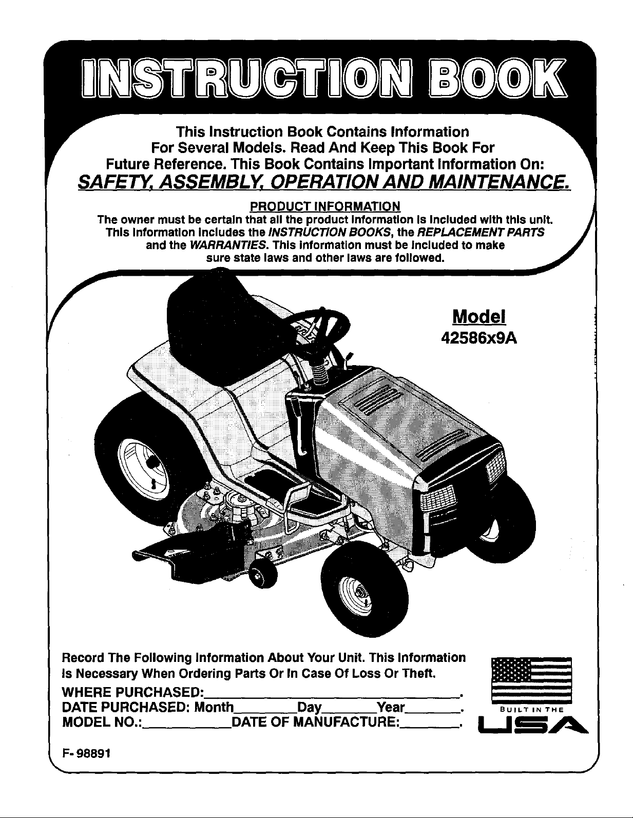
This Instruction Book Contains Information
For Several Models. Read And Keep This Book For
Future Reference. This Book Contains Important Information On:
SAFETY, ASSEMBLY, OPERATION AND MAINTENANCE.
PRODUCT INFORMATION
The owner must be certain that all the product Information Is Included with this unit.
This InformaUon includes the INSTRUCTION BOOKS, the REPLACEMENT PARTS
and the WARRANTIES. This information must be Included to make
sure state laws and other laws are followed.
Model
42586x9A
Record The Following Information About Your Unit. This Information
Is Necessary When Ordering Parts Or In Case Of Loss Or Theft.
WHERE PURCHASED:
DATE PURCHASED: Month Day Year
MODEL NO.: DATE OF MANUFACTURE:
F- 98891
BUILT IN THE
Page 2
TABLE OF CONTENTS
WARRANTY ......................................... 2
RESPONSIBILITY OF THE OWNER .................... 3
SAFETY RULES ..................................... 3
ASSEMBLY .......................................... 9
PARTS BAG - CONTENTS ................................ 9
CHECK THE TIRES ...................................... 9
CHECK THE LEVELOF THE MOWER HOUSING ............ 9
HOW TO INSTALL THE SEAT.............................. lO
HOW TO ASSEMBLE THE STEERING WHEEL .............. 10
HOWTO ASSEMBLE THE GAUGE WHEELS ................ 10
MAINTENANCE FREE BATrERY .......................... 11
HOWTO PREPARE THE ENGINE .......................... 11
IMPORTANTI BEFORE YOU START MOWING .............. 11
OPERATION ......................................... 12
LOCATION OF CONTROLS ............................... 12
ATTACHMENTS .......................................... 13
HOW TO USE THE THROTTLE CONTROL .................. 13
HOW TO USE THE BLADE ROTATION CONTROL ........... 13
HOW TO USE THE SPEED CONTROL PEDAL ............... 14
HOW TO DISCONNECT THE TRANSMISSION ............... 14
HOW TO SET THE PARKING DRAKE ....................... 15
HOW TO CHANGE THE CUTTING HEIGHT .................. 15
HOW TO STOP THE UNIT ................................. 16
HOW TO TRANSPORT THE UNIT .......................... 16
HOW TO OPERATE WITH THE MOWER HOUSING ........... 16
HOW TO OPERATE THE UNIT ON HILLS .... _.............. 16
BEFORE STARTING THE ENGINE ......................... 17
HOW TO START THE ENGINE ............................. 17
OPERATING TIPS ........................................ 18
MOWING AND BAGGING TIPS ............................ 18
HOW TO CHANGE THE MULCHER PLATE .................. 19
MAINTENANCE ...................................... 20
MAINTENANCE CHART .................................. 20
HOW TO CHECK THE MUFFLER .......................... 20
HOW TO REMOVE AND INSTALL THE BLADE .............. 21
HOW TO SHARPEN THE BLADE .......................... 21
HOW TO ADJUST THE BLADE ROTATION CONTROL ........ 22
HOW TO CHECK AND ADJUST THE DRIVE BRAKE ......... 23
HOW TO CHECK AND ADJUST THE MOTION DRIVE BELT . . . 23
HOW TO ADJUST THE SPEED CONTROL PEDAL ........... 24
MAINTENANCE FREE BAI"rERY .......................... 24
HOW TO CHARGE THE BATTERY ......................... 24
WHERE TO LUBRICATE .................................. 25
HOW TO CHECK THE FUEL FILTER ....................... 25
CHECK THE TIRES ...................................... 25
ROW TO REMOVE THE MOWER HOUSING ................. 26
HOW TO INSTALL THE MOWER HOUSING ................. 26
HOW TO LEVEL THE MOWER HOUSING ................... 27
HOW TO REPLACE THE MOTION DRIVE BELT .............. 28
HOW TO REPLACE THE MOWER DRWE BELT .............. 29
HOW TO REPLACE THE FUSE ............................ 30
HOW TO REPLACE THE LIGHT BULB ...................... 30
HOW TO CLEAN THE MOWER HOUSING ................... 30
STORAGE (OVER 30 DAYS) ............................... 30
TROUBLE SHOOTING CHART ........................ 31
SLOPE GUIDE ....................................... 32
INDEX .............................................. 35
LAWN TRACTOR ACCESSORIES ...................... 36
MURRAY, INC. Two Year Limited Warranty
Murray, Inc. warrants to the original purchaser that this unit shall befree from defects inmaterial and workmanship under normal
use and service for a period of Two (2) Years from the date of purchase; however, this warranty does not cover engines,
accessories (such as snow blowers, snow blades, grass baggers and plows), transmissions, batteries and Normal Wear Parts
(except as noted below) or transaxles as the companies that manufacture these items furnishtheir own warranties and provide
service through their authorized field service facilities. For additional information, see the warranties covering these particular
parts. If you are uncertain whether your unit contains or is equipped with one or more of these parts, consult your dealer prior
to purchase. Subject to the terms and conditions noted inthis LimitedWarranty, we shall, at our option, repair or replace at no
cost to the original purchaser any part covered by this LimitedWarranty duringthe applicable warranty period.
In the event the battery proves defective within ninety (90) days from the date of purchase, we wilt replace itwithout charge. If
the battery proves defective after (90) days but within one hundred twenty (120) days from the date of purchase, we willreplace
it for a charge of one half (1/2) of the retailprice of the battery in affect at the time of return.
Normal Wear Parts are defined as belts, blades, blade adapters, pneumatic tires, headlights and seat covers. These parts are
warranted tobe free from defects in material and workmanship as delivered withthe product.Any claim for repair or replacement
of Normal Wear Parts must be made within thirty (30) days of the date of purchase. No claims involvingdamage caused from
material use, abuse or misuse will be honored.
This Murray, Inc. Two (2) Year Limited Warranty is your exclusive remedy; however, this warranty isvoid or does not apply
to any unitthat has been tampered with, altered, misused, abused or used for rental or other commercial and/or professional
(non- homeowner) uses. Yourwarranty does not cover minor mechanical adjustments which are notdueto anydefect inmaterial
or workmanship. For assistance in making such adjustments, consult your Instruction Book.
Tomake aclaim under this Murray, Inc. Two (2) Year Limited Warranty, returnthe unit(or ifauthorized inadvance, the defective
part) along with your proof of purchase to an Authorized Service Center near you. To locate the nearest Authodzad Service
Center, call the Central Parts Distributor foryour area shown in the listprovided with your unit or check the Yellow Page listings
in your local telephone directory. If you return the entire unit, we will repair the unit. Ifwe authorize the return of the defective
part only, we will either replace orrepair the part. Inthe case of a defect in a transmission or differential (as distinguished from
a transaxle), the entire transmission or differential must be returned since they do netinclude userserviceable parts.
This Murray, Inc. Two (2) Year Limited Warranty gives you specific legal rights, and you may also have other rightswhich vary
from state to state. This Limited Warranty is given in lieu of all other expressed and implied warranties including the
implied warranty of merchantability and warranty of fitness for a particular purpose. If you need additional information
on this written warranty or assistance in obtaining service, write or call: MURRAY, INC., Outdoor Power Equipment, Customer
Service Department, P.O. Box 268, Brentwood, Tennessee 37027. (1o800- 251- 8007)
F-98891 2
Page 3
OWNER'S INFORMATION
This instruction book is for several different models. The instructions
are written for a person with some mechanical ability.Like most ser-
vicebooks, not all th• steps are described. Steps onhow to loosenor
tighten fasteners are steps anyone can followwith some mechanical
ability.Read and followthese instructionsbefore you usethe unit.
Knowyourproduct: Ifyou understandthe unitand howthe unitoper-
ates, youwillget thebest performance.As you raadthis manual,com-
pare the illustrationsto the unit.Learn thelocation and the functionof
the controls.Tohelpprevent an accident, followthe operating instruc-
tions and the safety rules. Keep this manual for future reference.
IMPORTANT: Many units are not assembled and are sold in car-
tons, It is the responsibility of the owner to make sure the assembly
instructionsin this manual are exactlyfollowed. Other unitsare put-
RESPONSIBILITY OF THE OWNER
The responsibility of the owner is to follow the instm_ons below.
1. Carefully read and follow the rules for safe operation.
2. Follow all the assembly instructions.
3. Inspect the unit.
4. Make sure that the operator of the unit knows how to correctly
use all standard and accessory equipment.
5. Operate the unit only with guards, shields, and other safety
items in place and working correctly.
6. Correctly adjust the unit.
7. Service the unitonly with authorized or approved replacement
parts,
8. Complete all maintenance on the unit.
chased inan assembled condition. On assembled units, it is the re-
sponsibility of the owner to make sure the unit is correctly
assembled. The owner must carefully check the unit according to
the instructions inthis manual before it isfirst used.
Environmental Awareness
• Do not fill the engine's fuel tank completely full.
• Drain fuel for off- season storage.
• Use only unleaded gasoline.
• Service the air cleaner regularly.
• Change oil regulady. Use t 0W- 30 oil in summer.
• Tune-upthe engine regularly.
• Keep equipment in efficient operating condition.
• Dispose of used engine oil properly.
SAFETY RULES
Safe Operation Practices for Ride- on Mower•
A
I. General operation
1. Read, understand and follow allinstructions inthe InstructionBook, onthe machine, the engine and withany attachmentabeforestarting.
2. Only allow responsible adults, who are familiar with the instructions,to operate the machine.
3. Clear the area of objects such as rocks, toys, wire, etc., which could be picked up and thrown by the blade.
4. Be sure the area is clear of other people before mowing. Stop the machine ifanyone enters the area.
5. Never carry passengers.
6. Tum off power tothe blades or any attachments before backing up,Do not mow in reverse unless absolutely necessary. Always look
7. Be aware ofthe mower discharge direction and do not point itat anyone. Do not operate the mowerwithout either the entire grass bagger
8. Slow down beforetuming.
9. Never leave a machine unattended with the engine running.Always tum offthe blade(s), set the parking brake, stop the engine and
10. Turn off power to attachment(s) when transporting or not in use. Tum off the blade(s) when not mowing.
11. Stop the engine before ramoving the grass bagger or unclogging the chute.
12. Mow only in daylight or good artificial light.
13. Do not operate the machine while under the influence of alcohol or drugs or when very tired.
14. Watch fortraffic when operating near or crossing roadways.
15. Use extra caution when loading or unloading the machine into a traileror truck.
16. Turn off all attachment clutches before attempting to start the engine.
17. Always wear goggles, safety glasses, or an eye shield when you operate the unitto protect your eyes fromforeign objects that can be
18. Use care when pulling loads or using heavy equipment.
19. Do not operate this machine ifyou are taking drugs or other medication which can cause drowsiness or affect your ability to operate
F. 98891
WARNING: This cutting machine is capable of amputating hands and feet and throwing objects. Failure to observe the
following safety instructions could result in serious injury or death.
down and behind before and while backing.
or the mower guard in place.
remove the key before dismounting.
thrown from the unit.Always wear eye protection when you make an adjustment or repair to the machine.
a. Use only approved drawbar hitchpoints.
b. Limit loads to those you can safely control.
c. Do notturn sharply. Use care when backing.
d. Use counterweights or wheel weights when suggested inthe Instruction Book.
this machine.
Page 4
OWNER'S INFORMATION
20. Do not use this machine if you are mentally or physically unable to operate this machine safely.
II. Slope operation
Slopes and rough terrain are major factors related to loss- of- control and tip- over accidents, which can result in severe Injury
or death. ALL slopes require extra caution. If you cannot back up the slope or if you feel uneasy on the slope, do not mow it. See
the USlope Guide" in the back of this book to check for safe operation.
DO
1. Mow up and down slopes, not across.
2. Remove obstacles such as rocks, limbs, etc...
3. Watch for holes, ruts or bumps. Uneven terrain could overturn the machine. Tall grass can hide obstacles.
4. Use slow speed on slopes. Do not make sudden speed changes.
5. Follow the manufacturer's recommendations for wheel weights or counterweights to improve stability.
6. Use extra care with grass baggers or other attachments, they can change the stabilityof the machine.
7. Keep all movement on the slopes slow and gradual. Do not make sudden changes In speed or direction.
8. Avoid starting or stopping on a slope. If tires lose traction, turn off the blades and proceed slowly straight down the slope.
DO NOT
1. Do not turn on slopes unless absolutely necessary, then only turn slowly and gradually downhill, if possible.
2. Do not mow drop- offs, ditches or embankments. A wheel over the edge or an edge caving in could cause a sudden overturn and an
injuryor death.
3. Do not mow on wet grass. Reduced traction could cause sliding.
4. Do not try to stabilize the machine by putting your foot on the ground.
5. Do not use a grass bagger or other rear mounted accessories on steep slopes (greater than 10 degrees).
III. Children
Tragic accidents can occur if the operator is not alert to the presence of children. Children are often attracted to the machine and
the mowing activity. NEVER assume that children will remain where you last saw them.
1. Keep childrenout of the mowing area and in the watchful care of another responsible adult.
2. Be alert and turn the engine off ifchildren enter the area.
3. Before and when backing, look behind and down for small children.
4. Never carry children or any passengers, even with the blades off. They may fall off and be seriously injured or Interfere with the safe
operation of the machine.
5. Never allow children to operate the machine. Instructchildren inthe potential dangers ofthe machine.
6. Use extra care when approaching blind corners, shrubs, trees or other objects that may obscure vision.
IV. Service
1. Use extra care when handling gasoline and other fuels. Fuels are flammable and the vapors are explosive.
a. Use only an approved container.
b. Never remove the gas cap or add fuel with the engine running. Allow the engine to cool for several minutes before refueling. Do
not smoke.
c. Never rsfuelths machine indoors.
d. Never store the machine with fuel inthe tank or fuel container inside where there is an open flame, such as a water heater.
2. Never start or run the engine inside a closed area.
3. Keep all nutsand bolts, especially the blade attachment nutstight. Frequently check the blade(s) for wear or damage such as cracks
and nicks.A blade that is bent or damaged mustbe immediately replaced with an original equipment blade from an authorized service
dealer. For safety, replace the blade every two years. Keep the equipment in good condition.
4. Never tamper with the safety devices. Check their proper operation regularly.
5. To reduce fire hazards, keep the machine free of grass, leaves or other debris build- up. Clean up oil or fuel spills.Allow the machine
to cool before storing.
6. Stop and inspect the equipment if you strike an object. Repair, if necessary, before restarting.
7. Never make adjustments or repairs with the engine running. The carburetor can be adjusted with the engine running. Do not change
the engine governor settings or over- speed the engine.
8. Grass bagger components are subject to wear, damage and deterioration, which could expose moving parts or allow objects to be
thrown. For storage, always make sure the grass bag is empty. Frequently check components and replace with manufacturer's recom-
mended parts when necessary.
9. Mower blade(s)are sharp and can cut.Wrapthe blade(s)orwear glovesand use extra cautionwhen servicing them orths blade housing
area.
10. Check the brake operation frequently. Adjust and service as required.
11. Wait for all movement to stop befere servicing any part of the unit.
F- 98891
precautions. This symbol indicates: UAttention!
Look for this symbol to indicate important safety
Become Alert! Your Safety Is At Risk."
Page 5
SAFE MOWING GUIDE
Eachpemonthatoperatespower
equipmentmustlearnto usecorrectand
safe mowingprocedures.To help you
learn, carefully read the following
pages. Mostofthetime theoperatorwas
notcorrectlyshownordidnotreadthe
instructionsontheunitor inthe Instruction
Bookbeforeusingtheunit.Also,some
operatorsdonothave enoughexperience.
The resultisunsafeuse,endangeringthe
operator,bystandersandthe equipment.
Anotherresultcan be a poorappearance
ofthe area mowed.
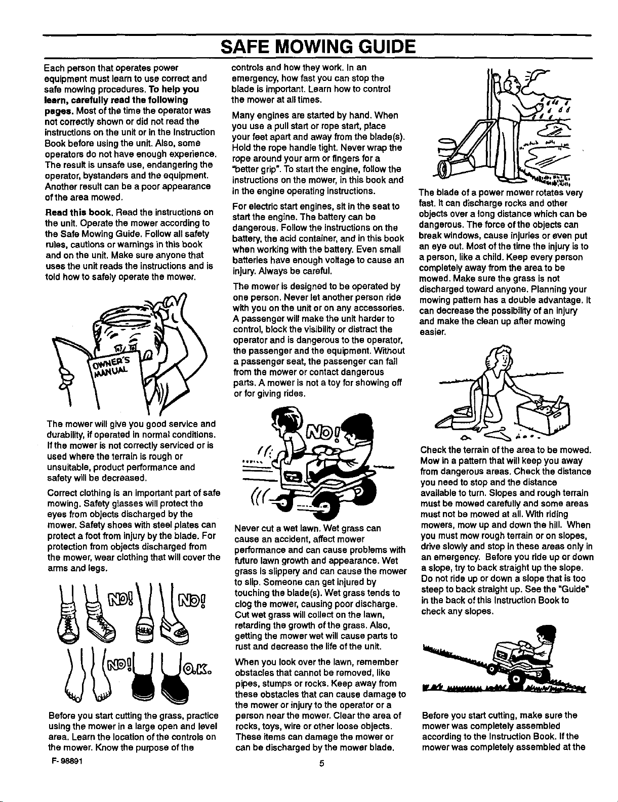
Read this book. Read the instructions on
the unit. Operate the mower according to
the Safe Mowing Guide. Follow all safety
rules, cautions or warnings in this book
and onthe unit. Make sure anyone that
uses the unit reads the instructions and is
told howto safely operate the mower.
controls and how they work. Inan
emergency, how fast you can stop the
blade is important. Learn how to control
the mower at all times.
Many engines are started by hand. When
you use a pull start or rope start, place
your feet apart and away from the blade(s).
Hold the rope handle tight. Never wrap the
rope around your arm or fingers for a
=better grip".To start the engine, followthe
instructions on the mower, inthis book and
in the engine operating instructions.
For electric start engines, sit inthe seat to
start the engine. The battery can be
dangerous, Follow the instructions on the
battery, the acid container, and inthis book
when working with the battery. Even small
batteries have enough voltage to cause an
injury.Always be careful.
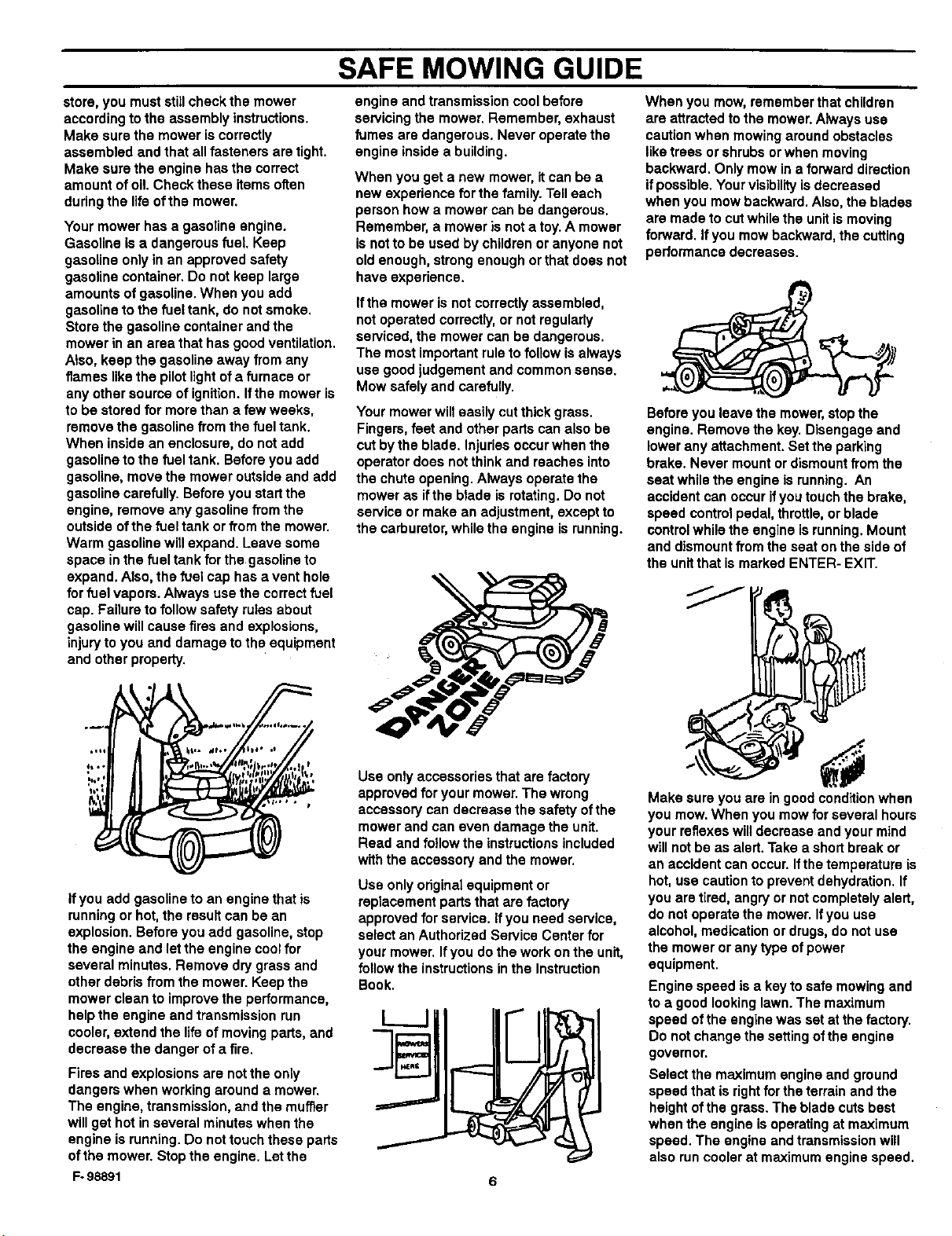
The mower is designed to be operated by
one person. Never let another person ride
with you onthe unit or on any accessories.
A passenger will make the unit harder to
control, block the visibilityor distract the
operator and is dangerous to the operator,
the passenger and the equipment. Without
a passenger seat, the passenger can fall
from the mower or contact dangerous
parts. A mower is not a toy for showing off
or for giving rides.
The blade of a power mower rotates very
fast. It can discharge rocks and other
objects over a long distance which can be
dangerous. The force of the objects can
break windows, cause injuriesor even put
an eye out. Most of the time the injuryis to
a person, likea child. Keep every person
completely away from the area to be
mowed. Make sure the grass is not
discharged toward anyone. Planning your
mowing pattern has a double advantage. It
can decrease the possibilityof an injury
and make the clean up after mowing
easier.
The mowerwillgiveyougoodserviceand
durability,if operatedinnormalconditions.
Ifthe moweris notcorrectlyservicedoris
usedwheretheterrainis roughor
unsuitable,productperformanceand
safetywillbe decreased.
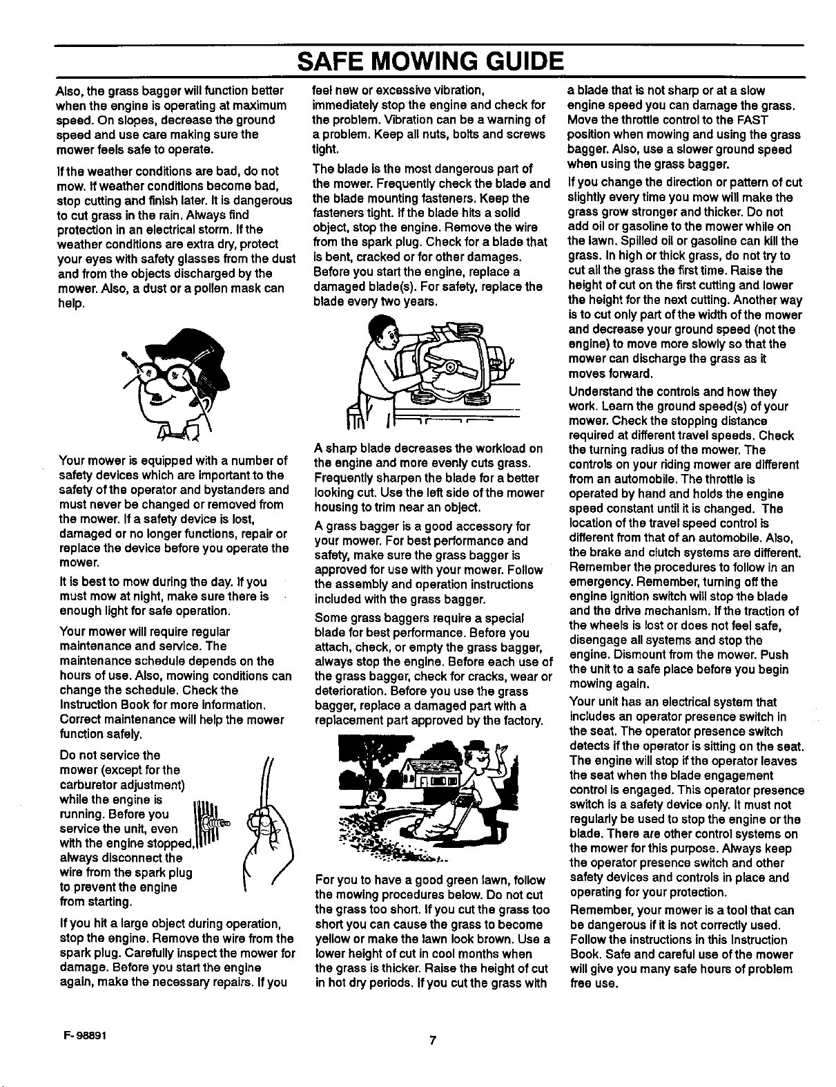
Correct clothing isan important partof safe
mowing. Safety glasses willprotect the
eyes from objects discharged bythe
mower. Safety shoes with steel plates can
protect a foot from injuryby the blade. For
protection from objects discharged from
the mower, wear clothing that will cover the
arms and legs.
Before you start cuttingthe grass, practice
using the mower in a large open and level
area. Learn the location ofthe controls on
the mower. Know the purpose of the
F- 98891
/(.,
Never cut a wet lawn. Wet grass can
cause an accident, affect mower
performance and can cause problems with
future lawn growth and appearance. Wet
grass isslippery and can cause the mower
to slip. Someone can get injured by
touching the blade(s). Wet grass tends to
clogthe mower, causing poor discharge.
Cut wet grass will collect on the lawn,
retarding the growth of the grass. Also.
getting the mower wet will cause parts to
rust and decrease the lifeof the unit.
When you look over the lawn, remember
obstacles that cannot be removed, like
pipes, stumps or rocks. Keep away from
these obstacles that can cause damage to
the mower or injuryto the operator ora
person near the mower. Clear the area of
rocks, toys, wire orother looseobjects.
These items can damage the mower or
can be discharged bythe mower blade.
5
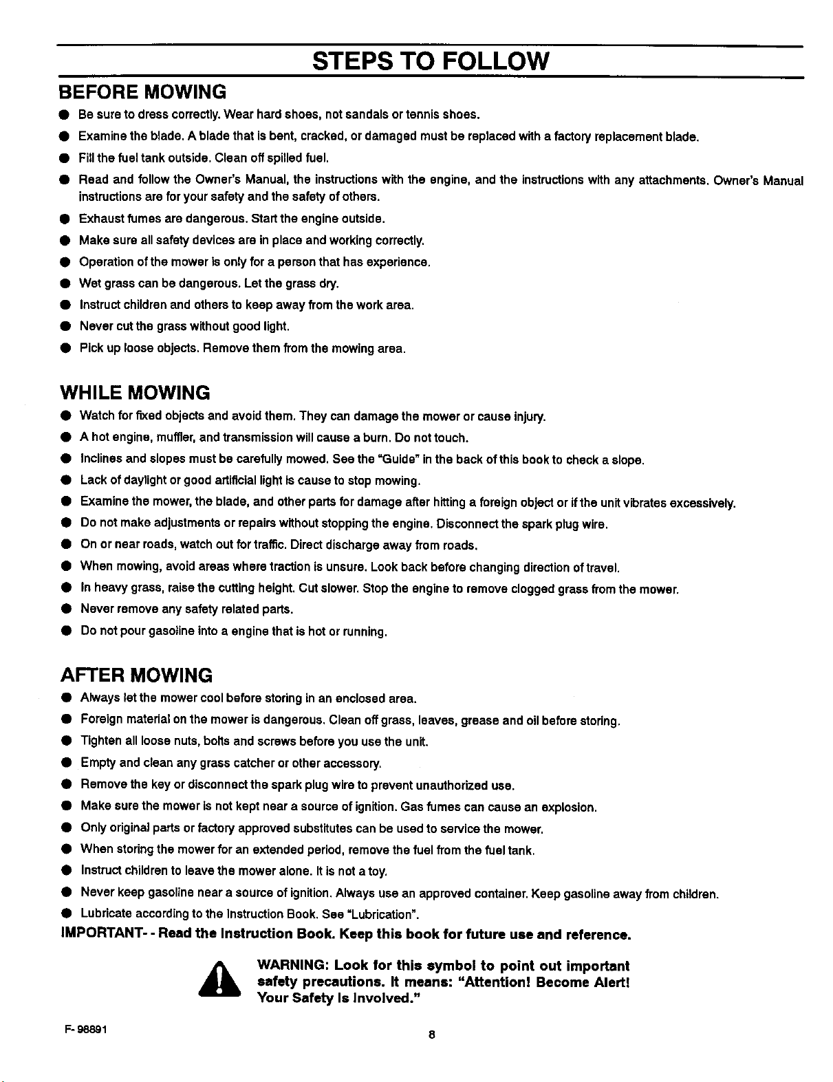
Check the terrain ofthe area to be mowed.
Mow in a pattern that will keep you away
from dangerous areas. Check the distance
you need to stop and the distance
available to turn. Slopes and rough terrain
must be mowed carefully and some areas
must not be mowed at all. With riding
mowers, mow up and down the hill. When
you must mow rough terrain or on slopes,
dYNeslowly and stop in these areas only in
an emergency, Before you ride up or down
a slope, tryto back straight up the slope.
Do not ride up or down a slope that is too
steep to back straight up. See the "Guide*
in the back of this Instruction Book to
check any slopes.
Before you start cutting, make sure the
mower was completely assembled
according to the Instruction Book. If the
mower was completely assembled at the
Page 6
SAFE MOWING GUIDE
store,youmuststillcheckthemower
accordingtotheassemblyinstructions.
Makesurethemoweriscorrectly
assembled and that all fasteners are tight.
Make sure the engine has the correct
amount of oil. Check these items often
during the life of the mower.
Your mower has a gasoline engine.
Gasoline is a dangerous fuel. Keep
gasoline only in an approved safety
gasoline container. Do not keep large
amounts of gasoline. When you add
gasoline to the fuel tank, do notsmoke.
Store the gasoline container and the
mower in an area that has good ventilation.
Also, keep the gasoline away from any
flames likethe pilot light of a furnace or
any other source of ignition. If the mower is
to be stored for more than a few weeks,
remove the gasoline from the fuel tank.
When inside an enclosure, do not add
gasoline to the fueltank. Before you add
gasoline, move the mower outside and add
gasoline carefully. Before you start the
engine, remove any gasoline fTomthe
outside ofthe fuel tank orfrom the mower.
Warm gasoline will expand. Leave some
space in the fuel tank for the gasoline to
expand. Also, the fuel cap has a vent hole
for fuel vapors. Always use the correct fuel
cap. Failure to follow safety rules about
gasoline will cause fires and explosions,
injury to you and damage to th e equipment
and other property.
engine and transmission cool before
servicing the mower. Remember, exhaust
fumes are dangerous. Never operate the
engine inside a building.
When you get a new mower, itcan be a
new experience fur the family. Tell each
person how a mower can be dangerous.
Remember, a mower is nota toy.A mower
is not to be used by children or anyone not
old enough, strong enough orthat does not
have experience.
If the mower is not correctly assembled,
not operated correctly, or not regularly
serviced, the mower can be dangerous.
The most important rule to follow is always
usa good judgement and common sense.
Mow safely and carefully.
Your mower will easily cut thick grass.
Fingers, feet and other parts can also be
cut by the blade. Injuries occur when the
operator does not think and reaches into
the chute opening. Always operate the
mower as ifthe blade is rotating. Do not
service or make an adjustment, except to
the carburetor, while the engine is running.
When you mow, remember that children
are attracted to the mower.Always usa
caution when mowing around obstacles
like trees or shrubs or when moving
backward. Only mow ina forward direction
if possible. Yourvisibility is decreased
when you mow backward. Also, the blades
are made to cutwhile the unitis moving
forward. If you mow backward, the cutting
performance decreases.
Before you leave the mower,stop the
engine. Remove the key. Disengage and
lower any attachment. Set the parking
brake. Never mount or dismount from the
seat while the engine is running. An
accident can occur ifyou touch the brake,
speed control pedal, throttle, or blade
control while the engine is running. Mount
and dismount from the seat onthe side of
the unit that is marked ENTER- EXIT.
If you add gasoline to an engine that is
running or hot, the result can be an
explosion. Before you add gasoline, stop
the engine and let the engine cool for
several minutes. Remove dry grass and
other debris from the mower. Keep the
mower clean to improve the performance,
help the engine and transmission run
cooler, extend the life of moving parts, and
decrease the danger of a fire.
Fires and explosions are notthe only
dangers when working around a mower.
The engine, transmission, and the muffler
will get hot in several minutes when the
engine is running. Do not touch these parts
ofthe mower. Stop the engine. Let the
Fo98891
Usa only accessories that are factory
approved for your mower. The wrong
accessory can decrease the safety of the
mower and can even damage the unit.
Read and follow the instructions included
with the accessory and the mower.
Use only original equipment or
replacement parts that are factory
approved for service. If you need service,
select an Authorized Service Center for
your mower. If you do the work on the unit,
follow the instructions in the Instruction
Book.
6
Make sure you are in good condition when
you mow. When you mow forseveral hours
your reflexes will decrease and your mind
will not be as alert. Take a short break or
an accident can occur. Ifthe temperature is
hot, use caution to prevent dehydration. If
you are tired, angry or not completely alert,
do not operate the mower. If you use
alcohol, medication or drugs, do not use
the mower or any type of power
equipment.
Engine speed is a keyto safe mowing and
to a good looking lawn. The maximum
speed ofthe engine was set at the factory.
Do not change the settingof the engine
governor.
Select the maximum engine and ground
speed that is rightfor the terrain and the
height of the grass. The blade cuts best
when the engine isoperating at maximum
speed. The engine and transmission will
also run cooler at maximum engine speed.
Page 7
SAFE MOWING GUIDE
Also, the grass bagger will function better
when the engine is operating at maximum
speed. On slopes, decrease the ground
speed and use care making sure the
mower feels safe to operate.
Ifthe weather conditions are bad, do not
mow. Ifweather conditions become bad,
stop cutting and finish later. It isdangerous
to cut grass inthe rain. Always find
protection in an electrical storm. Ifthe
weather conditions are extra dry,protect
your eyes with safety glasses from the dust
and from the objects discharged by the
mower. Also, a dust or a pollen mask can
help.
Your mower is equipped with a number of
safety devices which are importantto the
safety ofthe operator and bystanders and
must never be changed or removed from
the mower. Ifa safety device is lost,
damaged or no longer functions, repair or
replace the device before you operate the
mower.
It is best to mow duringthe day. if you
must mow at night, make sure there is
enough lightfor safe operation.
Your mower will require regular
maintenance and service. The
maintenance schedule depends on the
hours of use. Also, mowing conditions can
change the schedule. Check the
Instruction Book for more information.
Correct maintenance will help the mower
function safely.
Do not service the
mower (except for the
carburetor adjustment)
while the engine is
service the unit, even _1_'_
with the engine stopped,ill_'"
always disconnect the
running. Beforeyou I_ I
wire from the spark plug
to prevent the engine
from starting.
Ifyou hita largeobjectduringoperation,
stoptha engine.Removethewire fromthe
sparkplug.Carefullyinspectthe mowerfor
damage.Beforeyoustartthe engine
again,make thenecessaryrepairs.Ifyou
feel new or excessive vibration,
immediately stop the engine and check for
the problem. Vibration can be a warning of
a problem. Keep all nuts, botts and screws
tight.
The blade is the most dangerous part of
the mower. Frequently check the blade and
the blade mounting fasteners. Keep the
fasteners tight. If the blade hits a solid
object, stop the engine. Remove the wire
from the spark plug. Check for a blade that
isbent, cracked or for other damages.
Before you start the engine, replace a
damaged blade(s). For safety, replace the
blade every two years.
A sharp blade decreases the workload on
the engine and more evenly cuts grass.
Frequently sharpen the blade for a better
looking cut. Use the leftside of the mower
housing to trim near an object.
A gross bagger is a good accessory for
your mower. For best performance and
safety, make sure the gross bagger is
approved for use with your mower. Follow
the assembly and operation instructions
included with the grass bagger.
Some grass baggers require a special
blade for best performance. Before you
attach, check, or empty the grass bagger,
always stop the engine. Before each use of
the grass bagger, check for cracks, wear or
deterioration. Before you use the grass
bagger, replace a damaged part with a
replacement part approved bythe factory.
For you to have a good green lawn, follow
the mowing procedures below. Do notcut
the grass too shod. If you cut the gross too
short you can cause the grass to become
yellow or make the lawn look brown. Usa a
lower height of cut in cool months when
the grass isthicker. Raise the height of cut
in hot dry periods. Ifyou cut the grass with
a blade that is not sharp or at a slow
engine speed you can damage the gross.
Move the throttle control to the FAST
position when mowing and using the grass
bagger. Also, use a slower ground speed
when usingthe gross bagger.
Ifyou change the direction or pattern of cut
slightly every time you mow will make the
gross grow stronger and thicker. Do not
add oil or gasoline to the mower while on
the lawn. Spilled oil or gasoline can killthe
grass. In high or thick gross, do not try to
cut all the grassthe firsttime. Raise the
height of cut on the first cutting and lower
the height for the next cutting.Another way
isto cut only part of the width of the mower
and decrease your ground speed (not the
engine) to move more slowly so that the
mower can discharge the grass as it
moves forward.
Understand the controls and how they
work. Learn the ground speed(s) of your
mower. Check the stopping distance
required at differenttravel speeds. Check
the turning radius ofthe mower. The
controls onyour ridingmower are different
from an automobile. The throttle is
operated by hand and holds the engine
speed constant until it is changed. The
location of the travel speed control is
different from that of an automobile. Also,
the brake and clutch systems are different.
Remember the procedures to follow in an
emergency. Remember, turning off the
engine ignitionswttchwill stopthe blade
and the drive mechanism. Ifthe traction of
the wheels is lost or does not feel safe,
disengage all systems and stop the
engine. Dismount from the mower. Push
the unitto a safe place before you begin
mowing again.
Your unit has an electrical system that
includes an operator presence switch in
the seat. The operator presence switch
detects ifthe operator is sitting on the seat.
The engine will stop if the operator leaves
the seat when the blade engagement
control is engaged. This operator presence
switch is a safety device only. It must not
regularly be used to stop the engine or the
blade. There are other controlsystems on
the mower for thispurpose. Always keep
the operator presence switch and other
safety devices and controls in place and
operating for yourprotection.
Remember, your mower is a tool that can
be dangerous if itis not correctly used.
Follow the instructionsin this Instruction
Book. Safe and careful use ofthe mower
will give you many safe hours of problem
free use.
F- 98891 7
Page 8
STEPS TO FOLLOW
BEFORE MOWING
• Be sure to dress correctly. Wear hard shoes, notsandals ortennis shoes.
• Examine the blade. A blade that isbent, cracked, or damaged must be replaced with a factory replacement blade.
• FlUthe fuel tank outside. Clean off spilled fuel.
• Read and follow the Owner's Manual, the instructions with the engine, and the instructionswith any attachments. Owner's Manual
instructions are for your safety and the safety ofothers.
• Exhaust fumes ara dangeraus. Start the engine outside.
• Make sure all safety devices are in place and working correctly.
• Operation of the mower Is only for a person that has experience.
• Wet grass can be dangerous. Let the grass dry.
• Instruct children and others to keep away from the work area.
• Never cut the grasswithout good light.
• Pick up loose objects. Remove them from the mowing area.
WHILE MOWING
• Watch for fixed objects and avoid them. They can damage the mower or cause injury.
• A hot engine, muffler,and transmission will cause a burn. Do not touch.
• Inclines and slopes must be carefully mowed. See the "Guide" in the back ofthis book to check a slope.
• Lack of daylight or good artificial lightis cause to stop mowing.
• Examine the mower, the blade, and other parts for damage after hittinga foreign object or ifthe unit vibrates excessively.
• Do not make adjustments or ropairs without stopping the engine. Disconnect the spark plug wire.
• On or near roads, watch out for traffic. Direct discharge away from roads.
• When mowing, avoid areas where traction is unsure. Look back before changing direction oftravel.
• Inheavy grass, raise the cutting height. Cut slower. Stop the engine to remove clogged grass from the mower.
• Never remove any safety related parts.
• Do not pour gasoline into a engine that is hot or running.
AFTER MOWING
• Always let the mower cool before storing in an enclosed area.
• Foreign material onthe mower is dangerous. Clean off grass, leaves, grease and oil before storing.
• Tighten all loose nuts, bolts and screws before you use the unit.
• Empty and clean any grass catcher or other accessory+
• Remove the key or disconnect the spark plug wire to prevent unauthorized use.
• Make sure the mower Is not kept near a source of ignition. Gas fumes can cause an explosion.
• Only original parts or factory approved substitutes can be used to service the mower.
• When storing the mower for an extended period, remove the fuel from the fuel tank.
• Instructchildren to leave the mower alone. Itis not a toy.
• Never keep gasoline near a source of ignition.Always use an approved container. Keep gasoline away from children.
• Lubricate according to the Instruction Book. See =Lubrication".
IMPORTANT- - Read the Instruction Book. Keep this book for future use and reference.
,_ WARNING: Look for this symbol to point out important
1=-98891 8
safety precautions. It means: "Attention! Become Alertt
Your Safety Is Involved."
Page 9
ASSEMBLY
ASSEMBLY
This instruction book isfor several models. Some parts oraccesso-
ries are not included on all models. Read and follow the assembly
and adjustment instructions for your mower. All fasteners are in the
parts bag. Do not discard any parts or material until the unit is
assembled.
4_b WARNING: Before doing any assembly or mainte-
NOTE: In this instruction book, left and right describe the loca-
tion of a part with the operator on the seat.
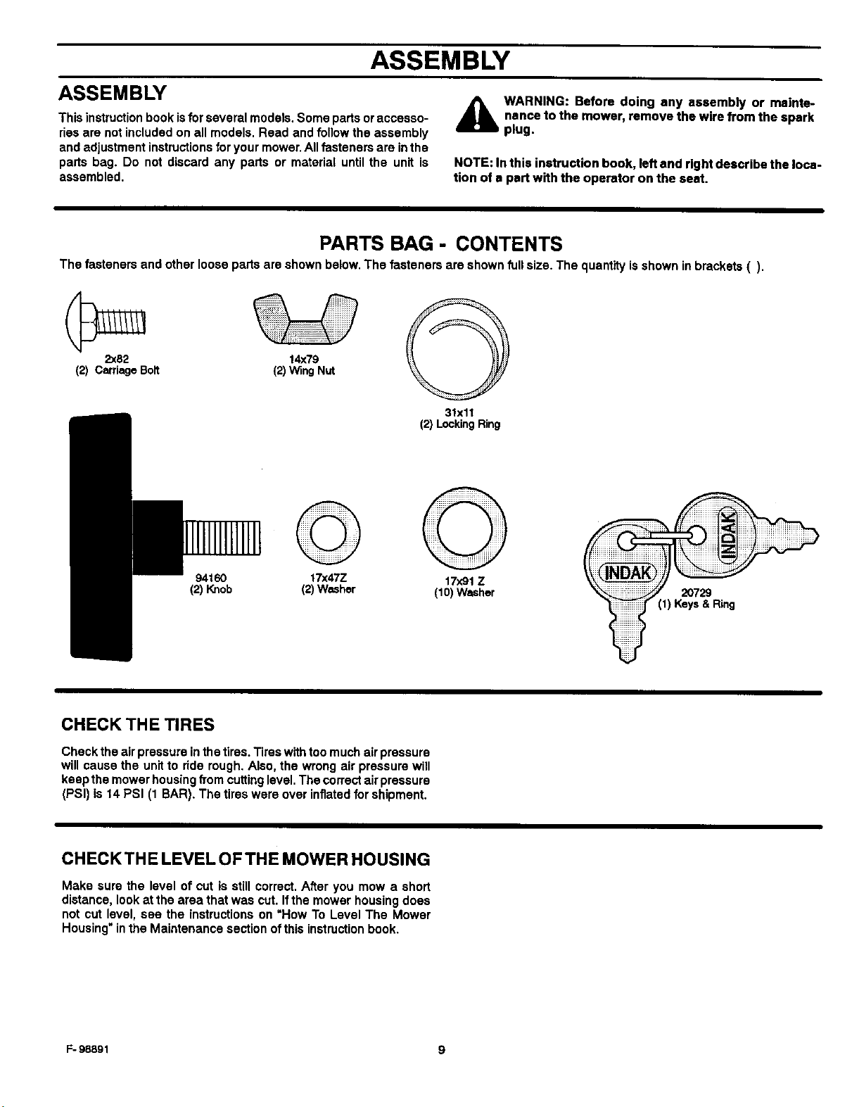
PARTS BAG - CONTENTS
The fasteners and other loose parts are shown below. The fasteners are shown full size. The quantity is shown inbrackets ().
2x82 14x79
(2) CarriageBolt (2)WingNut
31xli
(2) LockingRing
nance to the mower, remove the wire from the spark
plug,
©
94160
(2)Knob
CHECK THE TIRES
Check the air pressure in the tires. Tires with too much air pressure
will cause the unit to ride rough. Also, the wrong air pressure will
keep the mower housing fTomcutting level. The correct air pressure
(PSI) is 14 PSI (1 BAR). The tires were over inflated for shipment.
CHECKTHE LEVEL OF THE MOWER HOUSING
Make sure the level of cut is still correct. After you mow a short
distance, look at the area that was cut. If the mower housing does
not cut level, see the instructions on =How To Level The Mower
Housing" in the Maintenance section of this instruction book.
17x47Z
(2)Washer
17x91Z
(1O)Washer 20729
(1) Keys& Ring
F- 98891 9
Page 10
ASSEMBLY
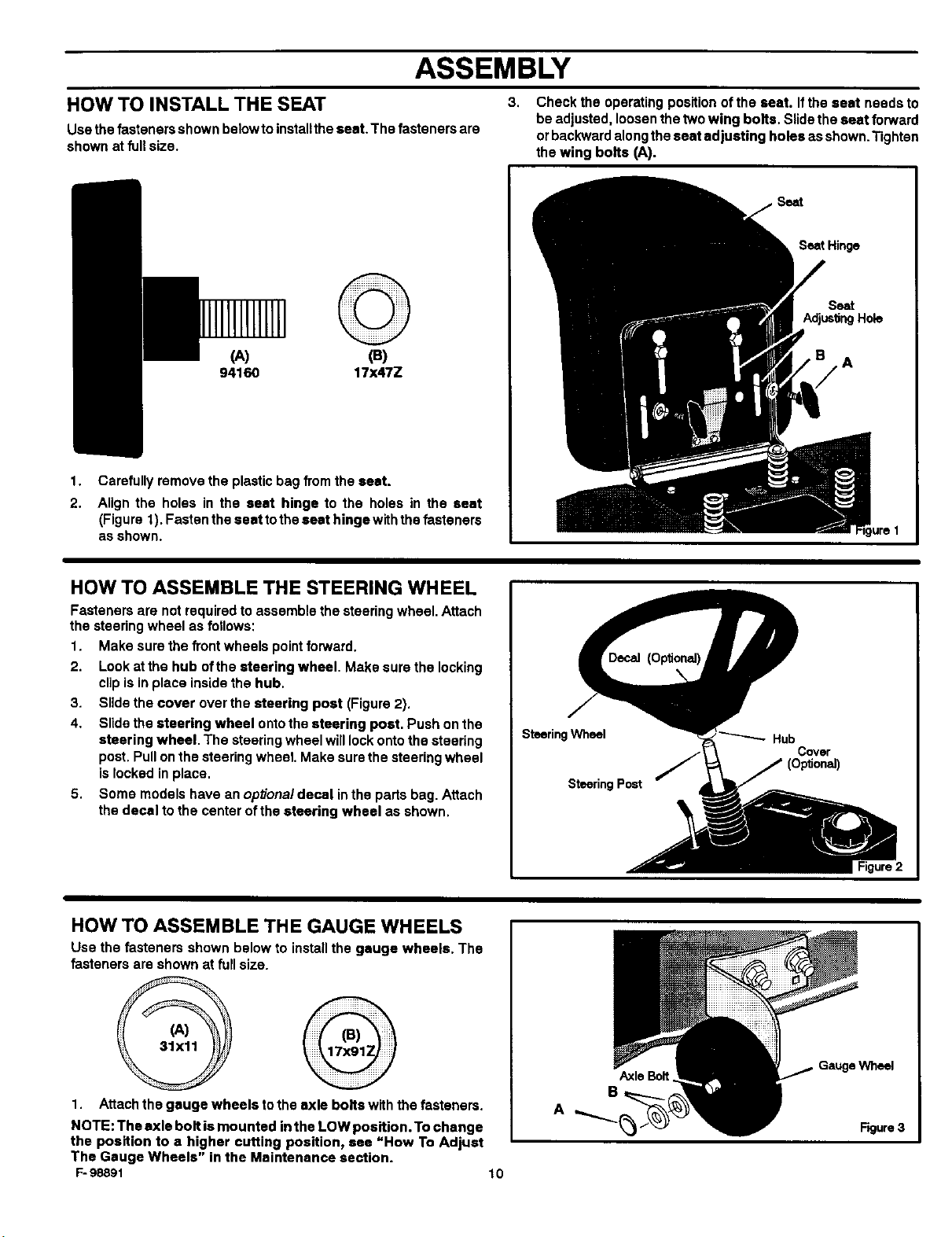
HOW TO INSTALL THE SEAT
Use thefasteners shown below to installthe seat. The fasteners are
shown at fullsize.
©
(A) (B)
94160 17x47Z
1,
Carefully remove the plastic bag from the seat.
2.
Align the holes in the seat hinge to the holes in the seat
(Figure 1). Fasten the seat tothe seat hinge with the fasteners
as shown.
3.
Check the operating position of the seat. If the seat needs to
be adjusted, loosen the two wing bolts. Slide the seat forward
orbackward along the seat adjusting heles as shown."fighten
the wing bolts (A).
Seat Hinge
Seat
,A
I Hole
HOW TO ASSEMBLE THE STEERING WHEEL
Fasteners are not required to assemble the steering wheel. Attach
the steering wheel as follows:
1. Make sure the front wheels point forward.
2. Look at the hub ofthe steering wheel. Make sure the locking
clipis in place inside the hub.
3. Slide the cover over the steering post (Figure 2).
4, Slide the steering wheel onto the steering post. Push on the
steering wheel. The steering wheel will lock onto the steering
post. Pull on the steering wheel. Make sure the steering wheel
is locked in place.
5. Some models have an optional decal in the parts bag. Attach
the decal to the center of the steering wheel as shown.
HOW TO ASSEMBLE THE GAUGE WHEELS
Use the fasteners shown below to installthe gauge wheels, The
fasteners are shown at full size.
Steering Wheel
Steering Post
Hub
Covor
1. Attach the gauge wheels to the axle bolts with the fasteners.
NOTE: The axle bolt is mounted inthe LOW position. To change
the position to a higher cutting position, see "How To Adjust
The Gauge Wheels" in the Maintenance section.
F-98891 10
AxleBolt
Wheel
Figure 3
Page 11
ASSEMBLY
MAINTENANCE FREE BATTERY HOW TO CHARGE THE MAINTENANCEFREEBATTERY
IMPORTANT: Before you attach the battery cables to the A
battery, cheek the battery date. The battery date tells if the
battery must be charged.
1. Check the top of the battery for the location of the battery date 1.
(Figure 4).
2. If the battery is put into service before the battery date, the 2.
battery cables can be attached without charging the battery. 3.
See =How To InstallThe Battery Cables'.
3. If the battery is put into service after the battery date, the
battery must be charged. See "How To Charge The 4.
Maintenance Free Battery".
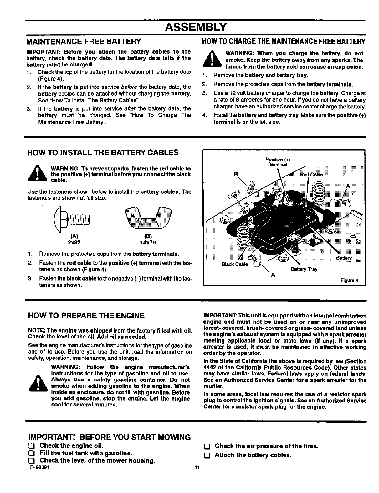
HOW TO INSTALL THE BATTERY CABLES
A WARNING: To prevent sparks, fasten the red cable to
Use the fasteners shown below to install the battery cables. The
fasteners are shown at full size.
the positive (+) terminal before you connect the black
cable.
WARNING: When you charge the battery, do not
smoke. Keep the battery away from any sparks. The
fumes from the battery acid can cause an explosion.
Remove the battery and battery tray.
Remove the protective caps from the battery terminals.
Use a 12 voltbattery charger to charge the battery. Charge at
a rate of 6 amperes for one hour. If you do not have a battery
charger, have an authorized service center charge the battery.
Installthe battery and battery tray. Make surethe positive (+)
terminal is onthe leftside.
Po=itive(+)
Terminal
B
tiiiiiiii
\
I
(A) (a)
2x82 14x79
1. Remove the protective caps from the battery terminals.
2. Fasten the red cable to the positive (+) terminal with the fas-
teners as shown (Figure 4).
3. Fasten the black cable tothe negative (-) terminalwlth the fas-
teners as shown.
HOW TO PREPARE THE ENGINE
NOTE: The engine was shipped from the factory filled with oil.
Check the level of the oil. Add oil as needed.
See the engine manufacturer's instructions forthe type of gasoline
and oil to use. Before you use the unit, read the information on
safety, operation, maintenance, and storage.
WARNING: Follow the engine manufacturer's
instructions for the type of gasoline and oil to use.
Always use a safety gasoline container. Do not
A
smoke when adding gasoline to the engine. When
inside an enclosure, do not fill with gasoline. Before
you add gasoline, stop the engine. Let the engine
cool for several minutes.
Black Cable
iiiBatteryiiiiiiiiiii
BatteryTray
A
Figure4
IMPORTANT: This unit is equipped with an internal combustion
engine and must not be used on or near any unimproved
forest- covered, brush- covered or grass- covered land unless
the engine's exhaust system is equipped with a spark srrester
meeting applicable local or state laws ('If any). if a spark
errester is used, it must be maintained in effective working
order by the operator.
In the State of California the above is required by law (Section
4442 of the California Public Resources Code). Other states
may have similar laws. Federal laws apply on federal lands.
See an Authorized Service Center for a spark arrester for the
muffler.
In some areas, local law requires the use of a resistor spark
plug to control the ignition signals. See an Authorized Service
Center for a resistor spark plug for the engine.
IMPORTANT! BEFORE YOU START MOWING
Check the engine oil.
0 Fill the fuel tank with gasoline.
[] Check the level of the mower housing.
F. 98891
[] Check the air pressure of the tires.
[] Attach the battery cables.
11
Page 12

Throttle Control
Lever
Brake Pedal
OPERATION
BladeRotation
Control
Pedal
Lift
Lever
LOCATION OF CONTROLS
BLADE ROTATION CONTROL: usethebladerotation
control to start and stopthe rotation of the blades.
BRAKE PEDAL: Use the brake pedal to quicklystop.
HEADLIGHT SWITCH: The headlight switch isthe firstpart
ofthe ignitionswitch. To use the lightswith the engine running, turn
the key to the positionfor the lights.
Figure 5
AUTOMATIC DRIVE DISCONNECT: usetheauto-
maticdrive disconnect, located under the seat, to disengage the
transmission.
LIFT LEVER: use the lift lever to change the heightof cut,
PARKING BRAKE LEVER: usethe parkingbrakelever
to engage the brake when you leave the unit.
SPEED CONTROL PEDAL: usethespeedcontrolpedal
to change the speed and the direction of the unit,
IGNITION SWITCH: Usetheignitionswitchtostartandstop
the engine.
F- 9889 t 12
THROTTLE CONTROL LEVER: Usethethrottlecontrol
lever to increase or decrease the speed ofthe engine,
Page 13

OPERATION
ATTACHMENTS HOW TO USE THE BLADE ROTATIONCONTROL
This unit can use many different attachments See the attachment
page in this book. This unit can pull attachments like a lawn
sweeper, a lawn aerator, or a hopper spreader. This unitcan notuse
attachments that engage the ground like a plow, a disk harrow, or
a cuitNator
HOW TO USE THE THRO'I-rLE CONTROL
Use the throttle control to increase or decrease the speed ofthe
engine.
CAUTION: Always operate the engine with the throttle control
in the FAST position. If the engine runs for several minutes at
slower than the FAST position, the engine and transmission
will overheat and can be damaged.
The FAST position is marked with a detent For normal opera-
tion and when using a grass bagger, move the throttle control
to the FAST position For maximum charging ofthe battery and
for a cooler running engine and transmission, operate the en-
gine in the FAST position.
2
For transport and to tow pull behind attachments, control the
ground speed with the speed control pedal.
3
The engine governor is set at the factory for maximum perform-
ance Do not adjust the governor to increase the speed ofthe
engine
The blade rotation control is next to the steenng wheel (Figure 6).
Use the blade rotation controlto engage the blade(s) orto operate
a snow thrower attachment.
1 Beforeyou start the engine, make sure the blade rotation con-
trol is in the DISENGAGE position.
2. Move the blade rotation control to the ENGAGE position to
rotate the blade(s)
Note: ff the engine stops when you engage the blade{s),
the seat switch is not activated. Make sure you lit in the
middle of the seat. Also, make sure the wire Is connected
to the seat switch.
3 Move the blade rotation control to the DISENGAGE position
to stop the blade(s). Before you leave the operator's position,
make sure the blade(s) has stopped rotating.
4 Before you dde the unit across a sidewalk or a road, move the
blade rotation control to the DISENGAGE position.
A WARNING: Always keep your hands and feet away
from the blade, deflector opening, and the mower
housing when the engine runs.
D,sengage
Pos_on
\
BladeRotationControl
EngagePoslbon
\
F,gure6
1=-98891 13
Page 14

OPERATION
HOW TO USE THE SPEED CONTROL PEDAL
The drive system uses a Hydrostatic Automatic Drive transmission.
The Hydrostatic transmission is very easy to operate. This type of
drive system does not require a shift lever or a clutch pedal.
The speed and direction of travel is controlled by a single speed
control pedal operated with your rightfoot. Do not use the leftbrake
pedal in normal operation. Only use the left brake pedal to quickly
stop in an emergency.
HOW TO DRIVE FORWARD
1. The automatic drive disconnect must be in the DRIVE
position (Figure 8).
2. Slowly release your left foot from the brake pedal
3. Move the throttle control to _he FAST position.
4. Slowly push the speed control pedal forward to the desired
speed (Figure 7).
5. To increase forward speed, slowly move the speed control
pedal forward. To reduce forward speed, slowly release the
speed control pedal untilthe unit s_owsto the desired speed.
HOW TO DRIVE IN REVERSE
1. Look to the rear.
2. Slowly push the speed control pedal to the REVERSE
position.
HOW TO CHANGE DIRECTIONS
CAUTION: To change directions, do not use the left brake
pedal. Use only the speed control pedal.
1. Slowly remove your foot from the speed control pedal. The
speed control pedal willautomatically returnto the NEUTRAL
position.
2. When the unitstops, slowly move the speed control pedal to
the desired direction.
SPEED CONTROL PEDAL POSITIONS
The forward speed iscontrolled bythe position ofthe speed control
pedal. The following chart provides functions along withthe pedal
positions. Always operate the engine with the throttle control in
the FAST position.
FUNCTION PEDAL THROTTLE
POSITION
Trimming
1/3
SnowThrower
Figure 7
HOW TO DISCONNECT THE TRANSMISSION
To push the unit, use the automatic drive disconnect to release
the transmission. The automatic drive disconnect is under the
seat.
1. The engine must be off.
2. Raise the seat. The automatic drive disconnect isunder the
seat.
3. Move and latchthe automatic drive disconnect inthe PUSH
position (Figure 8). The transmission is now released and the
unit can be pushed.
NOTE: In cold weather, the heavy viscosity oil in the
transmission will make the unit difficult to push.
4. To engage the transmission, unlatchthe automatic drive dis-
connect. The transmission isnow connected and ready to op-
erate,
1=-98891
Bagging Grass
Normal Mowing
Easy Mowing
Snow Blade
Transport
Pull Behind
Attachments
AutomaticDriveDisconnect
PUSH POSITION Figure8
14
1/3 to 1/2
t/2 to 2/3
1/2 to 3/4
FULL
1/3 to 1/2
FAST
; CHOKEFAsT
SLOW
THROTTLE
i BE
m
m
m
m
Page 15

OPERATION
HOW TO SET THE PARKING BRAKE
1. Completely push the brake pada_forward.
2. Liftthe parking brake lever (Figure 9).
3. Remove your foot from the brake pedal and then release the
parking brake lever. Make sure the parking brake will holdthe
unit.
4. To release the parking brake, completely pushthe brake pedal
forward. The parking brake will automatically release.
WARNING: Before you leave the operator's position,
move the shift lever to the neutral (N) position. Set the
A
parking brake. Move the blade rotation control to the
DISENGAGE position. Stop the engine and remove
the ignition key.
HOW TO CHANGE THE CUTTING HEIGHT
To change the cutting height, raise or lowerthe lift lever as follows.
1. Move the lift lever forward to lower the mower housing and
back to raise the mower housing (Figure 10).
2. When you ride on a sidewalk or road, move the lift lever tothe
highest position and move the blade rotation control to the
DISENGAGE position.
HOW TO STOP THE UNIT
1. Slowly remove your foot from the speed control pedal. The
speed control pedal will automatically return to the NEUTRAL
position and the unitwill stop.
2. Move the blade rotation controlto the DISENGAGE position.
3. Set the parking brake.
Lift Lever
_lb ARNING: Make sure the parking brake will holdthe
4. Move the throttle control to the SLOW position.
5. To stop the engine, turn the ignition key to the OFF position.
unit.
Remove the key.
HOW TO TRANSPORT THE UNIT
To transport the unit, follow the steps below.
1. Move the blade rotation control to the DISENGAGE position
2. Raise the liftlever to the highest position.
F- 98891 15
3, Move the throttle contralto the FAST position.
4. Slowly push the speed control pedal forward to the desired
speed.
Page 16

OPERATION
HOWTO OPERATEWITH THE MOWERHOUSING
WARNING: The deflector is a safety device. Do not re-
move the deflector. The deflector forces the dis-
A charged material toward the ground, Always keep the
1. Start the engine.
2. Release the parking brake.
3. Move the lift lever to a height of cut position. In high or thick
deflector in the down position, itthe deflector is dam-
aged, replace the deflector with an original equipment
part from an authorized service center.
grass, cut the grass in the highest position first and then lower
the mower housing to a lower position.
CAUTION: Do not operate with the mower housing in the
LEVEL ADJUSTMENT position. If you operate in the
LEVEL ADJUSTMENT position, the mower housing end
blades can be damaged.
4. Move the throttle control to the SLOW position.
5. Move the blade rotation control to the ENGAGE position.
6. Move the throttle control to the FAST position.
7. Slowly push the speed controlpedal to the desired speed.
NOTE: When you mow in heavy grass or mow with a grass
bagger, use a slow forward speed.
8. Make sure the level ofcut set at the facto_ isstill correct.After
you mow a short distance, lookat the area that was cut. If the
mower housing does not cutlevel, see theinstructions on=How
To Level The Mower Housing" inthe Maintenance section.
A ARNING: For better control of the unit, always
select a safe speed.
HOW TO OPERATE THE UNIT ON HILLS
A ARNING: Do not ride up or down slopes that ere too 2.
steep to back straight up. Never ride the unit across
a slope. See the "Slope Guide" in the back of this 3,
book for information on how to check slopes.
HOW TO OPERATE ON A HILL
1. Controlthe speed onlywiththe speed controlpedal. Do not use
the brake pedal on a hill.
2. To help prevent an accident, slowly move the speed control
pedal. Avoid sudden turns or changes in speed.
3. Toreduce forward speed when going down a hill,slowly release
the speed control pedal until the unit slows to the desired
speed.
HOW TO STOP ON A HILL
1. Avoid stopping on a hill.if you must quickly stop in an emergen-
cy, remove your right foot from the speed control pedal and
quickly depress the left brake pedal.
Set the parking brake.
Before you dismount from the seat, move the throttle controlto
SLOW position, move the blade rotation controlto the DISEN-
GAGED position, turn offthe engine and setthe parking brake.
HOW TO START OPERATION ON A HILL
1. Start the engine
2. Move the blade rotation controlto the ENGAGED position.
3. Move the throttle control to the FAST position.
4. Depress the brake pedaland releasethe parkingbrake.As you
release the parking brake, push the speed control pedal tothe
desired speed.
WARNING: Slowly push the speed control pedal as
A
you release the parking brake. The parking brake
must be disengaged beforethe speed control pedal
isable to engage the transmission.
F- 98891 16
Page 17

OPERATION
BEFORE STARTING THE ENGINE
CHECK THE OIL
NOTE: The engine was shipped from the factory filled with oil.
Check the level of the oil. Add oil as needed. See the engine
manufacturer's instructions for the type of gasoline and oil to
use.
1. Make sure the unitis level.
NOTE: Do not check the level of the oil while the engine
runs.
CAUTION: A mixture of alcohol (ethanol or methanol) and
gasoline (called gasohol), will attract moisture and cause acid
deposits during storage. While the unit is in storage, the acids
in the fuel can damage the fuel system.
To prevent engine problems with the fuel system, empty the fuel
system before storage of 30 days or longer as follows.
1. Drainthefuel tank.
2. Starttheengine.Letthe enginerununtilthe fuel linesandthe
carburetorare empty.
2. Checktheoil.FollowtheprocedureInthe enginemanufactur- 3. Afterstorage,makesureyou usefreshfuel. See thestorage
er's instructions, instructionsfor additionalinformation.
3.
If necessary, add oil untilthe oil reaches the FULL mark onthe
dipstick.The quantity ofoilneeded from ADD to FULL isshown
on the dipstick. Do not add too much oil
ADD GASOLINE
WARNING: Always use a safety gasoline container.
Do not smoke when adding gasoline to the fuel tank.
A
Fill the fuel tank with regular FuelTank
unleaded gasoline. Do not use u /
premium unleaded gasoline. F
Make sure the gasoline is fresh
and clean. Leaded gasoline will ,f_-'_
increase deposits and shorten
the life of the valves.
Do not add gasoline when you are inside an enclo-
sure. Before you add gasoline, stop the engine and
let the engine cool for several minutes.
4. Never use engine cleaner orcarburetor cleaner inthe fuel tank
or permanent damage can occur.
CARBURETOR
The factory settings forthe carburetor are for most conditions. If the
engine is operated under the following conditions, you can adjust
the carburetor mixture. To adjust the carburetor, see the engine
manufacturer's instructions.
1. The engine has a loss of power or does not run smooth.
2. A change from summer to winter operation.
3. A 40 degree change inthe operation temperature. The carbure-
for was adjusted at 80 degrees at the factory.
4. The engine is operated above 4,000 feet.
HOW TO START THE ENGINE
WARNING: The electrical system has an operator
presence system that includes a sensor switch for the
seat. These components tell the electrical system it
A
NOTE: The engine will not start unless you depress the brake
pedal or engage the parking brake end move the blade rotation 5.
control to the DISENGAGE position. 6.
1. Push the brake pedal completely forward. Keep your foot on
F- 98891 17
the operator is sitting on the seat. This system will
stop the engine when the operator leaves the seat it
the blade rotation control is engaged or if the trans-
mission is engaged. For your protection, always
make sure this system operates correctly.
the pedal.
2,
Make sure the blade rotationcontrolis in the DISENGAGE
position.
3.
Move the throttle controlcompletely forward to the CHOKE or
FAST position. Some models have a separate choke knob. Pull
the choke knob to the full CHOKE position.
4,
Turn the ignition key to the START position. Release the key
when the engine starts.
NOTE: If the engine does not start after four or five tries,
see the TROUBLE SHOOTING CHART.
Slowly move the throttle control to the SLOW position.
Let a cold engine runfor several minutes.Begin work when the
engine is warm. To start a hot engine, move the throttle control
to a position between FAST and SLOW.
Page 18

OPERATION
OPERATING TIPS
1.
Check the blade rotation controlfor correct adjustment. For the
blade(s) to disengage correctly, the adjustment must be cor-
rect.
2.
Before you use the unit, check the oil inthe engine and add oil 6.
if necessary.
3.
Ifthe engine will not start, first make sure the wire is attached
to the spark plug. 7.
4.
Make sure allthe belts are Inside allthe belt guides. See the in-
structions on how to remove and install the motion drive and
mower drive belts.
MOWING AND BAGGING TIPS
5. Before you make an inspection, adjustment (except for the car-
buretor) or repair, make sure the wire from the spark plug isdis-
connected.
Forlongerlifeofthebatteryonelectricstartmodels,chargethe
batteryeverythree months.
Use the speed control pedal to change the ground speed, not
the throttle control.
8. Beltnoisecanoccurwhenthebladeisengaged.Thisnoiseis
normalanddoes notaffecttheoperationofthe unit.
1. For a lawn to look better, check the cutting level of the mower
housing. See "How To Level The Mower Housing" in the Main-
tenance section.
2.
For the mower housing to cut level, make sure the tires have
the correct amount of air pressure.
3.
Everytime you use the unit,checkthe blade. Ifthe blade is bent
or damaged, immediately replace the blade. Also, make sure
the nut for the btade istight.
4,
Keep the blade(s) sharpened. Worn blades will cause the ends
ofthe grass to turn brown.
5. Do not cut or bag grass that iswet. Wet grasswill not discharge
correctly. Let the grass dry before cutting.
6. Use the left side of the mower housing to trim near an object.
7. Discharge the cut grass onto the mowed area. The result isa
more even discharge of cut grass.
8.
When you mow large areas, start by turning to the rightso that
the cut grass will discharge away from shrubs, fences, drive-
ways, etc. After one or two rounds, mow in the opposite direc-
tion making leftturns until finished (Figure 11).
9.
Ifthe grass is very high, cut two times to decrease the load on
the engine. Firstcut withthe mower housing inthe highest posi-
tion and then lowerthe mower housing for the second cut.
10.
For better engine performance and an even discharge ofthe
cut grass, always operate the engine with the throttle in FAST
position.
11.
When you use a bagger, operate the engine with the throttle in
FAST position end the speed controlpedal pushed 1/3 forward.
12.
For better cutting performance and a quality cut, mow withthe
speed control pedal pushed 1/3 to 1/2 forward.
13.
After each use, clean the bottom and top of the mower housing
for better performance. Also, a clean mower housing will help
prevent a fire.
j=
,= J
Figure11
1=-98891 18
Page 19

OPERATION
HOW TO CHANGE THE MULCHER PLATE
Deflector
,_ WARNING: To prevent the engine from starting, dis-
The mulcher plate lets you mulch the grassfor a clean, fine cut. To
discharge the grass out the side or intoa grass bagger, remove the
mulcher plate as follows.
connect the wire from the spark plug. Make sure the
blade rotation control is in the DISENGAGE position.
How To Remove The Mulcher Plate
1. Raise the deflector. Remove the two wingnuts B and two car-
dage bolts A (Figure 12).
2. Liftthe mulcher plate away from the mower housing.
3. Attach wingnuts B end carriage bottsA to the mulcher plate
for future use.
How To Install The Mulcher Plate
1. Raise the deflector. Slide the front ofthe mulcher plate under
the deflector bracket (Figure 12). If necessary, remove grass
from flange.
2. Fastenthemulcher plate withtwo wingnutsandtwo carriage
botts.
DeflectorBracke
Mulche_Plate
B
B Figure 12
F-98891 19
Page 20

MAINTENANCE
MAINTENANCECHART
PROCEDURE
Blade Rotation Control, Check
M
O
Motion Drive Bait, Check
W
E
R
Battery, Check and Charge
Lubrication
GENERAL RECOMMENDATIONS
EACH
USE
RRST
2
HOURS
EVERY
25
HOURS
¢
¢
¢
EVERY
50
HOURS
EVERY
100
HOURS
BEFORE
STORAGE
1. The owner's responsibility isto maintain this product. This will
extend the lifeofthe product and isalso necessary to maintain
warranty coverage.
2. Check the spark plug,drive brake, lubricate the unit, and clean
the airfilter once a year.
3. Check the fasteners. Make sure all fasteners are tight.
4. Followthe Maintenance section to keep the unitingood operat-
ing condition.
HOW TO CHECK THE MUFFLER
Check the mufflerevery 50 hours. Make sure the muffleris correctly
mounted and is not loose. Ifthe muffleris worn orburnt, replace with
a now muffler.Aworn muffleris a fire hazard and can also damage
the engine.
WARNING: Before you make an inspection, adjust-
A
NOTE: Torque is measured in foot pounds (metric Nm). This
measurement describes how tight a nut or bolt must be. The
torque is measured with a torque wrench.
If you mount a spark arrester to the muffler, also check the spark
arrester when you check the muffler. Ifthe spark an'esterisworn or
damaged, replace it with a new spark arrester. See your nearest
authorized service center for a spark arrester,
ment, or repair to the unit, disconnect the wire to the
spark plug. Remove the wire from the spark plug to
prevent the engine from starting by accident.
F- 98891 20
Page 21

MAINTENANCE
INSPECT BLADE
WARNING: Before you inspect or remove the blade,
disconnect the wire to the spark plug. If the blade hits
,_an object, stop the engine. Check the unit for dam-
Ifyou keep the blade sharp and inspect the blade for damage, the
blade will cut better and be more safe to operate. Frequently check
the blade for excessive wear, cracks, or other damage. Frequently
check the nut that holds the blade. Keep the nut tight. Ifthe blade
hitsan object,stop the engine. Disconnect thewire tothe sparkplug.
See ifthe blade is bent or damaged. Check the blade adapter for
damage. Before you operate the unit, replace damaged parts with
original equipment parts. See the authorized service center inyour
area. Every three years, have an authorized service person inspect
the blade or replace the oldblade with an odginal equipment part.
age. The blade has sharp edges. When you hold the
blade, use gloves or cloth material to protect your
hands.
HOW TO REMOVE AND INSTALL THE BLADE
1. Remove the mower housing. See the instructions on "How To
Remove The Mower Housing'.
2. Use a piece of wood to keep the blade from rotating.
3. Remove the nut that holds the blade (Figure 13).
Hi-Lift
Edge Up
Mandrel •
Blade Adapter
Blade
Belleville Washer
Nut Figure 13
4. Check the blade and the blade adapter according to the in-
structions for "Inspect Blade". Replace a badly worn or dam-
aged blade with an original equipment blade. See an
authorized service center inyour area.
5. Clean thetop and bottom ofthe mower housing.Remove allthe
grass and debds.
6. Mount the blade and blade adapter on the mandrel
(Figure 13).
7. Mount the blade so that the hi- lift edges are up. If the blade
isupside down, the blade will not cut correctly and can cause
an accident.
8,
Fasten the blade with the originalwashers and nut. Make sure
the outside rim of the Belleville washer is against the blade
(Figure 14).
A
F-98891
WARNING: Always keep the nut tight that holds the
blade. A loose nut or blade can cause an accident.
9. Tighten the nut that holds the blade to a torque of 35 foot
pounds (47,5 N- m).
10. Install the mower housing. See =How To Install The Mower
Housing'.
BladeAdapter
Blade
/
BellevineWaSher I:_- _ Nut
(Outsiderimmustbe [_
againsttheblade.) t Figure14
HOW TO SHARPEN THE BLADE
WARNING: Vibration can be caused If the blade is
,_not correctly balanced or If the blade is damaged. A
Keep a sharp edge onthe blade. A blade that isnotsharp willcause
the tips of the grass to become brown.
1. Sharpen the blade two times a year or every 25 hours.
2. Remove the blade according tothe instructionsin"HowTo Re-
3. Clean the blade with a brush, soap and water. Check the
4. Sharpen the blade with a file (Figure 15). Make sureyou keep
5. Make surethe blade isbalanced. Use a screwdriver and hold
6. A new blade willcut better than a badly wom blade. Every three
7. Assemble the blade according tothe instructions"HowTo Re-
21
blade that is damaged with cracks can break and
cause an accident.
move And Install The Blade".
blade. Look for cracks, nicks, or other damage. Replace a
badlyworn or damaged blade with an odginalequipment blade.
See an authorized service center inyour area.
the original bevel angle.
the blade parallel to the ground (Figure 15). A blade that is
balanced willstay parallel to the ground. Ifthe blade is notbal-
anced, the heavy end will rotate toward the ground. Sharpen
the heavy end untilthe blade isbalanced.
years, have an authorized service person inspect the blade or
replace the old blade with an original equipment blade.
move And Install The Blade".
Screwdriver
I Blade is balanced I
I when parallel to the ground. I
Ground
Figure 15
File
Page 22

MAINTENANCE
HOWTO ADJUSTTHE BLADEROTATIONCONTROL
A ARNING: To prevent an Injury, the blade rotation
In normal usage, lhe blade rotation control will not require an
adjustment. However, ifthe cutting performance decreases or the
quality of cut is poor, make the following changes.
1. Whenyou mow,makesurethethrottlecontrolin inthe FAST
2. Move the blade rotation control to the DISENGAGE position
3. Stop the engine. Disconnect the wire from the spark plug.
control must operate correctly.
position.
(Figure 16).
Disengage
3ladeRotationControl
EngagePosition
6. Attach the wire to the spark plug. Mow for ashort distance and
again check the quality of cut. If necessary, move the blade
drive spring to the bottom hole.
7.
Again check the quality of cut. ifthe quality of cut has not im-
proved, replace the mower drive belt. See UHow To Replace
The Mower Drive Belt". If replacing the belt does not correct the
problem, take the unitto an authorized service center.
8.
Move the blade rotation control to the DISENGAGE posi-
tion. Stop the engine. Disconnectthe wirefrom the spark plug.
Check the operation of the blade brake. Rotate the pulleys with
your hand. Make sure the brake pads are pressed tightly
against the pulleys (Figure 18).
WARNING: if the brake pads do not press tightly
A
against the pulleys, take the unit to an authorized
service center.
BladeBrake
(BrakePadAgainstPulley)
Figure 16
4. Checkthe blade(s). Keep asharp edge onthe blade(s).Ablade
that is not sharp will cause the tips of the grass to become
brown.
5.
Disconnect the blade drive spring from the blade control
rod. Move the blade drive spring to the middle hole
(Figure 17). This will increase the tension on the mower drive
belt.
DISENGAGE POSITION
Blade TopHole(New Belt_,
ControlRod MiddleHole
B Hole
BladeDriveSpring Figure 17
F- 9889t
9.
Move the blade rotation control to the ENGAGE position.
Checkthe pads forthe blade brake. Ifthe pads are excessively
worn or damaged, replace the brake pad assemblies. Correct
replacement parts and assistance are available from an a_ho-
rized service center.
10. Attach the wire tothe spark plug. Mowfor ashort distance and
again check the operation of the blade rotation control.
11.
When you move the blade rotation control to the
DISENGAGE position, all movement willstop within five se-
conds. If there is movement of the belt orthe blades continue
to rotate, engage and disengage the blade rotation control
five times to remove any excess rubber from a new mower
drive bait. If you need assistance, take the unit to an autho-
rized service center.
12. If you replace the mower drive belt, move the blade drive
22
spring to the top hole (Figure 17).
Page 23

MAINTENANCE
HOWTO CHECKAND ADJUSTTHE DRIVEBRAKE
Completely push the brake pedal forward. Set the parking brake.
Move the automatic drive disconnect to the PUSH position. Push
the unit. If the rear wheels rotate, adjust or replace the brake pads.
Adjust the drive brake as follows.
1. The location of the drive brake is on the right side of the
gearbox (Figure 19).
2,
Make sure the parking brake is set and the automatic drive
disconnect is in the PUSH position. Turn the hex nut in a
clockwise direction until the rear wheels do nottum when the
unit is pushed forward.
3.
Release the parking brake and push the unit. Ifthe unit does not
roll,turn the hex nut in a counterclockwise direction untilthe
unit rolls.
4.
Set the parking brake. Push the unit. Ifthe rear wheels do not
turn, the drive brake iscorrectly adjusted. Release the parking
brake.
WARNING: If you cannot correctly adjust the drive
A
brake, replace the brake pads. Correct replacement
parts and assistance are available from an autho-
rized service center.
HOW TO CHECK AND ADJUST THE MOTION DRIVE BELT
If the motion drive belt is loose, the beltwill slip when; (1) going up 7. If the belt still slips after the belt has been adjusted, then the
a hill, (2) pulling a heavy load, or (3) the unitwill not move forward, motion drive belt is worn or damaged and must be replaced.
Adjust the belt as follows. See "How To Replace The Motion Drive Belt".
WARNING: Before you make an inspection, adjust-
A
2.
3.
4.
5.
6. Assemble the adjustable nut to the parking brake latch,
F-98891 23
ment, or repair to the unit, disconnect the wire to the
spark plug. Remove the wire from the spark plug to
prevent the engine from starting by accident.
Check the muting of the motion drive belt. Make sure the belt
is installed correctly and is inside all the belt guides.
Remove the cotter pin, washer, and brake spring from the
adjustable nut (Figure 20).
Disconnect the adjustable nut from the brake lever assembly
and the parking brake latch.
Use the cotter pin removed in step 2. Hold the cotter pin atthe
back ofthe slotand move the brake lever assembly rearward
against the cotter pin. This willset a 1/8 inch (3 mm) gap be-
tween the brake lever assembly and the back of the slot
(Figure 20).
Turn the adjustable nut untilthe nut willfit through the hole in
the brake lever.
brake lever and brake spring. Fasten with the washer and
cotter pin.
Cotter Pin
Clutch Rod
BrakeLever
Assembly
Figure 20
Page 24

MAINTENANCE
HOWTO ADJUST THE SPEEDCONTROL PEDAL
Ifthe unit will notgo intoREVERSE or ifthe unit moves very slowly
in REVERSE, adjust the speed control pedal as follows.
1. Stop the engine.
2. Set the parking brake.
3. Remove the hair pin from the adjuster nut (Figure 21), DIS-
connect the adjuster nut from the yoke assembly.
4. Rotate the adjuster nut one rum in the direction shown in
Figure 21.
NOTE: Too much adjustment will cause REVERSE speed
to be too fast and the FORWARD speed to be reduced.
5. Attach the adjuster nut tothe yoke assembly withthe hair pin.
6. To check the adjustment, drivethe unit. Ifthe adjustment iscor-
rect,the unit will now go intoREVERSE.
IMPORTANT: If you need assistance, go to the nearest
Authorized Service Center. They have the equipment and
experience to make the adjustment.
SpeedControlPedal
F=gure21
MAINTENANCE FREE BATTERY
HOW TO REMOVE THE BATTERY
Tochargeorcleanthe battery,removethe batteryfrom theunitas
follows.
WARNING: To prevent sparks, disconnect the black
battery cable from the negative (.)terminal before you
A disconnect the red cable.
1. Disconnect the black cable from the negative (-) terminal
2. Disconnect the red cable from the positive (+) terminal.
3. Liftthe battery tray and the battery out of the unit.
HOW TO CLEAN THE BATTERY
1. Removethe battery.
2. Wash the batterywith a solution ofone gallon of water and four
3. Clean the terminals and the ends of the cables with a wire
WARNING: The battery contains sulfuric acid which Is
harmful to the skin, eyes and clothing. If the acid gets
on the body or clothing, wash with water.
(Figure 22).
tablespoons of baking soda (sodium bicarbonate). Make sure
the solution does notget into the battery cells.
brush.
1. Before you charge the battery, remove the battery.
2. To charge the battery, use a 12 voltbattery charger. Charge at
a rate of 6 amperes for I hour.
3. Instanthe battery.
A WARNING: To prevent sparks, fasten the red cable to
4,
5.
the positive (+) terminal before you connect the black
cable.
Fasten the red cable to the positive (+) terminal withthe fas-
teners as shown.
Fasten the black cable to the negative (-) terminalwith the fas-
teners as shown.
Positive(+)
Terminal
Wing
I
4. Install the battery.
5. To prevent corrosion, apply grease to the battery terminals.
HOW TO CHARGE THE BATTERY
WARNING: When you charge the battery, do not
A
F-98891
smoke. Keep the battery away from any sparks. The
fumes from the battery acid can cause an explosion.
Black Cable
Battery Tray
Carriage Bolt Figure 22
24
Page 25

MAINTENANCE
WHERE TO LUBRICATE
,,_S Models with grease fittings: Lubricate with grease gun.
/Av_
_'_-_ Apply grease with a brush to the areas shown.
,_ Lubricate the areas shown with engine oil.
NOTE: Apply grease to the steering gear assembly.
CAUTION: ffthe unit is operated in dry areas that have sand,
use a dry graphite spray to lubricate the unit.
HOW TO CHECK THE FUEL FILTER
NOTE: Before you replace the fuel filter or the fuel line, the fuel
tank must be empty.
If the fuel filter is dirty,the engine will run rough and have less
performance. Remove the old filter (Figure 24). Replace the old
filter with a new filter. Use an original equipment part. See an
authorized service dealer in your area.
CHECK THE TIRES
Check the air pressure in the tires. Tires with too much air pressure
will cause the unit to ride rough. Also, the wrong air pressure will
keep the mower housing from cutting level. The correct air pressure
is 14 PSI (1 BAR).
F-98891 25
Figure 23
Fuel Line
Fuel Filter
Figure 24
Page 26

MAINTENANCE
HOW TO REMOVE THE MOWER HOUSING
1. Move the blade rotation control tothe DISENGAGE position.
2. If equipped, remove the gauge wheels.
3. Move the lift lever to the level
adjustment position(Figure 25).
WARNING: The lift lever
,_ia spring loaded. Make
4. Remove the hair pins and the
5. Remove the hairpins and washers from the suspension links.
6. Disconnectthe extension spring from the blade control rod.
7. Disconnect the front hanger from the axle support. See
8. Remove the mower drive belt from the stack pulley.
9. Pullthe mower housing away from the r_ghtside ofthe unit.
10. To operate withoutthe mower housing, move the liftlever to the
sure the lift lever is locked
in the LEVEL ADJUST-
MENT position.
washers from the adjuster
arms (Figure 26). See illustra-
tions =C" and "D'. Figure25
See illustrations=A"and =B".
See illustration=E".
illustration"F".
TOP position.
Lift Lever
HOW TO INSTALL THE MOWER HOUSING
t. Push the mower housing under the dght side of the unit.
2. Put the mower drive belt around the stack pulley. Make sure
the _ side ofthe mower drive belt is againstthe stack pulley.
Also, make sure the mower drive belt is not twisted.
3. Attach the front hanger to the axle support with the hanger
rod. Fasten with the fasteners as shown. See illustration"F".
4. Make sure the mower drive belt is between the stack pulley
and the two belt guides. See illustration=G".
5. Attach the suspension links to the lifter assembly. Fasten
with the washers and hair pins. See illustrations"A" and =B'.
6. Attach the right and the left adjuster arms to the suspension
brackets. Fasten with the washers and hair pins. See illustra-
tions =C" and "D".
7. Attach the extension spring to the blade control rod. See
illustration=E".
8. Move the blade rotation control to the ENGAGE position.
Make sure the mower drive belt is inside all the belt guides.
9. Make sure the mower housing is level. See the instructionson
"How To Level The Mower Housing".
10. Ifequipped, installthe gauge wheels.
11. Check the operation of the blade rotation control. See the in-
structions on "How To Adjust The Blade Rotation Control".
Lh_ter
Assembly
Blade Rota_on
Conb'ol
_,_ Mower Drive Belt
Adjuster Arm
Blade
ControlRod
S_'ing
Fo98891
Mower
GaugeWheel
26
Front Hanger
Figure 26
Page 27

MAINTENANCE
HOW TO LEVEL THE MOWER HOUSING
Ifthe mower housing islevel, the blade will cut easier and the lawn
will look better.
WARNING: Before you make an inspection, adjust-
A
1. Make sure the unit is on a hard flat surface.
2.
3,
ment, or repair to the unit, disconnect the wire to the
spark plug. Remove the spark plug wire to prevent
the enginefrom starting by accident.
Check the air pressure inthe tires. If the air pressure is incor-
rect, the mower housingwill not cut level. Make sure the tires
are inflated to 14 PSI. (1 BAR).
IMPORTANT: On models equipped with gauge wheels, the
gauge wheels must be removed to correctly adjust the
level of the mower housing.
Some models have gauge wheels on the mower housing. If
equipped, remove the gauge wheels.
LiftLever
Cutting Height Positions
Figure27
4. Open the cover.
5. Move the lift lever to the LEVEL ADJUSTMENT position
(Figure 27).
A WARNING: The lift lever is spring loaded. Make sure
6.
7. Push down onthe lift links and tighten the leftand rightadjust-
8. Raise the lift lever from the LEVEL ADJUSTMENT positionto
9. Close the cover.
the lift lever is locked in the LEVEL ADJUSTMENT
position.
Loosen the left and right adjuster knobs (Figure 28). Push
down on each sideofthe mower housing. Make sure both sides
ofthe mower housing are setting on a fiat surface, Also, make
sure the liftlinks are loose and can easily move up or down.
er knobs (Figure 28). Make surethe adjuster knobs are tight.
Ifnecessary, use a wrench to tighten the adjuster knobs.
a CUTTING HEIGHT position (Figure 29),
Unk
Lift Lever
10. Ifequipped, installthe gauge wheels.
11. Mow for a short distance. Ifthe height ofcut ls not level, repeat
the above steps.
CAUTION: Do not operate with the mower housing in the
LEVEL ADJUSTMENT position. If you operate in the LEVEL
ADJUSTMENT position, the mower housing and blades can be
damaged.
F-98891 27
Cuffing Height Positions
Page 28

MAINTENANCE
HOW TO REPLACE THE MOTION DRIVE BELT
REMOVAL
1. Remove the mower housing. See the instructions on =How To
Remove The Mower Housing".
2. Completely push the pedal forward and engage the parking
brake.
3. Loosen the belt guide atthe Idler pulley. Move the belt guide
away from the idler pulley (Figure 30).
4. Remove the idler pulley (Figure 30).
5. Disengage the parking brake.
6. Remove the V- idler pulley.
7. Remove the belt guide at the middle Idler pulley.
8. Remove the motion drive belt _om the drive pulley.
9. To remove the motion drive belt from the stack pulley, pullthe
front and of the belt under the stack pulley and then back
between the stack pulley and the steering plate (Figure 31).
10. Remove the motion drive belt. A correct replacement part or
assistance is available from an Authorized Service Center in
your area.
INSTALLATION
1. Slide the motion drive belt between the stack pulley and the
belt guides (Figure 31), Install the motion drive belt on the
top pulley ofthe stack pulley, Make sure the"V* side ofthe belt
is against the pulley,
2. Push 1he motion drive belt through the opening between the
steering plate and the engine plate. Make sure the motion
drive belt is on the leftside ofthe steering shaft assembly.
3. Installthe end of the motion drive belt around the drive pulley
(Figure 30).
4, Put the motion drive belt around the V- idler pulley. Installthe
motion drive belt and V- idler pulley,
5, Completely push the pedal forward and engage the parking
brake.
6,
Put the beltaround the idler pulley. Assemble the idler pulley.
Fasten the idler pulley with the hex nut. Make sure the fiatside
ofthe belt is against the idler pulley. Also, make sure the belt
is not twisted.
7. Move the belt guide under the edge of the idler pulley
(Figure 32). Tighten the belt guide.
8. Disengage the parking brake.
9. Installthe belt guide atthe middle idler pulley. Make sure the
back ofthe motion drive belt is against middle idler pulley.
10. Check the routing of the motion drive belt (Figure 32). Make
sure the motion drive belt is installed correctly on the idler
pulleys and inside all belt guides.
11. Beforeyou usathe unit,checkthe adjustment of the clutch. See
the instructions=How To Check And Adjust The Clutch'.
12. Install the mower housing. See the instructions=How To Install
The Mower Housing'.
V- idler MiddleIdler
Pulley Pulley
\
Drive
Pulley
Moron
Drive Belt
Belt Guide
Idler Pulley Figure 30
O
Stack Pulley
Moron
Drive
Belt
Belt Guide
Steering
Plate
BeltGuides
Figure31
Moron Drive Belt
VoIdlerPulley
\
Drive Pulley
F. 98891 28
idler Pulley
Belt Guide
Belt Guide
Stack Pulley
BeltGuide
Belt Guide
Figure 32
Page 29

MAINTENANCE
HOW TO REPLACE THE MOWER DRIVE BELT
1,
Remove the mower housing. See the instructions on =How To
Remove The Mower Housing'.
2.
Pull the belt retainer away from the idler pulley and remove
the mower drive belt (Figure 18).
3.
Pull the belt retainer away fromthe right mandrel pulley and
remove the mower drive belt.
4.
Pull the belt retainer away from the left mandrel pulley and
remove the mower drive belt.
6. Pull the belt retainer away from the left mandrel pulley. Put
the belt around the left mandrel pulley,
7. Pull the belt retainer away from the idler pulley. Put the fiat
side of the mower drive belt around the idler pulley.
8, Make sure the =_' side ofthe mower drive belt is against the
mandrel pulleys as shown.
NOTE: Replace the mower drive belt with an original
equipment belt from an authorized service center.
5,
Install the new mower drive belt, Pull the belt retainer away
from the right mandrel pulley. Put the belt around the right
mandrel pulley.
Pulley
Belt Retainer
9. Install the mower housing. See the instructions on "How To
Install The Mower Housing'.
10. Before you mow, check the blade rotation control. See the in-
structions on =How To Adjust The Blade Rotation Control".
Belt Retainer Left Mandrel Pulley
F- 98891 29
Idler Pulley
Mower Drive Belt Figure 33
Page 30

MAINTENANCE
HOW TO REPLACE THE FUSE
Ifthe fuse is blown, the engine wignot start. The location of the fuse
is next to the battery. Remove the fuse and replace with a
automotive fuse (Figure 34).
Automotive Fuss
Figure 34
HOW TO REPLACE THE LIGHT BULB
1,
Raise the tractor hood.
2.
Turn the light socket untilthe tabs onthe socket align with the
notches in the bezel (Figure 35). Remove the light socket,
Turn the light bulb and remove the bulb.
HOW TO CLEAN THE MOWER HOUSING
A WARNING: Before you clean the mower housing,
Grass and other debris on top ofthe mower housing can keep the
belt from working correctly. For safety and correct operation,
frequently clean the top ofthe mower housing. Remove grass and
debris fTOmaround the pulleys and other moving parts.
stop the engine and disconnect the wire to the spark
plug.
3. Install a new light bulb. Alignthe light socket with the notches
inthe bezel and turn the light socket to lock inposition.
Light Socket
1. Move the lever fur the blade rotation controlto the ENGAGE
position.
2. Clean the top of the mower housing.
3. Move the lever for the blade rotation control to the
DISENGAGE position.
4. Again clean the top of the mower housing.
5. After you cutthe grass, clean the bottom ofthe mower housing.
Rgure35
STORAGE (over 30 days)
At the end of each year, prepare the unitfor storage as follows.
THE ENGINE
For storage information, see the the engine manufacturer's
instructions.
THE BATTERY
1. Remove the battery.
2. Clean the battery terminals of any deposits.
3. Charge the battery. See the instructions on =How To Prepare
And Charge The Battery'.
4. Store the battery in a cool, dry place.
NOTE: After a long time in storage, charge the battery.
THE FUEL SYSTEM
WARNING: Do not drain the gaaolineinside a build-
A
F-98891
ing or near a fire. Do not smoke because the fumes
from the fuel can cause an explosion.
1. Start the engine.
2. Run the engine untilthe fuel tank and the carburetor are out of
fuel and the engine stops.
3. Do notleave fuel inthe fuel tank orthe carburetor. The fuel can
damage the function of the fuel system. Some models have a
fuel drain (Figure 36). Hold a clothunder the fuel drain. Push
the fuel drain until the carburetor is empty.
4. After storage, make sure you use fresh fuel.
Fuel Drain
Figure 36
CLEAN THE UNIT
1. Clean the dirt and grass from the engine.
2. Clean the mower housing.
LUBRICATE THE UNIT
See the "Lubrication"instructions in this book.
3O
Page 31

TROUBLE SHOOTING CHART
PROBLEM: The engine will not start.
1. Follow the steps, =How To Start The Engine" in this book.
2. Electric- Start Models: Clean the battery terminals. Tighten the
cables.
3. Drain the fuel tank. Clean the fuel line. Replace the fuel filter.
4. Remove the spark plug(s). Move the throttleto the SLOW posi-
tion. Turn the ignitionkeyto the ON position.Try to start the en-
gine several times. Installthe spark plug.
5. Replace the spark plug.
6. Adjust the carburetor.
PROBLEM: The engine will not turn over.
1. Follow the steps, =How To Start The Engine" in this book.
2. Electric- Start Models: Check the level ofthe acid inthe battery.
If needed, add water. Charge the battery.
3. Replace the fuse.
4. Check the wiring harness for damage or a loose connection.
Repair the damaged wire.
5. Electric- Start Models: replace the solenoid. Recoil- Start Mod-
els: replace the module.
PROBLEM: The engine is difficult to start.
1. Adjustthe carburetor.
2. Replacethesparkplug.
3, Replacethefuelfilter,
PROBLEM: The engine does not run smooth or has a
loss of power.
1. Check the oil,
2. Clean the air fitter.
3. Clean the air screen.
4. Replace the spark plug.
5. The engine is working too hard. Use a lower gear.
6. Adjust the carburetor.
7. Replace the fuel filter.
PROBLEM: The engine does not run smooth at fast
speed.
1. Replacethesparkplug.
2. Adjustthethrottlecontrol,
3. Cleantheair filter.
4, Replacethe fuel filter.
PROBLEM: The engine stops when the blades are
engaged.
1. To activate the seat sensor, always sit inthe middle of the seat.
2. Check the wiring harness for damage or a loose connection.
Repair the damaged wire.
PROBLEM: On slopes, the engine stops.
1. Mow up and down slopes. Never mow across a slope.
2. To activate the seat sensor, always sit inthe middle ofthe seat.
PROBLEM: The engine will not idle.
1. Replace the spark plug.
2. Clean the air filter.
3. Adjust the carburetor.
4. Adjustthethrottlecontrol.
5. Drainthe fueltank.Cleanthe fuel line.Replacethefuel filter.
PROBLEM: A hot engine causes a decrease in power.
1. Clean the air screen.
2. Check the oil.
3. Adjust the carburetor.
4. Replace the fuel filter.
PROBLEM: Excessive vibration.
1. Replace the blade.
2. Check for loose engine bolts.
3. Decrease the air pressure in the tires.
4. Adjust the carburetor.
5. Check for a damaged belt or damaged pulley. Replace the
damaged parts.
PROBLEM: The grass does not discharge correctly.
1. Stop the engine. Clean the mower housing.
2. Raise the height of cut.
3. Replace or sharpen the blade(s).
4. Move the shift lever to a slower speed.
5. Move the throttle controlto the FAST position.
6. Replace the spring for the blade idler.
PROBLEM: The mower housing does not cut level,
1. Check the air pressure inthe tires.
2. Adjust the level of the mower housing.
3. Check the _Tontaxle. Ifthe front axle does not freely pivot, loos-
en the axle bolt(s),
PROBLEM: The mower blades will not rotate.
1. Checkthemowerdrivebelt.Makesurethebeltisinstalledcor-
rectly.
2. Replacethe mowerdrivebelt.
PROBLEM: The unit will not move when the brake is
released and the speed control pedal is depressed.
1. Check the motion drive belt. Make sure the belt is installed
correctly.
2. Adjust the clutch.
3. Replace the motion drive belt,
4. Release the Automatic Drive Disconnect underthe seat.
PROBLEM: The unit moves slower or stops when the
speed control pedal is depressed.
1. Adjusttheclutch,
2. Replacethemotiondrivebelt,
PROBLEM: When the brake pedal is released, beR noise
can be heard.
1. Temporary belt noise does notchangethe operation ofthe unit.
Ifbelt noise is continuous, check the routing of the belt. Make
sure the belt is inside all beltguides.
2. Ifthe noise is continuous, adjustthe clutch.
PROBLEM: The rear wheels spin over uneven terrain.
1. Check the front axle. Ifthe front axle does not freely pivot, loos-
en the axle bolt(s).
F-9_1 31
Page 32

fD
!
_ SLOPE GUIDE
.... •....I_D E _,,.. SIGHTAND HOLD THIS GUIDE LEVELWITH AVERTICALTREE,_
i J I_""_"G'.q._-S A CORNER OF A STRUCTURE, A POWER LINE POLE, OR A FENCE.
i I :_i-._ ".......T'"--.........
->_-. I ..........._ _
I t _, , ....._..%.,,o_
I -, .....
, ,, ....................
I _ i _','.;,... o •...........
i
i "_
I _ Operate a walk-behind mower
i_ "= _ S ........
/ across the face of slopes,
o)
ro
10 DEGREES
On a riding mower to determine if a slope is safe to mow: (1) disengage the b ade(s), (2) put the unit n reverse, and (3) try to back straight up the
slope f you can back up the slope, it Is genera y safe to mow. However, if you do not feel safe, or If you are not completely sure, use this guide
anddo not mow a slope that Is greater than 15 degrees. If the riding mower is used with a pull-behind or rear mounted attachment,
do not operate the unit on s slope that is greater than 10 degrees.
A 15 degree slope is a hill that Increases in height at approximately 2.5 feet in 10 feet.
A 10 degree slope is s hill that increases in height at approximately 1.7 feet In 10 feet.
A se extreme care at all times, and avoid sudden turns or maneuvers. Follow other instructions in this manual for safety In mowing on
................................. _u__E'R_fO'U_E'S'L_BAL_D'E.................................
slopes. Operate a riding mower up or down slopes, never across the face of slopes. Operate a walk-behind mower across the face
of slopes, never up or down slopes. Use extra care when operating on or near slopes and obstructions.
never up or down slopes.
15 DEGREES
riding mower
up or down slopes, never
across the face of slopes.
Page 33

NOTES
F- 98891 33
Page 34

NOTES
F- 98891 34
Page 35

INDEX
A
Adjustments
Blade Rotation Control, 22
Clutch, 23
Drive Brake, 23
Mower Housing, Level, 27
Speed Control Pedal, 24
Attachments, 13, 36
Automatic Drive Disconnect,
Operation, 14
B
Battery
Charge, 24
Check, 11
Clean, 24
Install, 11
Removal, 24
Storage, 30
Belt
Motion Drive
Adjust, 23
Replace, 28
Mower Drive
Adjust, 22
Replace, 29
Blade
Inspect, 21
Remove And Install, 21
Sharpen, 21
Blade Rotation Control
Adjust, 22
Location, 12
Operation, 13
Brake Pedal, Location, 12
C
Clutch
Adjust, 23
Check, 23
Controls, Location, 12
Cutting Height
Adjust, 27
Change, 15
D
Drive Brake
Adjust, 23
Check, 23
E
Engine
Fuel, 11, 17
Oil, 11, 17
Preparation, 11
Spark Arrester, 11, 20
Starting, 17
Storage, 30
1=-98891
Throttle Control, 13
F
Fiite_ Fuel, 25
Fuel, Type, 17
Fuse, 30
H
Headlight, Replace Light Bulb, 30
Headlight Switch, Location, 12
Ignition Switch, Location, 12
L
LiftLever
Location, 12
Operation, 15
Lubrication, Mower, 25
M
Maintenance
Battery
Charge, 24
Clean, 24
Belt
Motion Drive, 28
Mower Drive, 29
Blade, 21
Blade Rotation Control, 22
Clutch, 23
Drive Brake, 23
Filter,Fuel, 25
Fuse, 30
Headlight, 30
Lubrication, 25
Mower Housing
Clean, 30
Install, 26
Level, 27
Remove, 26
Muffler, 20
Speed Control Pedal, 24
Storage, 30
Maintenance Chart, 20
Motion Drive Belt
Adjust, 23
Replace, 28
Mower Drive Belt
Adjust, 22
Replace, 29
Mower Housing
Clean, 30
Cutting Height, 15
Install, 26
Level Adjustment, 27
Operation, 16
Remove, 26
35
Muffler, 20
Spark Arrester, 20
Mulcher
Install, 19
Remove, 19
O
OU
Check, 17
Type, 17
Operation
Attachments, 13
Automatic Drive Disconnect, 14
Blade Rotation Control, 12, 13
Brake Pedal, 12
Headlight Switch, 12
Ignition Switch, 12
LiftLever, 12, 15
Location Of Controls, 12
Mower Housing, 16
Mowing And Bagging, 18
Operate On Hills, 16
Parking Brake, 12, 15
Speed Control Pedal, 12, 14
Start The Engine, 17
Stop The Unit, 15
Throttle Control, 12, 13
Transport, 15
P
Parking Brake
Location, 12
Operation, 15
Parts Bag, 9
S
Safety Rules
AmericanNationalStandardInstitute,3-4
Safe Mowing Guide, 5-7
Seat, Install, 10
Seat Switch, Operation, 17
Slope Guide, 32
Spark Arrester, 11,20
Speed Control Pedal
Adjust, 24
Location, 12
Operation, 14
Steering Wheel, 10
Storage, 30
T
Throttle Control
Location, 12
Operation, 13
Tire Pressure, 9, 25
Trouble Shooting Chart, 31
W
Warranty, 2
Page 36

LAWN TRACTOR ACCESSORIES
Make your Lawn Tractor do more than you ever imagined.
The accessories shown on this page can be used on your Lawn Tractor. See the Store or Dealer where
you purchased your Lawn Tractor. If you are unable to obtain the necessary information, contact the
Central Parts Distribution Center for your area as listed in your Repair Parts Book.
LAWN SWEEPER
Model No. 24720
SNOW BLADE
Model No. 24476
F-98891
GRASS BAGGER
Model No. 24762
9 Bushel Capacity
(For 42"and 46")
38" MULCHER KIT
Model No. 24750
40" MULCHER KIT
Model No. 24755
42" MULCHER KIT
Model No. 24758
TIRE CHAINS
Model No. 24530
(For18x8.5 inchtire)
Model No. 24538
(For18x9.5 inchtires)
Model No. 24525
(For20x8 inchtire)
Model No. 24515
(For20xl 0 inchtire)
Model No. 24539
(For23x9.5 inchtire)
REARWHEELWEIGHTS
Model No. 24003
(For 18x9.5 inchtires)
(For20x8 inchtires)
Model No. 24630
(For23 inchtires)
SNOW THROWER
Model No. 24574
GARDEN TILLER
Model No. 13460
GRASS BAGGER
Model No. 24742
7 Bushel Capacity
(For38",40",and42_
Made in U,S,A,
36
 Loading...