

Page 1
GB
F
D
I
NL
Instruction Book - Riding Mower Model 405600x50A
Manuel de l'utilisateur - Tondeuse autoportée modèle 405600x50A
Betriebsanleitung - Aufsitzmäher Modell 405600x50A
Manuale ed esploso ricambi per 405600x50A - TS01903
Gebruikshandleiding - Zitmaaier model 405600x50A
DK
N
S
SF
E
P
Driftsvejledning - Plænetraktor Model 405600x50A
Bruksanvisning - Rider modell 405600x50A
Användarhandbok - Trädgårdtraktor modell 405600x50A
Käyttöohjeet - Ajettava ruohonleikkuri, malli 405600x50A
Manual de instrucciones - Cortacésped autoportado Modelo 405600x50A
Manual de instruções - Cortador de Grama de Empurrar
modelo 405600x50A
F–020727L
Page 2
2
5 (30x49)
7 (17x195)
6
4 (17x192)
1
3
3
1
4 (17x47)
1
2
2
5 (1001054)
7
1
2
3
4 (25x3)
6 (17x146)
3
7 (14x79)
8
6 (2x82)
5
4
3
4
2
6
1
5
3
1
7
2
5
6
4
2
6
1
7
1
2
3
9
7
5
4
1
3
4
5
2
11
1
11
6
2
4
7
6
5
4
1
2
8
10
4
3
12
13
F–020727L
1
12
3
1
10
6
5
2
14 15
2
1
2
Page 3
16
1
4
2
8
9
5
5
13
7
2
17
3
1
2
18
5
5
6
7
1
19
1
2
4
1,2
20
3
4
1/4” (6mm)
3
1
7
21
7
2
6
432
4
1,3
2
1
8
3
22
3
F–020727L
4
9
7
6
5
3
Page 4
23
12 3 5467
MAX 90N+MAX 150N
1211 13
5
67
14 15
8
9
16
9
10
17
1
2
3
4
8
+
24
10 11 12
2x82
14x79
1001054
17x146
13
17x192
14
25x3
15
25
30x49
20729
17x195
F–020727L
17x47
4
Page 5
CONTENTS
INTERNATIONAL PICTORIALS 5
OWNER’S INFORMATION 6
SAFE OPERATION PRACTICES 6
ASSEMBLY 7
OPERATION 8
MAINTENANCE 9
TROUBLE SHOOTING CHART 13
MURRAY, INC.
TWO YEAR LIMITED WARRANTY
Murray, Inc. warrants to the original purchaser
that this unit shall be free from defects in
material and workmanship under normal use
and service for a period of Two (2) Years from
the date of purchase; however, this warranty
does not cover engines, accessories (such as
snow blowers, snow blades, grass baggers and
ploughs), transmissions, batteries and Normal
Wear Parts (except as noted below) or
transaxles as the companies that manufacture
these items furnish their own warranties and
provide service through their authorized field
service facilities. For additional information, see
the warranties covering these particular parts. If
you are uncertain whether your unit contains or
is equipped with one or more of these parts,
consult your dealer prior to purchase. Subject to
the terms and conditions noted in this Limited
Warranty, we shall, at our option, repair or
replace at no cost to the original purchaser any
part covered by this Limited Warranty during the
applicable warranty period.
In the event the battery proves defective within
ninety (90) days from the date of purchase, we
will replace it without charge. If the battery
proves defective after (90) days but within one
hundred twenty (120) days from the date of
purchase, we will replace it for a charge of one
half (1/2) of the retail price of the battery in effect
at the time of return.
Normal Wear Parts are defined as belts, blades,
blade adapters, pneumatic tyres, headlights and
seat covers. These parts are warranted to be
free from defects in material and workmanship
as delivered with the product. Any claim for
repair or replacement of Normal Wear Parts
must be made within thirty (30) days of the date
of purchase. No claims involving damage
caused from material use, abuse or misuse will
be honoured.
This Murray, Inc. Two (2) Year Limited
Warranty is your exclusive remedy; however,
this warranty is void or does not apply to any
unit that has been tampered with, altered,
misused, abused or used for rental or other
commercial and/or professional
(non–homeowner) uses. Your warranty does not
cover minor mechanical adjustments which are
not due to any defect in material or
workmanship. For assistance in making such
GB
adjustments, consult your Instruction Book.
To make a claim under this Murray, Inc. Two (2)
Year Limited Warranty, return the unit (or if
authorized in advance, the defective part) along
with your proof of purchase to an Authorized
Service Centre near you. To locate the nearest
Authorized Service Centre, call the Central Parts
Distributor for your area shown in the list
provided with your unit or check the Yellow Page
listings in your local telephone directory. If you
return the entire unit, we will repair the unit. If we
authorize the return of the defective part only, we
will either replace or repair the part. In the case
of a defect in a transmission or differential (as
distinguished from a transaxle), the entire
transmission or differential must be returned
since they do not include user serviceable parts.
This Murray, Inc. Two (2) Year Limited
Warranty gives you specific legal rights, and
you may also have other rights which vary from
state to state.
in lieu of all other expressed and implied
warranties including the implied warranty of
merchantability and warranty of fitness for a
particular purpose. If you need additional
information on this written warranty or
assistance in obtaining service, write:
Murray, Inc., International Sales, PO Box 268,
Brentwood, TN 37024, USA. Fax (615)
373–6633.
This Limited Warranty is given
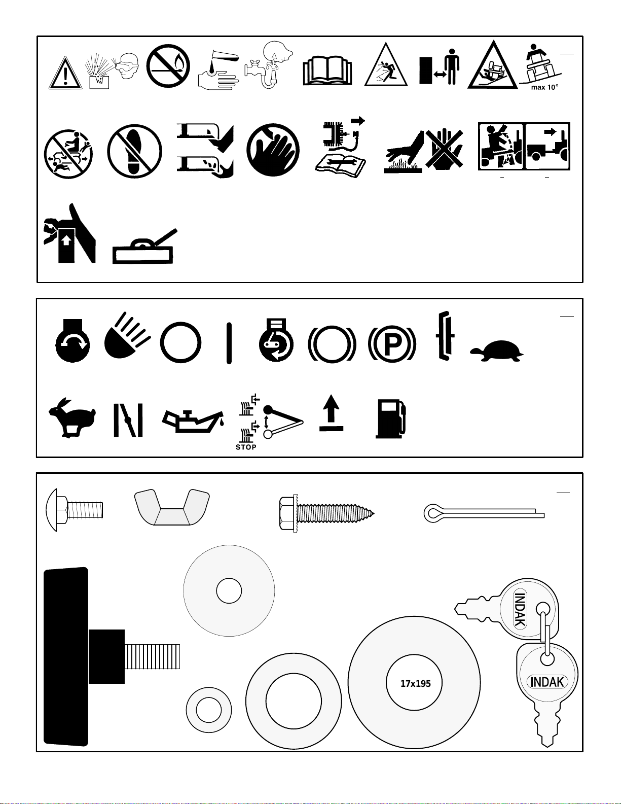
INTERNATIONAL PICTORIALS
IMPORTANT: The following pictorials are located on your unit or on literature supplied
with the product. Before you operate the
unit, learn and understand the purpose for
each pictorial.
NOTE: Illustrations and pictorials begin
on page 2.
Safety Warning Pictorials (Figure 23)
1 WARNING
2 Shield Eyes. Explosive Gases Can Cause
Blindness Or Injury.
3 No Sparks, Flames or Smoking.
4 Sulphuric Acid Can Cause Blindness Or
Severe Burns
5 Flush Eyes Immediately With Water. Get
Medical Help Fast.
6 IMPORTANT: Read Owner’s Manual
MODEL NO.: 405600x50A
SKU No.:
YEAR: XXXX
SERIAL NO.:
2600 min–1
183 kg
Manufactured in Lawrenceburg, TN 38464, U.S.A.
F–020727L
Before Operating This Machine.
7 WARNING: Thrown Objects. Keep
Bystanders Away. Read User Instructions
Before Operating This Machine.
8 WARNING: Do Not Use This Machine On
Slopes Greater Than 10 Degrees.
9 DANGER: Keep People, Especially
Children, Away From Unit.
10 DANGER: No Step.
11 DANGER: Keep Feet And Hands Away
From Rotating Blade.
12 DANGER: Keep Hands Away From
Rotating Blade.
13 DANGER: Disconnect Spark Plug Wire
Before Servicing Unit.
14 WARNING: Hot Surface.
15 WARNING: Use Caution When Connecting
Or Disconnecting Accessories.
16 WARNING: Crushed Fingers.
Declared vibration emission values in accordance with Directive 98/37/EC.
Vibration Emission according to BS EN 1032: Seat 0,89
Right Running Board 2,37 m/s
Vibration Emission according to BS EN 1033: Steering Wheel 1,03
Values determined with operator in operating position when the machine was
operated stationary on a concrete surface at 2600 min–1.
Declared airborne noise emissions in accordance with Directive 2000/14/EC,
Annex VIII.
Sound Pressure Level at operator position 82 dB.
Values determined at ear according to the specifications of EN ISO 11201.
5
17 IMPORTANT: Follow Instructions In
Owner’s Manual To Level The Deck.
Control And Operating Pictorials
(Figure 24)
1 Engine Start
2 Lights
3 Engine Run
4 Engine Stop
5 Engine Run
6 Brake
7 Parking Brake
8 Clutch
9 Slow
10 Fast
11 Choke
12 Oil
13 Blade Rotation Control
14 Raise
15 Fuel
2
, Left Running Board 1,24 m/s2
m/s2,
m/s
2
Page 6

OWNER’S INFORMATION
Know your product: If you understand the unit
and how the unit operates, you will get the best
performance. As you read this manual, compare
the illustrations to the unit. Learn the location
and the function of the controls. To help prevent
an accident, follow the operating instructions
and the safety rules. Keep this manual for future
reference.
WARNING: Look for this symbol to indicate
important safety precautions. This symbol
indicates: “Attention! Become Alert! Your
Safety Is At Risk.”
Responsibility Of The Owner
WARNING: This cutting machine is
capable of amputating hands and
feet and throwing objects. Failure
to observe the following safety instructions
could result in serious injury or death to
the operator or bystanders.
The responsibility of the owner is to
follow the instructions below.
SAFE OPERATION PRACTICES
For Ride–On (Riding)
Rotary Mower Machines
Training
1. Read the instructions carefully. Be familiar
with the controls and the proper use of the
equipment.
2. Never allow children or people unfamiliar
with these instructions to use the mower.
Local regulations may restrict the age of
the operator.
3. Never mow while people, especially
children, or pets are nearby.
4. Keep in mind that the operator or user is
responsible for accidents or hazards occurring to other people or their property.
5. Do not carry passengers.
6. All drivers should seek and obtain professional and practical instruction. Such
instruction should emphasize:
a. the need for care and concentration
when working with ride–on machines;
b. control of a ride–on machine sliding
on a slope will not be regained by the
application of the brake. The main
reasons for loss of control are:
insufficient wheel grip;
being driven too fast;
inadequate braking
the type of machine is unsuitable
for its task;
lack of awareness of the effect of
ground conditions, especially
slopes;
incorrect hitching and load dis-
tribution.
Preparation
1. While mowing, always wear substantial
footwear and long trousers. Do not operate
the equipment when barefoot or wearing
open sandals.
F–020727L
2. Thoroughly inspect the area where the
equipment is to be used and remove all objects which may be thrown by the machine.
3. WARNING – Petrol is highly flammable.
a. Store fuel in containers specifically de-
signed for this purpose.
b. Refuel outdoors only and do not
smoke while refuelling.
c. Add fuel before starting the engine.
Never remove the cap of the fuel tank
or add petrol while the engine is running or when the engine is hot.
d. If petrol is spilled, do not attempt to
start the engine but move the machine
away from the area of spillage and
avoid creating any source of ignition
until petrol vapours have dissipated.
e. Replace all fuel tanks and container
caps securely.
4. Replace faulty silencers.
5. Before using, always visually inspect to see
that the blades, blade bolts and cutter assembly are not worn or damaged. Replace
worn or damaged blades and bolts in sets
to preserve balance.
6. On multi–blade machines, take care as ro-
tating one blade can cause other blades to
rotate.
Operation
1. Do not operate the engine in a confined
space where dangerous carbon monoxide
fumes can collect.
2. Mow only in daylight or in good artificial
light.
3. Before attempting to start the engine, disengage all blade attachment clutches and
shift into neutral.
4. Do not use on slopes of more than 10 degrees.
5. Remember there is no such thing as a
“safe” slope. Travel on grass slopes requires particular care. To guard against
overturning:
a. do not stop or start suddenly when
going up or downhill;
b. engage clutch slowly, always keep
machine in gear, especially when travelling downhill;
c. machine speeds should be kept low
on slopes and during tight turns;
d. stay alert for humps and hollows and
other hidden hazards;
e. never mow across the face of the
slope, unless the mower is designed
for this purpose.
6. Use care when pulling loads or using heavy
equipment.
a. Use only approved drawbar hitch
points.
b. Limit loads to those you can safely
control.
c. Do not turn sharply. Use care when
reversing.
d. Use counterweight(s) or wheel
weights when suggested in the Instruction Book.
7. Watch out for traffic when crossing or near
roadways.
8. Stop the blades rotating before crossing
surfaces other than grass.
9. When using any attachments, never direct
discharge of material toward bystanders
6
GB
nor allow anyone near the machine while in
operation.
10. Never operate the mower with defective
guards or shields, or without safety protective devices in place.
11. Do not change the engine governor settings or overspeed the engine. Operating
an engine at excessive speed may increase the hazard of personal injury.
12. Before leaving the operator’s position
a. disengage the power take–off and
lower the attachments;
b. change into neutral and set the park-
ing brake;
c. stop the engine and remove the key.
13. Disengage drive to attachments, stop the
engine, and disconnect the spark plug
wire(s) or remove the ignition key
a. before cleaning blockages or unclog-
ging chute;
b. before checking, cleaning or working
on the mower;
c. after striking a foreign object. Inspect
the mower for damage and make repairs before restarting and operating
the equipment;
d. if the machine starts to vibrate abnor-
mally (check immediately).
14. Disengage drive to attachments when
transporting or not in use.
15. Stop the engine and disengage drive to attachment
a. before refuelling;
b. before removing the grass catcher;
c. before making height adjustment un-
less adjustment can be made from the
operator’s position.
16. Reduce the throttle setting during engine
run–out and, if the engine is provided with a
shut–off valve, turn the fuel off at the conclusion of mowing.
17. Before and when backing, look behind and
down for small children.
18. Use extra care when approaching blind
corners, shrubs, trees or other objects that
may obscure vision.
Maintenance and Storage
1. On multi–blade machines, take care as ro-
tating one blade can cause other blades to
rotate.
2. When machine is to be parked, stored or
left unattended, lower the cutting means
unless a positive mechanical lock is used.
3. Keep all nuts, bolts, and screws tight to be
sure the equipment is in safe working
condition.
4. Never store the equipment with petrol in the
tank inside a building where fumes may
reach an open flame or spark.
5. Allow the engine to cool before storing in
any enclosure.
6. To reduce the fire hazard, keep the engine,
silencer, battery compartment and petrol
storage area free of grass, leaves, or excessive grease.
7. Check the grass catcher frequently for
wear or deterioration.
8. Replace worn or damaged parts for safety.
9. If the fuel tank has to be drained, this
should be done outdoors.
Page 7
ASSEMBLY
f
All fasteners are in the parts bag. Do not discard
any parts or material until the unit is assembled.
WARNING: Before doing any assembly or maintenance to the
mower, remove the wire from the
spark plug.
NOTE: In this instruction book, left and right
describe the location of a part with the operator on the seat.
NOTE: Illustrations and pictorials begin on
page 2.
NOTE: To assemble the following loose
parts, use the fasteners shown at full size in
Figure 25.
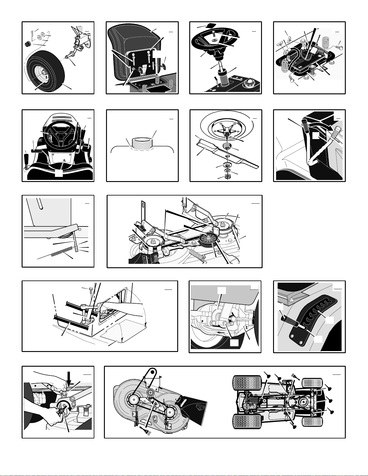
How To Install The Front Wheels
(Figure 1)
Use a knife and cut the four sides of the container. Install the front wheels (1) in the con-
tainer.
NOTE: Use a piece of wood about 4 feet (1.25
meters) long to raise the front of the tractor.
If a piece of wood cannot be found, get
another person to help lift the tractor. Be
careful, do not let the tractor fall.
1. Raise the front of the tractor. Set a support
(block of wood) under the tractor.
2. Make sure the valve stem (2) is to the out-
side of the tractor. Slide the front wheel (1)
on the spindle (3).
3. Fasten each front wheel (1) with washer (4)
and cotter pin (5). Bend the ends of the
cotter pin (5) appart to keep the front wheel
(1) on the spindle (3).
4. After the front wheels (1) are installed, lift
the tractor from the support. Roll the tractor
off of the container.
5. If your tractor has hub caps (6), install the
hub caps (6). Make sure the washers (4)
hold the hub caps (6) in place.
Check The Tyres
Check the air pressure in the tyres. Tyres with
too much air pressure will cause the unit to ride
rough. Also, the wrong air pressure will keep the
mower housing from cutting level. The correct
air pressure is: Front Tyres 0,97 BAR (14 PSI),
Rear Tyres 0,69 BAR (10 PSI). The tyres were
over inflated for shipment.
How To Install The Seat (Figure 2)
1. Carefully remove the plastic bag from the
seat (1).
2. Align the holes in the seat hinge (2) to the
holes in the seat (1). Fasten the seat (1) to
the seat hinge (2) with the fasteners (4) and
(5).
3. Check the operating position of the seat (1).
If the seat (1) needs to be adjusted, loosen
the two wing bolts (5). Slide the seat (1) forward or backward along the seat adjusting
holes (3). Tighten the wing bolts (5).
How To Assemble The Steering Wheel
(Figure 3)
1. Make sure the front wheels point forward.
2. Slide the cover (3) over the steering post
(2). Make sure the collar of the cover (3) is
on top.
3. Slide the steering wheel (1) onto the steer-
ing post (2).
4. Attach the steering wheel (1) to the steer-
ing post (2) with screw (4) and washer (6).
5. Some models have an optional insert (7) in
the parts bag. Attach the insert (7) to the
centre of the steering wheel (1).
Maintenance Free Battery (Figure 4)
IMPORTANT: Before you attach the battery
cables to the battery, check the battery date.
The battery date tells if the battery must be
charged.
1. Check the top of the battery (1) for the loca-
tion of the battery date.
2. If the battery (1) is put into service before
the , the battery cables can be attached without charging the battery (1). See “How To
Install The Battery Cables”.
3. If the battery (1) is put into service after the ,
the battery (1) must be charged. See “How
To Charge The Maintenance Free Battery”.
GB
2. Remove the protective caps from the battery
terminals.
3. Use a 12 volt battery charger to charge the
battery (1). Charge at a rate of 6 amperes
for one hour. If you do not have a battery
charger, have an authorized service centre
charge the battery.
4. Install the battery (1) and battery tray (3).
Make sure the positive (+) terminal (4) is on
the left side.
How To Install The Battery Cables
(Figure 4)
WARNING: To prevent sparks, fasten
the red cable to the positive (+) terminal before you connect the black
cable.
1. Remove the protective caps from the battery
terminals.
2. Slide the terminal cover (2) onto the red
cable (5). Fasten the red cable (5) to the
positive (+) terminal (4) with the fasteners
(6) and (7).
3. Fasten the black cable 8 to the negative (–)
terminal with the fasteners (6) and (7).
How To Prepare The Engine
NOTE: The engine was shipped from the factory filled with oil. Check the level of the oil.
Add oil as needed.
See the engine manufacturer’s instructions for
the type of petrol and oil to use. Before you use
the unit, read the information on safety, operation, maintenance, and storage.
WARNING: Follow the engine manufacturer’s instructions for the type o
petrol and oil to use. Always use a
safety petrol container. Do not smoke when
adding petrol to the engine. When inside an
enclosure, do not fill with petrol. Before you
add petrol, stop the engine. Let the engine
cool for several minutes.
Important! Before You Start Mowing
Check The Level Of The Mower
Housing
Make sure the level of cut is still correct. After
you mow a short distance, look at the area that
was cut. If the mower housing does not cut level,
see the instructions on “How To Level The
Mower Housing” in the Maintenance section of
this instruction book.
F–020727L
How To Charge The Battery (Figure 4)
WARNING: When you charge the
battery, do not smoke. Keep the bat-
tery away from any sparks. The
fumes from the battery acid can cause an
explosion.
1. Remove the battery (1) and battery tray (3).
7
Check the engine oil.
Fill the fuel tank with petrol.
Check the level of the mower hous-
ing.
Check the air pressure of the tyres.
Attach the battery cables.
Page 8
OPERATION
NOTE: Illustrations and pictorials begin on
page 2.
Location Of Controls (Figure 5)
Blade Rotation Control (1): Use the blade rota-
tion control to start and stop the rotation of the
blade.
Brake Pedal (2): Use the brake pedal to quickly
stop.
Headlight Switch (3): The headlight switch is
the first part of the ignition switch. To use the
lights with the engine running, turn the key to the
position for the lights.
Ignition Switch (3): Use the ignition switch to
start and stop the engine.
Speed Control Pedal (4): Use the speed control pedal to change the speed and the direction
of the unit.
Lift Lever (5): Use the lift lever to change the
height of cut.
Parking Brake Lever (6): Use the parking brake
lever to engage the brake when you leave the
unit.
Throttle Control Lever (7): Use the throttle
control lever to increase or decrease the speed
of the engine.
Automatic Drive disconnect (8): use the automatic drive disconnect, located under the seat,
to disengage the transmission.
Attachments
This unit can use many different attachments.
This unit can pull attachments like a lawn
sweeper, a lawn aerator, or a hopper spreader.
This unit can not use attachments that engage
the ground like a plough, a disk harrow, or a
cultivator.
For trailer and pull–behind attachments, the
maximum weight is 113 kg (250 lbs.).
How To Use The Throttle Control
(Figure 5)
Use the throttle control (7) to increase or de-
crease the speed of the engine.
1. The FAST position is marked with a detent.
For normal operation and when using a
grass bagger, move the throttle control to the
FAST position. For maximum charging of the
battery and for a cooler running engine, operate the engine in the FAST position.
2. The engine governor is set at the factory for
maximum performance. Do not adjust the
governor to increase the speed of the engine.
How To Use The Blade Rotation Control
(Figure 5)
Use the blade rotation control (1) to engage
the blade(s).
1. Before you start the engine, make sure the
blade rotation control (1) is in the DISENGAGE position.
2. Move the blade rotation control (1) to the
ENGAGE position to rotate the blade(s).
F–020727L
NOTE: If the engine stops when you engage the blade(s), the seat switch is not
activated. Make sure you sit in the middle
of the seat.
3. Move the blade rotation control (1) to the
DISENGAGE position to stop the blade(s).
Before you leave the operator’s position,
make sure the blade(s) has stopped rotating.
4. Before you ride the unit across a sidewalk or
a road, move the blade rotation control (1)
to the DISENGAGE position.
WARNING: Always keep your
hands and feet away from the
blade, deflector opening, and the
mower housing when the engine runs.
How To Use The Speed Control Pedal
(Figure 5)
The drive system uses a Hydrostatic Automatic
Drive transmission. The Hydrostatic transmission is very easy to operate. This type of
drive system does not require a shift lever or a
clutch pedal.
The speed and direction of travel is controlled by
a single speed control pedal (4) operated with
your right foot. Do not use the left brake pedal in
normal operation. Only use the left brake pedal
to quickly stop in an emergency.
How To Drive Forward
1. (Figure 20) The automatic drive disconnect (1) must be in the DRIVE position (2).
2. Slowly release your left foot from the brake
pedal.
3. Move the throttle control to the FAST position.
4. (Figure 19) Slowly push the speed control
pedal (1) forward (4) to the desired speed.
5. To increase forward speed, slowly move the
speed control pedal (1) forward. To reduce
forward speed, slowly release the speed
control pedal (1) until the unit slows to the
desired speed.
How To Drive In Reverse
1. Look to the rear.
2. Slowly push the speed control pedal (1) to
the REVERSE position (2).
How To Change Directions
CAUTION: To change directions, do not use
the left brake pedal. Use only the speed control pedal.
1. Slowly remove your foot from the speed
control pedal (1). The speed control pedal
(1) will automatically return to the NEUTRAL
position (3).
2. When the unit stops, slowly move the speed
control pedal (1) to the desired direction.
How To Disconnect The Transmission
(Figure 20)
To push the unit, use the automatic drive disconnect (1) to release the transmission. The
automatic drive disconnect (1) is under the
seat.
1. The engine must be off.
2. Raise the seat. The automatic drive dis-
connect (1) is under the seat.
8
GB
3. Move and latch the automatic drive disconnect (1) in the PUSH position (3). The
transmission is now released and the unit
can be pushed.
NOTE: In cold weather, the heavy viscosity oil in the transmission will make the
unit difficult to push.
4. To engage the transmission, unlatch the automatic drive disconnect (1). The trans-
mission is now connected and ready to
operate.
How To Use The Parking Brake
(Figure 5)
1. Completely push the brake pedal (2) for-
ward.
2. Lift the parking brake lever (6).
3. Remove your foot from the brake pedal (2)
and then release the parking brake lever
(6). Make sure the parking brake will hold the
unit.
4. To release the parking brake (6), completely
push the brake pedal (2) forward. The parking brake will automatically release.
WARNING: Before you leave the
operator’s position, set the parking
brake. Move the blade rotation control to the DISENGAGE position. Stop the
engine and remove the ignition key.
How To Change The Cutting Height
(Figure 5)
To change the cutting height, raise or lower the
lift lever (5) as follows.
1. Move the lift lever (5) forward to lower the
mower housing and back to raise the mower
housing.
2. When you ride on a sidewalk or road, move
the lift lever (5) to the highest position and
move the blade rotation control to the DISENGAGE position.
How To Stop The Unit (Figure 5)
1. Slowly remove your foot from the speed
control pedal (4). The speed control pedal
(1) will automatically return to the NEUTRAL
position and the unit will stop.
2. Move the blade rotation control (1) to the
DISENGAGE position.
3. Set the parking brake (6).
WARNING: Make sure the parking
brake will hold the unit.
4. Move the throttle control (7) to the SLOW
position.
5. To stop the engine, turn the ignition key (3)
to the OFF position. Remove the key.
How To Transport The Unit
To transport the unit, follow the steps below.
1. Move the blade rotation control to the DISENGAGE position.
2. Raise the lift lever to the highest position.
3. Move the throttle control to a position between SLOW and FAST.
Page 9
4. Slowly push the speed control pedal forward
to the desired speed.
How To Operate With The Mower
Housing
IMPORTANT: When you operate with the
mower housing, always operate with the
throttle control in the FAST position.
1. Start the engine.
2. Move the lift lever to a height of cut position.
In high or thick grass, cut the grass in the
highest position first and then lower the
mower housing to a lower position.
3. Move the throttle control to the SLOW position.
4. Slowly move the blade rotation control to the
ENGAGE position.
5. Move the throttle control to the FAST position.
6. Slowly push the speed control pedal to the
desired speed.
NOTE: When you mow in heavy grass or
mow with a bagger, use a slow forward
speed.
7. Make sure the level of cut is still correct.
After you mow a short distance, look at the
area that was cut. If the mower housing does
not cut level, see the instructions on “How To
Level The Mower Housing” in the Maintenance section.
WARNING: For better control of the
unit, select a safe speed.
How To Operate On Hills
WARNING: Do not ride up or down
slopes that are too steep to back
straight up. Never ride the unit
across a slope.
1. Control the speed only with the speed control
pedal. Do not use the brake pedal on a hill.
2. To help prevent an accident, slowly move the
speed control pedal. Avoid sudden turns or
changes in speed.
3. To reduce forward speed when going down a
hill, slowly release the speed control pedal
until the unit slows to the desired speed.
How To Stop On a Hill
1. Avoid stopping on a hill. If you must quickly
stop in an emergency, remove your right foot
from the speed control pedal and quickly depress the left brake pedal.
2. Set the parking brake.
3. Before you dismount from the seat, move the
throttle control to the SLOW position, move
the blade rotation control to the DISENGAGED position, turn off the engine and set
the parking brake.
How To Start Operation On A Hill
1. Start the engine
2. Move the blade rotation control to the ENGAGED position.
F–020727L
3. Move the throttle control to the FAST position.
4. Depress the brake pedal and release the
parking brake. As you release the parking
brake, push the speed control pedal to the
desired speed.
Slowly push the speed control
pedal as you release the parking
brake. The parking brake must be
disengaged before the speed control pedal
is able to engage the transmission.
Before Starting The Engine
Check the oil
NOTE: The engine was shipped from the factory filled with oil. Check the level of the oil.
Add oil as needed. See the engine manufacturer’s instructions for the type of petrol and
oil to use.
1. Make sure the unit is level.
NOTE: Do not check the level of the oil
while the engine runs.
2. Check the oil. Follow the procedure in the
engine manufacturer’s instructions.
3. If necessary, add oil until the oil reaches the
FULL mark on the dipstick. The quantity of oil
needed from ADD to FULL is shown on the
dipstick. Do not add too much oil.
Add Petrol
WARNING: Always use a safety
petrol container. Do not smoke
when adding petrol to the fuel tank.
Do not add petrol when you are inside an
enclosure. Before you add petrol, stop the
engine and let the engine cool for several
minutes.
(Figure 6) Fill the fuel tank (1) to the FULL (2)
position with regular unleaded petrol. Do not use
premium unleaded petrol. Make sure the petrol
is fresh and clean. Leaded petrol will increase
deposits and shorten the life of the valves.
How To Start The Engine
WARNING: The electrical system
has an operator presence system
that includes a sensor switch for
the seat. These components tell the
electrical system if the operator is sitting
on the seat. This system will stop the
engine when the operator leaves the seat if
the blade rotation control is engaged or if
the transmission is engaged. For your
protection, always make sure this system
operates correctly.
NOTE: The engine will not start unless you
depress the brake pedal or engage the parking brake and move the blade rotation control to the DISENGAGE position.
1. Push the brake pedal completely forward.
Keep your foot on the pedal.
2. Make sure the blade rotation control is in the
DISENGAGE position.
3. Move the throttle control completely forward
to the CHOKE or FAST position. Some mo-
9
GB
dels have a separate choke knob. Pull the
choke knob to the full CHOKE position.
4. Turn the ignition key to the START position.
NOTE: If the engine does not start after
four or five tries, move the throttle control
to the FAST position. Again try to start the
engine. If the engine will not start, see the
TROUBLE SHOOTING CHART.
5. Slowly move the throttle control to the SLOW
position.
6. To start a hot engine, move the throttle control to a position between FAST and SLOW.
Mowing And Bagging Tips
1. For a lawn to look better, check the cutting
level of the mower housing. See “How To
Level The Mower Housing” in the Maintenance section.
2. For the mower housing to cut level, make
sure the tyres have the correct amount of air
pressure.
3. Every time you use the unit, check the blade.
If the blade is bent or damaged, immediately
replace the blade. Also, make sure the nut
for the blade is tight.
4. Keep the blade(s) sharpened. Worn blades
will cause the ends of the grass to turn
brown.
5. Do not cut or bag grass that is wet. Wet
grass will not discharge correctly. Let the
grass dry before cutting.
6. Use the left side of the mower housing to trim
near an object.
7. Discharge the cut grass onto the mowed
area. The result is a more even discharge of
cut grass.
8. When you mow large areas, start by turning
to the right so that the cut grass will discharge away from shrubs, fences, driveways,
etc. After one or two rounds, mow in the opposite direction making left turns until finished.
9. If the grass is very high, cut two times to decrease the load on the engine. First cut with
the mower housing in the highest position
and then lower the mower housing for the
second cut.
10.For better engine performance and an even
discharge of the cut grass, always operate
the engine with the throttle in FAST position.
11.When you use a bagger, operate the engine
with the throttle in FAST position and the
speed control pedal pushed 1/3 to 1/2 forward..
12.After each use, clean the bottom and top of
the mower housing for better performance.
Also, a clean mower housing will help prevent a fire.
MAINTENANCE
NOTE: Illustrations and pictorials begin on
page 2.
General Recommendations
1. The owner’s responsibility is to maintain this
product. This will extend the life of the product and is also necessary to maintain warranty coverage.
2. Check the spark plug, drive brake, lubricate
the unit, and clean the air filter once a year.
Page 10
3. Check the fasteners. Make sure all fasteners
are tight.
4. Follow the Maintenance section to keep the
unit in good operating condition.
WARNING: Before you make an inspection, adjustment, or repair to
the unit, disconnect the wire to the
spark plug. Remove the wire from the
spark plug to prevent the engine from
starting by accident.
NOTE: Torque is measured in foot pounds
(metric Nm). This measurement describes
how tight a nut or bolt must be. The torque is
measured with a torque wrench.
Inspect Blade (Figure 7)
WARNING: Before you inspect or
remove the blade, disconnect the
wire to the spark plug. If the blade
hits an object, stop the engine. Check the
unit for damage. The blade has sharp
edges. When you hold the blade, use
gloves or cloth material to protect your
hands.
If you keep the blade (1) sharp and inspect the
blade for damage, the blade will cut better and
be more safe to operate. Frequently check the
blade for excessive wear, cracks, or other damage. Frequently check the nut (3) that holds the
blade (1). Keep the nut (3) tight. If the blade hits
an object, stop the engine. Disconnect the wire
to the spark plug. See if the blade is bent or
damaged. Check the blade adapter (5) for damage. Before you operate the unit, replace damaged parts with original equipment parts. See
the authorized service centre in your area. Every
three years, have an authorized service person
inspect the blade or replace the old blade with
an original equipment part.
How To Remove And Install The Blade
(Figure 7)
1. Remove the mower housing. See the instructions on “How To Remove The Mower Housing”.
2. Use a piece of wood to keep the blade from
rotating.
3. Remove the nut (3) that holds the blade (1).
4. Check the blade (1) and the blade adapter
(5) according to the instructions for “Inspect
Blade”. Replace a badly worn or damaged
blade with an original equipment blade. See
an authorized service centre in your area.
5. Clean the top and bottom of the mower housing. Remove all the grass and debris.
6. Mount the blade (1) and blade adapter (5)
on the mandrel (6).
7. Mount the blade (1) so that the hi–lift edges
(7) are up. If the blade is upside down, the
blade will not cut correctly and can cause an
accident.
8. Fasten the blade (1) with the original
washers and nut (3). Make sure the outside
rim of the Belleville washer (2) is against
the blade (1).
F–020727L
WARNING: Always keep the nut (3)
tight that holds the blade (1). A
loose nut or blade can cause an
accident.
9. Tighten the nut (3) that holds the blade (1) to
a torque of 30 foot pounds (41,5 Nm).
10.Install the mower housing. See “How To Re-
move The Mower Housing”.
How To Adjust The Blade Rotation
Control
WARNING: To prevent an injury, the
blade rotation control must operate
correctly.
In normal usage, the blade rotation control will
not require an adjustment. However, if the cutting performance decreases or the quality of cut
is poor, make the following changes.
1. When you mow, make sure the throttle control in in the FAST position.
2. (Figure 8) Move the blade rotation control to
the DISENGAGE position (1).
3. Stop the engine. Disconnect the wire from
the spark plug.
4. Check the blade(s). Keep a sharp edge on
the blade(s). A blade that is not sharp will
cause the tips of the grass to become brown.
5. (Figure 9) Disconnect the blade drive
spring (2) from the blade control rod (1).
Move the blade drive spring (2) to the
middle hole (4). This will increase the tension on the mower drive belt.
6. Attach the wire to the spark plug. Mow for a
short distance and again check the quality of
cut. If necessary, move the blade drive
spring (2) to the bottom hole (5)
7. Again check the quality of cut. If the quality of
cut has not improved, replace the mower
drive belt. See “How To Replace The Mower
Drive Belt”. If the replacing the belt does not
correct the problem, take the unit to an authorized service centre.
8. Move the blade rotation control to the DISENGAGE position. Stop the engine.
9. (Figure 10) Check the operation of the blade
brake. Rotate the pulleys with your hand.
Make sure the brake pads (1) are pressed
tightly against the pulleys
WARNING: If the brake pads (1) do
not press tightly against the
pulleys, take the unit to an author-
ized service centre.
10.(Figure 8) Move the blade rotation control to
the ENGAGE position (2).
11. (Figure 10) Check the pads for the blade
brake (7). If the pads are excessively worn
or damaged, replace the brake pad assemblies. Correct replacement parts and assistance are available from an authorized
service centre.
12.Attach the wire to the spark plug. Mow for a
short distance and again check the operation
of the blade rotation control.
13.When you move the blade rotation control to
the DISENGAGE position, all movement will
stop within five seconds. If there is movement of the belt or the blades continue to rotate, engage and disengage the blade
rotation control five times to remove any ex-
10
GB
cess rubber from a new mower drive belt. If
you need assistance, take the unit to an
authorized service centre.
14.(Figure 9) If you replace the mower drive
belt, move the blade drive spring (2) to the
top hole (3).
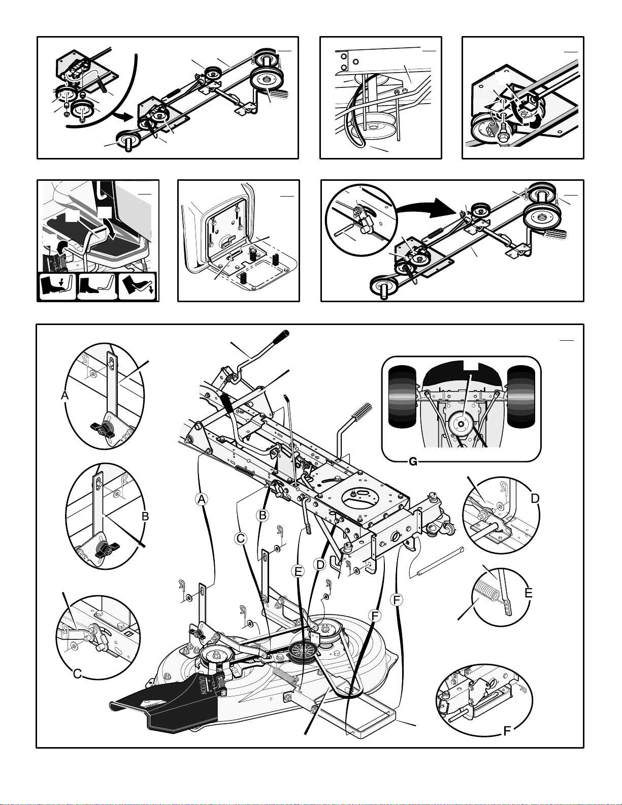
How To Check And Adjust The Motion
Drive Belt (Figure 18 and Figure 21)
If the motion drive belt is loose, the belt will slip
when; going up a hill, pulling a heavy load, or the
unit will not move forward.
IMPORTANT: Always operate with the engine
speed in the FAST position. If the engine
speed is in a slow or moderate position, the
engine and transmission can become too hot
and cause problems that are similar to a
loose motion drive belt.
WARNING: Before you make an inspection, adjustment, or repair to
the unit, disconnect the wire to the
spark plug. Remove the wire from the
spark plug to prevent the engine from
starting by accident.
1. (Figure 21) Check the routing of the motion
drive belt (6). Make sure the motion drive
belt (6) is installed correctly and is inside all
the belt guides (7).
2. (Figure 18) Disconnect the clutch link (1)
from the idler arm (2).
3. (Figure 21) Align the hole in the brake lever
(3) with the hole in the frame. Hold the brake
lever (3) in place with a 1/4 inch (6 mm) pin
or bolt (4).
4. (Figure 18) Rotate the clutch link (1) until
the mounting hole (5) in the clutch link (1)
is aligned with the mounting hole (5) in the
idler arm (2).
5. Connect the clutch link (1) to the idler arm
(2).
6. (Figure 21) Remove the 1/4 inch (6 mm)
pin or bolt (4).
7. If the belt still slips after the belt has been
adjusted, then the motion drive belt is worn
or damaged and must be replaced. See
“How To Replace The Motion Drive Belt”.
How To Check And Adjust The Drive
Brake (Figure 12 and 20)
(Figure 20) Set the parking brake. Move the au-
tomatic drive disconnect (1) to the PUSH
position (3). Push the unit. If the rear wheels
rotate, adjust or replace the brake pads.
Adjust the drive brake (4) as follows:
1. (Figure 12) The location of the drive brake
(4) is on the right side of the gearbox (5).
2. (Figure 20) Make sure the parking brake is
set and the automatic drive disconnect (1)
is in the PUSH position (3).
3. (Figure 12) Turn the hex nut (6) in a clockwise direction until the rear wheels do not
turn when the unit is pushed forward.
4. Release the parking brake and push the unit.
If the unit does not roll, turn the hex nut (6)
in a counter–clockwise direction until the unit
rolls.
5. Set the parking brake. Push the unit. If the
rear wheels do not turn, the drive brake (4)
is correctly adjusted. Release the parking
brake.
Page 11
WARNING: If you cannot correctly
adjust the drive brake, replace the
brake pads. Correct replacement
parts and assistance are available from an
authorized service centre.
How To Remove The Battery (Figure 4)
To charge or clean the battery (1), remove the
battery (1) from the unit as follows.
WARNING: To prevent sparks, dis-
connect the black battery cable (8)
from the negative (–) terminal before you disconnect the red cable (5).
WARNING: The battery contains
sulphuric acid which is harmful to
the skin, eyes and clothing. If the
acid gets on the body or clothing, wash
with water.
1. Disconnect the black cable (8) from the
negative (–) terminal.
2. Disconnect the red cable (5) from the posi-
tive (+) terminal (4).
3. Lift the battery tray (3) and the battery (1)
out of the unit.
How To Charge The Battery (Figure 4)
WARNING: When you charge the
battery, do not smoke. Keep the
battery away from any sparks. The
fumes from the battery acid can cause an
explosion.
1. Before you charge the battery (1), remove
the battery (1).
2. To charge the battery (1), use a 12 volt bat-
tery charger. Charge at a rate of 6 amperes
for 1 hour.
3. Install the battery (1).
WARNING: To prevent sparks,
fasten the red cable to the positive
(+) terminal before you connect the
black cable.
4. Fasten the red cable (5) to the positive (+)
terminal (4) with the fasteners as shown.
5. Fasten the black cable (8) to the negative
(–) terminal with the fasteners as shown.
How To Level The Mower Housing
(Figure 13 and Figure 14)
If the mower housing is level, the blade will cut
easier and the lawn will look better.
WARNING: Before you make an inspection, adjustment, or repair to
the unit, disconnect the wire to the
spark plug. Remove the spark plug wire to
prevent the engine from starting by accident
1. Make sure the unit is on a hard flat surface.
2. Check the air pressure in the tyres. If the air
pressure is incorrect, the mower housing will
not cut level. Make sure the tyres are inflated
to: Front Tyres 0,97 BAR (14 PSI), Rear
Tyres 0,69 BAR (10 PSI).
3. (Figure 13) Move the lift lever (1) to the
lowest cut position (2).
F–020727L
WARNING: The lifter lever (3) is
spring loaded. Make sure the lift
lever (3) is locked in the lowest cut
position (2).
4. (Figure 14) Loosen the left and right adjuster knobs (1). Push down on each side of
the mower housing. Make sure both sides of
the mower housing are setting on a flat surface. Also, make sure the lift links are loose
and can easily move up or down.
5. Push down on the lift links (2) and tighten
the left and right adjuster knobs (1). Make
sure the adjuster knobs (1) are tight. If
necessary, use a wrench to tighten the ad-
juster knobs (1).
6. (Figure 13) Raise the lift lever (1).
7. Mow for a short distance. If the height of cut
is not level, repeat the above steps.
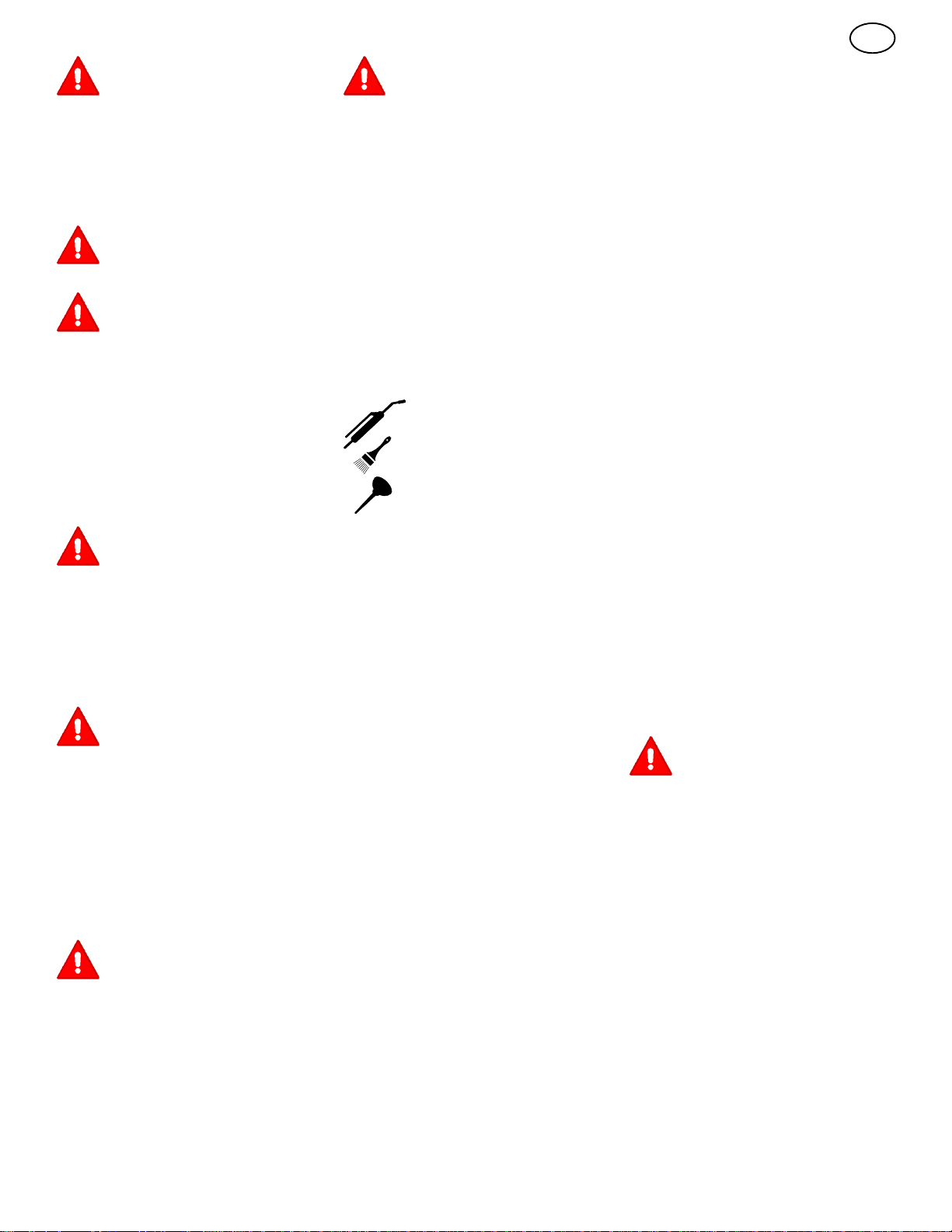
Where To Lubricate (Figure 15)
Models with grease fittings:
Lubricate with grease gun.
Apply grease with a brush to
the areas shown.
Lubricate the areas shown
with engine oil.
NOTE: Apply grease to the steering gear assembly.
CAUTION: If the unit is operated in dry areas
that have sand, use a dry graphite spray to
lubricate the unit.
Check The Tyres
Check the air pressure in the tyres. Tyres with
too much air pressure will cause the unit to ride
rough. Also, the wrong air pressure will keep the
mower housing from cutting level. The correct
air pressure is: Front Tyres 0,97 BAR (14 PSI),
Rear Tyres 0,69 BAR (10 PSI).
How To Replace The Motion Drive Belt
1. Remove the mower housing. See the instructions on “How To Remove The Mower Housing”.
2. (Figure 16) Remove the mid–idler pulley
(4).
3. Disconnect the idler spring (7).
4. Remove the idler pulley (8) and spacer (9).
5. Remove the V–ilder pulley (5) and spacer
(13).
6. Remove the motion drive belt (1) from the
drive pulley (6).
7. (Figure 17) To remove the motion drive belt
(1) from the stack pulley (2), pull the front
end of the belt under the stack pulley (2)
and then back between the stack pulley and
the steering plate (3).
8. (Figure 11) Remove the access panel (10).
9. Remove the two screws (11) that attach the
steering shaft assembly (12). Raise the
steering wheel and steering shaft assembly
(12). Pull the motion drive belt (1) under the
steering shaft assembly (12).
11
GB
10.Remove the motion drive belt (1). A correct
replacement part or assistance is available
from an Authorized Service Center in your
area.
11.To install the motion drive belt, reverse the
above steps.
12.(Figure 16) Check the routing of the motion
drive belt (1). Make sure the motion drive
belt is installed correctly on the idler pulleys.
13.Before you use the unit, check the adjustment of the clutch. See the instructions “How
To Check And Adjust The Clutch”.
14.Install the mower housing. See the instructions “How To Install The Mower Housing”.
How To Replace The Mower Drive Belt
(Figure 10)
1. Remove the mower housing. See the instructions on “How To Remove The Mower Housing”.
2. Pull the belt retainer (1) away from the idler
pulley (2) and remove the mower drive belt
(3).
3. Pull the belt retainer (4) away from the right
mandrel pulley (5) and remove the mower
drive belt (3).
4. Pull the belt retainer (4) away from the left
mandrel pulley (6) and remove the mower
drive belt (3). A correct replacement part or
assistance is available from an Authorized
Service Centre in your area.
5. To install the mower drive belt, reverse the
above steps.
How To Remove The Mower Housing
(Figure 22)
1. Move the blade rotation control (1) to the
DISENGAGE position.
2. Move the lift lever (2) to the level adjust-
ment position.
The lift lever is spring loaded. Make
sure the lift lever is locked in the
LEVEL ADJUSTMENT position.
3. Remove the hair pins and the washers from
the adjuster arms (3). See illustrations “C”
and “D”.
4. Remove the hair pins and washers from the
suspension links (4). See illustrations “A”
and “B”.
5. Disconnect the extension spring (5) from
the blade control rod (6). See illustration
“E”.
6. Disconnect the front hanger (9) from the
axle support. See illustration “F”.
7. Remove the mower drive belt (7) from the
stack pulley (8).
8. Pull the mower housing away from the right
side of the unit.
9. To install the mower housing, reverse the
above steps.
How To Replace The Fuse
If the fuse is blown, the engine will not start.
Remove the fuse and replace with a 15 amp.
automotive fuse.
Page 12

Storage (over 30 days)
At the end of each year, prepare the unit for storage as follows.
1. Drain the fuel from the carburettor and the
fuel tank. Change the engine oil. See the engine manufacturer’s instructions.
2. Clean the entyre unit.
3. Charge the battery.
GB
How To Order Replacement Parts
The replacement parts are shown either on the
back pages of this Instruction Book or in a separate Parts List Book.
Use only manufacturer’s authorized or approved
replacement parts. The letter placed on the end
of the part number denotes the type of finish for
the part, C for chrome, Z for zinc, a PA for purchased assembly. It is important that you include
this when ordering a part. Do not use attachments or accessories not specifically recommended for this unit. In order to obtain proper
replacement parts you must supply the model
number of your mower (see nameplate).
Replacement parts, except for the engine, transmission, transaxle or differential, are available
from the store where the mower was purchased
or a service shop recommended by the store.
If you are unable to obtain parts or service in the
manner outlined above, then contact:
Murray, Inc., International Sales, PO Box 268,
Brentwood, TN 37024, USA. Fax (615)
373–6633. Collect telephone calls will not be
accepted.
Replacement parts for the engine, transaxle, or
transmission, are available from the manufacturer’s authorized service centre found in the
commercial pages of the telephone directory.
Also, see the individual engine or transmission
warranties to order replacement parts.
When ordering the following information is required:
(1) The Model Number
(2) Serial Number
(3) Part Number
(4) Quantity
F–020727L
12
Page 13

TROUBLE SHOOTING CHART
PROBLEM: The engine will not start.
1. Follow the steps, “How To Start The Engine”
in this book.
2. Electric–Start Models: Clean the battery terminals. Tighten the cables.
3. Check for a loose wire. Tighten the limit
switches. (See the wiring diagram.)
4. Drain the fuel tank. Clean the fuel line. Replace the fuel filter.
5. Remove the spark plug(s). Move the throttle
to the SLOW position. Turn the ignition key to
the ON position. Try to start the engine several times. Install the spark plug.
6. Replace the spark plug.
7. Adjust the carburettor.
PROBLEM: The engine will not turn
over.
1. Follow the steps, “How To Start The Engine”
in this book.
2. Electric–Start Models: Charge the battery.
3. Replace the fuse.
4. Check the wiring harness for damage or a
loose connection. Repair the damaged wire.
5. Electric–Start Models: replace the solenoid.
Recoil–Start Models: replace the module.
PROBLEM: The engine is difficult to
start.
1. Adjust the carburettor.
2. Replace the spark plug.
3. Replace the fuel filter.
PROBLEM: The engine does not run
smooth or has a loss of power.
1. Check the oil.
2. Clean the air filter.
3. Clean the air screen.
4. Replace the spark plug.
5. The engine is working too hard. Use a lower
gear.
6. Adjust the carburettor.
7. Replace the fuel filter.
PROBLEM: The engine does not run
smooth at fast speed.
1. Replace the spark plug.
2. Adjust the throttle control.
3. Clean the air filter.
4. Replace the fuel filter.
PROBLEM: The engine stops when the
blades are engaged.
1. Check the wiring harness for damage or a
loose connection. Repair the damaged wire.
2. Grass bag must be installed (applies only to
model with rear discharge grass bag).
PROBLEM: On slopes, the engine
stops.
1. Mow up and down slopes. Never mow
across a slope.
PROBLEM: The engine will not idle.
1. Replace the spark plug.
2. Clean the air filter.
3. Adjust the carburettor.
4. Adjust the throttle control.
5. Drain the fuel tank. Clean the fuel line. Replace the fuel filter.
PROBLEM: A hot engine causes a decrease in power.
1. Clean the air screen.
2. Check the oil.
3. Adjust the carburettor.
4. Replace the fuel filter.
PROBLEM: Excessive vibration.
1. Replace the blade.
2. Check for loose engine bolts.
3. Decrease the air pressure in the tyres.
4. Adjust the carburettor.
5. Check for a damaged belt or damaged
pulley. Replace the damaged parts.
PROBLEM: The grass does not discharge correctly.
1. Stop the engine. Clean the mower housing.
2. Raise the height of cut.
3. Replace or sharpen the blade(s).
4. Move the shift lever to a slower speed.
GB
5. Move the throttle control to the FAST position.
6. Replace the spring for the blade idler.
7. Clean the extension tube and the connector
tube (applies only to model with rear discharge grass bag).
PROBLEM: The mower housing does
not cut level.
1. Check the air pressure in the tyres.
2. Adjust the level of the mower housing.
3. Check the front axle. If the front axle does
not freely pivot, loosen the axle bolt(s).
PROBLEM: The mower blades will not
rotate.
1. Check the mower drive belt. Make sure the
belt is installed correctly.
2. Replace the mower drive belt.
PROBLEM: The unit will not move when
the brake is released and the speed
control pedal is depressed.
1. Check the motion drive belt. Make sure the
belt is installed correctly.
2. Adjust the clutch.
3. Replace the motion drive belt.
4. Release the Automatic Drive Disconnect
under the seat.
PROBLEM: The unit moves slower or
stops when the speed control pedal is
depressed.
1. Adjust the clutch.
2. Replace the motion drive belt.
PROBLEM: When the brake pedal is released, belt noise can be heard.
1. Temporary belt noise does not change the
operation of the unit. If belt noise is continuous, check the routing of the belt. Make sure
the belt is inside all belt guides.
2. If the noise is continuous, adjust the clutch.
PROBLEM: The rear wheels spin over
uneven terrain.
1. Check the front axle. If the front axle does
not freely pivot, loosen the axle bolt(s).
F–020727L
13
Page 14
INDICE
SIMBOLI INTERNAZIONALI 32
INFORMAZIONI PER IL PROPRIETARIO 33
PROCEDURE PER UN USO SICURO 33
MONTAGGIO 34
USO 35
MANUTENZIONE 37
SOLUZIONE DI PROBLEMI 40
MURRAY, INC.
GARANZIA LIMITATA DI DUE ANNI
Murray, Inc. garantisce all’acquirente originale
che questa unità sarà libera da difetti in materiali
e lavorazione in condizioni d’uso e manutenzione normali per un periodo di due (2) anni dalla
data d’acquisto; tuttavia, questa garanzia non
copre motori, accessori (come spartineve a turbina, lame da neve, insaccatrici di erba e aratri),
trasmissioni, batterie e parti soggette a normale
usura (tranne per quanto segue) o gruppi cambio differenziale posteriore in quanto le aziende
che fabbricano queste parti forniscono le proprie
garanzie e manutenzione attraverso le sedi autorizzate. Per ulteriori informazioni, vedere le
garanzie che coprono queste particolari parti. Se
non si è sicuri se l’unità contiene o è dotata di
una o più di queste parti, consultare il rivenditore
prima dell’acquisto. Secondo questi termini e
condizioni indicati in questa garanzia limitata
ripareremo o sostituiremo, a nostro giudizio,
senza alcun addebito per l’originale acquirente
qualsiasi parte coperta da questa garanzia limitata durante il periodo applicabile.
Se la batteria risulta difettosa entro novanta (90)
giorni dalla data di acquisto, la sostituiremo gratuitamente. Se la batteria risulta difettosa dopo
(90) giorni ma entro centoventi (120) giorni dalla
data di acquisto, la sostituiremo con un addebito
di metà (1/2) del prezzo della batteria al momento del rinvio.
Si definiscono parti soggette a normale usura:
cinghie, lame, adattatori di lama, pneumatici, fari
e copri sedili. Queste parti sono garantite prive
di difetti in materiali e lavorazione al momento
della consegna con il prodotto. Qualsiasi richiesta di riparazione o sostituzione delle parti soggette a normale usura deve essere inoltrata
entro trenta (30) giorni dalla data di acquisto.
Nessuna richiesta originata da danni causati da
uso non conforme alle istruzioni, o maltrattamento del materiale sarà onorata.
Questa garanzia limitata di due (2) anni della
Murray, Inc. è l’unico rimedio dell’acquirente;
tuttavia, questa garanzia è nulla o non applicabile a unità che siano state manomesse, modificate, usate non conformemente alle istruzioni,
maltrattate o usate per noleggi o altri usi commerciali e/o professionali (non residenziali). La
garanzia non copre minori regolazioni meccaniche non dovute a difetti in materiali o lavorazione. Per assistenza nell’effettuare questo tipo di
regolazione, consultare il libretto di istruzioni.
I
Per inoltrare una richiesta secondo questa garanzia limitata di due (2) anni della Murray,
Inc., rinviare l’unità (oppure, dietro previa auto-
rizzazione, la parte difettosa) insieme ad una
prova di acquisto ad un centro di assistenza tecnica autorizzato. Per individuare il centro di assistenza tecnica autorizzato più vicino, chiamare il
distributore parti centrale della zona indicato
nell’elenco fornito con l’unità, o controllare le
pagine gialle dell’elenco telefonico locale. Se si
rinvia l’intera unità, ripareremo l’unità. Se autorizziamo il rinvio della parte difettosa solamente,
sostituiremo o ripareremo la parte. In caso di un
difetto nella trasmissione o nel differenziale (distinto dal gruppo cambio differenziale posteriore), si deve rinviare l’intera trasmissione o
differenziale poiché essi non includono parti so-
stituibili dall’utente.
Questa garanzia limitata di due (2) anni della
Murray, Inc., dà all’acquirente diritti legali speci-
fici, ma possono esservene altri a seconda del
luogo di residenza. Questa garanzia limitata è
a sostituzione di tutte le altre garanzia
espresse e implicite fra cui la garanzia implicita di commerciabilità e la garanzia di idoneità per un uso particolare. Per ulteriori
informazioni su questa garanzia scritta o su come ottenere assistenza, scrivere al seguente
indirizzo:
Murray, Inc., International Sales, PO Box 268,
Brentwood, TN 37024, USA. Fax (615)
373–6633.
SIMBOLI INTERNAZIONALI
IMPORTANTE: i seguenti simboli si trovano
sull’unità o sulla documentazione che correda il prodotto. Prima di usare l’unità apprendere e capire lo scopo di ogni simbolo.
NOTA: le illustrazioni e i simboli
iniziano a pagina 2.
Simboli di sicurezza (Figura 23)
1 Attenzione
2 Riparare gli occhi. Gas esplosivi possono
causare cecità o lesioni.
3 Tenere al riparo da scintille, fiamme, non
fumare.
4 L’acido solforico può causare cecità o
ustioni gravi.
5 Lavare gli occhi immediatamente con
acqua. Consultare prontamente il medico.
6 IMPORTANTE: leggere il manuale d’uso
MODEL NO.: 405600x50A
SKU No.:
YEAR: XXXX
SERIAL NO.:
2600 min–1
183 kg
Manufactured in Lawrenceburg, TN 38464, U.S.A.
F–020727L
prima di usare questa macchina.
7 ATTENZIONE: oggetti lanciati. Tenere alla
larga i presenti. Leggere le istruzioni d’uso
prima di usare questa macchina.
8 ATTENZIONE: non usare questa macchina
su pendenze superiori a 10 gradi.
9 PERICOLO: tenere lontano i presenti,
specialmente bambini dall’unità.
10 PERICOLO: senza gradino.
11 PERICOLO: tenere lontano mani e piedi
dalle lame in movimento.
12 PERICOLO: tenere lontano le mani dalle
lame in movimento.
13 PERICOLO: scollegare il filo della candela
di accensione prima di eseguire la
manutenzione dell’unità.
14 ATTENZIONE: superficie calda.
15 ATTENZIONE: fare attenzione quando si
collegano o scollegano accessori.
16 ATTENZIONE: Fare attenzione a non
schiacciarsi le dita.
Valori dichiarati di emissione di vibrazioni in conformità con la direttiva 98/37/CE.
Emissione di vibrazioni: in conformità con la normativa BS EN 1032:
sedile 0,89
Emissione di vibrazioni: in conformità con la normativa BS EN 1033:
Volante 1,03
Valori determinati con l’operatore nella posizione d’uso e la macchina in funzione,
stazionaria su una superficie di cemento a 2600 min–1.
Emissioni dichiarate di rumore nell’aria in conformità con la direttiva 2000/14/CE,
Allegato VIII.
Livelli di pressione acustica alla posizione dell’operatore 82
Valori determinati alle orecchie dell’operatore secondo le specifiche della
norma EN ISO 11201.
m/s2, Asse destro 2,37 m/s2, asse sinistro 1,24 m/s2
2
m/s
32
17 IMPORTANTE: seguire le istruzioni nel
manuale d’uso per mettere in piano
l’alloggiamento del tagliaerba.
Simboli dei comandi e d’uso (Figura 24)
1 Avvio del motore
2 Fari
3 Motore in funzione
4 Arresto del motore
5 Motore in funzione
6 Freno
7 Freno a mano
8 Frizione
9 Lento
10 Veloce
11 Valvola dell’aria
12 Olio
13 Comando della rotazione delle lame
14 Sollevare
15 Combustibile
dB.
Page 15

INFORMAZIONI PER IL PROPRIETARIO
Conoscere il prodotto: se si capisce l’unità e si
sa come essa funziona, si potrà ottenere il migliore rendimento. Leggendo questo manuale
confrontare le illustrazioni con l’unità. Imparare
l’ubicazione e la funzione dei comandi. Per prevenire incidenti, seguire le istruzioni d’uso e le
norme di sicurezza. Conservare questo manuale
per riferimento futuro.
ATTENZIONE: questo simbolo indica importanti precauzioni di sicurezza. Questo simbolo indica: “Attenzione! All’erta! Pericolo.”
Responsabilità del proprietario
ATTENZIONE: questo tagliaerba è
in grado di amputare mani e piedi e
catapultare oggetti. La mancata osservanza delle istruzioni di sicurezza, può
causare gravi lesioni o decesso dell’operatore o di chi si trova in prossimità della
macchina.
Il proprietario ha la responsabilità di seguire
le istruzioni indicate qui sotto.
PROCEDURE PER UN USO SICURO
Trattori tagliaerba a rotazione da
trasporto
Addestramento
1. Leggere attentamente le istruzioni. Conoscere i comandi e l’uso corretto della macchina.
2. Non permettere mai che bambini o persone
che non conoscono queste istruzioni usino
il tagliaerba. Norme legali possono imporre
un limite d’età per l’uso della macchina.
3. Non tagliare mai l’erba quando vi sono in
prossimità persone, specialmente bambini,
o animali.
4. Ricordarsi che l’operatore o utente è re-
sponsabile per incidenti o situazioni che
mettano a pericolo altra gente o proprietà
altrui.
5. Non trasportare passeggeri.
6. Tutti i guidatori dovrebbero ottenere istruzione pratica da professionisti. Tale istruzione dovrebbe enfatizzare:
a. attenzione e concentrazione quando
si lavora con macchine da trasporto;
b. se si perde il controllo di una macchi-
na da trasporto su una pendenza, non
lo si può riguadagnare premendo il
freno. Le principali ragioni per la perdita di controllo sono:
presa insufficiente delle ruote;
velocità eccessiva;
frenatura non adeguata;
il tipo di macchina non è adatto
alla mansione;
inconsapevolezza dell’effetto del-
le condizioni del terreno, specialmente di pendenze;
aggancio e distribuzione carico
non corretti.
Preparazione
1. Durante l’uso, indossare sempre scarpe
robuste e calzoni lunghi. Non usare la macchina a piedi nudi o con sandali aperti.
2. Controllare bene la zona dove si intende
usare la macchina e togliere tutti gli oggetti
F–020727L
che possono essere catapultati dalla macchina.
3. ATTENZIONE – la benzina è altamente
infiammabile.
a. Conservare la benzina in contenitori
appositi.
b. Aggiungere benzina all’aperto sola-
mente e non fumare.
c. Aggiungere benzina prima di avviare il
motore. Non togliere mai il coperchio
del serbatoio o aggiungere benzina
con il motore in funzione o quando è
ancora caldo.
d. Se si versa della benzina, non tentare
di avviare il motore, ma spostare la
macchina lontano dalla zona dove è
stata versata la benzina per evitare di
provocare un incendio fino a quando i
vapori di benzina non si siano dissipati.
e. Rimettere tutti i coperchi dei serbatoi e
del contenitore saldamente.
4. Sostituire i silenziatori di scarico difettosi.
5. Prima dell’uso controllare sempre che le lame, i bulloni delle lame e i gruppi di trancia
non siano consumati o danneggiati. Sostituire le lame e i bulloni consumati o danneggiati in gruppo per preservare l’equilibrio.
6. Fare particolare attenzione su macchine a
più lame in quanto una lama in rotazione
può causare la rotazione delle altre lame.
Uso
1. Non usare il motore al chiuso dove potrebbero raccogliersi pericolosi vapori di ossido
di carbonio.
2. Tagliare l’erba solamente di giorno o con
una buona illuminazione artificiale.
3. Prima di tentare di avviare il motore, disinnestare tutti gli innesti delle lame e mettere
in folle.
4. Non usare su pendenze di più di 10 gradi.
5. Ricordarsi che non esiste una pendenza
“sicura”. L’uso su pendenze erbose richiede particolare attenzione. Per evitare di capottare:
a. non partire o fermarsi bruscamente in
salita o discesa.
b. inserire la marcia lentamente, lasciare
sempre la marcia inserita, specialmente in discesa;
c. limitare la velocità su pendenze e du-
rante svolte brusche;
d. fare sempre attenzione a buche e
dossi e altri pericoli nascosti.
e. non tagliare mai l’erba trasversalmen-
te rispetto alla pendenza, a meno che
non si usi una macchina creata appositamente.
6. Fare attenzione quando si trainano carichi
o si usano macchine per servizi pesanti.
a. Usare solamente punti di aggancio
della barra di traino approvati.
b. Trainare solamente carichi che si pos-
sono facilmente controllare.
c. Non fare svolte brusche. Fare atten-
zione durante la retromarcia.
d. Usare contrappesi o pesi per le ruote
se suggerito nel libretto di istruzioni.
7. Fare attenzione al traffico quando si attraversa o vicino a strade.
8. Arrestare la rotazione delle ruote prima di
attraversare superfici non erbose.
9. Quando si usano accessori, non dirigere
mai lo scarico del materiale verso chi si trova nelle vicinanze e non lasciare che ci si
avvicini alla macchina in funzione.
33
I
10. Non usare mai il tagliaerba con protezioni o
schermature difettosi, o senza i dispositivi
di sicurezza.
11. Non cambiare le impostazioni del regolatore
del motore o accelerare a velocità eccessive. L’uso di un motore a velocità eccessiva
può aumentare il pericolo di lesioni.
12. Prima di lasciare la posizione di guida
a. disinnestare l’avvio dell’alimentazione
e abbassare gli accessori;
b. passare in folle e mettere il freno a
mano;
c. fermare il motore e togliere la chiave
13. Disinnestare l’azionamento degli ac-
cessori, spegnere il motore e scollegare il filo (o fili) della candela di
accensione o togliere la chiave di accensione
a. prima di pulire ostruzioni o liberare il
piano inclinato
b. prima di controllare, pulire o lavorare
sul tagliaerba;
c. dopo aver colpito un oggetto, control-
lare che il tagliaerba non sia danneggiato ed effettuare le riparazioni
necessarie prima di usare nuovamente la macchina;
d. se la macchina inizia a vibrare in mo-
do anormale (controllare immediatamente).
14. Disinnestare l’azionamento degli accessori
durante il trasporto o quando la macchina
non è in uso.
15. Fermare il motore e disinnestare l’aziona-
mento degli accessori
a. prima di aggiungere benzina;
b. prima di togliere il raccoglierba;
c. prima di regolare l’altezza a meno che
non si esegua la regolazione dalla posizione di guida.
16. Ridurre l’apertura della valvola a farfalla
durante la corsa massima e, se il motore
ha una valvola di arresto, arrestare il combustibile quando si finisce di tagliare l’erba.
17. Prima e durante la retromarcia, guardare
dietro e in basso controllando che non ci
siano bambini piccoli.
18. Fare particolare attenzione quando ci si avvicina ad angoli ciechi, cespugli, alberi o
altri oggetti che possono limitare la visuale.
Manutenzione e conservazione
1. Fare attenzione su macchine a più lame, in
quanto la rotazione di una lama può causare la rotazione delle altre lame.
2. Quando si intende parcheggiare, conservare o lasciare senza sorveglianza la macchina, abbassare i mezzi di taglio se non si
usa un bloccaggio meccanico positivo.
3. Mantenere ben serrati tutti i bulloni, i dadi e
le viti per assicurarsi che la macchina sia in
condizione di funzionare in tutta sicurezza.
4. Non conservare mai la macchina con benzina nel serbatoio dentro un edificio dove i
vapori possano raggiungere una fiamma
non protetta o una scintilla.
5. Lasciare raffreddare il motore prima di conservare la macchina al chiuso.
6. Per ridurre il pericolo di incendi, pulire il
motore, il silenziatore di scarico, lo scomparto della batteria e il serbatoio di benzina
da erba, foglie o grasso eccessivo.
7. Controllare il raccoglierba frequentemente
per verificare che non sia consumato o deteriorato.
8. Sostituire parti consumate o danneggiate
per motivi di sicurezza.
9. Se si deve svuotare il serbatoio, farlo
all’aperto.
Page 16

MONTAGGIO
Tutti i dispositivi di fissaggio sono nel sacchetto
delle parti. Non gettare parti o materiale fino a
quando l’unità non sia completamente montata.
ATTENZIONE: prima di iniziare il
montaggio o la manutenzione del
tagliaerba, togliere il filo della
candela di accensione,
NOTA: in questo libretto di istruzioni, sinistra
e destra descrivono l’ubicazione di una parte
con l’operatore nel sedile.
NOTA: le illustrazioni e i simboli iniziano a
pagina 2.
NOTA: per montare i seguenti pezzi sciolti
usare i dispositivi di fissaggio mostrati a
grandezza naturale nella Figura 25.
Come installare le ruote anteriori
(Figura 1)
Tagliare con un coltello i quattro lati del
contenitore. Installare le ruote anteriori (1) nel
contenitore.
NOTA: usare un pezzo di legno di circa 1,25
metri di lunghezza per sollevare la parte
anteriore del trattore. Se non si trova un
pezzo di legno simile, richiedere l’assistenza
di un’altra persona per sollevare il trattore.
Fare attenzione a non far cadere il trattore.
1. Sollevare la parte anteriore del trattore.
Collocare un supporto (un blocco di legno)
sotto il trattore.
2. Verificare che l’asta della valvola (2) sia
verso l’esterno del trattore. Inserire la ruota
anteriore (1) sull’albero (3).
3. Fissare le ruote anteriori (1) con rondella
(4) e copiglia (5). Piegare le estremità della
copiglia (5) separandole per fissare la ruota
anteriore (1) sull’albero (3).
4. Dopo aver installato le ruote anteriori (1),
sollevare il trattore dal supporto. Tirare il
trattore fuori dal contenitore.
5. Se il trattore acquistato ne è dotato, installare
i coprimozzo (6). Verificare che le rondelle
(4) fissino bene i coprimozzo (6).
Controllare i pneumatici
Controllare la pressione dell’aria nei pneumatici.
Pneumatici troppo gonfi sono duri,
compromettendo il comfort del trattore durante la
guida. Inoltre una pressione d’aria sbagliata
impedirà al tagliaerba di tagliare uniformemente.
La giusta pressione d’aria è di 0,97 BAR (14
PSI) per i pneumatici anteriori, 0,69 BAR (10
PSI) per i pneumatici posteriori. I pneumatici
sono stati gonfiati in eccesso per la spedizione.
Controllare il livello dell’alloggiamento
del tagliaerba
Assicurarsi che il livello del taglio sia ancora
corretto. Dopo aver tagliato erba per un breve
tratto, controllare la zona tagliata. Se
l’alloggiamento del tagliaerba non taglia
uniformemente, vedere le istruzioni su “Come
regolare il livello dell’alloggiamento del
tagliaerba” nella sezione sulla manutenzione,
servizio e regolazione del libretto di istruzioni.
Come installare il sedile (Figura 2)
1. Togliere con cura l’involucro di plastica dal
sedile (1).
2. Allineare i fori del cardine del sedile (2) con i
fori del sedile (1). Fissare il sedile (1) al
cardine del sedile (2) con i dispositivi di
fissaggio (4) e (5).
3. Controllare la posizione di guida del sedile
(1). Se il sedile (1) deve essere regolato,
allentare i due bulloni ad alette (5). Far
scivolare il sedile (1) in avanti o indietro
lungo i fori di regolazione del sedile (3).
Fissare i bulloni ad alette (5).
Come montare il volante (Figura 3)
1. Assicurarsi che le ruote anteriori puntino in
avanti.
2. Far scivolare la copertura (3) sul piantone
di guida (2). Verificare che il collare della
copertura (3) sia in alto.
3. Far scivolare il volante (1) sul piantone di
guida (2).
4. Applicare il volante (1) sul piantone (2) con
la vite (4) e la rondella (6).
5. Alcuni modelli sono dotati di una
guarnizione (7) addizionale nel sacchetto
delle parti. Applicare la guarnizione (7). al
centro del piantone di guida (1).
Batteria che non richiede manutenzione
(Figura 4)
IMPORTANTE: prima di attaccare i cavi della
batteria alla batteria, controllare la data della
batteria, da cui si può determinare se la
batteria deve essere caricata.
1. Controllare la data della batteria sulla parte
superiore della batteria (1).
2. Se la batteria (1) viene usata prima della
data indicata, i cavi della batteria possono
essere collegati senza prima caricare la
batteria (1). Vedere “Come installare i cavi
della batteria”.
3. Se la batteria (1) viene usata dopo la , la
batteria (1) deve essere caricata. Vedere
“Come caricare la batteria”.
I
Come caricare la batteria (Figura 4)
ATTENZIONE: non fumare quando
si carica la batteria. Tenere la
batteria al riparo da scintille. Le
esalazioni acide della batterie possono
causare un’esplosione.
1. Rimuovere la batteria (1) e il portabatteria
(3).
2. Rimuovere i cappucci protettivi dai terminali
della batteria.
3. Usare un Caricabatterie da 12 volt per
caricare la batteria (1). Caricare a 6 ampere
per un’ora. Se non si ha un Caricabatterie,
far caricare la batteria presso un centro di
assistenza tecnica autorizzato.
4. Installare la batteria (1) e il portabatteria
(3). Verificare che il terminale positivo (+)
(4) sia a sinistra.
Come installare i cavi della batteria
(Figura 4)
ATTENZIONE: per prevenire scintille,
fissare il cavo rosso al terminale
positivo (+) prima di collegare il cavo
nero.
1. Rimuovere i cappucci protettivi dai terminali
della batteria.
2. Far passare il copriterminale (2) sopra il
cavo rosso (5). Fissare il cavo rosso (5) al
terminale positivo (+) (4) con i dispositivi
di fissaggio (6) e (7).
3. Fissare il cavo nero (8) al terminale negativo
(–) con i dispositivi di fissaggio (6) e (7).
Come preparare il motore
NOTA: il motore è stato inviato dalla fabbrica
pieno di olio. Controllare il livello dell’olio.
Aggiungere olio se necessario.
Vedere le istruzioni del fabbricante per il tipo di
benzina e olio da usare. Prima di usare l’unità,
leggere le informazioni sulla sicurezza, l’uso, la
manutenzione e la conservazione.
ATTENZIONE: seguire le istruzioni
del fabbricante del motore per il tipo
di benzina e olio di usare. Usare
sempre un contenitore di sicurezza per la
benzina. Non fumare quando si aggiunge
benzina al motore. Non aggiungere benzina
al chiuso. Prima di aggiungere benzina
spegnere il motore. Attendere per alcuni
minuti che il motore si raffreddi.
Importante! Prima di iniziare a tagliare
l’erba
Controllare l’olio del motore.
Riempire il serbatoio di benzina.
Controllare il livello
dell’alloggiamento del tagliaerba.
Controllare la pressione dell’aria
dei pneumatici.
Collegare i cavi della batteria.
F–020727L
34
Page 17

USO
NOTA: le illustrazioni e i simboli iniziano a
pagina 2.
Ubicazione dei comandi (Figura 5)
Comando della rotazione della lama (1):usare
il comando della rotazione della lama per
avviare e fermare la rotazione della lama.
Pedale del freno (2): usare il pedale del freno
per fermarsi prontamente.
Interruttore dei fari (3): l’interruttore dei fari è la
prima parte dell’interruttore di accensione. Per
usare i fari con il motore in moto, girare la chiave
sulla posizione per i fari.
Interruttore di accensione (3): usare
l’interruttore di accensione per accendere e
spegnere il motore.
Pedale del controllo della velocità (4): usare il
pedale del controllo della velocità per cambiare
la velocità e la direzione dell’unità.
Leva di sollevamento (5): usare la leva di
sollevamento per cambiare l’altezza del taglio.
Leva del freno a mano (6): usare la leva del
freno a mano per innestare il freno quando ci si
allontana dall’unità.
Leva del comando della valvola a farfalla (7):
usare la leva del comando della valvola a farfalla
per aumentare o diminuire la velocità del motore.
Disinnesto automatico della trasmissione (8):
Usare il disinnesto automatico della
trasmissione, che si trova sotto il sedile, per
disinnestare la trasmissione.
Accessori
L’unità può usare numerosi diversi accessori.
Questa unità può trainare accessori come una
spazzatrice, un aeratore, o una concimatrice a
tramoggia. Questa unità non può usare
accessori che si inseriscono nel terreno come
un aratro, un’erpice a dischi o un coltivatore.
Per rimorchi o accessori da traino, il peso
massimo è di 113 kg.
Come usare il comando della valvola a
farfalla (Figura 5)
Usare il comando della valvola a farfalla (7) per
aumentare o diminuire la velocità del motore.
1. La posizione VELOCE è indicata da un dente
d’arresto. Spostare il comando della valvola
a farfalla su questa posizione per l’uso
normale e quando si usa un’insaccatrice. Per
caricare al massimo la batteria e per un
motore che funzioni ad una temperatura più
bassa, usare la posizione VELOCE.
2. Il regolatore del motore è impostato in
fabbrica per un rendimento ottimale. Non
cambiarne l’impostazione per aumentare la
velocità del motore.
Come usare il comando della rotazione
della lama (Figura 5)
Usare il comando della rotazione della lama
(1) per innestare la lama (o lame).
1. Prima di avviare il motore, verificare che il
comando della rotazione della lama (1) sia
nella posizione DISINNESTATO.
F–020727L
2. Spostare il comando della rotazione della
lama (1) nella posizione INNESTATO per
ruotare la lama (o lame).
NOTA: se il motore si ferma quando si
innestano le lame, l’interruttore del sedile
non è attivato. Sedersi al centro del sedile.
3. Spostare il comando di rotazione della
lama (1) sulla posizione DISINNESTATO
per fermare la lama (o lame). Prima di
lasciare la posizione di operatore, verificare
che la lama o lame abbiano interrotto la
rotazione.
4. Prima di attraversare un marciapiede o una
strada, spostare il comando di rotazione
della lama (1) sulla posizione
(DISINNESTATO).
ATTENZIONE: mantenere sempre
mani e piedi lontano dalla lama,
dall’apertura del deflettore e
dall’alloggiamento del tagliaerba quando il
motore è in funzione.
Come usare il pedale di controllo della
velocità (Figura 5)
Il sistema di trasmissione utilizza una
trasmissione idrostatica automatica. La
trasmissione idrostatica è molto facile da usare.
Questo tipo di trasmissione non richiede una
leva del cambio o un pedale della frizione.
La velocità e direzione sono controllate da un
unico pedale di controllo della velocità (4) per
il piede destro. Non usare il pedale sinistro del
freno nell’uso normale. Usarlo solamente per
fermarsi prontamente in un’emergenza.
Per andare in avanti
1. (Figura 20) Il disinnesto automatico della
trasmissione (1) deve essere in posizione
di MARCIA (2).
2. Sollevare lentamente il piede sinistro dal
pedale del freno.
3. Mettere il comando della valvola a farfalla in
posizione VELOCE.
4. (Figura 19) Spingere lentamente il pedale di
controllo della velocità (1) in avanti (4)
sulla velocità desiderata.
5. Per aumentare la velocità in avanti, spostare
lentamente in avanti il pedale di controllo
della velocità (1). Per ridurre la velocità in
avanti, lasciare lentamente andare il pedale
di controllo della velocità (1) fino a quando
l’unità non rallenta alla velocità desiderata.
Come guidare in retromarcia
1. Guardare indietro.
2. Spingere lentamente il pedale di controllo
della velocità (1) in posizione di
RETROMARCIA (2).
Come cambiare direzione
AVVERTENZA: per cambiare direzione, non
usare il pedale sinistro del freno. Usare
solamente il pedale di controllo della
velocità.
1. Sollevare lentamente il piede dal pedale di
controllo della velocità (1), che ritornerà
automaticamente in FOLLE (3).
2. Quando l’unità si ferma, mettere lentamente
il pedale di controllo della velocità (1) nella
direzione desiderata.
35
I
Come disinnestare la trasmissione
(Figura 20)
Per spingere l’unità usare il disinnesto
automatico della trasmissione (1) per
disinnestare la trasmissione. Il disinnesto
automatico della trasmissione (1) si trova
sotto il sedile.
1. Il motore deve essere spento.
2. Sollevare il sedile. Il disinnesto automatico
della trasmissione (1) si trova sotto il sedile.
3. Spostare e fissare il disinnesto automatico
della trasmissione (1) in posizione SPINTA
(3). La trasmissione è così disinnestata e
l’unità può essere spinta.
NOTA: in climi freddi, la densa viscosità
dell’olio nella trasmissione renderà l’unità
difficile da spingere.
4. Per innestare la trasmissione, liberare il
disinnesto automatico della trasmissione
(1). La trasmissione è così connessa e
pronta per l’uso.
Come usare il freno a mano (Figura 5)
1. Premere a fondo il pedale del freno (2).
2. Alzare la leva del freno a mano (6).
3. Lasciare andare il pedale del freno (2) e
quindi lasciare andare la leva del freno a
mano (6). Verificare che il freno a mano
blocchi con sicurezza l’unità.
4. Per togliere il freno a mano (6), premere a
fondo il pedale del freno (2). Il freno a mano
verrà rilasciato automaticamente.
ATTENZIONE: prima di
abbandonare la posizione di guida,
mettere il freno a mano. Spostare il
comando di rotazione della lama in
posizione DISINNESTO. Spegnere il motore
e togliere la chiave dell’accensione.
Come cambiare l’altezza di taglio
(Figura 5)
Per cambiare l’altezza di taglio, alzare o
abbassare la leva di sollevamento (5) nel
modo seguente,
1. Spostare la leva di sollevamento (5) in
avanti per abbassare l’alloggiamento del
tagliaerba e all’indietro per alzare
l’alloggiamento del tagliaerba.
2. Quando si attraversa un marciapiede o una
strada, spostare la leva di sollevamento (5)
sulla posizione più alta e spostare il
comando di rotazione della lama sulla
posizione DISINNESTO.
Come spegnere l’unità (Figura 5)
1. Sollevare lentamente il piede dal pedale di
controllo della velocità (4), che tornerà
automaticamente in posizione FOLLE mentre
l’unità si fermerà.
2. Spostare il comando di rotazione della
lama (1) sulla posizione DISINNESTO.
3. Mettere il freno a mano (6).
ATTENZIONE: verificare che il
freno a mano blocchi sicuramente
l’unità.
4. Spostare il comando della valvola a farfalla
(7) sulla posizione LENTO.
5. Per spegnere il motore, girare la chiave di
accensione (3) in posizione OFF. Togliere la
chiave.
Page 18

Come trasportare l’unità
Per trasportare l’unità, seguire le istruzioni qui
sotto.
1. Spostare il comando di rotazione della lama
sulla posizione DISINNESTO.
2. Alzare la leva di sollevamento alla posizione
più alta.
3. Spostare il comando della valvola a farfalla in
una posizione fra LENTO e VELOCE.
4. Spingere lentamente in avanti il pedale di
controllo della velocità sulla velocità
desiderata.
Come usare l’unità con l’alloggiamento
del tagliaerba
IMPORTANTE: quando si usa l’unità con
l’alloggiamento del tagliaerba, mettere
sempre il comando della valvola a farfalla
sulla posizione VELOCE.
1. Avviare il motore.
2. Spostare la leva di sollevamento su una
posizione di taglio. Per erba alta o spessa,
tagliare nella posizione più alta prima e poi
abbassare l’alloggiamento del tagliaerba ad
una posizione inferiore.
3. Spostare il comando della valvola a farfalla
sulla posizione LENTO.
4. Spostare lentamente il comando di rotazione
della lama sulla posizione INNESTO.
5. Spostare il comando della valvola a farfalla
sulla posizione VELOCE.
6. Premere lentamente il pedale di controllo
della velocità fino alla velocità desiderata.
NOTA: quando si taglia l’erba in prati
spessi o si usa un’insaccatrice, usare una
velocità in avanti lenta..
7. Assicurarsi che il livello di taglio sia ancora
corretto. Dopo aver tagliato l’erba per un
breve tratto, controllare la zona tagliata. Se
l’alloggiamento del tagliaerba non taglia
uniformemente, vedere le istruzioni su
“Come regolare il livello dell’alloggiamento
del tagliaerba” nella sezione sulla
manutenzione.
ATTENZIONE: per un miglior
controllo sull’unità, selezionare
una marcia sicura.
Come usare l’unità su pendenze
ATTENZIONE: non andare in salita
o discesa che sono troppo ripide
per andare in senso longitudinale.
Non attraversare mai una pendenza.
1. Controllare la velocità solamente mediante il
pedale di controllo della velocità. Non usare il
pedale del freno in collina.
2. Per prevenire un incidente, spostare
lentamente il pedale di controllo della
velocità. Evitare svolte o cambiamenti di
velocità bruschi.
3. Per ridurre la velocità in avanti andando in
discesa, rilasciare lentamente il pedale del
controllo dellla velocità fino a quando l’unità
non rallenta fino alla velocità appropriata.
F–020727L
Come fermarsi in pendenza
1. Evitare di fermarsi in pendenza. Se è
necessario fermarsi rapidamente in
un’emergenza, sollevare il piede destro dal
pedale di controllo della velocità e premere
rapidamente il pedale sinistro del freno.
2. Innestare il freno a mano.
3. Prima di alzarsi dal sedile, spostare il
comando della valvola a farfalla sulla
posizione LENTA, spostare la leva del
comando della rotazione della lama sulla
posizione DISINNESTATO, spegnere il
motore e mettere il freno a mano.
Come avviare l’unità in pendenza
1. Mettere in moto l’unità.
2. Spostare la leva del comando della rotazione
della lama sulla posizione INNESTATO.
3. Mettere il comando della valvola a farfalla
sulla posizione VELOCE.
4. Premere il pedale del freno e rilasciare il
freno a mano. Mentre si disinnesta il freno a
mano, premere il pedale di controllo della
velocità fino alla velocità appropriata.
Premere lentamente il pedale di
controllo della velocità mentre si
rilascia il freno a mano. Il freno a
mano deve essere disinnestato perche il
pedale di controllo della velocità possa
ingranare la trasmissione.
Prima di avviare il motore
Controllare l’olio
NOTA: il motore è stato inviato dalla fabbrica
pieno di olio. Controllare il livello dell’olio.
Aggiungere olio se necessario. Consultare le
istruzioni del fabbricante per il tipo di
benzina e olio da usare.
1. Controllare che l’unità sia su una superficie
piana.
NOTA: non controllare il livello dell’olio
con il motore in moto.
2. Controllare l’olio. Seguire la procedura
consigliata nelle istruzioni del fabbricante.
3. Se necessario, aggiungere olio fino a
quando non raggiunga il segno di PIENO
sull’asta di livello. La quantità d’olio
necessaria fra AGGIUNGERE e PIENO è
indicata sull’asta di livello. Non aggiungere
troppo olio.
Aggiungere benzina
ATTENZIONE: usare sempre un
contenitore di benzina di sicurezza.
Non fumare quando si aggiunge
benzina nel serbatoio di combustibile. Non
aggiungere benzina al chiuso. Prima di
aggiungere benzina, spegnere il motore e
lasciarlo raffreddare per diversi minuti.
(Figura 6) Riempire il serbatoio di
combustibile (1) fino alla posizione PIENO (2)
con benzina senza piombo regolare. Non usare
benzina senza piombo super. Verificare che la
benzina sia fresca e pulita. Benzina con piombo
aumenterà i depositi e ridurrà la durata delle
valvole.
36
I
Come avviare il motore
ATTENZIONE: il sistema elettrico è
dotato di un sistema che rileva la
presenza dell’operatore mediante
un interruttore a sensore sotto il sedile.
Questi componenti comunicano al sistema
elettrico la presenza dell’operatore sul
sedile. Questo sistema spegnerà il motore
quando l’operatore abbandona il sedile se
il comando di rotazione della lama è
inserito o se la trasmissione è innestata.
Assicurarsi sempre che questo sistema sia
funzionante per motivi di sicurezza.
NOTA: il motore non si avvierà a meno che
non si prema il pedale del freno o non si
innesti il freno a mano e sposti il comando di
rotazione della lama sulla posizione
DISINNESTO.
1. Premere a fondo il pedale del freno. Tenere
il piede sul pedale.
2. Verificare che il comando di rotazione della
lama sia in posizione DISINNESTO
3. Spostare completamente in avanti il comando
della valvola a farfalla sulla posizione CHIUSA
o VELOCE. Alcuni modelli hanno una
manopola separata per la valvola dell’aria.
Tirare la manopola della valvola dell’aria in
posizione completamente CHIUSA.
4. Girare la chiave di accensione in posizione
AVVIAMENTO.
NOTA: se il motore non parte dopo
quattro o cinque tentativi, mettere il
comando della valvola a farfalla in
posizione VELOCE. Riprovare a far partire
il motore. Se il motore non parte,
consultare la sezione sulla SOLUZIONE DI
PROBLEMI.
5. Mettere lentamente il comando della valvola
a farfalla in posizione LENTO.
6. Per avviare un motore caldo, mettere il
comando della valvola a farfalla in una
posizione intermedia fra VELOCE e LENTO.
Suggerimenti per il taglio e la raccolta
dell’erba
1. Per ottenere i migliori risultati da un punto di
vista estetico controllare il livello di taglio
dell’alloggiamento del tagliaerba. Consultare
“Come regolare il livello dell’alloggiamento del
tagliaerba” nella sezione sulla manutenzione.
2. Perché l’alloggiamento del tagliaerba tagli
uniformemente, assicurarsi che i pneumatici
abbiano la giusta pressione d’aria.
3. Controllare la lama ogni volta che si usa
l’unità. Se la lama è piegata o danneggiata,
sostituirla immediatamente. Verificare inoltre
che il dado della lama sia ben stretto.
4. Mantenere affilata la lama (o lame). Lame
consumate faranno ingiallire l’erba.
5. Non tagliare o raccogliere erba bagnata.
L’erba bagnata non viene scaricata
adeguatamente. Lasciar asciugare l’erba
prima di tagliarla.
6. Usare il lato sinistro dell’alloggiamento del
tagliaerba per tagliare attorno ad un oggetto.
7. Scaricare l’erba tagliata sulla zona tagliata per
ottenere uno scarico più uniforme dell’erba.
8. Quando si taglia l’erba su ampie zone,
iniziare girando a destra in modo che l’erba
tagliata si scarichi lontano da cespugli, muri
di recinzione, viali di accesso, etc. Dopo uno
o due giri, tagliare l’erba nella direzione
opposta girando a sinistra.
Page 19

9. Se l’erba è molto alta, tagliarla due volte per
diminuire il carico del motore. Prima tagliare
con l’alloggiamento del tagliaerba sulla
posizione più alta, quindi abbassare
l’alloggiamento per il secondo taglio.
10.Per ottenere un miglior rendimento del
motore e uno scarico uniforme dell’erba
tagliata, usare sempre il motore con la
valvola a farfalla in posizione VELOCE.
11.Quando si usa un’insaccatrice, la valvola a
farfalla dovrebbe essere in posizione
VELOCE e il pedale di controllo della velocità
dovrebbe essere premuto per un terzo/metà.
12.Dopo ogni uso, pulire la parte inferiore e
superiore dell’alloggiamento del tagliaerba
per ottenere un rendimento ottimale. Inoltre
un alloggiamento del tagliaerba pulito aiuterà
a prevenire incendi.
MANUTENZIONE
NOTA: le figure e i simboli iniziano a pagina 2.
Raccomandazioni generali
1. La manutenzione di questo prodotto è
responsabilità dell’acquirente. Essa
prolungherà la vita del prodotto ed è
necessaria per mantenere la validità della
garanzia.
2. Controllare la candela di accensione, il freno,
lubrificare l’unità e pulire il filtro dell’aria una
volta all’anno.
3. Controllare i dispositivi di fissaggio. Verificare
che siano ben stretti.
4. Seguire la sezione sulla Manutenzione per
mantenere l’unità in buone condizioni di
funzionamento.
ATTENZIONE: prima di
un’ispezione, regolazione, o
riparazione all’unità, scollegare il
filo dalla candela di accensione. Togliere il
filo dalla candela di accensione per evitare
che il motore dia origine a un incidente.
NOTA: la torsione è misurata in Nm. Questa
misurazione indica fino a che punto deve
essere serrato un dado o un bullone. La
torsione viene misurata con una chiave
torsiometrica.
Controllare la lama (Figura 7)
ATTENZIONE: prima di controllare
o togliere la lama, scollegare il filo
dalla candela di accensione. Se la
lama colpisce un oggetto, fermare il
motore. Controllare che l’unità non sia
danneggiata. La lama è affilata, indossare
guanti o usare un pezzo di tessuto per
proteggere le mani nel toccarla.
Se si mantiene affilata la lama (1) e si controlla
che non sia danneggiata, la lama taglierà meglio
e sarà più sicura. Controllare frequentemente
che la lama non sia troppo consumata, incrinata
o danneggiata in altro modo. Controllare
frequentemente il dado (3) che fissa la lama (1).
Mantenere il dado (3) ben stretto. Se la lama
colpisce un oggetto, arrestare il motore.
Scollegare il filo dalla candela di accensione.
Controllare che la lama non sia piegata o
F–020727L
danneggiata. Controllare che l’adattatore della
lama (5) non sia danneggiato. Prima di usare
l’unità, sostituire le parti danneggiate con parti
originali. Consultare il centro di assistenza
autorizzato locale. Ogni tre anni fare ispezionare
la lama o sostituire la vecchia lama con una
parte originale da un tecnico autorizzato.
Come togliere e installare la lama
(Figura 7)
1. Togliere l’alloggiamento del tagliaerba.
Vedere le istruzioni su “Come rimuovere
l’alloggiamento del tagliaerba:
2. Usare un pezzo di legno per impedire che la
lama giri.
3. Togliere il dado (3) che fissa la lama (1).
4. Controllare la lama (1) e l’adattatore della
lama (5) secondo le istruzioni contenute
nella sezione “Controllare la lama”. Sostituire
una lama consumata o danneggiata con una
lama originale. Consultare un centro
assistenza autorizzato locale.
5. Pulire la parte superiore e inferiore
dell’alloggiamento del tagliaerba. Eliminare
l’erba e i detriti.
6. Montare la lama (1) e l’adattatore della
lama (5) sul mandrino (6).
7. Montare la lama (1) in modo che i bordi di
sollevamento (7) siano verso l’alto. Se la
lama è capovolta, non taglierà correttamente
e può causare incidenti.
8. Fissare la lama (1) con la rondella e dado
originali (3). Verificare che il bordo esterno
della molla Belleville (2) sia contro la lama
(1).
ATTENZIONE: il dado (3) che fissa
la lama deve essere sempre ben
stretto (1). Un dado o una lama
allentanti possono causare un incidente.
9. Serrare il dado (3) che fissa la lama (1) con
una torsione di 41,5 Nm.
10.Installare l’alloggiamento del tagliaerba.
Vedere la sezione “Come rimuovere
l’alloggiamento del tagliaerba”.
Come regolare il comando di rotazione
della lama
ATTENZIONE: il comando di
rotazione della lama deve
funzionare correttamente per
prevenire lesioni.
In condizioni normali di uso, il comando di
rotazione della lama non richiederà regolazioni.
Tuttavia, se il rendimento peggiora o la qualità del
taglio è scadente, effettuare le seguenti modifiche.
1. Quando si taglia l’erba, verificare che il
comando della valvola a farfalla sia in
posizione VELOCE.
2. (Figura 8) Mettere il comando di rotazione
della lama in posizione DISINNESTO (1).
3. Spegnere il motore. Scollegare il filo dalla
candela di accensione.
4. Controllare la lama (o lame). Mantenerle
affilate. Una lama non affilata farà ingiallire
l’erba.
37
I
5. (Figura 9) Scollegare la molla di
azionamento della lama (2) dall’asta di
controllo della lama (1). Mettere la molla di
azionamento della lama (2) nel foro
centrale (4). In questo modo si diminuisce la
tensione sulla cinghia di trasmissione del
tagliaerba.
6. Collegare il filo alla candela di accensione.
Tagliare l’erba per un breve tratto e
ricontrollare la qualità del taglio. Se
necessario, spostare la molla di
azionamento della lama (2) sul foro
inferiore (5).
7. Ricontrollare la qualità del taglio. Se non è
migliorata, sostituire la cinghia di
trasmissione del tagliaerba. Vedere la
sezione “Come sostituire la cinghia di
trasmissione del tagliaerba”. Se sostituendo
la cinghia non si corregge il problema,
portare l’unità presso un centro di assistenza
autorizzato.
8. Mettere il comando di rotazione della lama in
posizione DISINNESTO. Fermare il motore.
9. (Figura 10) Controllare il funzionamento del
freno della lama. Girare a mano le puleggie.
Verificare che i cuscinetti del freno (1)
siano premuti fermamente contro le puleggie.
ATTENZIONE: se i cuscinetti del
freno (1) non premono fermamente
contro le pulegge, portare l’unità
presso un centro di assistenza autorizzato.
10.(Figura 8) Mettere il comando di rotazione
della lama in posizione INNESTO (2).
11. (Figura 10) Controllare i cuscinetti del freno
della lama (7). Se i cuscinetti sono
eccessivamente consumati o danneggiati,
sostituire i gruppi dei cuscinetti del freno. Parti
di ricambio corrette e assistenza sono
disponibili presso un centro di assistenza
autorizzato.
12.Collegare il filo alla candela di accensione.
Tagliare l’erba per un breve tratto e
ricontrollare il funzionamento del comando di
rotazione della lama.
13.Quando si mette il comando di rotazione della
lama in posizione DISINNESTO, ogni
movimento si interromperà entro cinque
secondi. Se la cinghia continua a muoversi o
le lame continuano a girare, innestare e
disinnestare il comando di rotazione della
lama cinque volte per eliminare la gomma in
eccesso della cinghia di trasmissione di un
nuovo tagliaerba. Per assistenza, portare
l’unità presso un centro di assistenza
autorizzato.
14.(Figura 9) Se si sostituisce la cinghia di
trasmissione del tagliaerba, spostare la
molla di azionamento della lama (2) nel
foro superiore (3).
Come controllare e regolare la cinghia
di trasmissione (Figura 18 e Figura 21)
Se la cinghia di trasmissione è allentata, la
cinghia slitta andando in salita, trainando un
carico pesante, o l’unità non andrà in avanti.
IMPORTANTE: usare sempre l’unità con il
motore in posizione VELOCE. Se il motore è
in posizione lenta o moderata, il motore e la
trasmissione possono riscaldarsi
eccessivamente e causare problemi simili a
Page 20

quelli causati da una cinghia di trasmissione
allentata.
ATTENZIONE: prima di effettuare
un controllo, una regolazione, o di
riparare l’unità, scollegare il filo
dalla candela di accensione. Togliere il filo
dalla candela per evitare che il motore si
metta in funzione inavvertitamente.
1. (Figura 21) Controllare il percorso della
cinghia di trasmissione del movimento
(6). Assicurarsi che la cinghia di trasmissione del movimento (6) sia installata cor-
rettamente all’interno delle sue guide (7).
2. (Figura 18) Scollegare l’articolazione della
frizione (1) dal braccio della puleggia folle
(2).
3. (Figura 21) Allineare il foro nella leva del
freno (3) con il foro nel telaio. Mantenere
ferma la leva del freno (3) con un chiodino
o un bullone da 6 mm (4).
4. (Figura 18) Scollegare l’articolazione della
frizione (1) fino a quando il foro di montaggio (5) non sia allineato nel braccio della
puleggia folle (2).
5. Collegare l’articolazione della frizione (1)
al braccio della puleggia folle (2).
6. (Figura 21) Rimuovere il chiodino o bul-
lone da 6 mm (4).
7. Se la cinghia continua a slittare dopo la
regolazione della cinghia, significa che la
cinghia di trasmissione è consumata o
danneggiata e deve essere sostituita. Vedere
“Come sostituire la cinghia di trasmissione”.
Come controllare e regolare il freno di
guida (Figura 12 e 20)
(Figura 20) Innestare il freno a mano. Spostare
il disinnesto automatico della trasmissione in
posizione SPINTA (3). Spingere l’unità. Se le
ruote posteriori girano, regolare o sostituire i
cuscinetti del freno.
Regolare il freno di trasmissione (4) nel se-
guente modo:
1. (Figura 12) Il freno di trasmissione (4) si
trova a destra della scatola degli ingranag-
gi (5).
2. (Figura 20) Assicurarsi che il freno a mano
sia innestato e che il disinnesto automatico
della trasmissione (1) sia in posizione
SPINTA (3).
3. (Figura 12) Girare il dado esagonale (6) in
senso orario fino a quando le ruote non girano più quando l’unità viene spinta in avanti.
4. Rilasciare il freno a mano e spingere l’unità.
Se l’unità non si sposta, girare il dado
esagonale (6) in senso antiorario fino a
quando l’unità si sposta.
5. Mettere il freno a mano. Spingere l’unità. Se
le ruote posteriori non girano, il freno (4) è
regolato correttamente. Rilasciare il freno a
mano.
F–020727L
ATTENZIONE: se non si può
regolare correttamente il freno di
guida, sostituire i cuscinetti del
freno. Parti di ricambio corrette e
assistenza sono disponibili presso un
centro di assistenza autorizzato.
Come rimuovere la batteria (Figura 4)
Per caricare o pulire la batteria (1), togliere la
batteria (1) dall’unità nel modo seguente.
ATTENZIONE: per prevenire
scintille, scollegare il cavo nero
della batteria (8) dal terminale
negativo (–) prima di scollegare il cavo
rosso (5).
ATTENZIONE: la batteria contiene
acido solforico che è dannoso per
la pelle, gli occhi e gli indumenti.
Se l’acido entra in contatto con il corpo o
gli indumenti, lavare con acqua.
1. Scollegare il cavo nero (8) dal terminale
negativo (–).
2. Scollegare il cavo rosso (5) dal terminale
positivo (+) (4).
3. Sollevare il portabatteria (3) e la batteria (1)
dall’unità.
Come caricare la batteria (Figura 4)
ATTENZIONE: non fumare quando
si carica la batteria. Tenere la
batteria al riparo da scintille. Le
esalazioni acide della batteria possono
causare un’esplosione.
1. Prima di caricare la batteria (1), rimuoverla
dall’unità.
2. Per caricare la batteria (1), usare un
Caricabatterie da 12 volt. Caricare a 6
ampere per un’ora.
3. Installare la batteria (1).
ATTENZIONE: per prevenire
scintille, fissare il cavo rosso al
terminale positivo (+) prima di
collegare il cavo nero.
4. Fissare il cavo rosso (5) al terminale
positivo (+) (4) con i dispositivi di fissaggio
come illustrato.
5. Fissare il cavo nero (8) al terminale
negativo (–) con i dispositivi di fissaggio
come illustrato.
Come regolare il livello
dell’alloggiamento del tagliaerba
(Figura 13 e Figura 14)
Se l’alloggiamento del tagliaerba è
perfettamente orizzontale, la lama taglierà
meglio e con migliori risultati estetici.
ATTENZIONE: prima di effettuare
un controllo, una regolazione, o di
riparare l’unità, scollegare il filo
dalla candela di accensione. Togliere il filo
dalla candela per evitare che il motore si
metta in funzione inavvertitamente.
1. Assicurarsi che l’unità sia su una superficie
dura e piatta.
38
I
2. Controllare la pressione dell’aria nei
pneumatici. Se la pressione dell’aria non è
corretta, l’alloggiamento del tagliaerba non
taglierà uniformemente. La giusta pressione
d’aria è di 0,97 BAR (14 PSI) per i
pneumatici anteriori, 0,69 BAR (10 PSI) per i
pneumatici posteriori.
3. (Figura 13) Spostare la leva di
sollevamento (1) sulla posizione di taglio
più bassa (2).
ATTENZIONE: la leva di
sollevamento (3) è caricata a molla.
Assicurarsi che la leva di
sollevamento (3) sia bloccata sulla
posizione di taglio più bassa (2).
4. (Figura 14) Allentare le manopole di
regolazione sinistra e destra (1). Premere
ciascun lato dell’alloggiamento del tagliaerba.
Assicurarsi che entrambi i lati
sull’alloggiamento del tagliaerba siano
appoggiati su una superficie piatta.Verificare
inoltre che gli anelli di sollevamento siano
allentati e che siano in grado di muoversi
liberamente verso l’alto e verso il basso.
5. Spingere verso il basso gli anelli di
sollevamento (2) e stringere le manopole
di regolazione (1) a destra e a sinistra.
Accertarsi che le manopole di regolazione
(1) siano ben strette. Se necessario,
stringerle utilizzando una chiave.
6. (Figura 13) Sollevare la leva di
sollevamento (1).
7. Tagliare l’erba per un breve tratto. Se
l’altezza del taglio non è uniforme, ripetere le
fasi più sopra.
Dove effettuare la lubrificazione
(Figura 15)
I modelli con raccordi da
ingrassare: Usare una
pompa da ingrassaggio per
lubrificare.
Applicare il grasso con un
pennello sulle parti mostrate.
Lubrificare le parti mostrate
con olio per motore.
NOTA: applicare il grasso sul gruppo sterzo.
AVVERTENZA: se l’unità viene usata in zone
asciutte con sabbia, usare uno spray di
grafite secca per lubrificare l’unità.
Controllare i pneumatici
Controllare la pressione dell’aria nei pneumatici.
Pneumatici troppo gonfi sono duri,
compromettendo il comfort del trattore durante la
guida. Inoltre una pressione d’aria sbagliata
impedirà al tagliaerba di tagliare uniformemente.
La giusta pressione d’aria è di 0,97 BAR (14
PSI) per i pneumatici anteriori, 0,69 BAR (10
PSI) per i pneumatici posteriori.
Come sostituire la cinghia di
trasmissione del movimento
1. Rimuovere l’alloggiamento del tagliaerba.
Vedere le istruzioni su “Come rimuovere
l’alloggiamento del tagliaerba”.
2. (Figura 16) Rimuovere la puleggia folle
centrale (4).
3. Scollegare la molla della puleggia folle (7).
Page 21

4. Rimuovere la puleggia folle (8) e il distan-
ziatore (9).
5. Rimuovere la puleggia folle a V (5) e il dis-
tanziatore (13).
6. Rimuovere la cinghia di trasmissione del
movimento (1) dalla puleggia motrice (6).
7. (Figura 17) Per rimuovere la cinghia di
trasmissione del movimento (1) dalla puleggia di scarico (2), tirare l’estremità ante-
riore della cinghia sotto la puleggia di
scarico (2) e quindi indietro fra la puleggia e
la piastra di guida (3).
8. (Figura 11) Rimuovere il pannello di acces-
so (10).
9. Rimuovere le due viti (11) che fissano il
gruppo della leva di guida (12). Alzare il
volante e il gruppo della leva di guida (12).
Tirare la cinghia di trasmissione del movi-
mento (1) sotto il gruppo della leva di
guida (12).
10.Rimuovere la cinghia di trasmissione del
movimento (1). Le corrette parti di ricambio
e assistenza sono disponibili presso il centro
di assistenza autorizzato di zona.
11.Per installare la cinghia di trasmissione, ripetere a ritroso le operazioni descritte qui
sopra.
12.(Figura 16) Controllare il percorso della
cinghia di trasmissione del movimento(1).
Verificare che la cinghia di trasmissione del
movimento sia installata correttamente sulle
pulegge folli.
13.Prima di usare l’unità, controllare la regola-
zione della frizione. Vedere le istruzioni
“Come controllare e regolare la frizione”.
14.Installare l’alloggiamento del tagliaerba. Vedere le istruzioni su “Come installare l’alloggiamento del tagliaerba”.
Come sostituire la cinghia di
trasmissione (Figura 10)
1. Rimuovere l’alloggiamento del tagliaerba.
Vedere la istruzioni su “Come rimuovere
l’alloggiamento del tagliaerba”.
2. Tirare il fermo della cinghia (1)
allontanandolo dalla puleggia folle (2) e
rimuovere la cinghia di trasmissione del
tagliaerba (3).
3. Tirare il fermo della cinghia (1)
allontanandolo dalla puleggia del mandrino
destro (5) e rimuovere la cinghia di
trasmissione del tagliaerba (3).
4. Tirare il fermo della cinghia (4) lontano
dalla puleggia del mandrino sinistro (6) e
rimuovere la cinghia di trasmissione del
tagliaerba (3). La parte di ricambio corretta e
assistenza sono disponibili presso il centro
assistenza autorizzato più vicino.
5. Per installare la cinghia di trasmissione del
tagliaerba, ripetere a ritroso le fasi descritte
qui sopra.
Come rimuovere l’alloggiamento del
tagliaerba (Figura 22)
1. Mettere il comando di rotazione della lama
(1) in posizione DISINNESTO.
2. Spostare la leva di sollevamento (2) sulla
posizione di regolazione del livello.
La leva di sollevamento è a molla.
Assicurarsi che la leva di sollevamento sia bloccata nella posizione
REGOLAZIONE LIVELLO.
3. Rimuovere i chiodini e le rondelle dalle staffe
di regolazione (3). Vedere le illustrazioni “C”
e “D”.
4. Rimuovere i chiodini e le rondelle dagli anelli
di sospensione (4). Vedere le illustrazioni
“A” e “B”.
5. Scollegare la molla di allungamento (5)
dall’asta di controllo della lama (6). Vedere
l’illustrazione “E”.
6. Scollegare il supporto anteriore (9) dal
supporto dell’asse. Vedere l’illustrazione “F”.
7. Togliere la cinghia di trasmissione del
tagliaerba (7) dalla puleggia di scarico (8).
8. Allontanare l’alloggiamento del tagliaerba dal
lato destro dell’unità.
9. Per installare l’alloggiamento del tagliaerba,
ripetere a ritroso le fasi descritte qui sopra.
Come sostituire il fusibile
Se il fusibile brucia, il motore non partirà.
Rimuovere il fusile e sostituirlo con un fusibile
per autoveicoli da 15 amp.
I
Conservazione (oltre 30 giorni)
Alla fine dell’anno, preparare l’unità per la
conservazione nel modo seguente.
1. Svuotare la benzina dal carburatore e dal
serbatoio. Cambiare l’olio del motore.
Consultare le istruzioni del fabbricante del
motore.
2. Pulire l’intera unità.
3. Caricare la batteria.
Come ordinare pezzi di ricambio
I pezzi di ricambio sono mostrati nelle ultime
pagine di questo libretto di istruzioni o in un
libretto apposito.
Usare solamente pezzi di ricambio autorizzati o
approvate dal fabbricante. La lettera alla fine del
numero di catalogo del pezzo indica il tipo di
finitura dello stesso: C per Cromo, Z per zinco, e
PA per Gruppo acquistato (Purchased
Assembly). È importante indicare questa lettera
nell’ordinare il pezzo. Non usare accessori non
specificamente raccomandati per questa unità.
Per ottenere i pezzi di ricambio corretti, si deve
indicare il numero di catalogo del tagliaerba
(vedere la targhetta).
I pezzi di ricambio, tranne il motore, la
trasmissione, il gruppo cambio differenziale
posteriore, il differenziale, sono disponibili
presso il negozio in cui è stato acquistato il
tagliaerba o presso un negozio specializzato da
esso raccomandato.
In caso non si potessero ottenere pezzi di
ricambio o manutenzione nel modo indicato più
sopra, contattare: Murray, Inc., International
Sales, PO Box 268, Brentwood, TN 37024,
USA. Fax (615) 373–6633. Non verranno
accettate telefonate a carico del ricevente.
I pezzi di ricambio per il motore, la trasmissione,
il gruppo cambio differenziale posteriore, il
differenziale, sono disponibili presso il centro
assistenza elencato nella sezione commerciale
della rubrica telefonica. Vedere inoltre le
garanzie individuali per il motore o la
trasmissione per ordinare pezzi di ricambio.
Per ordinare sono necessarie le seguenti
informazioni:
(1) Numero di modello
(2) Numero di serie
(3) Numero di catalogo
(4) Quantità
F–020727L
39
Page 22

SOLUZIONE DI PROBLEMI
PROBLEMA: il motore non si avvia.
1. Seguire le istruzioni della sezione “Come av-
viare il motore” di questo libretto.
2. Modelli ad avviamento elettrico: pulire i terminali della batteria. Stringere i cavi.
3. Controllare che non vi sia un filo allentato.
Serrare gli interruttori di fine corsa (vedere il
diagramma del cablaggio).
4. Svuotare il serbatoio di benzina. Pulire il tubo
di alimentazione. Sostituire il filtro del carburante.
5. Rimuovere la candela (o candele) di accensione. Mettere la valvola a farfalla in posizione LENTO. Girare la chiave di accensione
sulla posizione ON. Provare ad avviare il motore diverse volte. Installare la candela di accensione.
6. Sostituire la candela.
7. Regolare il carburatore.
PROBLEMA: Il motore non si ribalta.
1. Seguire le istruzioni della sezione “Come av-
viare il motore” di questo libretto.
2. Modelli ad avviamento elettrico: Caricare la
batteria.
3. Sostituire il fusibile.
4. Controllare che la filatura non sia danneggiata o un connettore non sia allentato. Riparare
il filo danneggiato.
5. Modelli ad avviamento elettrico: sostituire il
solenoide. Modelli ad avviamento autoavvolgente: sostituire il modulo.
PROBLEMA: il motore si avvia con
difficoltà.
1. Regolare il carburatore.
2. Sostituire la candela di accensione.
3. Sostituire il filtro del carburante.
PROBLEMA: il motore non gira
uniformemente o perde potenza.
1. Controllare l’olio.
2. Pulire il filtro dell’aria.
3. Pulire lo schermo dell’aria.
4. Sostituire la candela di accensione.
5. Il motore è sottoposto a sforzo eccessivo.
Usare una marcia più bassa.
6. Regolare il carburatore.
7. Sostituire il filtro del carburante.
PROBLEMA: il motore non gira
uniformemente ad alta velocità.
1. Sostituire la candela di accensione.
2. Regolare il comando della valvola a farfalla.
3. Pulire il filtro dell’aria.
4. Sostituire il filtro del carburante.
PROBLEMA: il motore si ferma quando
le lame sono innestate.
1. Controllare che la filatura non sia danneggiata o non vi sia un connettore allentato. Riparare il filo danneggiato.
2. Occorre installare il raccoglierba (pertinente
solamente per i modelli con raccoglierba a
scarico posteriore d’erba).
PROBLEMA: il motore si ferma su
pendenze.
1. Tagliare l’erba in senso longitudinale sulla
pendenza. Non tagliare mai l’erba attraverso
una pendenza.
PROBLEMA: il motore non gira al
minimo.
1. Sostituire la candela di accensione.
2. Pulire il filtro dell’aria.
3. Regolare il carburatore.
4. Regolare il comando della valvola a farfalla.
5. Svuotare il serbatoio di benzina. Pulire il tubo
di alimentazione. Sostituire il filtro del carburante.
PROBLEMA: quando il motore è caldo si
verifica una diminuzione della potenza.
1. Pulire il filtro dell’aria.
2. Controllare l’olio.
3. Regolare il carburatore.
4. Sostituire il filtro del carburante.
PROBLEMA: vibrazione eccessiva.
1. Sostituire la lama.
2. Controllare che i bulloni della lama non siano
allentati.
3. Diminuire la pressione dell’aria nei pneumatici.
4. Regolare il carburatore.
5. Controllare che la cinghia o la puleggia non
siano danneggiate. Sostituire le parti danneggiate.
PROBLEMA: l’erba non viene scaricata
correttamente.
1. Fermare il motore. Pulire l’alloggiamento del
tagliaerba.
2. Alzare l’altezza del taglio.
3. Sostituire o affilare la lama (o lame).
4. Mettere la leva del cambio su una marcia più
bassa.
5. Spostare il comando della valvola a farfalla
sulla posizione VELOCE.
6. Sostituire la molla della puleggia folle della
lama.
I
7. Pulire il tubo di prolunga e il tubo di collegamento (pertinente solamente per i modelli
con raccoglierba a scarico posteriore d’erba).
PROBLEMA: l’alloggiamento del
tagliaerba non taglia uniformemente.
1. Controllare la pressione dell’aria nei pneuma-
tici.
2. Regolare il livello dell’alloggiamento del ta-
gliaerba.
3. Controllare l’asse anteriore. Se l’asse ante-
riore non ruota liberamente, allentare il bullone (o bulloni) dell’asse.
PROBLEMA: le lame del tagliaerba non
ruotano.
1. Controllare la cinghia di trasmissione del tagliaerba. Verificare che sia installata correttamente.
2. Sostituire la cinghia di trasmissione del tagliaerba.
PROBLEMA: l’unità non si sposta
quando il freno viene rilasciato e si
preme il pedale di controllo della
velocità.
1. Controllare la cinghia di trasmissione del movimento. Verificare che sia installata correttamente.
2. Regolare la frizione.
3. Sostituire la cinghia di trasmissione del movimento.
4. Rilasciare il disinnesto automatico della trasmissione che si trova sotto il sedile.
PROBLEMA: quando si preme il pedale
di controllo della velocità l’unità si
sposta lentamente o si ferma.
1. Regolare la frizione.
2. Sostituire la cinghia di trasmissione del movimento.
PROBLEMA: quando il pedale del freno
viene rilasciato, si può sentire il rumore
della cinghia.
1. Se la cinghia fa rumore temporaneamente, il
funzionamento dell’unità non viene compromesso. Se il rumore è continuo, controllare il
percorso della cinghia. Verificare che la cinghia si trovi all’interno di tutte le relative guide.
2. Se il rumore è continuo, regolare la frizione.
PROBLEMA: le ruote posteriori girano
su terreno accidentato.
1. Controllare l’asse anteriore. Se l’asse ante-
riore non ruota liberamente, allentare il bullone (o bulloni) dell’asse.
F–020727L
40
Page 23

GB
Parts List - Model 405600x50A
F
D
I
NL
DK
N
S
Liste de pièces - Modèle 405600x50A
Teileliste - Modell 405600x50A
Elenco pezzi - Modello 405600x50A
Onderdelenlijst - Model 405600x50A
Reservedelsliste - Model 405600x50A
Deleliste - Modell 405600x50A
Reservdelslista - Modell 405600x50A
F–020727L
SF
E
P
Varaosaluettelo - Malli 405600x50A
Lista de partes - Modelo 405600x50A
Peças de substituição - Modelo 405600x50A
103
Page 24

REPAIR PARTSMODEL 405600x50A
CHASSIS & HOOD
19
17
16
18
13
15
14
12
11
20
10
21
24
2
8
7
9
6
5
23
3
4
1
25
26
27
22
47
16
46
16
45
43
16
44
31
31
32
33
34
16
35
38
37
28
51
40
29
16
39
F–020727L
104
16
16
42
30
41
Page 25

REPAIR PARTSMODEL 405600x50A
CHASSIS & HOOD
Key
No. Description Part No.
1 Seat 690567
2 Cap, Push 0n 28x23
3 Spring 94057
4 Screw 26x229
5 Bolt, Wing 1001054
6 Washer 17x47 Z
7 Bolt, Shoulder 9x56
8 Support, Seat 94154E700
9 Rod, Pivot 94156 Z
10 Bracket, Pivot 94153E700
11 Bolt 1x45
12 Nut 15x89
13 Bolt, Shoulder 9x55
Key
No. Description Part No.
26 Grille Assembly (Includes Lens) 94867E700
27 Screw 26x239
28 Lens 92334
29 Brace, Grille 92448
30 Pin, Hair 31x4
31 Screw 26x270
32 Screw 26x239
33 Bearing, Steering 94214
34 Dash 95033E700
35 Plate, Dash 94211E700
36 Panel, Access 93007E700
37 Support, Dash 95323E700
38 Bracket, Rear Hanger 1001270E700
14 Washer 94155 Z
15 Spring 164x31
16 Screw 26x249
17 Screw 26x263
18 Spring 164x30
19 Deck, Seat 95122E245
20 Nut 15x88
21 Plate, Index 94829E700
23 Mat, Left 94371
24 Mat, Right 94372
25 Hood 92333E245
39 Support, Left Grille 1001437E700
40 Axle, Hanger 94007E700
41 Support, Right Grille 1001436E700
42 Rod, Pivot 92332 Z
43 Frame, Right 1001268E700
44 Frame, Left 1001269E700
45 Container, Battery 690424
46 Plate, Hitch 1001002E700
47 Panel, Rear 690434E700
51 Channel 94215E700
–– Book, Instruction F–020727L
F–020727L
105
Page 26

53
REPAIR PARTSMODEL 405600x50A
DRIVE ASSEMBLY
1
2
52
53
45
44
47
43
46
42
7
8
41
40
56
39
55
38
40
37
48
41
39
1
51
1
50
49
34
1
4
5
1
6
9
10
11
F–020727L
25
16
36
57
35
26
24
23
22
34
21
106
32
33
31
30
29
2827
20
19
17
18
19
16
1
14
12
15
9
Page 27

REPAIR PARTSMODEL 405600x50A
DRIVE ASSEMBLY
Key
No. Description Part No.
1 Screw 26x249
2 Grip, Parking Brake 91079
4 Rod, Parking Brake 1001271 Z
5 Bracket, Left Transaxle 94008E700
6 Rod, Clutch 1001013 Z
7 Latch, Parking Brake 94045 Z
8V–Belt, Drive 37x106
9 Nut, Flange 15x79
10 Pedal, Brake/Clutch 21544
11 Assembly, Brake Pedal 1001011E700
12 Screw, Guide 94384
14 Bolt, Carriage 2x53
15 Washer 17x57
16 Pin, Hair 31x4
Key
No. Description Part No.
30 Nut, Adjusting 92132
31 Nut, Centerlock 15x84
32 Pin, Cotter 30x20
33 Washer 17x48
34 Spring, Extension 165x92
35 Washer 17x148
36 Arm, Disconnect 1001086 Z
37 Capscrew 6x10⁵
38 Spring, Brake 165x150
39 Locknut, Flange 15x98
40 Pulley, Idler 690409
41 Spacer 690369
42 Bracket, Idler Assembly 1001097
43 Bolt, Shoulder 9x49
17 Pedal Assembly, Hydro 95121E700
18 Wheel & Tire Ass’y, Rear 92294–601
– – Tire ONLY * 24375
– – Tube ONLY 407049
19 Washer 17x160
20 Spacer 690554 Z
21 Stem, Valve 24373
22 Washer 17x195
23 E–Ring 11x3
24 Cap, Hub 94618
25 Nut, Centerlock 15x88
26 Transaxle * *
27 Strap, Torque 1001085
28 Screw 26x216
29 Rod, Control 1001234 Z
44 Link, Clutch 1001007 Z
45 Nut, Tee 1001014
46 Pulley, Idler 690410
47 Bushing, Pivot 1001012
48 Arm Assembly, Idler 1001018 Z
49 Bracket, Right Transaxle 94008E700
50 Bolt, Hex 1x155
51 Bracket, Disconnect 1001214 Z
52 Rod, Disconnect 1001215 Z
53 Bracket, Idler Pivot 1001108
54 Bolt, Carriage 2x92
55 Bolt, Carriage 2x78
56 Spring, Clutch 165x155
57 Washer 17x38
* When you order a tire, make sure to give the brand name of the tire so that the tread pattern on the tire will match.
** For information on Replacement Parts see the Central Parts Distributor in your area.
F–020727L
107
Page 28

REPAIR PARTSMODEL 405600x50A
STEERING
3
1
2
41
42
39
4
5
6
7
8
9
40
30
13
6
12
15
30
30
14
30
19
17
18
30
37
20
31
19
38
F–020727L
30
36
34
35
33
25
31
11
10
32
25
108
16
29
25
28
24
27
23
22
26
20
21
22
23
24
25
Page 29

REPAIR PARTSMODEL 405600x50A
STEERING
Key
No. Description Part No.
1 Wheel, Steering 95184
2 Post, Steering 690626
3 Insert, Steering Wheel 711325
4 Bearing 94124
5 Nut, Flange 15x111
6 Bolt, Shoulder 9x57
7 Gear, Pinion 690183E700
8 Ring, Snap 11x25
9 Gear, Sector 94121E700
10 Bearing 94123
11 Bolt 1x84
Key
No. Description Part No.
23 Washer 17x104
24 Washer 17x53 Z
25 Nut, Flange 15x84
26 Axle Assembly 690211E700
27 Drag Link, Left 95329E700
28 Spindle Assembly, Right 94575E700
29 Drag Link, Right 95328E700
30 Screw 26x249
31 Bearing, Wheel 91334
32 Stem, Valve 24373
33 Tire * 24380
12 Plate, Steering 1001121E700
13 Plate, Engine 94006E700
14 Nut, Flange 15x88
15 Nut, Flange 15x118
16 Bracket, Hanger 1001270E700
17 Axle, Hanger 94007E700
18 Bolt 1x146
19 Pin, Cotter 30x49
20 Bearing 690150
21 Spindle Assembly, Left 94576E700
22 Bolt 1x111
–– Tube 407924
34 Wheel and Tire Assembly 94581–601
35 Washer 17x195
36 Washer 17x192
37 Washer 17x113
38 Hub Cap 94618
39 Screw 26x267
40 Bellows 54789
41 Bolt 25x3
42 Washer 17x146
* When you order a tire, make sure to give the brand name of the tire so that the tread pattern on the tire will match.
F–020727L
109
Page 30

MOWER HOUSING SUSPENSION
2
4
21
14
22
24 24
17
3
REPAIR PARTSMODEL 405600x50A
11
12
10
11
18
5
1
16
9
15
14
15
13
12
24
14
25
22
27
20
32
37
26
26
36
34
11
45
20
33
25
19
32
39
30
23
31
38
40
24
8
6
7
43
25
F–020727L
31
24
44
25
30
110
39
15
41
42
7
24
15
Page 31

REPAIR PARTSMODEL 405600x50A
MOWER HOUSING SUSPENSION
Key
No. Description Part No.
1 Grip 92698
2 Handle, PTO 94346 Z
3 Pad, Switch 94022 Z
4 Bolt 25x3
5 Grip 92697
6 Spring 166x40
7 Washer 17x103
8 Handle, Lift 690533
9 Lever, PTO 94017 Z
10 Bolt, Shoulder 9x39
11 Pin, Cotter 30x20
Key
No. Description Part No.
23 Washer 17x57
24 Pin, Hair 31x4
25 Washer 17x91
26 Bolt, Carriage 2x85
27 Lever Assembly, Lift 1001111E700
30 Pin 94067
31 Bracket, Rear Suspension 94055E700
32 Spacer, Lifter 690151
33 Bolt, Shoulder 9x53
34 Bracket, Pivot 94015E700
36 Washer 17x191
13 Link, PTO 94004 Z
14 Nut, Flange 15x84
15 Screw 26x249
16 Spring 166x39
17 Bracket, PTO 94018E700
18 Spring 165x119
19 Crank, PTO 690394E700
20 Link, Lift 690212E700
21 Link, Lift Handle 690122E700
22 Washer 17x168
37 Nut, Flange 15x84
38 Spring 165x131
39 Nut, Flange 15x68
40 Bracket, PTO 94005E700
41 Hanger, Left Deck 94027E700
42 Hanger, Right Deck 94026E700
43 Rod, Hanger 94158Z
44 Bracket, Suspension 690539E700
45 Plate, Stiffening 1001098E700
F–020727L
111
Page 32

REPAIR PARTSMODEL 405600x50A
MOWER HOUSING
12
55
2
47
13
10
15
14
17
31
1
4
28
48
53
25
24
23
5
26
22
5
17
46
52
11
8
9
5
19
32
20
5
23
3029
6
21
22
22
22
24
17
24
26
27
23
22
32
6
12
22
20
21
22
19
3
547
9
8
22
5
22
23
17
10
53
15
16
18
13
14
11
17
51
50
33
F–020727L
33
44
43
42
33
42
41
36
39
40
45
38
33
34
112
33
37
33
33
17
14
5
34
36
37
35
38
39
40
Page 33

REPAIR PARTSMODEL 405600x50A
MOWER HOUSING
Key
No. Description Part No.
1 Pulley, Jackshaft 92851
2 Nut, Hex 15x121
3 Belt, Mower Drive 37x62
4 Pulley, Idler 690387
5 Nut, Flange 15x84
6 Spacer, Pulley 1001197
8 Link, Lift 690212E700
9 Pad, Friction 94137
10 Bolt, Shoulder 9x52
11 Bracket, Suspension 94055E700
12 Pad Assembly, Left Brake 94049E700
13 Knob 94068
14 Bolt, Shoulder 9x51
Key
No. Description Part No.
29 Spring 166x42
30 Bracket, Suspension 94142E700
31 Plate 91770E700
32 Nut, Flange 15x88
33 Bolt, Carriage 2x53
34 Mandrell 1001200
35 Bracket, Suspension 690539E700
36 Adapter, Blade 690411
37 Blade 1001428E701
38 Washer 17x166
39 Washer 17x165
40 Nut 15x100
41 Spring 166x4
15 Plate, Suspension 94128E700
16 Spring 166x43
17 Nut, Flange 15x79
18 Bracket, Suspension 94143E700
19 Pin, Hanger 95194
20 Washer 17x91
21 Pin, Cotter 31x4
22 Bolt 25x7
23 Cover, Pulley 94051E700
24 Bolt, Shoulder 9x39
25 Arm, Idler 690408E700
26 Spring 166x41
27 Pad Assembly, Right Brake 94047E700
28 Bracket Assembly, Brake 94145E700
42 Cap, Push On 28x23
43 Rod, Pivot 94957 Z
44 Deflector Assembly 94707
45 Bracket, Deflector 94956E700
46 Bracket, Front Hanger 94144E700
47 Washer 17x45 Z
48 Guide, Belt 94781
50 Bracket, Support 94681E700
51 Screw 26x249
52 Spring, Extension 165x119
53 Spacer 690369
54 Housing, Blade * 94141E700
55 Nut, Flange 15x98
1–55 Complete Mower Housing Assembly 776001
* Includes Key No. 17, 18, 30, 31, 32, 33, 45, 46, 47 and 51.
F–020727L
113
Page 34

REPAIR PARTSMODEL 405600x50A
ENGINE MOUNT
1
2
9
3
4
5
35
6
30
29
15
8
10
22
21
7
22
21
23
15
34
33
32
35
31
F–020727L
23
11
114
14
13
12
Page 35

Key
No. Description Part No.
1 Fuel Cap 92317
2 Fuel Tank 92342
3 Hose Clamp 95197
4 Fuel Line 23717
5 Hose Clamp 95197
6 Screw 26x201
7 Plate, Engine 94006E700
8 Throttle Control 92371
9 Engine –––––
REPAIR PARTSMODEL 405600x50A
ENGINE MOUNT
10 Bolt, Engine Mount 25x7
11 Stack Pulley Assembly 690439 Z
12 Lockwasher 19x35
13 Bolt, Hex 1x140
14 Washer 17x170
15 Screw 26x249
21 Guide, Belt 93349
22 Nut, Flange 15x79Z
23 Guide, Belt 94384
30 Shield, Heat 1001461
31 Muffler 1001432
32 Gasket 91309
33 Screw 6x10³
34 Washer 18x15
F–020727L
35 Screw 26x263
115
Page 36

REPAIR PARTSMODEL 405600x50A
ELECTRICAL SYSTEM
SPARK
PLUG
DIODE
RED DC
OUTPUT
ARMATURE
STATOR
YELLOW
BLACK AC
OUTPUT
AC
WHITE
DC
RED
ORANGE
AFTERFIRE
SOLENOID
2
GRAY
VIOLET
YELLOW
3
RED
1
BLACK
START
SWITCH
BLACK
RED RED
GREEN GREEN
HEADLIGHT HARNESS
ORANGE
NC
YELLOW
ORANGE
4
NO
YELLOW
CLUTCH
BRAKE
SWITCH
( PEDAL UP )
NC
PTO SWITCH
DISENGAGED
NO
BLACK
SOLENOID
15 AMP
FUSE
4
5
RED
RED
STARTER
6
9
7
ORANGE
SEAT SWITCH HARNESS
8
YELLOW
RED
YELLOW
NC
YELLOW
11
SEAT SWITCH
UNOCCUPIED
YELLOW
10
F–020727L
YELLOW
116
Page 37

REPAIR PARTSMODEL 405600x50A
ELECTRICAL SYSTEM
Key
No. Description
1 Harness, Light Wire 250x92
Socket, Light 92372
Bulb, Light 90084
2 Harness, Chassis Wire 250x87
3 Switch, Ignition 92556
Key, Ignition 20729
Nut, Hex 91489
Cap, Ignition 91488
4 Switch, Limit 94136
5 Fuse 54212
Holder, Fuse 407078
6 Solenoid 94613
Screw, Mounting 26x229
Locknut 15x116
Part
No.
7 Cable, Battery Ground 24x32
Screw, Ground Cable 26x213
8 Battery 21075
Bolt, Carriage 2x82
Wingnut 14x79
9 Harness, Seat Switch Wire 250x67
10 Switch, Seat Sensor 94159
11 Cable 24x31
F–020727L
117
Page 38

F–020727L
118
Page 39

F–020727L
119
Page 40

F–020727L
120
Page 41

EG–Konformitätserklärung
D
entsprechend der Richtlinie 98/37/EG
entsprechend der Richtlinie 89/336/EWG
entsprechend der Richtlinie 2000/14/EG
GB
EC Certificate of Conformity
conforming to Directive 98/37/EC
conforming to Directive 89/336/EEC
conforming to Directive 2000/14/EC
F Déclaration de conformité pour la CEE
conforme à la directive 98/37/CE
conforme à la directive 89/336/CEE
conforme à la directive 2000/14/CE
I Certificato di conformita’ comunitario
conforme alla Direttiva 98/37/CE
conforme alla Direttiva 89/336/CEE
conforme alla Direttiva 2000/14/CE
E Declaración de Conformidad
según la directiva 98/37/CE
según la directiva 89/336/CEE
según la directiva 2000/14/CE
NL
EG–Conformiteitsverklaring
overeen komstig de Richtlijn 98/37/EG
overeen komstig de Richtlijn 89/336/EEG
overeen komstig de Richtlijn 2000/14/EG
Declaração de conformidade
P
conforme com a Diretiva 98/37/CE
conforme com a Diretiva 89/336/CEE
conforme com a Diretiva 2000/14/CE
EU–konformitetsintyg
S
överensstämmande med direktiv 98/37/EG
överensstämmande med direktiv 89/336/EEG
överensstämmande med direktiv 2000/14/EG
EU–konformitetserklæring
N
overholder direktiv 98/37/EF
overholder direktiv 89/336/EØS
overholder direktiv 2000/14/EF
DK EU–overensstemmelseserklæring
overholder direktiv 98/37/EF
overholder direktiv 89/336/EØF
overholder direktiv 2000/14/EF
SF EY: n Vaatimustenmukaisuusilmoitus
naudattaa direktiiviä 98/37/EY
naudattaa direktiiviä 89/336/ETY
naudattaa direktiiviä 2000/14/EY
F–020727L
121
rev. 1 M16012.12.01
Page 42

Wir / We / Nous / Noi / Nosotros / Wij / Nós / Vi / Vi / Vi / Me
erklären in alleiniger Verantwortung, daß das Produkt
declare in sole responsibility, that the product
déclarons sous notre seule responsabilité que le produit
dichiariamo sotto la nostra piena responsabilità che il prodotto
declaramos bajo responsabilidad propia que el producto
verklaren enig in verantwoording, dat het produkt
declaramos com responsabilidade própria que o produto
intygar med ensamansvar att nedanstående produkt
erklærer som eneansvarlig at produktet
erklærer som eneansvarlig, at produktet
ilmoitamme yksin vastaavamme, että tuote
MURRAY, INC.
219 FRANKLIN ROAD, BRENTWOOD, TN USA 37027
405600x50A
(Fabrikat, Typ) (Make, model) (Marque, modèle) (Marca, tipo)
(Marca, modelo) (Fabricant, type) (Marca, modelo) (Fabrikat, typ)
(Fabrikat, type) (Mærke, type) (Merkki, malli)
auf das sich diese Erklärung bezieht, den einschlägigen grundlegenden Sicherheits– und Gesundheitsanforderungen der Richtlinie
98/37/EG,
der Richtlinie 2000/14/EG und der Richtlinie 89/336/EWG und aktuellen Ergänzungen
to which this certificate applies, conforms to the basic health and safety requirements of Directive 98/37/EC , Directive 2000/14/EC and
Directive 89/336/EEC and current amendments
faisant l’objet de la déclaration est conforme aux prescriptions fondamentales en matière de sécurité et de santé stipulées dans la
Directive 98/37/CE, la directive 2000/14/CE et la directive 89/336/CEE et ses modifications courantes
cui la presente dichiarazione si riferisce, è conforme ai requisiti de Direttiva 98/37/CE in materia di sicurezza e sanità,
2000/14/CE e della Direttiva 89/336/CEE e correnti emendamenti
della Direttiva
al cual se refiere la presente declaración corresponde a las exigencias básicas de salud y seguridad de la directiva 98/37/CE, de la
directiva 2000/14/CE y de la directiva 89/336/CEE y enmiendas vigentes
waarop deze verklaring betrekking heeft, overeenkomt met de basiseisen van de richtlijn 98/37/EG m.b.t. veiligheid, de richtlijn
2000/14/EG en de richtlijn 89/336/EEG en huidige wijzigingen
ao que se refere esta declaração corresponde às exigências fundamentais respectivas à segurança e à saúde da Directiva 98/37/CE,
Directiva 2000/14/CE e Directiva 89/336/CEE e actuais alterações
för vilket detta intyg gäller, uppfyller de grundläggande säkerhets– och hälsoskyddskraven enligt direktiv 98/37/EG,
och direktiv 89/336/EEG samt allmäna tillägg
direktiv 2000/14/EG
som denne erklæring vedrører, oppfyller de grunnleggende sikkerhets– og sunnhetskrav i direktiv 98/37/EF, direktiv 2000/14/EF og
direktiv 89/336/EØS og aktuelle vedlegg
som denne erklæring vedrører, overholder de grundlæggende sikkerheds– og sunnhedskrav i direktiv 98/37/EF, direktiv 2000/14/EF og
direktiv 89/336/EØF og ændringer
johon tämä ilmoitus liittyy, vastaa direktiivissä 98/37/EY, direktiivissä 2000/14/EY ja direktiivissä 89/336/ETY (sähkömagneettinen
yhteensopivuus) ja nykyisissä muutoksissa mainittuja turvallisuutta ja terveyttä koskevia perusvaatimuksia
Zursachgerechten Umsetzung der EG–Richtlinien wurde(n) folgende Norm(en) und/oder technische Spezifikation(en) herangezogen:
EN 836/A2:2001, EN 836:1997, BS EN 1033:1996 und/oder BS EN 1032:1997, EN ISO 3744;1995, ISO 11094;1991
To effect correct application of the EEC Directives, the following standards and/or technical specifications were consulted: EN
836/A2:2001, EN 836:1997, BS EN 1033:1996 and/or BS EN 1032:1997, EN ISO 3744;1995, ISO 11094;1991
Pour mettre en pratique les Directives de la CEE, il a été tenu compte de la/des norme(s) et/ou de la/des spécification(s) technique(s)
suivante(s): EN 836/A2:2001, EN 836:1997, BS EN 1033:1996 et/ou BS EN 1032:1997, EN ISO 3744;1995, ISO 11094;1991
Per un’appropriato riscontro della normativa CEE, è (sono) stata(e) consultata(e) la(e) seguente(i) norma(e) e/o specifica(che)
tecnica(che): EN 836/A2:2001, EN 836:1997, BS EN 1033:1996 e/o BS EN 1032:1997, EN ISO 3744;1995, ISO 11094;1991
Con el fin de realizar de forma adecuada las exigencias en las normativas de la CEE (fué(ron) consultada(s) la(s) siguiente(s)
normativa(s) y especificación(es) técnica(s): EN 836/A2:2001, EN 836:1997, BS EN 1033:1996 y/o BS EN 1032:1997, EN ISO
3744;1995, ISO 11094;1991
Om de EG–richtlijnen in juiste vorm om te zetten, is/zijn van volgende norm(en) en/of technische specificatie(s) gebruik gemaakt: EN
836/A2:2001, EN 836:1997, BS EN 1033:1996 en/of BS EN 1032:1997, EN ISO 3744;1995, ISO 11094;1991
Com o fim de realizar de forma apropriada as exigências nas normas da C.E.E. consultou–se a(s) seguinte(s) norma(s) e/ou
especificação(ões) técnica(s): EN 836/A2:2001, EN 836:1997, BS EN 1033:1996 e/ou BS EN 1032:1997, EN ISO 3744;1995, ISO
11094;1991
Följande norm(er) och/eller teknisk(a) specifikation(er) har legat till grund för ett fackmässigt införande av de i EU–normerna: EN
836/A2:2001, EN 836:1997, BS EN 1033:1996 och/eller BS EN 1032:1997, EN ISO 3744;1995, ISO 11094;1991
Følgende normer og/eller tekniske spesifikasjoner er lagt til grunn for gjennomførelse av EU–retningslinjenes: EN 836/A2:2001, EN
836:1997, BS EN 1033:1996 og/eller BS EN 1032:1997, EN ISO 3744;1995, ISO 11094;1991
Til gennemførelse af de EF–direktivet er følgende standard(er) og/eller tekniske specifikation(er) anvendt: EN 836/A2:2001, EN
836:1997, BS EN 1033:1996 og/eller BS EN 1032:1997, EN ISO 3744;1995, ISO 11094;1991
ETY–direktiivien oikean soveltamisen varmistamiseksi on käytetty seuraavia standardeja ja/tai teknisiä erittelyjä: EN 836/A2:2001, EN
836:1997, BS EN 1033:1996 ja/tai BS EN 1032:1997, EN ISO 3744;1995, ISO 11094;1991
F–020727L
122
rev. 1 M16012.12.01
Page 43

Bauart
Category
Categorie
Categoria
Categoría
Categorie
Categoria
Kategori
Kategori
Kategori
Kategoria
RASENTRAKTOR
LAWNMOWER
TONDEUSE A GAZON
TORSAERBA
CORTADORA DE CESPED
GRASMAAIMACHINE
CORTADOR DE GRAMA
GRÄSKLIPPARE
GRESSKLIPPER
GRÆSSLÅMASKINE
RUOHONLEIKKURI
Fabrikmarke / Make / Marque / Marca / Marca / Merk / Marca /Fabriksmärke / Merke /
MURRAY
Mærke / Merkki
Typ / Type / T ype / Tipo / Tipo / Model / Tipo / Typ / Type / Type / Tyyppi 15,5 HP / 40
Garantierter Schalleistungspegel
Guaranteed sound power level
Niveau de puissance acoustique garanti
Livello di potenza acustica garantito
Nivel garantizado de potencia acústica
100 dB (A)
Gewaarborgd niveau van geluidssterkte
Nível de ruído motriz garantido
Garanterad ljudstyrksnivå
Garantert lydnivå
Lydniveau garanti
Taattu äänenvoiman taso
Gemessener Schalleistungspegel
Measured sound power level
Niveau de puissance acoustique mesuré
Livello di potenza acustica misurato
Nivel medido de potencia acústica
97,1 dB (A)
Gemeten niveau van geluidssterkte
Nível de potencia acústica medido
Uppmätt ljudstyrksnivå
Målt lydnivå
Målt lydniveau
Mitattu äänentehotaso
Art der Schneidevorrichtung
Type of cutting device
Genre du dispositif de coupe
Tipo di dispositivo di taglio
Tipo de dispositivo de corte
Soort snijmiddel
Tipo de dispositivo cortante
Typ av skäranordning
Type klipperedskap
Bladtype
Leikkurityyppi
Schnittbreite / Width of cut / Largeur de coupe / Ampiezza di
taglio / Ancho de corte / Snijbreedte / Extensão do corte / Skärbredd /
Snittbredde / Skærebrede / Leikkuujäljen leveys
F–020727L
123
rev. 1 M16012.12.01
SICHELMESSER
ROTATING BLADE
LAME ROTATIVE
LAMA ROTANTE
CUCHILLA GIRATORIA
ROTEREND BLAD
LÂMINA ROTATIVA
ROTERANDE BLAD
ROTERENDE BLAD
ROTERENDE BLADE
PYÖRIVÄ TERÄ
102 cm
Page 44

Name und Adresse der in der Europäischen Gemeinschaft etablierten benannten Stelle
für Richtlinie 2000/14/EG
Name and address of the notified body established in the European Community for
Directive 2000/14/EC
Nom et adresse de l’organisme notifié établi dans la Communauté européenne pour la
directive 2000/14/CE.
Nome e indirizzo dell’organismo notificato stabilito nella Comunità Europea per Direttiva
2000/14/CE:
Nombre y dirección del organismo notificado establecido en la Comunidad Europea
para la Directiva 2000/14/CE:
Naam en adres van de aangemelde instantie gevestigd in de Europese Gemeenschap
voor richtlijn 2000/14/EG:
Nome e morada do organismo notificado na Comunidade Europeia para Directiva
2000/14/CE:
Namn och adress på godkännande organ inom EU för föreskrift 2000/14/EG:
Navn og adresse til godkjennende organ innen EU for direktivet 2000/14/EF:
Navn og adresse på det bemyndigede organ, som er etableret i De Europæiske
Fællesskaber for direktiv 2000/14/EF:
Euroopan yhteisön alueella olevan ilmoitetun laitoksen nimi ja osoite direktiivin
2000/14/EY mukaisesti:
SNCH
11, Route de Luxembourg
L - 5230 Sandweiler
Brentwood, TN USA Director, International Sales
(Ort und Datum der Ausstellung) (Name, Funktion und Unterschrift des Befugten)
(Place and date of issue) (Name and job function of authorized person)
(Lieu et date) (Nom, fonction et signature de la personne autorisée)
(Luogo e data del rilascio) (Nome, qualifica e firma dell’incaricato)
(Lugar y fecha de expedición) (Nombre, función y firma del encargado)
(Plaats en datum van de verklaring) (Naam, functie en handtekening van bevoegd persoon)
(Lugar e data de emissåo) (Nome, cargo e assinatura do responsavel)
(Utfärdat ort/datum) (Namn, befattning och underskrift av behörig medarbetare)
(Sted og datum) (Bemyndigtes navn, funksjon og underskrift)
(Sted og dato) (Bemyndigedes navn, funktion og underskrift)
(Ilmoitus annettu paikka ja päiväys) (Valtuutetun henkilön nimi ja tehtävä)
F–020727L
21.01.02
124
rev. 1 M16012.12.01
 Loading...