

Page 1
OPERATOR’S MANUAL
Instruction Book - Riding mower
Istruzioni per l’uso - Trattore tagliaerba
Gebruikshandleiding - Zitmaaier
Driftsvejledning - Plænetraktor
Betriebsanleitung - Aufsitzmäher
Käyttöohjeet - Ajettava ruohonleikkuri
Instrukciju grāmata - Braucošs pļāvēja
Juhend - Traktorniiduki
Használati Útmutató - Önjáró fûnyíró gép
Användarhandbok - Trädgårdtraktor
Bruksanvisning - Rider
Manual Part No. 7102049
Revision 00
Rev. Date 02/2008
TP 199-4814-00-RD-R
CAUTION: Read and
follow all instructions.
Model No. 405628x51A
Product Type
Mfg. No. Description
7800281 40” Murray CE Riding Mower
en
it
nl
da
de
fi
lv
et
hu
sv
no
Page 2
5 (30x49)
7 (17x195)
6
4 (17x192)
1
3
1
2
2
5 (1001054)
7
4 (25x3)
3
6 (17x146)
7 (14x79)
8
5
4
4
2
6
3
2
7
2
5
1
5
3
1
4
6
4 (17x47)
6
1
2
1
7
1
2
3
9
7
5
4
1
3
4
5
2
1
2
3
2
6 (2x82)
7
6
5
4
1
1
3
8
2
10
6
4
3
7102049
11
11
4
12
1
13
12
3
1
10
6
5
2
14 15
2
1
2
Page 3
16
1
4
2
8
9
5
7
13
5
2
17
3
1
2
18
5
5
6
7
1
19
1
2
4
1,2
20
3
4
1/4” (6mm)
3
1
7
21
7
2
6
432
4
1,3
2
1
8
3
22
3
7102049
4
9
7
6
5
3
Page 4
23
12 3
7
8
12
1
2
3
4
4
+
MAX 90N
9
MAX 150N
10 11
5
+
6
13
24
5
67
8
9
10 11 12
2x82
14x79
1001054
17x146
13
17x192
14
25x3
15
25
30x49
20729
17x195
7102049
17x47
4
Page 5

CONTENTS
INTERNATIONAL PICTORIALS 5
LIMITED WARRANTY 6
OWNER’S INFORMATION 7
SAFE OPERATION PRACTICES 7
ASSEMBLY 8
OPERATION 9
MAINTENANCE CHART 11
MAINTENANCE 11
TROUBLE SHOOTING CHART 14
en
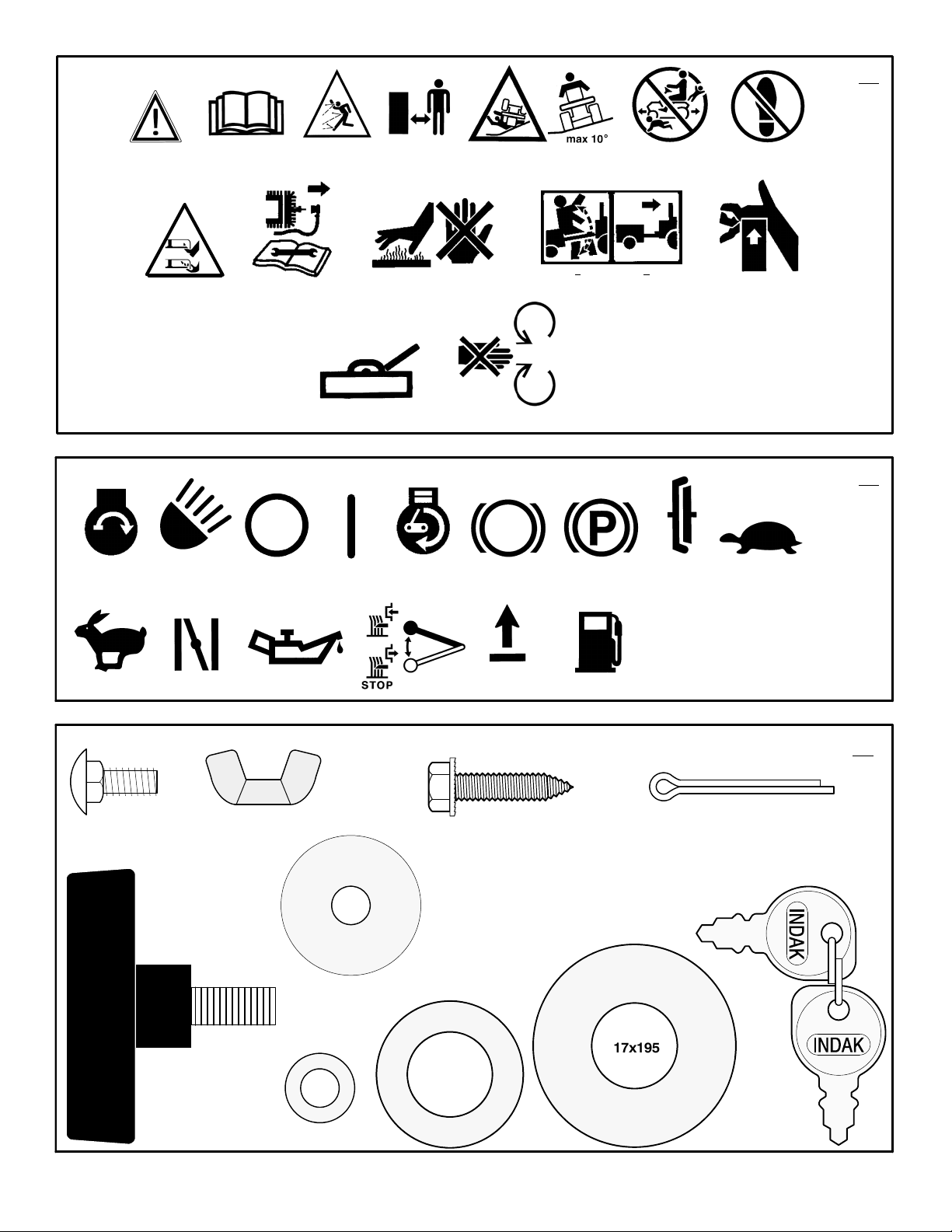
INTERNATIONAL PICTORIALS
IMPORTANT: The following pictorials are located on your unit or on literature supplied
with the product. Before you operate the
unit, learn and understand the purpose for
each pictorial.
NOTE: Illustrations and pictorials begin
on page 2.
Safety Warning Pictorials (Figure 23)
1 WARNING
2 IMPORTANT: Read Owner ’s Manual
Before Operating This Machine.
3 WARNING: Thrown Objects. Keep
Bystanders Away. Read User Instructions
Before Operating This Machine.
4 WARNING: Do Not Use This Machine On
Slopes Greater Than 10 Degrees.
5 DANGER: Keep People, Especially
Children, Away From Unit.
6 DANGER: No Step.
7 DANGER: Keep Feet And Hands Away
From Rotating Blade.
8 DANGER: Disconnect Spark Plug Wire
Before Servicing Unit.
9 WARNING: Hot Surface.
10 WARNING: Use Caution When Connecting
Or Disconnecting Accessories.
11 WARNING: Crushed Fingers.
12 IMPORTANT: Follow Instructions In
Owner’s Manual To Level The Deck.
13 WARNING: Stay Clear Of Mower Blade As
Long As Engine Is Running.
Control And Operating Pictorials
(Figure 24)
1 Engine Start
2 Lights
3 Engine Run
4 Engine Stop
5 Engine Run
6 Brake
7 Parking Brake
8 Clutch
9 Slow
10 Fast
11 Choke
12 Oil
13 Blade Rotation Control
14 Raise
15 Fuel
7102049
5
Page 6

BRIGGS & STRATTON CORPORATION OWNER WARRANTY POLICY
Effective January 1, 2006 replaces all undated Warranties and all Warranties dated before January 1, 2006
LIMITED WARRANTY
Briggs & Stratton Corporation will repair or replace, free of charge, any part(s) of the product that is defective in material or workmanship or both.
Transportation charges on product submitted for repair or replacement under this warranty must be borne by purchaser. This warranty is effective
for the time periods and subject to the conditions stated below. For warranty service, find the nearest Authorized Service Dealer in your area. For
warranty service, find the nearest Authorized Service Dealer in our dealer locator map at www.murray.com.
THERE IS NO OTHER EXPRESS WARRANTY. IMPLIED WARRANTIES, INCLUDING THOSE OF MERCHANTABILITY AND FITNESS FOR A
PARTICULAR PURPOSE, ARE LIMITED TO ONE YEAR FROM PURCHASE, OR TO THE EXTENT PERMITTED BY LAW ANY AND ALL
IMPLIED WARRANTIES ARE EXCLUDED. LIABILITY FOR INCIDENTAL OR CONSEQUENTIAL DAMAGES ARE EXCLUDED TO THE
EXTENT EXCLUSION IS PERMITTED BY LAW. Some states or countries do not allow limitations on how long an implied warranty lasts, and
some states or countries do not allow the exclusion or limitation of incidental or consequential damages, so the above limitation and exclusion
may not apply to you. This warranty gives you specific legal rights and you may also have other rights which vary from state to state or country to
country.
WARRANTY TERMS
Consumer Commercial Condition of
Brand / Unit Use Use Warranty Term
Riders / Tractors 2 years 90 days..................... ...........
en
The warranty period begins on the date of purchase by the first retail consumer or commercial end user, and continues for the period of
time stated in the table above. “Consumer use” means personal residential household use by a retail consumer . “Commercial use” means
all other uses, including use for commercial, income producing or rental purposes. Once product has experienced commercial use, it shall
thereafter be considered as commercial use for purposes of this warranty.
No warranty registration is necessary to obtain warranty on Murray branded products. Save your proof of purchase receipt. If you do not
provide proof of the initial purchase date at the time warranty service is requested, the manufacturing date of the product will be used to
determine the warranty.
ABOUT YOUR WARRANTY
We welcome warranty repair and apologize to you for being inconvenienced. Any Authorized Service Dealer may perform warranty
repairs. Most warranty repairs are handled routinely, but sometimes requests for warranty service may not be appropriate. For example,
warranty service would not apply to the product if damage occurred because of misuse, lack of routine maintenance, shipping, handling,
warehousing or improper installation. Similarly, the warranty is void if the serial number on the product has been removed or the product
has been altered or modified.
This warranty covers product related defective material and/or workmanship only. To avoid misunderstanding which might occur between the customer and the Dealer, listed below are some of the causes of product failure that the warranty does not cover.
• Normal Wear: Small Engine Powered Equipment, like all mechanical devices, needs periodic parts and service to perform well. Warranty does not
cover repair when normal use has exhausted the life of the product or part.
• Installation: This warranty does not apply to product that has been subjected to improper or unauthorized installation, alteration or modification. Nor
installations that prevent starting, cause unsatisfactory engine performance.
• Improper Maintenance: The life of this product depends upon the conditions under which it operates, and the care it receives. Recommended
maintenance and adjustment intervals are stated in the Operator’s Manual. Often product, such as tillers, edgers, rotary mowers, are used in dusty
or dirty conditions, which can cause what appears to be premature wear. Such wear, when caused by dirt, dust, or other abrasive material entering
the product because of improper maintenance is not covered by warranty. The warranty will not cover repairs due to problems caused by replacement parts that are not original manufactured part(s).
• Incorrect and/or insufficient fuel or lubrication: This warranty does not cover damage caused by the use of stale fuel, or altered gasolines. Dam-
age to engine or engine components ie, combustion chamber, valves, valve seats, valve guides, burned starter motor windings caused by use of
alternate fuels such as liquified petroleum, natural gas, are not covered unless engine is certified for this operation. Parts which are scored or broken because product was operated with insufficient, contaminated or incorrect grade of lubricating oil as well as product components damaged due
to lack of lubrication are not covered.
• Operational Misuse: Proper operation of the product is stated in the Operator’s Manual. Product damaged by overspeeding, overheating, or opera-
tion in a confined area without sufficient ventilation. Product broken by excessive vibration caused by a loose engine mounting, loose or unbalanced
blades, impellers, overspeeding, or bent crankshaft due to striking of solid object. Damage or malfunctions resulting from accidents, abuse, or improper servicing or freezing or chemical deterioration, as well as operating in excess of recommended capacities as outlined in the Operator’s
Manual are not covered.
• Routine tune-up, wear items or adjustments: This warranty excludes wear items such as oil, belts, blades, o-rings, filters, etc.
• Other exclusions: Repair or adjustments for part(s) that are not manufactured by Briggs & Stratton Corporation, are not covered, see warranty for
respective manufacturers. This warranty excl udes failures due to acts of God and other force majeure events beyond the manufacturers control. Also excluded are used, reconditioned, and demonstration products.
Warranty service is available only through Authorized Service Dealers. Locate your nearest dealer in our locator map at www.murray.com.
7102049
6
Page 7
OWNER’S INFORMATION
Know your product: If you understand the unit
and how the unit operates, you will get the best
performance. As you read this manual, compare
the illustrations to the unit. Learn the location
and the function of the controls. To help prevent
an accident, follow the operating instructions
and the safety rules. Keep this manual for future
reference.
WARNING: Look for this symbol to indicate
important safety precautions. This symbol
indicates: “Attention! Become Alert! Your
Safety Is At Risk.”
Responsibility Of The Owner
WARNING: This cutting machine is
capable of amputating hands and
feet and throwing objects. Failure
to observe the following safety instructions
could result in serious injury or death to
the operator or bystanders.
The responsibility of the owner is to
follow the instructions below.
SAFE OPERATION PRACTICES
For Ride--On (Riding)
Rotary Mower Machines
Training
1. Read the instructions carefully. Be familiar
with the controls and the proper use of the
equipment.
2. Never allow children or people unfamiliar
with these instructions to use the mower.
Local regulations may restrict the age of
the operator.
3. Never mow while people, especially
children, or pets are nearby.
4. Keep in mind that the operator or user is
responsible for accidents or hazards occurring to other people or their property.
5. Do not carry passengers.
6. All drivers should seek and obtain professional and practical instruction. Such
instruction should emphasize:
a. the need for care and concentration
when working with ride--on machines;
b. control of a ride--on machine sliding
on a slope will not be regained by the
application of the brake. The main
reasons for loss of control are:
• insufficient wheel grip;
• being driven too fast;
• inadequate braking
• the type of machine is unsuitable
for its task;
• lack of awareness of the effect of
ground conditions, especially
slopes;
• incorrect hitching and load dis-
tribution.
Preparation
1. While mowing, always wear substantial
footwear and long trousers. Do not operate
the equipment when barefoot or wearing
open sandals.
7102049
2. Thoroughly inspect the area where the
equipment is to be used and remove all objects which may be thrown by the machine.
3. WARNING -- Petrol is highly flammable.
a. Store fuel in containers specifically de-
signed for this purpose.
b. Refuel outdoors only and do not
smoke while refuelling.
c. Add fuel before starting the engine.
Never remove the cap of the fuel tank
or add petrol while the engine is running or when the engine is hot.
d. If petrol is spilled, do not attempt to
start the engine but move the machine
away from the area of spillage and
avoid creating any source of ignition
until petrol vapours have dissipated.
e. Replace all fuel tanks and container
caps securely.
4. Replace faulty silencers.
5. Before using, always visually inspect to see
that the blades, blade bolts and cutter assembly are not worn or damaged. Replace
worn or damaged blades and bolts in sets
to preserve balance.
6. On multi--blade machines, take care as rotating one blade can cause other blades to
rotate.
Operation
1. Do not operate the engine in a confined
space where dangerous carbon monoxide
fumes can collect.
2. Mow only in daylight or in good artificial
light.
3. Before attempting to start the engine, disengage all blade attachment clutches and
shift into neutral.
4. Do not use on slopes of more than 10 degrees.
5. Remember there is no such thing as a
“safe” slope. Travel on grass slopes requires particular care. To guard against
overturning:
a. do not stop or start suddenly when
going up or downhill;
b. engage clutch slowly, always keep
machine in gear, especially when travelling downhill;
c. machine speeds should be kept low
on slopes and during tight turns;
d. stay alert for humps and hollows and
other hidden hazards;
e. never mow across the face of the
slope, unless the mower is designed
for this purpose.
6. Use care when pulling loads or using heavy
equipment.
a. Use only approved drawbar hitch
points.
b. Limit loads to those you can safely
control.
c. Do not turn sharply. Use care when
reversing.
d. Use counterweight(s) or wheel
weights when suggested in the Instruction Book.
7. Watch out for traffic when crossing or near
roadways.
8. Stop the blades rotating before crossing
surfaces other than grass.
9. When using any attachments, never direct
discharge of material toward bystanders
7
en
nor allow anyone near the machine while in
operation.
10. Never operate the mower with defective
guards or shields, or without safety protective devices in place.
11. Do not change the engine governor settings or overspeed the engine. Operating
an engine at excessive speed may increase the hazard of personal injury.
12. Before leaving the operator’s position
a. disengage the power take--off and
lower the attachments;
b. change into neutral and set the park-
ing brake;
c. stop the engine and remove the key.
13. Disengage drive to attachments, stop the
engine, and disconnect the spark plug
wire(s) or remove the ignition key
a. before cleaning blockages or unclog-
ging chute;
b. before checking, cleaning or working
on the mower;
c. after striking a foreign object. Inspect
the mower for damage and make repairs before restarting and operating
the equipment;
d. if the machine starts to vibrate abnor-
mally (check immediately).
14. Disengage drive to attachments when
transporting or not in use.
15. Stop the engine and disengage drive to attachment
a. before refuelling;
b. before removing the grass catcher;
c. before making height adjustment un-
less adjustment can be made from the
operator’s position.
16. Reduce the throttle setting during engine
run--out and, if the engine is provided with a
shut--off valve, turn the fuel off at the conclusion of mowing.
17. Before and when backing, look behind and
down for small children.
18. Use extra care when approaching blind
corners, shrubs, trees or other objects that
may obscure vision.
Maintenance and Storage
1. On multi--blade machines, take care as rotating one blade can cause other blades to
rotate.
2. When machine is to be parked, stored or
left unattended, lower the cutting means
unless a positive mechanical lock is used.
3. Keep all nuts, bolts, and screws tight to be
sure the equipment is in safe working
condition.
4. Never store the equipment with petrol in the
tank inside a building where fumes may
reach an open flame or spark.
5. Allow the engine to cool before storing in
any enclosure.
6. To reduce the fire hazard, keep the engine,
silencer, battery compartment and petrol
storage area free of grass, leaves, or excessive grease.
7. Check the grass catcher frequently for
wear or deterioration.
8. Replace worn or damaged parts for safety.
9. If the fuel tank has to be drained, this
should be done outdoors.
Page 8
ASSEMBLY
f
All fasteners are in the parts bag. Do not discard
any parts or material until the unit is assembled.
WARNING: Before doing any assembly or maintenance to the
mower, remove the wire from the
spark plug.
NOTE: In this instruction book, left and right
describe the location of a part with the operator on the seat.
NOTE: Illustrations and pictorials begin on
page 2.
NOTE: To assemble the following loose
parts, use the fasteners shown at full size in
Figure 25.
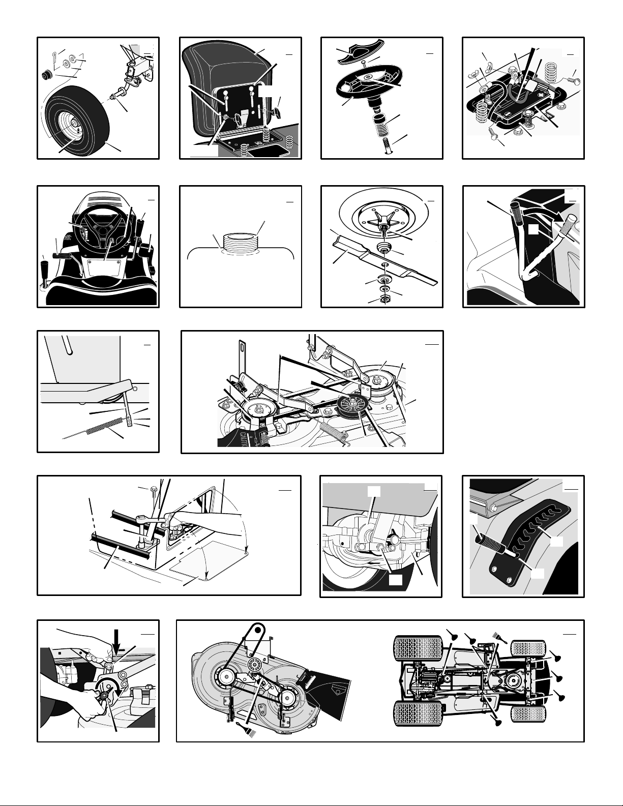
How To Install The Front Wheels
(Figure 1)
Use a knife and cut the four sides of the container. Install the front wheels (1) in the container.
NOTE: Use a piece of wood about 4 feet (1.25
meters) long to raise the front of the tractor.
If a piece of wood cannot be found, get
another person to help lift the tractor. Be
careful, do not let the tractor fall.
1. Raise the front of the tractor. Set a support
(block of wood) under the tractor.
2. Make sure the valve stem (2) is to the outside of the tractor. Slide the front wheel (1)
on the spindle (3).
3. Fasten each front wheel (1) with washer (4)
and cotter pin (5). Bend the ends of the
cotter pin (5) appart to keep the front wheel
(1) on the spindle (3).
4. Fasten each front wheel (1) with washer (4)
and e--ring (5).
5. After the front wheels (1) are installed, lift
the tractor from the support. Roll the tractor
off of the container.
6. If your tractor has hub caps (6), install the
hub caps (6). Make sure the washers (4)
hold the hub caps (6) in place.
How To Install The Seat (Figure 2)
1. Carefully remove the plastic bag from the
seat (1).
2. Align the holes in the seat hinge (2) to the
holes in the seat (1). Fasten the seat (1) to
the seat hinge (2) with the fasteners (4) and
(5).
3. Check the operating position of the seat (1).
If the seat (1) needs to be adjusted, loosen
the two wing bolts (5). Slide the seat (1) forward or backward along the seat adjusting
holes (3). Tighten the wing bolts (5).
How To Assemble The Steering Wheel
(Figure 3)
1. Make sure the front wheels point forward.
2. Slide the cover (3) over the steering post
(2). Make sure the collar of the cover (3) is
on top.
3. Slide the steering wheel (1) onto the steer-
ing post (2).
4. Attach the steering wheel (1) to the steering post (2) with screw (4) and washer (6).
5. Some models have an optional insert (7) in
the parts bag. Attach the insert (7) to the
centre of the steering wheel (1).
Maintenance Free Battery (Figure 4)
IMPORTANT: Before you attach the battery
cables to the battery, check the battery date.
The battery date tells if the battery must be
charged.
1. Check the top and the side of the battery (1)
for the location of the battery date.
2. If the battery (1) is put into service before
the , the battery cables can be attached without charging the battery (1). See “How To
Install The Battery Cables”.
3. If the battery (1) is put into service after the ,
the battery (1) must be charged. See “How
To Charge The Maintenance Free Battery”.
How To Charge The Battery (Figure 4)
WARNING: When you charge the
battery, do not smoke. Keep the bat-
tery away from any sparks. The
fumes from the battery acid can cause an
explosion.
1. Remove the battery (1) and battery tray (3).
2. Remove the protective cap from the battery
terminal.
3. Use a 12 volt battery charger to charge the
battery (1). Charge at a rate of 6 amperes
for one hour. If you do not have a battery
charger, have an authorized service centre
charge the battery.
4. Install the battery (1) and battery tray (3).
Make sure the positive (+) terminal (4) is on
the left side.
en
How To Install The Battery Cables
(Figure 4)
WARNING: To prevent sparks, fasten
the red cable to the positive (+) terminal before you connect the black
cable.
1. Remove the protective cap from the battery
terminal.
2. Slide the terminal cover (2) onto the red
cable (5). Fasten the red cable (5) to the
positive (+) terminal (4) with the fasteners
(6) and (7).
3. Fasten the black cable 8 to the negative (--)
terminal with the fasteners (6) and (7).
Check The Tyres
Check the air pressure in the tyres. Tyres with
too much air pressure will cause the unit to ride
rough. Also, the wrong air pressure will keep the
mower housing from cutting level. The correct
air pressure is: Front Tyres 0,97 BAR (14 PSI),
Rear Tyres 0,69 BAR (10 PSI). The tyres were
over inflated for shipment.
Check The Level Of The Mower
Housing
Make sure the level of cut is still correct. After
you mow a short distance, look at the area that
was cut. If the mower housing does not cut level,
see the instructions on “How To Level The
Mower Housing” in the Maintenance section of
this instruction book.
How To Prepare The Engine
NOTE: The engine was shipped from the factory filled with oil. Check the level of the oil.
Add oil as needed.
See the engine manufacturer’s instructions for
the type of petrol and oil to use. Before you use
the unit, read the information on safety, operation, maintenance, and storage.
WARNING: Follow the engine manufacturer’s instructions for the type o
petrol and oil to use. Always use a
safety petrol container. Do not smoke when
adding petrol to the engine. When inside an
enclosure, do not fill with petrol. Before you
add petrol, stop the engine. Let the engine
cool for several minutes.
Important! Before You Start Mowing
U Check the engine oil.
U Fill the fuel tank with petrol.
U Check the air pressure of the tyres.
U Check the level of the mower hous-
ing.
U Attach the battery cables.
7102049
8
Page 9
OPERATION
NOTE: Illustrations and pictorials begin on
page 2.
Location Of Controls
(Figure 5, Figure 20 )
Blade Rotation Control (1): Use the blade rotation control to start and stop the rotation of the
blade.
Brake Pedal (2): Use the brake pedal to quickly
stop.
Headlight Switch (3): The headlight switch is
the first part of the ignition switch. To use the
lights with the engine running, turn the key to the
position for the lights.
Ignition Switch (3): Use the ignition switch to
start and stop the engine.
Speed Control Pedal (4): Use the speed control pedal to change the speed and the direction
of the unit.
Lift Lever (5): Use the lift lever to change the
height of cut.
Parking Brake Lever (6): Use the parking brake
lever to engage the brake when you leave the
unit.
Throttle Control Lever (7): Use the throttle
control lever to increase or decrease the speed
of the engine.
(Figure 20) Automatic Drive disconnect (1):
use the automatic drive disconnect, located
under the seat, to disengage the transmission.
Attachments
This unit can use many different attachments.
This unit can pull attachments like a lawn
sweeper, a lawn aerator, or a hopper spreader.
This unit can not use attachments that engage
the ground like a plough, a disk harrow, or a
cultivator.
For trailer and pull--behind attachments, the
maximum weight is 113 kg (250 lbs.).
How To Use The Throttle Control
(Figure 5)
Use the throttle control (7) to increase or decrease the speed of the engine.
1. The FAST position is marked with a detent.
For normal operation and when using a
grass bagger, move the throttle control to the
FAST position. For maximum charging of the
battery and for a cooler running engine, operate the engine in the FAST position.
2. The engine governor is set at the factory for
maximum performance. Do not adjust the
governor to increase the speed of the engine.
How To Use The Blade Rotation Control
(Figure 5)
Use the blade rotation control (1) to engage
the blade(s).
1. Before you start the engine, make sure the
blade rotation control (1) is in the DISENGAGE position.
7102049
2. Move the blade rotation control (1) to the
ENGAGE position to rotate the blade(s).
NOTE: If the engine stops when you engage the blade(s), the seat switch is not
activated. Make sure you sit in the middle
of the seat.
3. Move the blade rotation control (1) to the
DISENGAGE position to stop the blade(s).
Before you leave the operator’s position,
make sure the blade(s) has stopped rotating.
4. Before you ride the unit across a sidewalk or
a road, move the blade rotation control (1)
to the DISENGAGE position.
WARNING: Always keep your
hands and feet away from the
blade, deflector opening, and the
mower housing when the engine runs.
How To Use The Speed Control Pedal
(Figure 5)
The drive system uses a Hydrostatic Automatic
Drive transmission. The Hydrostatic transmission is very easy to operate. This type of
drive system does not require a shift lever or a
clutch pedal.
The speed and direction of travel is controlled by
a single speed control pedal (4) operated with
your right foot. Do not use the left brake pedal in
normal operation. Only use the left brake pedal
to quickly stop in an emergency.
How To Drive Forward
1. (Figure 20) The automatic drive disconnect (1) must be in the DRIVE position (2).
2. Slowly release your left foot from the brake
pedal.
3. Move the throttle control to the FAST position.
4. (Figure 19) Slowly push the speed control
pedal (1) forward (4) to the desired speed.
5. To increase forward speed, slowly move the
speed control pedal (1) forward. To reduce
forward speed, slowly release the speed
control pedal (1) until the unit slows to the
desired speed.
How To Drive In Reverse
1. Look to the rear.
2. Slowly push the speed control pedal (1) to
the REVERSE position (2).
How To Change Directions
CAUTION: To change directions, do not use
the left brake pedal. Use only the speed control pedal.
1. Slowly remove your foot from the speed
control pedal (1).Thespeed control pedal
(1) will automatically return to the NEUTRAL
position (3).
2. When the unit stops, slowly move the speed
control pedal (1) to the desired direction.
How To Disconnect The Transmission
(Figure 20)
To push the unit, use the automatic drive disconnect (1) to release the transmission. The
automatic drive disconnect (1) is under the
seat.
1. The engine must be off.
9
en
2. Raise the seat. The automatic drive disconnect (1) is under the seat.
3. Move and latch the automatic drive disconnect (1) in the PUSH position (3). The
transmission is now released and the unit
can be pushed.
NOTE: In cold weather, the heavy viscosity oil in the transmission will make the
unit difficult to push.
4. To engage the transmission, unlatch the automatic drive disconnect (1). The trans-
mission is now connected and ready to
operate.
How To Use The Parking Brake
(Figure 5)
1. Completely push the brake pedal (2) forward.
2. Lift the parking brake lever (6).
3. Remove your foot from the brake pedal (2)
and then release the parking brake lever
(6). Make sure the parking brake will hold the
unit.
4. To release the parking brake (6), completely
push the brake pedal (2) forward. The parking brake will automatically release.
WARNING: Before you leave the
operator’s position, set the parking
brake. Move the blade rotation control to the DISENGAGE position. Stop the
engine and remove the ignition key.
How To Change The Cutting Height
(Figure 5)
To change the cutting height, raise or lower the
lift lever (5) as follows.
1. Move the lift lever (5) forward to lower the
mower housing and back to raise the mower
housing.
2. When you ride on a sidewalk or road, move
the lift lever (5) to the highest position and
move the blade rotation control to the DISENGAGE position.
How To Stop The Unit (Figure 5)
1. Slowly remove your foot from the speed
control pedal (4). The speed control pedal
(1) will automatically return to the NEUTRAL
position and the unit will stop.
2. Move the blade rotation control (1) to the
DISENGAGE position.
3. Set the parking brake (6).
WARNING: Make sure the parking
brake will hold the unit.
4. Move the throttle control (7) to the SLOW
position.
5. To stop the engine, turn the ignition key (3)
to the OFF position. Remove the key.
How To Transport The Unit
To transport the unit, follow the steps below.
1. Move the blade rotation control to the DISENGAGE position.
2. Raise the lift lever to the highest position.
Page 10
3. Move the throttle control to a position between SLOW and FAST.
4. Slowly push the speed control pedal forward
to the desired speed.
How To Operate With The Mower
Housing
IMPORTANT: When you operate with the
mower housing, always operate with the
throttle control in the FAST position.
1. Start the engine.
2. Move the lift lever to a height of cut position.
In high or thick grass, cut the grass in the
highest position first and then lower the
mower housing to a lower position.
3. Move the throttle control to the SLOW position.
4. Slowly move the blade rotation control to the
ENGAGE position.
5. Move the throttle control to the FAST position.
6. Slowly push the speed control pedal to the
desired speed.
NOTE: When you mow in heavy grass or
mow with a bagger, use a slow forward
speed.
7. Make sure the level of cut is still correct.
After you mow a short distance, look at the
area that was cut. If the mower housing does
not cut level, see the instructions on “How To
Level The Mower Housing” in the Maintenance section.
WARNING: For better control of the
unit, select a safe speed.
How To Operate On Hills
WARNING: Do not ride up or down
slopes that are too steep to back
straight up. Never ride the unit
across a slope.
1. Control the speed only with the speed control
pedal. Do not use the brake pedal on a hill.
2. To help prevent an accident, slowly move the
speed control pedal. Avoid sudden turns or
changes in speed.
3. To reduce forward speed when going down a
hill, slowly release the speed control pedal
until the unit slows to the desired speed.
HowToStopOnaHill
1. Avoid stopping on a hill. If you must quickly
stop in an emergency, remove your right foot
from the speed control pedal and quickly depress the left brake pedal.
2. Set the parking brake.
3. Before you dismount from the seat, move the
throttle control to the SLOW position, move
the blade rotation controlattachment clutch to
the DISENGAGED position, turn off the engine and set the parking brake.
How To Start Operation On A Hill
1. Start the engine
2. Move the blade rotation controlattachment
clutch to the ENGAGED position.
3. Move the throttle control to the FAST position.
4. Depress the brake pedal and release the
parking brake. As you release the parking
brake, push the speed control pedal to the
desired speed.
Slowly push the speed control
pedal as you release the parking
brake. The parking brake must be
disengaged before the speed control pedal
is able to engage the transmission.
Before Starting The Engine
Check the oil
NOTE: The engine was shipped from the factory filled with oil. Check the level of the oil.
Add oil as needed. See the engine manufacturer’s instructions for the type of petrol and
oil to use.
1. Make sure the unit is level.
NOTE: Do not check the level of the oil
while the engine runs.
2. Check the oil. Follow the procedure in the
engine manufacturer’s instructions.
3. If necessary, add oil until the oil reaches the
FULL mark on the dipstick. The quantity of oil
needed from ADD to FULL is shown on the
dipstick. Do not add too much oil.
Add Petrol
WARNING: Always use a safety
petrol container. Do not smoke
when adding petrol to the fuel tank.
Do not add petrol when you are inside an
enclosure. Before you add petrol, stop the
engine and let the engine cool for several
minutes.
(Figure 6) Fill the fuel tank (1) to the FULL (2)
position with regular unleaded petrol. Do not use
premium unleaded petrol. Make sure the petrol
is fresh and clean. Leaded petrol will increase
deposits and shorten the life of the valves.
How To Start The Engine
WARNING: The electrical system
has an operator presence system
that includes a sensor switch for
the seat. These components tell the
electrical system if the operator is sitting
on the seat. This system will stop the
engine when the operator leaves the seat.
For your protection, always make sure this
system operates correctly.
NOTE: The engine will not start unless you
depress the clutch/brake pedal and move the
blade rotation control to the DISENGAGE
position.
en
1. Push the clutch/brake brake pedal completely forward. Keep your foot on the pedal.
2. Make sure the blade rotation control is in the
DISENGAGE position.
3. Move the throttle control completely forward
to the CHOKE or FAST position. Some models have a separate choke knob. Pull the
choke knob to the full CHOKE position.
4. Turn the ignition key to the START position.
NOTE: If the engine does not start after
four or five tries, move the throttle control
to the FAST position. Again try to start the
engine. If the engine will not start, see the
TROUBLE SHOOTING CHART.
5. Slowly move the throttle control to the SLOW
position.
6. To start a hot engine, move the throttle control to a position between FAST and SLOW.
Mowing And Bagging Tips
1. For a lawn to look better, check the cutting
level of the mower housing. See “How To
Level The Mower Housing” in the Maintenance section.
2. For the mower housing to cut level, make
sure the tyres have the correct amount of air
pressure.
3. Every time you use the unit, check the blade.
If the blade is bent or damaged, immediately
replace the blade. Also, make sure the nut
for the blade is tight.
4. Keep the blade(s) sharpened. Worn blades
will cause the ends of the grass to turn
brown.
5. Do not cut or bag grass that is wet. Wet
grass will not discharge correctly. Let the
grass dry before cutting.
6. Use the left side of the mower housing to trim
near an object.
7. Discharge the cut grass onto the mowed
area. The result is a more even discharge of
cut grass.
8. When you mow large areas, start by turning
to the right so that the cut grass will discharge away from shrubs, fences, driveways,
etc. After one or two rounds, mow in the opposite direction making left turns until finished.
9. If the grass is very high, cut two times to decrease the load on the engine. First cut with
the mower housing in the highest position
and then lower the mower housing for the
second cut.
10.For better engine performance and an even
discharge of the cut grass, always operate
the engine with the throttle in FAST position.
11.When you use a bagger, operate the engine
with the throttle in FAST position and the
speed control pedal pushed 1/3 to 1/2 forward..
12.After each use, clean the bottom and top of
the mower housing for better performance.
Also, a clean mower housing will help prevent a fire.
7102049
10
Page 11
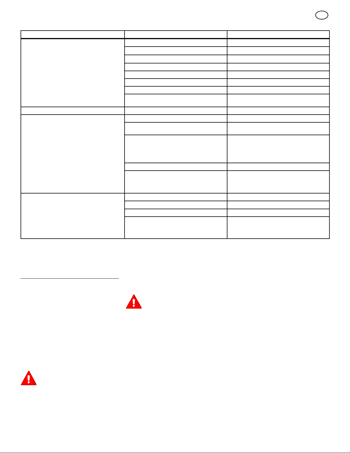
MAINTENANCE CHART
FREQUENCY MAINTENANCE REQUIRED COMMENTS
Daily or before each use Maintenance engine. Refer to the Engine Owner’s Manual.
Examine blade(s).
Remove debris from unit and mowing area.
Examine all rotating and sliding parts.
Check tire inflation. Refer to the Maintenance section.
Verify that the mower housing is level. Refer to the Maintenance section.
Examine V--belts. Check for cracks, wear, and excessive damage.
Check brake operation. Refer to the Operation and Maintenance
After completion of first 5 hours Change oil. Refer to the Engine Owner’s Manual.
After 25 hours Maintenance engine. Refer to the Engine Owner’s Manual.
Remove, examine, sharpen, and balance
blade(s).
Check adjustments:
a. Blade Rotation Control
b. Brake
c. Clutch
d. Steering
Lubricate chassis and mower housing. Refer to Where to Lubricate instructions.
Check the muffler:
a. Torque
b. For wear or burn out
c. Condition of spark arrestor, (if applicable).
Before storage of 30 days or more Prepare engine for storage. Refer to the Engine Owner’s Manual.
Drain fuel system. Refer to warnings in the Owner’s Manual.
Add fuel stabilizer. Refer to the Engine Owner’s Manual.
Prepare battery for storage:
a. Remove from unit.
b. Fully charge.
c. Move to cool dry place.
Check for cracks, wear, and excessive damage.
sections.
Refer to Maintenance section.
Refer to Maintenance section.
Refer to Maintenance section.
en
MAINTENANCE
NOTE: Illustrations and pictorials begin on
page 2.
General Recommendations
1. The owner’s responsibility is to maintain this
product. This will extend the life of the product and is also necessary to maintain warranty coverage.
2. Check the spark plug, drive brake, lubricate
the unit, and clean the air filter once a year.
3. Check the fasteners. Make sure all fasteners
are tight.
4. Follow the Maintenance section to keep the
unit in good operating condition.
WARNING: Before you make an inspection, adjustment, or repair to
the unit, disconnect the wire to the
spark plug. Remove the wire from the
spark plug to prevent the engine from
starting by accident.
NOTE: Torque is measured in foot pounds
(metric Nm). This measurement describes
how tight a nut or bolt must be. The torque is
measured with a torque wrench.
7102049
Inspect Blade (Figure 7)
WARNING: Before you inspect or
remove the blade, disconnect the
wire to the spark plug. If the blade
hits an object, stop the engine. Check the
unit for damage. The blade has sharp
edges. When you hold the blade, use
gloves or cloth material to protect your
hands.
If you keep the blade (1) sharp and inspect the
blade for damage, the blade will cut better and
be more safe to operate. Frequently check the
blade for excessive wear, cracks, or other damage. Frequently check the nut (3) that holds the
blade (1). Keep the nut (3) tight. If the blade hits
an object, stop the engine. Disconnect the wire
to the spark plug. See if the blade is bent or
damaged. Check the blade adapter (5) for damage. Before you operate the unit, replace damaged parts with original equipment parts. See
the authorized service centre in your area. Every
three years, have an authorized service person
inspect the blade or replace the old blade with
an original equipment part.
11
How To Remove And Install The Blade
(Figure 7)
1. Remove the mower housing. See the instructions on “How To Remove The Mower Housing”.
2. Use a piece of wood to keep the blade from
rotating.
3. Remove the nut (3) that holds the blade (1).
4. Check the blade (1) and the blade adapter
(5) according to the instructions for “Inspect
Blade”. Replace a badly worn or damaged
blade with an original equipment blade. See
an authorized service centre in your area.
5. Clean the top and bottom of the mower housing. Remove all the grass and debris.
6. Mount the blade (1) and blade adapter (5)
on the mandrel (6).
7. Mount the blade (1) so that the hi--lift edges
(7) are up. If the blade is upside down, the
blade will not cut correctly and can cause an
accident.
8. Fasten the blade (1) with the original
washers and nut (3). Make sure the outside
rim of the Belleville washer (2) is against
the blade (1).
Page 12
WARNING: Always keep the nut (3)
tight that holds the blade (1). A
loose nut or blade can cause an
accident.
9. Tighten the nut (3) that holds the blade (1) to
a torque of 30 foot pounds (41,5 Nm).
10.Install the mower housing. See “How To Remove The Mower Housing”.
How To Adjust The Blade Rotation
Control
WARNING: To prevent an injury, the
blade rotation control must operate
correctly.
In normal usage, the blade rotation control will
not require an adjustment. However, if the cutting performance decreases or the quality of cut
is poor, make the following changes.
1. When you mow, make sure the throttle control in in the FAST position.
2. (Figure 8) Move the blade rotation control to
the DISENGAGE position (1).
3. Stop the engine. Disconnect the wire from
the spark plug.
4. Check the blade(s). Keep a sharp edge on
the blade(s). A blade that is not sharp will
cause the tips of the grass to become brown.
5. (Figure 9) Disconnect the blade drive
spring (2) from the blade control rod (1).
Move the blade drive spring (2) to the
middle hole (4). This will increase the tension on the mower drive belt.
6. Attach the wire to the spark plug. Mow for a
short distance and again check the quality of
cut. If necessary, move the blade drive
spring (2) to the bottom hole (5)
7. Again check the quality of cut. If the quality of
cut has not improved, replace the mower
drive belt. See “How To Replace The Mower
Drive Belt”. If the replacing the belt does not
correct the problem, take the unit to an authorized service centre.
8. Move the blade rotation control to the DISENGAGE position. Stop the engine.
9. (Figure 10) Check the operation of the blade
brake. Rotate the pulleys with your hand.
Make sure the brake pads (1) are pressed
tightly against the pulleys
WARNING: If the brake pads (1) do
not press tightly against the
pulleys, take the unit to an author-
ized service centre.
10.(Figure 8) Move the blade rotation control to
the ENGAGE position (2).
11. (Figure 10) Check the pads for the blade
brake (7). If the pads are excessively worn
or damaged, replace the brake pad assemblies. Correct replacement parts and assistance are available from an authorized
service centre.
12.Attach the wire to the spark plug. Mow for a
short distance and again check the operation
of the blade rotation control.
13.When you move the blade rotation control to
the DISENGAGE position, all movement will
stop within five seconds. If there is movement of the belt or the blades continue to rotate, engage and disengage the blade
rotation control five times to remove any ex-
7102049
cess rubber from a new mower drive belt. If
you need assistance, take the unit to an
authorized service centre.
14.(Figure 9) If you replace the mower drive
belt, move the blade drive spring (2) to the
top hole (3).
How To Check And Adjust The Motion
Drive Belt (Figure 18 and Figure 21)
If the motion drive belt is loose, the belt will slip
when; going up a hill, pulling a heavy load, or the
unit will not move forward.
IMPORTANT: Always operate with the engine
speed in the FAST position. If the engine
speed is in a slow or moderate position, the
engine and transmission can become too hot
and cause problems that are similar to a
loose motion drive belt.
WARNING: Before you make an inspection, adjustment, or repair to
the unit, disconnect the wire to the
spark plug. Remove the wire from the
spark plug to prevent the engine from
starting by accident.
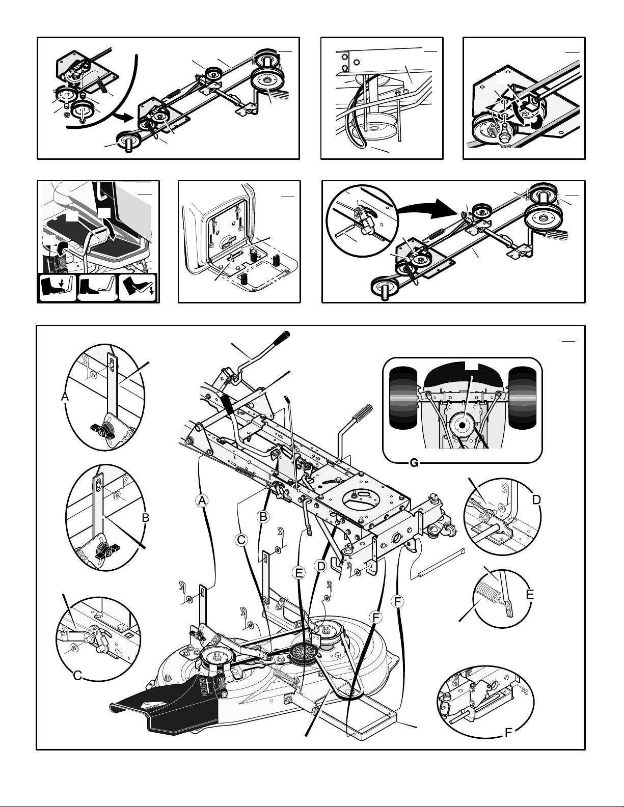
1. (Figure 21) Check the routing of the motion
drive belt (6). Make sure the motion drive
belt (6) is installed correctly and is inside all
the belt guides (7).
2. (Figure 18) Disconnect the clutch link (1)
from the idler arm (2).
3. (Figure 21) Align the hole in the brake lever
(3) with the hole in the frame. Hold the brake
lever (3) in place with a 1/4 inch (6 mm) pin
or bolt (4).
4. (Figure 18) Rotate the clutch link (1) until
the mounting hole (5) in the clutch link (1)
is aligned with the mounting hole (5) in the
idler arm (2).
5. Connect the clutch link (1) to the idler arm
(2).
6. (Figure 21) Remove the 1/4inch(6mm)
pin or bolt (4).
7. If the belt still slips after the belt has been
adjusted, then the motion drive belt is worn
or damaged and must be replaced. See
“How To Replace The Motion Drive Belt”.
How To Check And Adjust The Drive
Brake (Figure 12 and 20)
(Figure 20) Set the parking brake. Move the au-
tomatic drive disconnect (1) to the PUSH
position (3). Push the unit. If the rear wheels
rotate, adjust or replace the brake pads.
Adjust the drive brake (4) as follows:
1. (Figure 12) The location of the drive brake
(4) is on the right side of the gearbox (5).
2. (Figure 20) Make sure the parking brake is
set and the automatic drive disconnect (1)
is in the PUSH position (3).
3. (Figure 12) Turn the hex nut (6) inaclockwise direction until the rear wheels do not
turn when the unit is pushed forward.
4. Release the parking brake and push the unit.
If the unit does not roll, turn the hex nut (6)
in a counter--clockwise direction until the unit
rolls.
5. Set the parking brake. Push the unit. If the
rear wheels do not turn, the drive brake (4)
12
en
is correctly adjusted. Release the parking
brake.
WARNING: If you cannot correctly
adjust the drive brake, replace the
brake pads. Correct replacement
parts and assistance are available from an
authorized service centre.
How To Remove The Battery (Figure 4)
To charge or clean the battery (1), remove the
battery (1) from the unit as follows.
WARNING: To prevent sparks, dis-
connect the black battery cable (8)
from the negative (--) terminal before you disconnect the red cable (5).
WARNING: The battery contains
sulphuric acid which is harmful to
the skin, eyes and clothing. If the
acid gets on the body or clothing, wash
with water.
1. Disconnect the black cable (8) from the
negative (--) terminal.
2. Disconnect the red cable (5) from the posi-
tive (+) terminal (4).
3. Lift the battery tray (3) and the battery (1)
out of the unit.
How To Charge The Battery (Figure 4)
WARNING: When you charge the
battery, do not smoke. Keep the
battery away from any sparks. The
fumes from the battery acid can cause an
explosion.
1. Before you charge the battery (1), remove
the battery (1).
2. To charge the battery (1),usea12voltbattery charger. Charge at a rate of 6 amperes
for 1 hour.
3. Install the battery (1).
WARNING: To prevent sparks,
fasten the red cable to the positive
(+) terminal before you connect the
black cable.
4. Fasten the red cable (5) to the positive (+)
terminal (4) with the fasteners as shown.
5. Fasten the black cable (8) to the negative
(--) terminal with the fasteners as shown.
How To Level The Mower Housing
(Figure 13 and Figure 14)
If the mower housing is level, the blade will cut
easier and the lawn will look better.
WARNING: Before you make an inspection, adjustment, or repair to
the unit, disconnect the wire to the
spark plug. Remove the spark plug wire to
prevent the engine from starting by accident
1. Make sure the unit is on a hard flat surface.
2. Check the air pressure in the tyres. If the air
pressure is incorrect, the mower housing will
not cut level. Make sure the tyres are inflated
to: Front Tyres 0,97 BAR (14 PSI), Rear
Tyres 0,69 BAR (10 PSI).
3. (Figure 13) Move the lift lever (1) to the
lowest cut position (2).
Page 13
WARNING: The lifter lever (3) is
spring loaded. Make sure the lift
lever (3) is locked in the lowest cut
position (2).
4. (Figure 14) Loosen the left and right adjuster knobs (1). Push down on each side of
the mower housing. Make sure both sides of
the mower housing are setting on a flat surface. Also, make sure the lift links are loose
and can easily move up or down.
5. Push down on the lift links (2) and tighten
the left and right adjuster knobs (1).Make
sure the adjuster knobs (1) are tight. If
necessary, use a wrench to tighten the ad-
juster knobs (1).
6. (Figure 13) Raise the lift lever (1).
7. Mow for a short distance. If the height of cut
is not level, repeat the above steps.
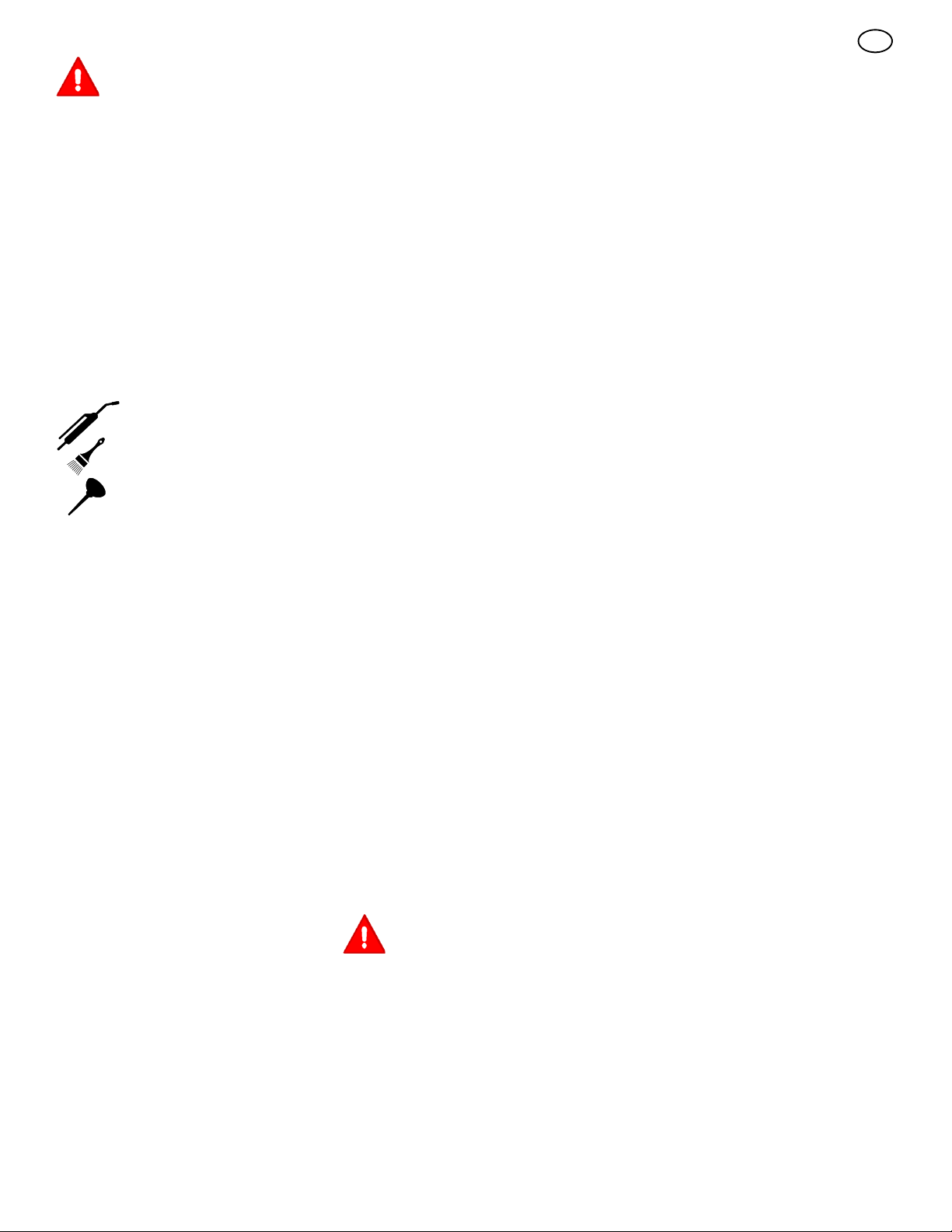
Where To Lubricate (Figure 15)
Models with grease fittings:
Lubricate with grease gun.
Apply grease with a brush to
the areas shown.
Lubricate the areas shown
with engine oil.
NOTE: Apply grease to the steering gear assembly.
CAUTION: If the unit is operated in dry areas
that have sand, use a dry graphite spray to
lubricate the unit.
Check The Tyres
Check the air pressure in the tyres. Tyres with
too much air pressure will cause the unit to ride
rough. Also, the wrong air pressure will keep the
mower housing from cutting level. The correct
air pressure is: Front Tyres 0,97 BAR (14 PSI),
Rear Tyres 0,69 BAR (10 PSI).
How To Replace The Motion Drive Belt
1. Remove the mower housing. See the instructions on “How To Remove The Mower Housing”.
2. (Figure 16) Remove the mid--idler pulley
(4).
3. Disconnect the idler spring (7).
4. Remove the idler pulley (8) and spacer (9).
5. Remove the V--ilder pulley (5) and spacer
(13).
6. Remove the motion drive belt (1) from the
drive pulley (6).
7. (Figure 17) To re m ov e the motion drive belt
(1) from the stack pulley (2), pull the front
end of the belt under the stack pulley (2)
and then back between the stack pulley and
the steering plate (3).
8. (Figure 11) Remove the access panel (10).
9. Remove the two screws (11) that attach the
steering shaft assembly (12).Raisethe
steering wheel and steering shaft assembly
(12). Pull the motion drive belt (1) under the
steering shaft assembly (12).
10.Remove the motion drive belt (1). A correct
replacement part or assistance is available
from an Authorized Service Center in your
area.
11.To install the motion drive belt, reverse the
above steps.
12.(Figure 16) Check the routing of the motion
drive belt (1). Make sure the motion drive
belt is installed correctly on the idler pulleys.
13.Before you use the unit, check the adjustment of the clutch. See the instructions “How
To Check And Adjust The Clutch”.
14.Install the mower housing. See the instructions “How To Install The Mower Housing”.
How To Replace The Mower Drive Belt
(Figure 10)
1. Remove the mower housing. See the instructions on “How To Remove The Mower Housing”.
2. Pull the belt retainer (1) away from the idler
pulley (2) and remove the mower drive belt
(3).
3. Pull the belt retainer (4) away from the right
mandrel pulley (5) and remove the mower
drive belt (3).
4. Pull the belt retainer (4) away from the left
mandrel pulley (6) and remove the mower
drive belt (3). A correct replacement part or
assistance is available from an Authorized
Service Centre in your area.
5. To install the mower drive belt, reverse the
above steps.
How To Remove The Mower Housing
(Figure 22)
1. Move the blade rotation control (1) to the
DISENGAGE position.
2. Move the lift lever (2) to the level adjustment position.
The lift lever is spring loaded. Make
sure the lift lever is locked in the
LEVEL ADJUSTMENT position.
3. Remove the hair pins and the washers from
the adjuster arms (3). See illustrations “C”
and “D”.
en
4. Remove the hair pins and washers from the
suspension links (4). See illustrations “A”
and “B”.
5. Disconnect the extension spring (5) from
the blade control rod (6). See illustration
“E”.
6. Disconnect the front hanger (9) from the
axle support. See illustration “F”.
7. Remove the mower drive belt (7) from the
stack pulley (8).
8. Pull the mower housing away from the right
side of the unit.
9. To install the mower housing, reverse the
above steps.
How To Replace The Fuse
If the fuse is blown, the engine will not start.
Remove the fuse and replace with a 15 amp.
automotive fuse.
Storage (over 30 days)
At the end of each year, prepare the unit for storage as follows.
1. Drain the fuel from the carburettor and the
fuel tank. Change the engine oil. See the engine manufacturer’s instructions.
2. Clean the entyre unit.
3. Charge the battery.
How To Order Replacement Parts
The replacement parts are shown either on the
back pages of this Instruction Book or in a separate Parts List Book.
Use only manufacturer’s authorized or approved
replacement parts. Do not use attachments or
accessories not specifically recommended for
this unit. In order to obtain proper replacement
parts you must supply the model number of your
mower (see nameplate).
Replacement parts, except for the engine, transmission, transaxle or differential, are available
from the store where the mower was purchased
or a service shop recommended by the store.
Warranty service is available only through Authorized Service Dealers. Locate your nearest dealer
in our locator map at www.murray.com.
Replacement parts for the engine, transaxle, or
transmission, are available from the manufacturer’s authorized service centre found in the
commercial pages of the telephone directory.
Also, see the individual engine or transmission
warranties to order replacement parts.
When ordering the following information is required:
(1) The Model Number
(2) Serial Number
(3) Part Number
(4) Quantity
7102049
13
Page 14

TROUBLE SHOOTING CHART
PROBLEM: The engine will not start.
1. Follow the steps, “How To Start The Engine”
in this book.
2. Electric--Start Models: Clean the battery terminals. Tighten the cables.
3. Check for a loose wire. Tighten the limit
switches. (See the wiring diagram.)
4. Drain the fuel tank. Clean the fuel line. Replace the fuel filter.
5. Remove the spark plug(s). Move the throttle
to the SLOW position. Turn the i gnition key to
the ON position. Try to start the engine several times. Install the spark plug.
6. Replace the spark plug.
7. Adjust the carburettor.
PROBLEM: The engine will not turn
over.
1. Follow the steps, “How To Start The Engine”
in this book.
2. Electric--Start Models: Charge the battery.
3. Replace the fuse.
4. Check the wiring harness for damage or a
loose connection. Repair the damaged wire.
5. Electric--Start Models: replace the solenoid.
Recoil--Start Models: replace the module.
PROBLEM: The engine is difficult to
start.
1. Adjust the carburettor.
2. Replace the spark plug.
3. Replace the fuel filter.
PROBLEM: The engine does not run
smooth or has a loss of power.
1. Check the oil.
2. Clean the air filter.
3. Clean the air screen.
4. Replace the spark plug.
5. The engine is working too hard. Use a lower
gear.
6. Adjust the carburettor.
7. Replace the fuel filter.
PROBLEM: The engine does not run
smooth at fast speed.
1. Replace the spark plug.
2. Adjust the throttle control.
3. Clean the air filter.
4. Replace the fuel filter.
PROBLEM: The engine stops when the
blades are engaged.
1. Check the wiring harness for damage or a
loose connection. Repair the damaged wire.
2. Grass bag must be installed (applies only to
model with rear discharge grass bag).
PROBLEM: On slopes, the engine
stops.
1. Mow up and down slopes. Never mow
across a slope.
PROBLEM: The engine will not idle.
1. Replace the spark plug.
2. Clean the air filter.
3. Adjust the carburettor.
4. Adjust the throttle control.
5. Drain the fuel tank. Clean the fuel line. Replace the fuel filter.
PROBLEM: A hot engine causes a decrease in power.
1. Clean the air screen.
2. Check the oil.
3. Adjust the carburettor.
4. Replace the fuel filter.
PROBLEM: Excessive vibration.
1. Replace the blade.
2. Check for loose engine bolts.
3. Decrease the air pressure in the tyres.
4. Adjust the carburettor.
5. Check for a damaged belt or damaged
pulley. Replace the damaged parts.
PROBLEM: The grass does not discharge correctly.
1. Stop the engine. Clean the mower housing.
2. Raise the height of cut.
3. Replace or sharpen the blade(s).
4. Move the shift lever to a slower speed.
5. Move the throttle control to the FAST position.
6. Replace the spring for the blade idler.
7. Clean the extension tube and the connector
tube (applies only to model with rear discharge grass bag).
PROBLEM: The mower housing does
not cut level.
1. Check the air pressure in the tyres.
2. Adjust the level of the mower housing.
3. Check the front axle. If the front axle does
not freely pivot, loosen the axle bolt(s).
en
PROBLEM: The mower blades will not
rotate.
1. Check the mower drive belt. Make sure the
belt is installed correctly.
2. Replace the mower drive belt.
PROBLEM: The unit will not move when
the clutch is engaged.
PROBLEM: The unit will not move when
the brake is released and the speed
control pedal is depressed.
1. Check the motion drive belt. Make sure the
belt is installed correctly.
2. Adjust the clutch.
3. Replace the motion drive belt.
4. Release the Automatic Drive Disconnect
under the seat.
PROBLEM: The unit moves slower or
stops when the clutch is engaged.
PROBLEM: The unit moves slower or
stops when the speed control pedal is
depressed.
1. Adjust the clutch.
2. Replace the motion drive belt.
PROBLEM: When the clutch/brake
pedal is released, belt noise can be
heard.
PROBLEM: When the brake pedal is released, belt noise can be heard.
1. Temporary belt noise does not change the
operation of the unit. If belt noise is continuous, check the routing of the belt. Make sure
the belt is inside all belt guides.
2. If the noise is continuous, adjust the clutch.
PROBLEM: The rear wheels spin over
uneven terrain.
1. Check the front axle. If the front axle does
not freely pivot, loosen the axle bolt(s).
PROBLEM: The transaxle is difficult to
shift between gears with the engine running and the clutch depressed.
1. Check the clutch adjustment to make sure
the belt stops when the clutch pedal is depressed with the transaxle in (N) neutral.
2. Check the belt guides around the transaxle
drive pulley. Make sure the belt guides do not
touch the pulley.
7102049
14
Page 15

INDICE
SIMBOLI INTERNAZIONALI 15
GARANZIA LIMITATA 16
INFORMAZIONI PER IL PROPRIETARIO 17
PROCEDURE PER UN USO SICURO 17
MONTAGGIO 18
USO 19
TABELLA DI MANUTENZIONE 21
MANUTENZIONE 21
SOLUZIONE DI PROBLEMI 25
it
SIMBOLI INTERNAZIONALI
IMPORTANTE: i seguenti simboli si trovano
sull’unità o sulla documentazione che correda il prodotto. Prima di usare l’unità apprendere e capire lo scopo di ogni simbolo.
NOTA: le illustrazioni e i simboli
iniziano a pagina 2.
Simboli di sicurezza (Figura 23)
1 Attenzione
2 IMPORTANTE: leggere il manuale d’uso
prima di usare questa macchina.
3 ATTENZIONE: oggetti lanciati. Tenere alla
larga i presenti. Leggere le istruzioni d’uso
prima di usare questa macchina.
4 ATTENZIONE: non usare questa macchina
su pendenze superiori a 10 gradi.
5 PERICOLO: tenere lontano i presenti,
specialmente bambini dall’unità.
6 PERICOLO: senza gradino.
7 PERICOLO: tenere lontano mani e piedi
dalle lame in movimento.
8 PERICOLO: scollegare il filo della candela
di accensione prima di eseguire la
manutenzione dell’unità.
9 ATTENZIONE: superficie calda.
10 ATTENZIONE: fare attenzione quando si
collegano o scollegano accessori.
11 ATTENZIONE: Fare attenzione a non
schiacciarsi le dita.
12 IMPORTANTE: seguire le istruzioni nel
manuale d’uso per mettere in piano
l’alloggiamento del tagliaerba.
13 ATTENZIONE: tenersi lontano dalla lama
del tagliaerba quando il motore e
acceso.
Simboli dei comandi e d’uso (Figura 24)
1 Avvio del motore
2 Fari
3 Motore in funzione
4 Arresto del motore
5 Motore in funzione
6 Freno
7 Freno a mano
8 Frizione
9 Lento
10 Veloce
11 Valvola dell’aria
12 Olio
13 Comando della rotazione delle lame
14 Sollevare
15 Combustibile
7102049
15
Page 16

it
POLIZZA DI GARANZIA RELATIVA AI MOTORI BRIGGS & STRATTON CORPORATION
Validità dal 1 gennaio 2006, sostituisce tutte le precedenti Garanzie non datate e tutte le Garanzie con data antecedente al 1 gennaio 2006
GARANZIA LIMITATA
La Briggs & Stratton Corporation riparerà o sostituirà gratuitamente la parte o le parti del prodotto che dimostrino la presenza di difetti nel
materiale o per lavorazione, o entrambi. Tutte le spese di trasporto delle parti destinate alla riparazione o sostituzione coperte dalla presente
garanzia sono a carico dell’acquirente. La presente garanzia risulta valida per il periodo di tempo indicato ed è soggetta alle condizioni indicate di
seguito. Per il servizio in garanzia, rivolgetevi al Centro di Assistenza Autorizzato più vicino, che potete trovare con il nostro Dealer Locator
all’indirizzo www.murray.com.
NON ESISTE ALCUNA ALTRA GARANZIA ESPLICITA SUL PRODOTTO. LE GARANZIE IMPLICITE, COMPRENDENTI QUELLE
RIGUARDANTI LA COMMERCIABILITA’ E L’IDONEITA’ PER UNO SCOPO SPECIFICO, SONO LIMITATE AD UN ANNO DALL’ACQUISTO
OPPURE AL PERIODO CONSENTITO DALLA LEGGE. SONO COMUNQUE ESCLUSI TUTTI GLI ALTRI TIPI DI GARANZIE IMPLICITE. LA
RESPONSABILITA’ PER DANNI ACCIDENTALI O CONSEQUENZIALI E’ ESCLUSA NELLA MISURA PREVISTA PER LEGGE. Alcuni Paesi non
prevedono limiti alla durata della garanzia implicita e/o non permettono l’esclusione o la restrizione dei danni accidentali o consequenziali, per cui
le restrizioni e le esclusioni sopra citate possono non essere applicabili al vostro caso. La presente garanzia vi concede determinati diritti legalia
cui potrete fare riferimento assieme a quelli, eventuali, del Vostro Paese.
TERMINI DELLA GARANZIA
Marca / Unità privato commerciale garanzia
Rider / Trattori 2 anni 90 giorni....................... .............
Il periodo di garanzia inizia alla data di acquisto del primo consumatore o utente commerciale e si conclude come indicato nella seguente
tabella. Per “uso privato” si intende l’utilizzo effettuato da un acquirente al dettaglio presso la propria residenza. Per “uso commerciale” si
intendono tutti gli altri tipi di utilizzo, compreso quello commerciale che include l’uso per conto terzi e il noleggio. Dopo che un prodotto è
stato utilizzato ad uso commerciale, sarà sempre classificato come prodotto per uso commerciale ai fini di questa polizza di garanzia.
Non è necessario compilare alcuna cedola per ottenere la garanzia sui prodotti Murray . Conservare la ricevuta di acquisto. Se la ricevuta
di acquisto non viene presentata alla richiesta di una riparazione in garanzia, per determinare il periodo di validità della garanzia verrà
utilizzata la data di produzione del prodotto.
Uso Uso Condizioni della
INFORMAZIONI SULLA GARANZIA
Siamo lieti di effettuare le riparazioni in garanzia e ci scusiamo per gli eventuali inconvenienti. Le riparazioni in garanzia possono essere
eseguite presso tutti i Centri di Assistenza Autorizzati. La maggior parte delle riparazioni in garanzia viene gestita come semplice
procedura di routine; tuttavia, alcune richieste di garanzia non appaiono giustificate. Ad esempio, la garanzia non verrà applicata nel
caso in cui il danno al prodotto si sia verificato a causa di un cattivo uso o di trascuratezza, oppure di una scorretta manutenzione, o
ancora, in caso di danni durante la spedizione, l’imballaggio, il rimessaggio o l’installazione. Altrettanto, la garanzia sarà invalidata nel
caso in cui sia stato rimosso il numero di serie del prodotto oppure il prodotto sia stato alterato o modificato.
La presente garanzia copre esclusivamente i difetti di materiale e/o manodopera. Per evitare incomprensioni tra cliente e Centro di
Assistenza Autorizzato, di seguito sono riportate alcune delle cause di difetti ai prodotti non coperte dalla garanzia.
• Normale usura: Piccolo motore Per il corretto funzionamento, le attrezzature a motore necessitano della sostituzione periodica delle parti di norma-
le usura, come tutti i dispositivi meccanici. La garanzia non copre le riparazioni di quelle parti del prodotto e del motore che si sono usurate.
• Installazione: La presente garanzia non copre i prodotti soggetti a installazioni improprie o non autorizzate, manomissioni o modifiche nonché le
installazioni che possono impedire l’avviamento o ridurre le prestazioni del motore.
• Manutenzione impropria: La durata del presente prodotto dipende dalle condizioni di utilizzo e dalla relativa manutenzione. Gli intervalli di manu-
tenzione e regolazione raccomandati sono riportati nel Manuale dell’Operatore. I prodotti come motozappe, bordatori e rasaerba vengono spesso
utilizzati in ambienti sporchi o polverosi, che possono provocarne l’usura prematura. Tale usura, dovuta alla penetrazione di sporcizia, polvere o altri
materiali abrasivi per la manutenzione impropria del prodotto non è coperta dalla garanzia. La garanzia non copre le eventuali riparazioni dovute a
difetti provocati da ricambi non originali.
• Carburante e/o alimentazione insufficienti o impropri: La presente garanzia non copre danni dovuti all’uso di carburante stantio o benzine modi-
ficate. Danni al motore oppure ai relativi componenti come camera di combustione, valvole, sedi e guide delle valvole, avvolgimenti del motorino di
avviamento ecc. dovuti all’uso di carburanti alternativi come GPL, metano ecc. non sono coperti dalla garanzia a meno che il motore non sia omologato per il funzionamento con tali carburanti. Inoltre non sono coperti componenti rigati o rotti per l’uso del prodotto con olio lubrificante insufficiente,
contaminato o di tipo errato oppure componenti danneggiati per la mancata lubrificazione.
• Uso improprio: L’uso corretto del prodotto è illustrato nel Manuale dell’Operatore. Danni al prodotto dovuti a fuorigiri, surriscaldamento o funziona-
mento in spazi limitati senza una ventilazione sufficiente. Danni al prodotto per vibrazioni eccessive dovute ad allentamento degli elementi di fissaggio del motore, lame o giranti allentate o disequilibrate, fuorigiri oppure albero motore piegato per l’urto con un corpo estraneo. Danni o malfunzionamenti per incidenti, abusi, manutenzione impropria, gelo o deterioramento da parte di sostanze chimiche nonché il superamento delle capacità specificate nel Manuale dell’Operatore non sono coperti dalla garanzia.
• Normale messa a punto, materiale di consumo o regolazioni: La presente garanzia non copre il materiale di consumo come olio, cinghie, lame,
O-ring, filtri ecc.
• Altre esclusioni: Riparazioni o regolazioni di componenti non prodotti dalla Briggs & Stratton Corporation; fare riferimento alla garanzia dei rispetti-
vi produttori. La presente garanzia non copre eventuali difetti dovuti a cause di forza maggiore non imputabili al produttore. Inoltre sono
esclusi i prodotti usati, ricondizionati e dimostrativi.
L’assistenza in garanzia è disponibile esclusivamente presso i Centri di Assistenza Autorizzati, che potete trovare con il nostro Dealer Locator all’indirizzo www.murray .com.
7102049
16
Page 17
INFORMAZIONI PER IL PROPRIETARIO
Conoscere il prodotto: se si capisce l’unità e si
sa come essa funziona, si potrà ottenere il migliore rendimento. Leggendo questo manuale
confrontare le illustrazioni con l’unità. Imparare
l’ubicazione e la funzione dei comandi. Per prevenire incidenti, seguire le istruzioni d’uso e le
norme di sicurezza. Conservare questo manuale
per riferimento futuro.
ATTENZIONE: questo simbolo indica importanti precauzioni di sicurezza. Questo simbolo indica: “Attenzione! All’erta! Pericolo.”
Responsabilità del proprietario
ATTENZIONE: questo tagliaerba è
in grado di amputare mani e piedi e
catapultare oggetti. La mancata osservanza delle istruzioni di sicurezza, può
causare gravi lesioni o decesso dell’operatore o di chi si trova in prossimità della
macchina.
Il proprietario ha la responsabilità di seguire
le istruzioni indicate qui sotto.
PROCEDURE PER UN USO SICURO
Trattori tagliaerba a rotazione da
trasporto
Addestramento
1. Leggere attentamente le istruzioni. Conoscere i comandi e l’uso corretto della macchina.
2. Non permettere mai che bambini o persone
che non conoscono queste istruzioni usino
il tagliaerba. Norme legali possono imporre
un limite d’età per l’uso della macchina.
3. Non tagliare mai l’erba quando vi sono in
prossimità persone, specialmente bambini,
o animali.
4. Ricordarsi che l’operatore o utente è responsabile per incidenti o situazioni che
mettano a pericolo altra gente o proprietà
altrui.
5. Non trasportare passeggeri.
6. Tutti i guidatori dovrebbero ottenere istruzione pratica da professionisti. Tale istruzione dovrebbe enfatizzare:
a. attenzione e concentrazione quando
si lavora con macchine da trasporto;
b. se si perde il controllo di una macchi-
na da trasporto su una pendenza, non
lo si può riguadagnare premendo il
freno. Le principali ragioni per la perdita di controllo sono:
• presa insufficiente delle ruote;
• velocità eccessiva;
• frenatura non adeguata;
• il tipo di macchina non è adatto
alla mansione;
• inconsapevolezza dell’effetto delle condizioni del terreno, specialmente di pendenze;
• aggancio e distribuzione carico
non corretti.
Preparazione
1. Durante l’uso, indossare sempre scarpe
robuste e calzoni lunghi. Non usare la macchina a piedi nudi o con sandali aperti.
2. Controllare bene la zona dove si intende
usare la macchina e togliere tutti gli oggetti
7102049
che possono essere catapultati dalla macchina.
3. ATTENZIONE -- la benzina è altamente
infiammabile.
a. Conservare la benzina in contenitori
appositi.
b. Aggiungere benzina all’aperto sola-
mente e non fumare.
c. Aggiungere benzina prima di avviare il
motore. Non togliere mai il coperchio
del serbatoio o aggiungere benzina
con il motore in funzione o quando è
ancora caldo.
d. Se si versa della benzina, non tentare
di avviare il motore, ma spostare la
macchina lontano dalla zona dove è
stata versata la benzina per evitare di
provocare un incendio fino a quando i
vapori di benzina non si siano dissipati.
e. Rimettere tutti i coperchi dei serbatoi e
del contenitore saldamente.
4. Sostituire i silenziatori di scarico difettosi.
5. Prima dell’uso controllare sempre che le lame, i bulloni delle lame e i gruppi di trancia
non siano consumati o danneggiati. Sostituire le lame e i bulloni consumati o danneggiati in gruppo per preservare l’equilibrio.
6. Fare particolare attenzione su macchine a
più lame in quanto una lama in rotazione
può causare la rotazione delle altre lame.
Uso
1. Non usare il motore al chiuso dove potrebbero raccogliersi pericolosi vapori di ossido
di carbonio.
2. Tagliare l’erba solamente di giorno o con
una buona illuminazione artificiale.
3. Prima di tentare di avviare il motore, disinnestare tutti gli innesti delle lame e mettere
in folle.
4. Non usare su pendenze di più di 10 gradi.
5. Ricordarsi che non esiste una pendenza
“sicura”. L’uso su pendenze erbose richiede particolare attenzione. Per evitare di capottare:
a. non partire o fermarsi bruscamente in
salita o discesa.
b. inserire la marcia lentamente, lasciare
sempre la marcia inserita, specialmente in discesa;
c. limitare la velocità su pendenze e du-
rante svolte brusche;
d. fare sempre attenzione a buche e
dossi e altri pericoli nascosti.
e. non tagliare mai l’erba trasversalmen-
te rispetto alla pendenza, a meno che
non si usi una macchina creata appositamente.
6. Fare attenzione quando si trainano carichi
o si usano macchine per servizi pesanti.
a. Usare solamente punti di aggancio
della barra di traino approvati.
b. Trainare solamente carichi che si pos-
sono facilmente controllare.
c. Non fare svolte brusche. Fare atten-
zione durante la retromarcia.
d. Usare contrappesi o pesi per le ruote
se suggerito nel libretto di istruzioni.
7. Fare attenzione al traffico quando si attraversa o vicino a strade.
8. Arrestare la rotazione delle ruote prima di
attraversare superfici non erbose.
9. Quando si usano accessori, non dirigere
mai lo scarico del materiale verso chi si trova nelle vicinanze e non lasciare che ci si
avvicini alla macchina in funzione.
17
it
10. Non usare mai il tagliaerba con protezioni o
schermature difettosi, o senza i dispositivi
di sicurezza.
11. Non cambiare le impostazioni del regolatore
del motore o accelerare a velocità eccessive. L’uso di un motore a velocità eccessiva
può aumentare il pericolo di lesioni.
12. Prima di lasciare la posizione di guida
a. disinnestare l’avvio dell’alimentazione
e abbassare gli accessori;
b. passare in folle e mettere il freno a
mano;
c. fermare il motore e togliere la chiave
13. Disinnestare l’azionamento degli ac-
cessori, spegnere il motore e scollegare il filo (o fili) della candela di
accensione o togliere la chiave di accensione
a. prima di pulire ostruzioni o liberare il
piano inclinato
b. prima di controllare, pulire o lavorare
sul tagliaerba;
c. dopo aver colpito un oggetto, control-
lare che il tagliaerba non sia danneggiato ed effettuare le riparazioni
necessarie prima di usare nuovamente la macchina;
d. se la macchina inizia a vibrare in mo-
do anormale (controllare immediatamente).
14. Disinnestare l’azionamento degli accessori
durante il trasporto o quando la macchina
nonèinuso.
15. Fermare il motore e disinnestare l’azionamento degli accessori
a. prima di aggiungere benzina;
b. prima di togliere il raccoglierba;
c. prima di regolare l’altezza a meno che
non si esegua la regolazione dalla posizione di guida.
16. Ridurre l’apertura della valvola a farfalla
durante la corsa massima e, se il motore
ha una valvola di arresto, arrestare il combustibile quando si finisce di tagliare l’erba.
17. Prima e durante la retromarcia, guardare
dietro e in basso controllando che non ci
siano bambini piccoli.
18. Fare particolare attenzione quando ci si avvicina ad angoli ciechi, cespugli, alberi o
altri oggetti che possono limitare la visuale.
Manutenzione e conservazione
1. Fare attenzione su macchine a più lame, in
quanto la rotazione di una lama può causare la rotazione delle altre lame.
2. Quando si intende parcheggiare, conservare o lasciare senza sorveglianza la macchina, abbassare i mezzi di taglio se non si
usa un bloccaggio meccanico positivo.
3. Mantenere ben serrati tutti i bulloni, i dadi e
le viti per assicurarsi che la macchina sia in
condizione di funzionare in tutta sicurezza.
4. Non conservare mai la macchina con benzina nel serbatoio dentro un edificio dove i
vapori possano raggiungere una fiamma
non protetta o una scintilla.
5. Lasciare raffreddare il motore prima di conservare la macchina al chiuso.
6. Per ridurre il pericolo di incendi, pulire il
motore, il silenziatore di scarico, lo scomparto della batteria e il serbatoio di benzina
da erba, foglie o grasso eccessivo.
7. Controllare il raccoglierba frequentemente
per verificare che non sia consumato o deteriorato.
8. Sostituire parti consumate o danneggiate
per motivi di sicurezza.
9. Se si deve svuotare il serbatoio, farlo
all’aperto.
Page 18
MONTAGGIO
Tutti i dispositivi di fissaggio sono nel sacchetto
delle parti. Non gettare parti o materiale fino a
quando l’unità non sia completamente montata.
ATTENZIONE: prima di iniziare il
montaggio o la manutenzione del
tagliaerba, togliere il filo della
candela di accensione,
NOTA: in questo libretto di istruzioni, sinistra
e destra descrivono l’ubicazione di una parte
con l’operatore nel sedile.
NOTA: le illustrazioni e i simboli iniziano a
pagina 2.
NOTA: per montare i seguenti pezzi sciolti
usare i dispositivi di fissaggio mostrati a
grandezza naturale nella Figura 25.
Come installare le ruote anteriori
(Figura 1)
Tagliare con un coltello i quattro lati del
contenitore. Installare le ruote anteriori (1) nel
contenitore.
NOTA: usare un pezzo di legno di circa 1,25
metri di lunghezza per sollevare la parte
anteriore del trattore. Se non si trova un
pezzo di legno simile, richiedere l’assistenza
di un’altra persona per sollevare il trattore.
Fare attenzione a non far cadere il trattore.
1. Sollevare la parte anteriore del trattore.
Collocare un supporto (un blocco di legno)
sotto il trattore.
2. Verificare che l’asta della valvola (2) sia
verso l’esterno del trattore. Inserire la ruota
anteriore (1) sull’albero (3).
3. Fissare le ruote anteriori (1) con rondella
(4) e copiglia (5). Piegare le estremità della
copiglia (5) separandole per fissare la ruota
anteriore (1) sull’albero (3).
4. Dopo aver installato le ruote anteriori (1),
sollevare il trattore dal supporto. Tirare il
trattore fuori dal contenitore.
5. Se il trattore acquistato ne è dotato, installare
i coprimozzo (6). Verificare che le rondelle
(4) fissino bene i coprimozzo (6).
Come installare il sedile (Figura 2)
1. Togliere con cura l’involucro di plastica dal
sedile (1).
2. Allineare i fori del cardine del sedile (2) con i
fori del sedile (1). Fissare il sedile (1) al
cardine del sedile (2) con i dispositivi di
fissaggio (4) e (5).
3. Controllare la posizione di guida del sedile
(1). Se il sedile (1) deve essere regolato,
allentare i due bulloni ad alette (5). Far
scivolare il sedile (1) in avanti o indietro
lungo i fori di regolazione del sedile (3).
Fissare i bulloni ad alette (5).
Come montare il volante (Figura 3)
1. Assicurarsi che le ruote anteriori puntino in
avanti.
2. Far scivolare la copertura (3) sul piantone
di guida (2). Verificare che il collare della
copertura (3) siainalto.
3. Far scivolare il volante (1) sul piantone di
guida (2).
4. Applicare il volante (1) sul piantone (2) con
la vite (4) elarondella (6).
5. Alcuni modelli sono dotati di una
guarnizione (7) addizionale nel sacchetto
delle parti. Applicare la guarnizione (7).al
centro del piantone di guida (1).
Batteria che non richiede manutenzione
(Figura 4)
IMPORTANTE: prima di attaccare i cavi della
batteria alla batteria, controllare la data della
batteria, da cui si può determinare se la
batteria deve essere caricata.
1. Controllare la data della batteria sulla parte
superiore e sul lato della batteria (1).
2. Se la batteria (1) viene usata prima della
data indicata, i cavi della batteria possono
essere collegati senza prima caricare la
batteria (1). Vedere “Come installare i cavi
della batteria”.
3. Se la batteria (1) viene usata dopo la , la
batteria (1) deve essere caricata. Vedere
“Come caricare la batteria”.
Come caricare la batteria (Figura 4)
ATTENZIONE: non fumare quando
si carica la batteria. Tenere la
batteria al riparo da scintille. Le
esalazioni acide della batterie possono
causare un’esplosione.
1. Rimuovere la batteria (1) eilportabatteria
(3).
2. Rimuovere il cappuccio protettivo dal
terminale della batteria.
3. Usare un Caricabatterie da 12 volt per
caricare la batteria (1). Caricarea6ampere
per un’ora. Se non si ha un Caricabatterie,
far caricare la batteria presso un centro di
assistenza tecnica autorizzato.
4. Installare la batteria (1) eilportabatteria
(3). Verificare che il terminale positivo (+)
(4) sia a sinistra.
Come installare i cavi della batteria
(Figura 4)
ATTENZIONE: per prevenire scintille,
fissare il cavo rosso al terminale
positivo (+) prima di collegare il cavo
nero.
1. Rimuovere il cappuccio protettivo dal
terminale della batteria.
it
2. Far passare il copriterminale (2) sopra il
cavo rosso (5). Fissare il cavo rosso (5) al
terminale positivo (+) (4) con i dispositivi
di fissaggio (6) e (7).
3. Fissare il cavo nero (8) al terminale negativo
(--) con i dispositivi di fissaggio (6) e (7).
Controllare i pneumatici
Controllare la pressione dell’aria nei pneumatici.
Pneumatici troppo gonfi sono duri,
compromettendo il comfort del trattore durante la
guida. Inoltre una pressione d’aria sbagliata
impedirà al tagliaerba di tagliare uniformemente.
La giusta pressione d’aria è di 0,97 BAR (14
PSI) per i pneumatici anteriori, 0,69 BAR (10
PSI) per i pneumatici posteriori. I pneumatici
sono stati gonfiati in eccesso per la spedizione.
Controllare il livello dell’alloggiamento
del tagliaerba
Assicurarsi che il livello del taglio sia ancora
corretto. Dopo aver tagliato erba per un breve
tratto, controllare la zona tagliata. Se
l’alloggiamento del tagliaerba non taglia
uniformemente, vedere le istruzioni su “Come
regolare il livello dell’alloggiamento del
tagliaerba” nella sezione sulla manutenzione,
servizio e regolazione del libretto di istruzioni.
Come preparare il motore
NOTA: il motore è stato inviato dalla fabbrica
pieno di olio. Controllare il livello dell’olio.
Aggiungere olio se necessario.
Vedere le istruzioni del fabbricante per il tipo di
benzina e olio da usare. Prima di usare l’unità,
leggere le informazioni sulla sicurezza, l’uso, la
manutenzione e la conservazione.
ATTENZIONE: seguire le istruzioni
del fabbricante del motore per il tipo
di benzina e olio di usare. Usare
sempre un contenitore di sicurezza per la
benzina. Non fumare quando si aggiunge
benzina al motore. Non aggiungere benzina
al chiuso. Prima di aggiungere benzina
spegnere il motore. Attendere per alcuni
minuti che il motore si raffreddi.
Importante! Prima di iniziare a tagliare
l’erba
U Controllare l’olio del motore.
U Riempire il serbatoio di benzina.
U Controllare la pressione dell’aria
dei pneumatici.
U Controllare il livello
dell’alloggiamento del tagliaerba.
U Collegare i cavi della batteria.
7102049
18
Page 19
USO
NOTA: le illustrazioni e i simboli iniziano a
pagina 2.
Ubicazione dei comandi
(Figura 5) (Figura 20)
Comando della rotazione della lama (1):usare
il comando della rotazione della lama per
avviare e fermare la rotazione della lama.
Pedale del freno (2): usare il pedale del freno
per fermarsi prontamente.
Interruttore dei fari (3): l’interruttore dei fari è la
prima parte dell’interruttore di accensione. Per
usare i fari con il motore in moto, girare la chiave
sulla posizione per i fari.
Interruttore di accensione (3): usare
l’interruttore di accensione per accendere e
spegnere il motore.
Pedale del controllo della velocità (4): usare il
pedale del controllo della velocità per cambiare
la velocità e la direzione dell’unità.
Leva di sollevamento (5): usare la leva di
sollevamento per cambiare l’altezza del taglio.
Leva del freno a mano (6): usare la leva del
freno a mano per innestare il freno quando ci si
allontana dall’unità.
Leva del comando della valvola a farfalla (7):
usare la leva del comando della valvola a farfalla
per aumentare o diminuire la velocità del motore.
(Figura 20) Disinnesto automatico della
trasmissione (8): Usare il disinnesto
automatico della trasmissione, che si trova sotto
il sedile, per disinnestare la trasmissione.
Accessori
L’unità può usare numerosi diversi accessori.
Questa unità può trainare accessori come una
spazzatrice, un aeratore, o una concimatrice a
tramoggia. Questa unità non può usare
accessori che si inseriscono nel terreno come
un aratro, un’erpice a dischi o un coltivatore.
Per rimorchi o accessori da traino, il peso
massimo è di 113 kg.
Come usare il comando della valvola a
farfalla (Figura 5)
Usare il comando della valvola a farfalla (7) per
aumentare o diminuire la velocità del motore.
1. La posizione VELOCE è indicata da un dente
d’arresto. Spostare il comando della valvola
a farfalla su questa posizione per l’uso
normale e quando si usa un’insaccatrice. Per
caricare al massimo la batteria e per un
motore che funzioni ad una temperatura più
bassa, usare la posizione VELOCE.
2. Il regolatore del motore è impostato in
fabbrica per un rendimento ottimale. Non
cambiarne l’impostazione per aumentare la
velocità del motore.
Come usare il comando della rotazione
della lama (Figura 5)
Usare il comando della rotazione della lama
(1) per innestare la lama (o lame).
1. Prima di avviare il motore, verificare che il
comando della rotazione della lama (1) sia
nella posizione DISINNESTATO.
7102049
2. Spostare il comando della rotazione della
lama (1) nella posizione INNESTATO per
ruotare la lama (o lame).
NOTA: se il motore si ferma quando si
innestano le lame, l’interruttore del sedile
non è attivato. Sedersi al centro del sedile.
3. Spostare il comando di rotazione della
lama (1) sulla posizione DISINNESTATO
per fermare la lama (o lame). Prima di
lasciare la posizione di operatore, verificare
che la lama o lame abbiano interrotto la
rotazione.
4. Prima di attraversare un marciapiede o una
strada, spostare il comando di rotazione
della lama (1) sulla posizione
(DISINNESTATO).
ATTENZIONE: mantenere sempre
mani e piedi lontano dalla lama,
dall’apertura del deflettore e
dall’alloggiamento del tagliaerba quando il
motore è in funzione.
Come usare il pedale di controllo della
velocità (Figura 5)
Il sistema di trasmissione utilizza una
trasmissione idrostatica automatica. La
trasmissione idrostatica è molto facile da usare.
Questo tipo di trasmissione non richiede una
leva del cambio o un pedale della frizione.
La velocità e direzione sono controllate da un
unico pedale di controllo della velocità (4) per
il piede destro. Non usare il pedale sinistro del
freno nell’uso normale. Usarlo solamente per
fermarsi prontamente in un’emergenza.
Per andare in avanti
1. (Figura 20) Il disinnesto automatico della
trasmissione (1) deve essere in posizione
di MARCIA (2).
2. Sollevare lentamente il piede sinistro dal
pedale del freno.
3. Mettere il comando della valvola a farfalla in
posizione VELOCE.
4. (Figura 19) Spingere lentamente il pedale di
controllo della velocità (1) in avanti (4)
sulla velocità desiderata.
5. Per aumentare la velocità in avanti, spostare
lentamente in avanti il pedale di controllo
della velocità (1). Per ridurre la velocità in
avanti, lasciare lentamente andare il pedale
di controllo della velocità (1) fino a quando
l’unità non rallenta alla velocità desiderata.
Come guidare in retromarcia
1. Guardare indietro.
2. Spingere lentamente il pedale di controllo
della velocità (1) in posizione di
RETROMARCIA (2).
Come cambiare direzione
AVVERTENZA: per cambiare direzione, non
usare il pedale sinistro del freno. Usare
solamente il pedale di controllo della
velocità.
1. Sollevare lentamente il piede dal pedale di
controllo della velocità (1), che ritornerà
automaticamente in FOLLE (3).
2. Quando l’unità si ferma, mettere lentamente
il pedale di controllo della velocità (1) nella
direzione desiderata.
19
it
Come disinnestare la trasmissione
(Figura 20)
Per spingere l’unità usare il disinnesto
automatico della trasmissione (1) per
disinnestare la trasmissione. Il disinnesto
automatico della trasmissione (1) si trova
sotto il sedile.
1. Il motore deve essere spento.
2. Sollevare il sedile. Il disinnesto automatico
della trasmissione (1) si trova sotto il sedile.
3. Spostare e fissare il disinnesto automatico
della trasmissione (1) in posizione SPINTA
(3). La trasmissione è così disinnestata e
l’unità può essere spinta.
NOTA: in climi freddi, la densa viscosità
dell’olio nella trasmissione renderà l’unità
difficile da spingere.
4. Per innestare la trasmissione, liberare il
disinnesto automatico della trasmissione
(1). La trasmissione è così connessa e
pronta per l’uso.
Come usare il freno a mano (Figura 5)
1. Premere a fondo il pedale del freno (2).
2. Alzare la leva del freno a mano (6).
3. Lasciare andare il pedale del freno (2) e
quindi lasciare andare la leva del freno a
mano (6). Verificare che il freno a mano
blocchi con sicurezza l’unità.
4. Per togliere il freno a mano (6), premere a
fondo il pedale del freno (2). Il freno a mano
verrà rilasciato automaticamente.
ATTENZIONE: prima di
abbandonare la posizione di guida,
mettere il freno a mano. Spostare il
comando di rotazione della lama in
posizione DISINNESTO. Spegnere il motore
e togliere la chiave dell’accensione.
Come cambiare l’altezza di taglio
(Figura 5)
Per cambiare l’altezza di taglio, alzare o
abbassare la leva di sollevamento (5) nel
modo seguente,
1. Spostare la leva di sollevamento (5) in
avanti per abbassare l’alloggiamento del
tagliaerba e all’indietro per alzare
l’alloggiamento del tagliaerba.
2. Quando si attraversa un marciapiede o una
strada, spostare la leva di sollevamento (5)
sulla posizione più alta e spostare il
comando di rotazione della lama sulla
posizione DISINNESTO.
Come spegnere l’unità (Figura 5)
1. Sollevare lentamente il piede dal pedale di
controllo della velocità (4), che tornerà
automaticamente in posizione FOLLE mentre
l’unità si fermerà.
2. Spostare il comando di rotazione della
lama (1) sulla posizione DISINNESTO.
3. Mettere il freno a mano (6).
ATTENZIONE: verificare che il
freno a mano blocchi sicuramente
l’unità.
4. Spostare il comando della valvola a farfalla
(7) sulla posizione LENTO.
5. Per spegnere il motore, girare la chiave di
accensione (3) in posizione OFF. Togliere la
chiave.
Page 20
Come trasportare l’unità
Per trasportare l’unità, seguire le istruzioni qui
sotto.
1. Spostare il comando di rotazione della lama
sulla posizione DISINNESTO.
2. Alzare la leva di sollevamento alla posizione
più alta.
3. Spostare il comando della valvola a farfalla in
una posizione fra LENTO e VELOCE.
4. Spingere lentamente in avanti il pedale di
controllo della velocità sulla velocità
desiderata.
Come usare l’unità con l’alloggiamento
del tagliaerba
IMPORTANTE: quando si usa l’unità con
l’alloggiamento del tagliaerba, mettere
sempre il comando della valvola a farfalla
sulla posizione VELOCE.
1. Avviare il motore.
2. Spostare la leva di sollevamento su una
posizione di taglio. Per erba alta o spessa,
tagliare nella posizione più alta prima e poi
abbassare l’alloggiamento del tagliaerba ad
una posizione inferiore.
3. Spostare il comando della valvola a farfalla
sulla posizione LENTO.
4. Spostare lentamente il comando di rotazione
della lama sulla posizione INNESTO.
5. Spostare il comando della valvola a farfalla
sulla posizione VELOCE.
6. Premere lentamente il pedale di controllo
della velocità fino alla velocità desiderata.
NOTA: quando si taglia l’erba in prati
spessi o si usa un’insaccatrice, usare una
velocità in avanti lenta..
7. Assicurarsi che il livello di taglio sia ancora
corretto. Dopo aver tagliato l’erba per un
breve tratto, controllare la zona tagliata. Se
l’alloggiamento del tagliaerba non taglia
uniformemente, vedere le istruzioni su
“Come regolare il livello dell’alloggiamento
del tagliaerba” nella sezione sulla
manutenzione.
ATTENZIONE: per un miglior
controllo sull’unità, selezionare
una marcia sicura.
Come usare l’unità su pendenze
ATTENZIONE: non andare in salita
o discesa che sono troppo ripide
per andare in senso longitudinale.
Non attraversare mai una pendenza.
1. Controllare la velocità solamente mediante il
pedale di controllo della velocità. Non usare il
pedale del freno in collina.
2. Per prevenire un incidente, spostare
lentamente il pedale di controllo della
velocità. Evitare svolte o cambiamenti di
velocità bruschi.
3. Per ridurre la velocità in avanti andando in
discesa, rilasciare lentamente il pedale del
controllo dellla velocità fino a quando l’unità
non rallenta fino alla velocità appropriata.
7102049
Come fermarsi in pendenza
1. Evitare di fermarsi in pendenza. Se è
necessario fermarsi rapidamente in
un’emergenza, sollevare il piede destro dal
pedale di controllo della velocità e premere
rapidamente il pedale sinistro del freno.
2. Innestare il freno a mano.
3. Prima di alzarsi dal sedile, spostare il
comando della valvola a farfalla sulla
posizione LENTA, spostare la leva del
comando della rotazione della lama sulla
posizione DISINNESTATO, spegnere il
motore e mettere il freno a mano.
Come avviare l’unità in pendenza
1. Mettere in moto l’unità.
2. Spostare la leva del comando della rotazione
della lama sulla posizione INNESTATO.
3. Mettere il comando della valvola a farfalla
sulla posizione VELOCE.
4. Premere il pedale del freno e rilasciare il
freno a mano. Mentre si disinnesta il freno a
mano, premere il pedale di controllo della
velocità fino alla velocità appropriata.
Premere lentamente il pedale di
controllo della velocità mentre si
rilascia il freno a mano. Il freno a
mano deve essere disinnestato perche il
pedale di controllo della velocità possa
ingranare la trasmissione.
Prima di avviare il motore
Controllare l’olio
NOTA: il motore è stato inviato dalla fabbrica
pieno di olio. Controllare il livello dell’olio.
Aggiungere olio se necessario. Consultare le
istruzioni del fabbricante per il tipo di
benzina e olio da usare.
1. Controllare che l’unità sia su una superficie
piana.
NOTA: non controllare il livello dell’olio
con il motore in moto.
2. Controllare l’olio. Seguire la procedura
consigliata nelle istruzioni del fabbricante.
3. Se necessario, aggiungere olio fino a
quando non raggiunga il segno di PIENO
sull’asta di livello. La quantità d’olio
necessaria fra AGGIUNGERE e PIENO è
indicata sull’asta di livello. Non aggiungere
troppo olio.
Aggiungere benzina
ATTENZIONE: usare sempre un
contenitore di benzina di sicurezza.
Non fumare quando si aggiunge
benzina nel serbatoio di combustibile. Non
aggiungere benzina al chiuso. Prima di
aggiungere benzina, spegnere il motore e
lasciarlo raffreddare per diversi minuti.
(Figura 6) Riempire il serbatoio di
combustibile (1) fino alla posizione PIENO (2)
con benzina senza piombo regolare. Non usare
benzina senza piombo super. Verificare che la
benzina sia fresca e pulita. Benzina con piombo
aumenterà i depositi e ridurrà la durata delle
valvole.
20
it
Come avviare il motore
ATTENZIONE: il sistema elettrico è
dotato di un sistema che rileva la
presenza dell’operatore mediante
un interruttore a sensore sotto il sedile.
Questi componenti comunicano al sistema
elettrico la presenza dell’operatore sul
sedile. Questo sistema spegnerà il motore
quando l’operatore abbandona il sedile.
Assicurarsi sempre che questo sistema sia
funzionante per motivi di sicurezza.
NOTA: il motore non si avvierà a meno che
non si prema il pedale della frizione/freno e
sposti il comando di rotazione della lama
sulla posizione DISINNESTO.
1. Premere a fondo il pedale del freno. Tenere
il piede sul pedale.
2. Verificare che il comando di rotazione della
lama sia in posizione DISINNESTO
3. Spostare completamente in avanti il comando
della valvola a farfalla sulla posizione CHIUSA
o VELOCE. Alcuni modelli hanno una
manopola separata per la valvola dell’aria.
Tirare la manopola della valvola dell’aria in
posizione completamente CHIUSA.
4. Girare la chiave di accensione in posizione
AVVIAMENTO.
NOTA: se il motore non parte dopo
quattro o cinque tentativi, mettere il
comando della valvola a farfalla in
posizione VELOCE. Riprovare a far partire
il motore. Se il motore non parte,
consultare la sezione sulla SOLUZIONE DI
PROBLEMI.
5. Mettere lentamente il comando della valvola
a farfalla in posizione LENTO.
6. Per avviare un motore caldo, mettere il
comando della valvola a farfalla in una
posizione intermedia fra VELOCE e LENTO.
Suggerimenti per il taglio e la raccolta
dell’erba
1. Per ottenere i migliori risultati da un punto di
vista estetico controllare il livello di taglio
dell’alloggiamento del tagliaerba. Consultare
“Come regolare il livello dell’alloggiamento del
tagliaerba” nella sezione sulla manutenzione.
2. Perché l’alloggiamento del tagliaerba tagli
uniformemente, assicurarsi che i pneumatici
abbiano la giusta pressione d’aria.
3. Controllare la lama ogni volta che si usa
l’unità. Se la lama è piegata o danneggiata,
sostituirla immediatamente. Verificare inoltre
che il dado della lama sia ben stretto.
4. Mantenere affilata la lama (o lame). Lame
consumate faranno ingiallire l’erba.
5. Non tagliare o raccogliere erba bagnata.
L’erba bagnata non viene scaricata
adeguatamente. Lasciar asciugare l’erba
prima di tagliarla.
6. Usare il lato sinistro dell’alloggiamento del
tagliaerba per tagliare attorno ad un oggetto.
7. Scaricare l’erba tagliata sulla zona tagliata per
ottenere uno scarico più uniforme dell’erba.
8. Quando si taglia l’erba su ampie zone,
iniziare girando a destra in modo che l’erba
tagliata si scarichi lontano da cespugli, muri
di recinzione, viali di accesso, etc. Dopo uno
o due giri, tagliare l’erba nella direzione
opposta girando a sinistra.
Page 21
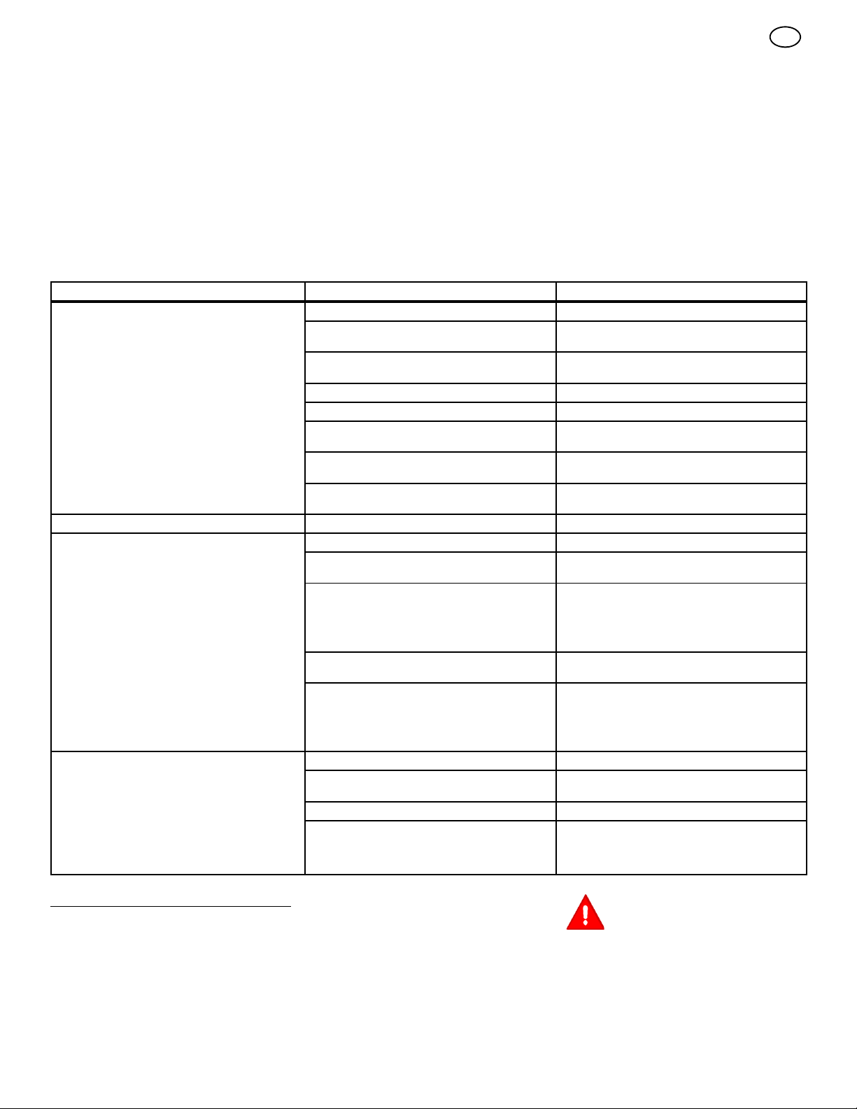
9. Se l’erba è molto alta, tagliarla due volte per
diminuire il carico del motore. Prima tagliare
con l’alloggiamento del tagliaerba sulla
posizione più alta, quindi abbassare
l’alloggiamento per il secondo taglio.
10.Per ottenere un miglior rendimento del
motore e uno scarico uniforme dell’erba
tagliata, usare sempre il motore con la
valvola a farfalla in posizione VELOCE.
11.Quando si usa un’insaccatrice, la valvola a
farfalla dovrebbe essere in posizione
VELOCE e il pedale di controllo della velocità
dovrebbe essere premuto per un terzo/metà.
12.Dopo ogni uso, pulire la parte inferiore e
superiore dell’alloggiamento del tagliaerba
per ottenere un rendimento ottimale. Inoltre
un alloggiamento del tagliaerba pulito aiuterà
a prevenire incendi.
TABELLA DI MANUTENZIONE
FREQUENZA OPERAZIONE COMMENTI
Ogni giorno o prima dell’uso Manutenzione del motore. Consultare il Manuale del motore.
Esaminare le lame. Controllare che non vi siano tagli, usura e danni
Rimuovere i detriti dall’unità e pulire da detriti il
tratto di prato che si intende tagliare.
Esaminare tutte le parti rotanti e scorrevoli.
Controllare la pressione dell’aria nei pneumatici. Consultare la sezione sulla Manutenzione.
Verificare che l’alloggiamento del tagliaerba sia
a livello.
Esaminare le cinghie a V. Controllare che non vi siano tagli, usura e danni
Controllare il funzionamento del freno. Consultare le sezioni sull’Uso ela
Al completamento delle prime 5 ore Cambiare l’olio. Consultare il Manuale del motore.
Dopo 25 ore Manutenzione del motore. Consultare il Manuale del motore.
Rimuovere, esaminare, affilare e bilanciare le
lame.
Controllare le regolazioni:
a. Controllo della rotazione della lama
b. Freno
c. Frizione
d. Sterzo
Lubrificare lo chassis e l’alloggiamento del
tagliaerba.
Controllare la marmitta:
a. Torsione
b. Verificare che non sia usurata o bruciata
c. Controllare le condizioni del dispositivo di
sicurezza (se applicabile).
Prima del rimessaggio di 30 giorni o più Preparare il motore per il rimessaggio. Consultare il Manuale del motore.
Drenare il sistema del combustibile. Consultare le avvertenze nel Manuale per
Aggiungere lo stabilizzatore di combustibile. Consultare il Manuale per l’uso.
Preparare la batteria per il rimessaggio:
a. Rimuoverla dall’unità.
b. Caricarla completamente.
c. Collocarla in un luogo fresco e asciutto.
eccessivi.
Consultare la sezione sulla Manutenzione.
eccessivi.
Manutenzione.
Consultare la sezione sulla Manutenzione.
Consultare la sezione sulla Manutenzione.
Consultare le istruzioni sui Punti da lubrificare.
Consultare la sezione sulla Manutenzione.
l’uso.
it
MANUTENZIONE
NOTA: le figure e i simboli iniziano a pagina 2.
Raccomandazioni generali
1. La manutenzione di questo prodotto è
responsabilità dell’acquirente. Essa
prolungherà la vita del prodotto ed è
necessaria per mantenere la validità della
garanzia.
2. Controllare la candela di accensione, il freno,
lubrificare l’unità e pulire il filtro dell’aria una
volta all’anno.
7102049
3. Controllare i dispositivi di fissaggio. Verificare
che siano ben stretti.
4. Seguire la sezione sulla Manutenzione per
mantenere l’unità in buone condizioni di
funzionamento.
21
ATTENZIONE: prima di
un’ispezione, regolazione, o
riparazione all’unità, scollegare il
filo dalla candela di accensione. Togliere il
filo dalla candela di accensione per evitare
che il motore dia origine a un incidente.
NOTA:latorsioneèmisuratainNm.Questa
misurazione indica fino a che punto deve
essere serrato un dado o un bullone. La
torsione viene misurata con una chiave
torsiometrica.
Page 22
Controllare la lama (Figura 7)
ATTENZIONE: prima di controllare
o togliere la lama, scollegare il filo
dalla candela di accensione. Se la
lama colpisce un oggetto, fermare il
motore. Controllare che l’unità non sia
danneggiata. La lama è affilata, indossare
guanti o usare un pezzo di tessuto per
proteggere le mani nel toccarla.
Se si mantiene affilata la lama (1) e si controlla
che non sia danneggiata, la lama taglierà meglio
e sarà più sicura. Controllare frequentemente
che la lama non sia troppo consumata, incrinata
o danneggiata in altro modo. Controllare
frequentemente il dado (3) che fissa la lama (1).
Mantenere il dado (3) ben stretto. Se la lama
colpisce un oggetto, arrestare il motore.
Scollegare il filo dalla candela di accensione.
Controllare che la lama non sia piegata o
danneggiata. Controllare che l’adattatore della
lama (5) non sia danneggiato. Prima di usare
l’unità, sostituire le parti danneggiate con parti
originali. Consultare il centro di assistenza
autorizzato locale. Ogni tre anni fare ispezionare
la lama o sostituire la vecchia lama con una
parte originale da un tecnico autorizzato.
Come togliere e installare la lama
(Figura 7)
1. Togliere l’alloggiamento del tagliaerba.
Vedere le istruzioni su “Come rimuovere
l’alloggiamento del tagliaerba:
2. Usare un pezzo di legno per impedire che la
lama giri.
3. Togliere il dado (3) che fissa la lama (1).
4. Controllare la lama (1) e l’adattatore della
lama (5) secondo le istruzioni contenute
nella sezione “Controllare la lama”. Sostituire
una lama consumata o danneggiata con una
lama originale. Consultare un centro
assistenza autorizzato locale.
5. Pulire la parte superiore e inferiore
dell’alloggiamento del tagliaerba. Eliminare
l’erba e i detriti.
6. Montare la lama (1) e l’adattatore della
lama (5) sul mandrino (6).
7. Montare la lama (1) in modo che i bordi di
sollevamento (7) siano verso l’alto. Se la
lama è capovolta, non taglierà correttamente
e può causare incidenti.
8. Fissare la lama (1) con la rondella e dado
originali (3). Verificare che il bordo esterno
della molla Belleville (2) sia contro la lama
(1).
ATTENZIONE: il dado (3) che fissa
la lama deve essere sempre ben
stretto (1). Un dado o una lama
allentanti possono causare un incidente.
9. Serrare il dado (3) che fissa la lama (1) con
una torsione di 41,5 Nm.
10.Installare l’alloggiamento del tagliaerba.
Vedere la sezione “Come rimuovere
l’alloggiamento del tagliaerba”.
7102049
Come regolare il comando di rotazione
della lama
ATTENZIONE: il comando di
rotazione della lama deve
funzionare correttamente per
prevenire lesioni.
In condizioni normali di uso, il comando di
rotazione della lama non richiederà regolazioni.
Tuttavia, se il rendimento peggiora o la qualità del
taglio è scadente, effettuare le seguenti modifiche.
1. Quando si taglia l’erba, verificare che il
comando della valvola a farfalla sia in
posizione VELOCE.
2. (Figura 8) Mettere il comando di rotazione
della lama in posizione DISINNESTO (1).
3. Spegnere il motore. Scollegare il filo dalla
candela di accensione.
4. Controllare la lama (o lame). Mantenerle
affilate. Una lama non af filata farà ingiallire
l’erba.
5. (Figura 9) Scollegare la molla di
azionamento della lama (2) dall’asta di
controllo della lama (1). Mettere la molla di
azionamento della lama (2) nel foro
centrale (4). In questo modo si diminuisce la
tensione sulla cinghia di trasmissione del
tagliaerba.
6. Collegare il filo alla candela di accensione.
Tagliare l’erba per un breve tratto e
ricontrollare la qualità del taglio. Se
necessario, spostare la molla di
azionamento della lama (2) sul foro
inferiore (5).
7. Ricontrollare la qualità del taglio. Se non è
migliorata, sostituire la cinghia di
trasmissione del tagliaerba. Vedere la
sezione “Come sostituire la cinghia di
trasmissione del tagliaerba”. Se sostituendo
la cinghia non si corregge il problema,
portare l’unità presso un centro di assistenza
autorizzato.
8. Mettere il comando di rotazione della lama in
posizione DISINNESTO. Fermare il motore.
9. (Figura 10) Controllare il funzionamento del
freno della lama. Girare a mano le puleggie.
Verificare che i cuscinetti del freno (1)
siano premuti fermamente contro le puleggie.
ATTENZIONE: se i cuscinetti del
freno (1) non premono fermamente
contro le pulegge, portare l’unità
presso un centro di assistenza autorizzato.
10.(Figura 8) Mettere il comando di rotazione
della lama in posizione INNESTO (2).
11. (Figura 10) Controllare i cuscinetti del freno
della lama (7). Se i cuscinetti sono
eccessivamente consumati o danneggiati,
sostituire i gruppi dei cuscinetti del freno. Parti
di ricambio corrette e assistenza sono
disponibili presso un centro di assistenza
autorizzato.
12.Collegare il filo alla candela di accensione.
Tagliare l’erba per un breve tratto e
ricontrollare il funzionamento del comando di
rotazione della lama.
22
it
13. Quando si mette il comando di rotazione della
lama in posizione DISINNESTO, ogni
movimento si interromperà entro cinque
secondi. Se la cinghia continua a muoversi o
le lame continuano a girare, innestare e
disinnestare il comando di rotazione della
lama cinque volte per eliminare la gomma in
eccesso della cinghia di trasmissione di un
nuovo tagliaerba. Per assistenza, portare
l’unità presso un centro di assistenza
autorizzato.
14.(Figura 9) Se si sostituisce la cinghia di
trasmissione del tagliaerba, spostare la
molla di azionamento della lama (2) nel
foro superiore (3).
Come controllare e regolare la cinghia
di trasmissione (Figura 18 e Figura 21)
Se la cinghia di trasmissione è allentata, la
cinghia slitta andando in salita, trainando un
carico pesante, o l’unità non andrà in avanti.
IMPORTANTE: usare sempre l’unità con il
motore in posizione VELOCE. Se il motore è
in posizione lenta o moderata, il motore e la
trasmissione possono riscaldarsi
eccessivamente e causare problemi simili a
quelli causati da una cinghia di trasmissione
allentata.
ATTENZIONE: prima di effettuare
un controllo, una regolazione, o di
riparare l’unità, scollegare il filo
dalla candela di accensione. Togliere il filo
dalla candela per evitare che il motore si
metta in funzione inavvertitamente.
1. (Figura 21) Controllare il percorso della
cinghia di trasmissione del movimento
(6). Assicurarsi che la cinghia di trasmissione del movimento (6) sia installata cor-
rettamente all’interno delle sue guide (7).
2. (Figura 18) Scollegare l’articolazione della
frizione (1) dal braccio della puleggia folle
(2).
3. (Figura 21) Allineare il foro nella leva del
freno (3) con il foro nel telaio. Mantenere
ferma la leva del freno (3) con un chiodino
o un bullone da 6 mm (4).
4. (Figura 18) Scollegare l’articolazione della
frizione (1) fino a quando il foro di montaggio (5) non sia allineato nel braccio della
puleggia folle (2).
5. Collegare l’articolazione della frizione (1)
al braccio della puleggia folle (2).
6. (Figura 21) Rimuovere il chiodino o bul-
lone da 6 mm (4).
7. Se la cinghia continua a slittare dopo la
regolazione della cinghia, significa che la
cinghia di trasmissione è consumata o
danneggiata e deve essere sostituita. Vedere
“Come sostituire la cinghia di trasmissione”.
Come controllare e regolare il freno di
guida (Figura12e20)
(Figura 20) Innestare il freno a mano. Spostare
il disinnesto automatico della trasmissione in
posizione SPINTA (3). Spingere l’unità. Se le
ruote posteriori girano, regolare o sostituire i
cuscinetti del freno.
Regolare il freno di trasmissione (4) nel seguente modo:
1. (Figura 12) Il freno di trasmissione (4) si
trova a destra della scatola degli ingranag-
gi (5).
Page 23
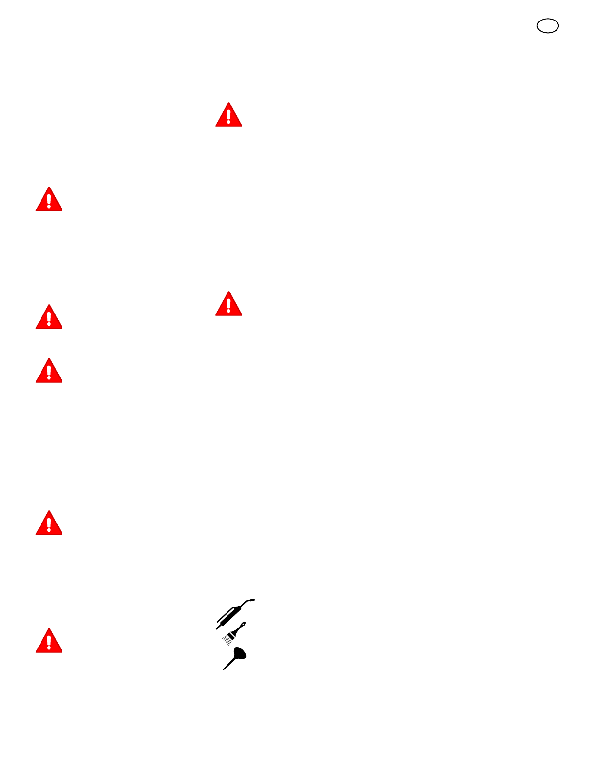
2. (Figura 20) Assicurarsi che il freno a mano
sia innestato e che il disinnesto automatico
della trasmissione (1) sia in posizione
SPINTA (3).
3. (Figura 12) Girare il dado esagonale (6) in
senso orario fino a quando le ruote non girano più quando l’unità viene spinta in avanti.
4. Rilasciare il freno a mano e spingere l’unità.
Se l’unità non si sposta, girare il dado
esagonale (6) in senso antiorario fino a
quando l’unità si sposta.
5. Mettere il freno a mano. Spingere l’unità. Se
le ruote posteriori non girano, il freno (4) è
regolato correttamente. Rilasciare il freno a
mano.
ATTENZIONE: se non si può
regolare correttamente il freno di
guida, sostituire i cuscinetti del
freno. Parti di ricambio corrette e
assistenza sono disponibili presso un
centro di assistenza autorizzato.
Come rimuovere la batteria (Figura 4)
Per caricare o pulire la batteria (1), togliere la
batteria (1) dall’unità nel modo seguente.
ATTENZIONE: per prevenire
scintille, scollegare il cavo nero
della batteria (8) dal terminale
negativo (--) prima di scollegare il cavo
rosso (5).
ATTENZIONE: la batteria contiene
acido solforico che è dannoso per
la pelle, gli occhi e gli indumenti.
Se l’acido entra in contatto con il corpo o
gli indumenti, lavare con acqua.
1. Scollegare il cavo nero (8) dal terminale
negativo (--).
2. Scollegare il cavo rosso (5) dal terminale
positivo (+) (4).
3. Sollevare il portabatteria (3) elabatteria (1)
dall’unità.
Come caricare la batteria (Figura 4)
ATTENZIONE: non fumare quando
si carica la batteria. Tenere la
batteria al riparo da scintille. Le
esalazioni acide della batteria possono
causare un’esplosione.
1. Prima di caricare la batteria (1), rimuoverla
dall’unità.
2. Per caricare la batteria (1), usare un
Caricabatterieda12volt.Caricarea6
ampere per un’ora.
3. Installare la batteria (1).
ATTENZIONE: per prevenire
scintille, fissare il cavo rosso al
terminale positivo (+) prima di
collegare il cavo nero.
4. Fissare il cavo rosso (5) al terminale
positivo (+) (4) con i dispositivi di fissaggio
come illustrato.
5. Fissare il cavo nero (8) al terminale
negativo (--) con i dispositivi di fissaggio
come illustrato.
7102049
Come regolare il livello
dell’alloggiamento del tagliaerba
(Figura 13 e Figura 14)
Se l’alloggiamento del tagliaerba è
perfettamente orizzontale, la lama taglierà
meglio e con migliori risultati estetici.
ATTENZIONE: prima di effettuare
un controllo, una regolazione, o di
riparare l’unità, scollegare il filo
dalla candela di accensione. Togliere il filo
dalla candela per evitare che il motore si
metta in funzione inavvertitamente.
1. Assicurarsi che l’unità sia su una superficie
dura e piatta.
2. Controllare la pressione dell’aria nei
pneumatici. Se la pressione dell’aria non è
corretta, l’alloggiamento del tagliaerba non
taglierà uniformemente. La giusta pressione
d’aria è di 0,97 BAR (14 PSI) per i
pneumatici anteriori, 0,69 BAR (10 PSI) per i
pneumatici posteriori.
3. (Figura 13) Spostare la leva di
sollevamento (1) sulla posizione di taglio
più bassa (2).
ATTENZIONE: la leva di
sollevamento (3) è caricata a molla.
Assicurarsi che la leva di
sollevamento (3) sia bloccata sulla
posizione di taglio più bassa (2).
4. (Figura 14) Allentare le manopole di
regolazione sinistra e destra (1). Premere
ciascun lato dell’alloggiamento del tagliaerba.
Assicurarsi che entrambi i lati
sull’alloggiamento del tagliaerba siano
appoggiati su una superficie piatta.Verificare
inoltre che gli anelli di sollevamento siano
allentati e che siano in grado di muoversi
liberamente verso l’alto e verso il basso.
5. Spingere verso il basso gli anelli di
sollevamento (2) e stringere le manopole
di regolazione (1) adestraeasinistra.
Accertarsi che le manopole di regolazione
(1) siano ben strette. Se necessario,
stringerle utilizzando una chiave.
6. (Figura 13) Sollevare la leva di
sollevamento (1).
7. Tagliare l’erba per un breve tratto. Se
l’altezza del taglio non è uniforme, ripetere le
fasi più sopra.
Dove effettuare la lubrificazione
(Figura 15)
I modelli con raccordi da
ingrassare: Usare una
pompa da ingrassaggio per
lubrificare.
Applicare il grasso con un
pennello sulle parti mostrate.
Lubrificare le parti mostrate
con olio per motore.
NOTA: applicare il grasso sul gruppo sterzo.
AVVERTENZA: se l’unità viene usata in zone
asciutte con sabbia, usare uno spray di
grafite secca per lubrificare l’unità.
23
it
Controllare i pneumatici
Controllare la pressione dell’aria nei pneumatici.
Pneumatici troppo gonfi sono duri,
compromettendo il comfort del trattore durante la
guida. Inoltre una pressione d’aria sbagliata
impedirà al tagliaerba di tagliare uniformemente.
La giusta pressione d’aria è di 0,97 BAR (14
PSI) per i pneumatici anteriori, 0,69 BAR (10
PSI) per i pneumatici posteriori.
Come sostituire la cinghia di
trasmissione del movimento
1. Rimuovere l’alloggiamento del tagliaerba.
Vedere le istruzioni su “Come rimuovere
l’alloggiamento del tagliaerba”.
2. (Figura 16) Rimuovere la puleggia folle
centrale (4).
3. Scollegare la molla della puleggia folle (7).
4. Rimuovere la puleggia folle (8) eildistan-
ziatore (9).
5. Rimuovere la puleggia folle a V (5) eildistanziatore (13).
6. Rimuovere la cinghia di trasmissione del
movimento (1) dalla puleggia motrice (6).
7. (Figura 17) Per rimuovere la cinghia di
trasmissione del movimento (1) dalla puleggia di scarico (2), tirare l’estremità ante-
riore della cinghia sotto la puleggia di
scarico (2) e quindi indietro fra la puleggia e
la piastra di guida (3).
8. (Figura 11) Rimuovere il pannello di acces-
so (10).
9. Rimuovere le due viti (11) che fissano il
gruppo della leva di guida (12). Alzare il
volante e il gruppo della leva di guida (12).
Tirare la cinghia di trasmissione del movi-
mento (1) sotto il gruppo della leva di
guida (12).
10.Rimuovere la cinghia di trasmissione del
movimento (1). Le corrette parti di ricambio
e assistenza sono disponibili presso il centro
di assistenza autorizzato di zona.
11.Per installare la cinghia di trasmissione, ripetere a ritroso le operazioni descritte qui
sopra.
12.(Figura 16) Controllare il percorso della
cinghia di trasmissione del movimento(1).
Verificare che la cinghia di trasmissione del
movimento sia installata correttamente sulle
pulegge folli.
13.Prima di usare l’unità, controllare la regolazione della frizione. Vedere le istruzioni
“Come controllare e regolare la frizione”.
14.Installare l’alloggiamento del tagliaerba. Vedere le istruzioni su “Come installare l’alloggiamento del tagliaerba”.
Come sostituire la cinghia di
trasmissione (Figura 10)
1. Rimuovere l’alloggiamento del tagliaerba.
Vedere la istruzioni su “Come rimuovere
l’alloggiamento del tagliaerba”.
2. Tirare il fermo della cinghia (1)
allontanandolo dalla puleggia folle (2) e
rimuovere la cinghia di trasmissione del
tagliaerba (3).
3. Tirare il fermo della cinghia (1)
allontanandolo dalla puleggia del mandrino
destro (5) e rimuovere la cinghia di
trasmissione del tagliaerba (3).
Page 24

4. Tirare il fermo della cinghia (4) lontano
dalla puleggia del mandrino sinistro (6) e
rimuovere la cinghia di trasmissione del
tagliaerba (3). La parte di ricambio corretta e
assistenza sono disponibili presso il centro
assistenza autorizzato più vicino.
5. Per installare la cinghia di trasmissione del
tagliaerba, ripetere a ritroso le fasi descritte
qui sopra.
Come rimuovere l’alloggiamento del
tagliaerba (Figura 22)
1. Mettere il comando di rotazione della lama
(1) in posizione DISINNESTO.
2. Spostare la leva di sollevamento (2) sulla
posizione di regolazione del livello.
La leva di sollevamento è a molla.
Assicurarsi che la leva di sollevamento sia bloccata nella posizione
REGOLAZIONE LIVELLO.
3. Rimuovere i chiodini e le rondelle dalle staffe
di regolazione (3). Vedere le illustrazioni “C”
e“D”.
4. Rimuovere i chiodini e le rondelle dagli anelli
di sospensione (4). Vedere le illustrazioni
“A” e “B”.
5. Scollegare la molla di allungamento (5)
dall’asta di controllo della lama (6). Vedere
l’illustrazione “E”.
6. Scollegare il supporto anteriore (9) dal
supporto dell’asse. Vedere l’illustrazione “F”.
7. Togliere la cinghia di trasmissione del
tagliaerba (7) dalla puleggia di scarico (8).
8. Allontanare l’alloggiamento del tagliaerba dal
lato destro dell’unità.
9. Per installare l’alloggiamento del tagliaerba,
ripetere a ritroso le fasi descritte qui sopra.
it
Come ordinare pezzi di ricambio
I pezzi di ricambio sono mostrati nelle ultime
pagine di questo libretto di istruzioni o in un
libretto apposito.
Usare solamente pezzi di ricambio autorizzati o
approvate dal fabbricante. Non usare accessori
non specificamente raccomandati per questa
unità. Per ottenere i pezzi di ricambio corretti, si
deve indicare il numero di catalogo del
tagliaerba (vedere la targhetta).
I pezzi di ricambio, tranne il motore, la
trasmissione, il gruppo cambio differenziale
posteriore, il differenziale, sono disponibili
presso il negozio in cui è stato acquistato il
tagliaerba o presso un negozio specializzato da
esso raccomandato.
L’assistenza in garanzia è disponibile esclusivamente presso i Centri di Assistenza Autorizzati,
che potete trovare con il nostro Dealer Locator
all’indirizzo www.murray.com.
I pezzi di ricambio per il motore, la trasmissione,
il gruppo cambio differenziale posteriore, il
differenziale, sono disponibili presso il centro
assistenza elencato nella sezione commerciale
della rubrica telefonica. Vedere inoltre le
garanzie individuali per il motore o la
trasmissione per ordinare pezzi di ricambio.
Per ordinare sono necessarie le seguenti
informazioni:
(1) Numero di modello
(2) Numero di serie
(3) Numero di catalogo
(4) Quantità
Come sostituire il fusibile
Se il fusibile brucia, il motore non partirà.
Rimuovere il fusile e sostituirlo con un fusibile
per autoveicoli da 15 amp.
Conservazione (oltre 30 giorni)
Alla fine dell’anno, preparare l’unità per la
conservazione nel modo seguente.
1. Svuotare la benzina dal carburatore e dal
serbatoio. Cambiare l’olio del motore.
Consultare le istruzioni del fabbricante del
motore.
2. Pulire l’intera unità.
3. Caricare la batteria.
7102049
24
Page 25

SOLUZIONE DI PROBLEMI
PROBLEMA: il motore non si avvia.
1. Seguire le istruzioni della sezione “Come avviare il motore” di questo libretto.
2. Modelli ad avviamento elettrico: pulire i terminali della batteria. Stringere i cavi.
3. Controllare che non vi sia un filo allentato.
Serrare gli interruttori di fine corsa (vedere il
diagramma del cablaggio).
4. Svuotare il serbatoio di benzina. Pulire il tubo
di alimentazione. Sostituire il filtro del carburante.
5. Rimuovere la candela (o candele) di accensione. Mettere la valvola a farfalla in posizione LENTO. Girare la chiave di accensione
sulla posizione ON. Provare ad avviare il motore diverse volte. Installare la candela di accensione.
6. Sostituire la candela.
7. Regolare il carburatore.
PROBLEMA: Il motore non si ribalta.
1. Seguire le istruzioni della sezione “Come avviare il motore” di questo libretto.
2. Modelli ad avviamento elettrico: Caricare la
batteria.
3. Sostituire il fusibile.
4. Controllare che la filatura non sia danneggiata o un connettore non sia allentato. Riparare
il filo danneggiato.
5. Modelli ad avviamento elettrico: sostituire il
solenoide. Modelli ad avviamento autoavvolgente: sostituire il modulo.
PROBLEMA: il motore si avvia con
difficoltà.
1. Regolare il carburatore.
2. Sostituire la candela di accensione.
3. Sostituire il filtro del carburante.
PROBLEMA: il motore non gira
uniformemente o perde potenza.
1. Controllare l’olio.
2. Pulire il filtro dell’aria.
3. Pulire lo schermo dell’aria.
4. Sostituire la candela di accensione.
5. Il motore è sottoposto a sforzo eccessivo.
Usare una marcia più bassa.
6. Regolare il carburatore.
7. Sostituire il filtro del carburante.
PROBLEMA: il motore non gira
uniformemente ad alta velocità.
1. Sostituire la candela di accensione.
2. Regolare il comando della valvola a farfalla.
3. Pulire il filtro dell’aria.
4. Sostituire il filtro del carburante.
PROBLEMA: il motore si ferma quando
le lame sono innestate.
1. Controllare che la filatura non sia danneggiata o non vi sia un connettore allentato. Riparare il filo danneggiato.
2. Occorre installare il raccoglierba (pertinente
solamente per i modelli con raccoglierba a
scarico posteriore d’erba).
PROBLEMA: il motore si ferma su
pendenze.
1. Tagliare l’erba in senso longitudinale sulla
pendenza. Non tagliare mai l’erba attraverso
una pendenza.
PROBLEMA: il motore non gira al
minimo.
1. Sostituire la candela di accensione.
2. Pulire il filtro dell’aria.
3. Regolare il carburatore.
4. Regolare il comando della valvola a farfalla.
5. Svuotare il serbatoio di benzina. Pulire il tubo
di alimentazione. Sostituire il filtro del carburante.
PROBLEMA: quando il motore è caldo si
verifica una diminuzione della potenza.
1. Pulire il filtro dell’aria.
2. Controllare l’olio.
3. Regolare il carburatore.
4. Sostituire il filtro del carburante.
PROBLEMA: vibrazione eccessiva.
1. Sostituire la lama.
2. Controllare che i bulloni della lama non siano
allentati.
3. Diminuire la pressione dell’aria nei pneumatici.
4. Regolare il carburatore.
5. Controllare che la cinghia o la puleggia non
siano danneggiate. Sostituire le parti danneggiate.
PROBLEMA: l’erba non viene scaricata
correttamente.
1. Fermare il motore. Pulire l’alloggiamento del
tagliaerba.
2. Alzare l’altezza del taglio.
3. Sostituire o affilare la lama (o lame).
4. Mettere la leva del cambio su una marcia più
bassa.
5. Spostare il comando della valvola a farfalla
sulla posizione VELOCE.
6. Sostituire la molla della puleggia folle della
lama.
it
7. Pulire il tubo di prolunga e il tubo di collegamento (pertinente solamente per i modelli
con raccoglierba a scarico posteriore d’erba).
PROBLEMA: l’alloggiamento del
tagliaerba non taglia uniformemente.
1. Controllare la pressione dell’aria nei pneuma tici.
2. Regolare il livello dell’alloggiamento del tagliaerba.
3. Controllare l’asse anteriore. Se l’asse anteriore non ruota liberamente, allentare il bullone (o bulloni) dell’asse.
PROBLEMA: le lame del tagliaerba non
ruotano.
1. Controllare la cinghia di trasmissione del tagliaerba. Verificare che sia installata correttamente.
2. Sostituire la cinghia di trasmissione del tagliaerba.
PROBLEMA: l’unità non si sposta
quando il freno viene rilasciato e si
preme il pedale di controllo della
velocità.
1. Controllare la cinghia di trasmissione del movimento. Verificare che sia installata correttamente.
2. Regolare la frizione.
3. Sostituire la cinghia di trasmissione del movimento.
4. Rilasciare il disinnesto automatico della trasmissione che si trova sotto il sedile.
PROBLEMA: quando si preme il pedale
di controllo della velocità l’unità si
sposta lentamente o si ferma.
1. Regolare la frizione.
2. Sostituire la cinghia di trasmissione del movimento.
PROBLEMA: quando il pedale del freno
viene rilasciato, si può sentire il rumore
della cinghia.
1. Se la cinghia fa rumore temporaneamente, il
funzionamento dell’unità non viene compromesso. Se il rumore è continuo, controllare il
percorso della cinghia. Verificare che la cinghia si trovi all’interno di tutte le relative guide.
2. Se il rumore è continuo, regolare la frizione.
PROBLEMA: le ruote posteriori girano
su terreno accidentato.
1. Controllare l’asse anteriore. Se l’asse anteriore non ruota liberamente, allentare il bullone (o bulloni) dell’asse.
7102049
25
Page 26

INHOUD
INTERNATIONALE PICTOGRAMMEN 26
GARANTIEBEPALINGEN 27
INFORMATIE VOOR DE EIGENAAR 28
VEILIGE BEDIENING 28
MONTAGE 29
BEDIENING 30
ONDERHOUDSSCHEMA 32
ONDERHOUD 32
TROUBLESHOOTING SCHEMA 35
nl
INTERNATIONALE PICTOGRAMMEN
BELANGRIJK: De volgende pictogrammen
bevinden zich op uw machine of in de daarbijbehorende literatuur. Voordat u de machine gaat bedienen, moet u de betekenis en het
doel van elk pictogram leren begrijpen.
OPMERKING: Illustraties en
pictogrammen beginnen op pagina 2.
Veiligheids- en waarschuwings-pictogrammen (Figuur 23)
1 Waarschuwing.
2 BELANGRIJK: Lees de gebruiksaanwijzing
voordat u deze machine gaat bedienen.
3 WAARSCHUWING: Uitgeworpen
voorwerpen. Houdt omstanders op afstand.
Lees de gebruiksaanwijzing voordat u deze
machine gaat bedienen.
4 WAARSCHUWING: Gebruik deze machine
niet op hellingen van meer dan 10 graden.
5 GEVAAR: Houdt omstanders en vooral
kinderen uit de buurt van de machine.
6 GEVAAR: Dit is geen trede.
7 GEVAAR: Houd voeten en handen uit de
buurt van draaiende messen.
9 GEVAAR: Verwijder de bougiekabel van de
bougie voordat u onderhoud aan de
machine uitvoert.
10 WAARSCHUWING: Heet oppervlak.
11 WAARSCHUWING: Wees voorzichtig bij
het aansluiten en loskoppelen van
accessoires.
12 WAARSCHUWING: Vingers kunnen
bekneld raken.
13 BELANGRIJK: Volg de instructies in de
Handleiding om het maaibehuizing
horizontaal te zetten.
14 WAARSCHUWING: zolang de motor draait,
dient u uit de buurt van het mes blijven.
Bedieningspictogrammen
(Figuur 24)
1 Starten van de motor
2 Lichten
3 Laten draaien van de motor
4 Stoppen van de motor
5 Laten draaien van de motor
6 Rem
7 Handrem
8 Koppeling
9 Langzaam
10 Snel
11 Choke
12 Olie
13 Bediening mesrotatie
14 Omhoog brengen
15 Brandstof
7102049
26
Page 27

nl
BRIGGS & STRATTON CORPORATION EIGENAAR GARANTIEPOLITIEK
Geldig vanaf 1 januari 2006, vervangt alle ongedateerde Garanties en alle Garanties gedateerd vóór 1 januari 2006.
GARANTIEBEPALINGEN
Briggs & Stratton zal zonder berekening elk onderdeel, of onderdelen van het product vervangen dat defect is in materiaal of bewerking of beide.
Transportkosten voor producten die zijn ingezonden voor reparatie of vervanging met betrekking tot deze garantie komen ten laste van de koper.
Deze garantie heeft betrekking op de tijdsduur en is onderhevig aan de hieronder afgedrukte voorwaarden. Voor garantieservice dient U de
dichtstbijzijnde Geautoriseerde Service Dealer te vinden in onze “dealer locator” kaart op www.murray.com.
ER IS GEEN ANDERE EXPLICIETE GARANTIE. INBEGREPEN GARANTIES, INCLUSIEF DIE VAN VERKOOPBAARHEID EN
GESCHIKTHEID VOOR EEN BEPAALD DOEL ZIJN BEPERKT TOT ÉÉN JAAR VANAF AANKOOP, OF TOT DIE OMVANG DIE DOOR DE WET
IS TOEGESTAAN. ALLE INBEGREPEN GARANTIES ZIJN UITGESLOTEN. AANSPRAKELIJKHEID VOOR INCIDENTELE- OF
GEVOLGSCHADES ZIJN UITGESLOTEN VOOR ZOVER DEZE UITSLUITING WETTIG IS TOEGESTAAN. Sommige rechtsgebieden staan
geen beperking toe met betrekking tot hoe lang inbegrepen garantie duurt, en sommige rechtsgebieden staan geen uitsluiting toe met betrekking
tot incidentele- of gevolgschades, dus de bovenvermelde beperkingen en uitsluitingen kunnen mogelijk niet op U van toepassing zijn. Deze
garantie geeft U bepaalde specifieke rechten en U kunt mogelijk andere rechten hebben die van rechtsgebied tot rechtsgebied variëren.
GARANTIE TERMEN
Merk / Unit Gebruik Gebruik Garantie Termijn
Zitmaaiers / Tractors 2 jaar 90 dagen.................. .............
De garantieperiode begint op de dag van aankoop van de eerste detailhandelconsument of commerciële eindgebruiker en gaat door voor
de tijdsperiode in bovenstaande tabel. “Consumentengebruik” betekent persoonlijk huishoudelijk gebruik door een detailhandelconsument.
“Commercieel gebruik” betekent elk ander gebruik, inclusief inkomen verschaffend gebruik of verhuurdoeleinden. Als een product eenmaal
commercieel gebruikt is, dan zal deze daarna voor deze garantie als commercieel gebruikt worden beschouwd.
Er is geen garantieregistratie nodig om garantie te verkrijgen op Murray producten. Bewaar uw aankoopnota. Indien u geen bewijs van de
eerste aankoopdatum kunt overleggen op het moment dat om garantieservice verzocht wordt, dan zal de fabricagedatum van het product
gebruikt worden om de garantieperiode te bepalen.
Consument Commercieel Omstandigheid van
OVER UW GARANTIE
Wij verwelkomen garantiereparatie en verontschuldigen ons voor het ongemak. Elke geautoriseerde Service Dealer kan
garantiereparaties uitvoeren. De meeste garantiereparaties zullen routinematig worden uitgevoerd, maar soms kunnen verzoeken om
garantieservice niet gerechtvaardigd zijn. Bijvoorbeeld, garantieservice is niet van toepassing indien de schade aan het product het
gevolg is van misbruik, gebrek aan routinematig onderhoud, verzending, behandeling, opslag of verkeerde installatie. Evenzo is
garantie ongeldig indien het serienummer van het product verwijderd is of indien het product gewijzigd of gemodificeerd is.
Deze garantie dekt uitsluitend met het product verbandhoudende materialen. Om misverstanden die tussen dealer en klant kunnen
ontstaan te voorkomen, zijn hieronder enkele oorzaken van het defect raken van een product opgenoemd die niet onder garantie
worden gedekt.
• Normale Slijtage: Door kleine motoren aangedreven machines hebben, net als alle mechanische apparaten, periodiek onderhoud en vervanging
van onderdelen nodig om goed te presteren. Garantie dekt geen reparaties wanneer normaal gebruik de levensduur van het product of onderdeel
heeft uitgeput.
• Installatie: Deze garantie is niet van toepassing op producten die onderhavig zijn geweest aan verkeerde of niet geautoriseerde installatie, veran-
dering of modificatie. Noch installaties die starten voorkomen of onbevredigende motorprestaties veroorzaken.
• Verkeerd Onderhoud: De levensduur van deze machine hangt af van de omstandigheden waaronder deze werkt, evenals het onderhoud dat wordt
uitgevoerd. Aanbevolen onderhoud en afstelintervallen zijn afgedrukt in de Gebruiksaanwijzing. Vaak worden producten zoals grondfrezen, kantenmaaiers en cirkelmaaiers gebruikt in stoffige omstandigheden, waardoor wat lijkt op voortijdige slijtage kan optreden. Zulke slijtage, indien veroorzaakt door stof, vuil of ander schurend materiaal dat het product kan binnendringen door verkeerd onderhoud, wordt niet door garantie gedekt. De
garantie zal geen reparaties dekken die het gevolg zijn van vervangingsonderdelen die niet-origineel geproduceerde onderdelen zijn.
• Verkeerde en/of onvoldoende brandstof of smering: Deze garantie dekt geen schade door het gebruik van verouderde brandstof, of gemanipu-
leerde benzines. Schade aan de motor of motorcomponenten, zoals verbrandingskamer, kleppen, klepzetels, klepgeleiders, verbrande startmotorwikkelingen veroorzaakt door alternatieve brandstoffen zoals LPG, aardgas, worden niet gedekt tenzij de motor hiervoor is gecertificeerd. Onderdelen die zijn ingelopen of gebroken doordat het product was gebruikt met onvoldoende, vervuilde of de verkeerde kwaliteit smeerolie, evenals productcomponenten die zijn beschadigd door onvoldoende smering zijn niet gedekt.
• Misbruik tijdens gebruik: Het correcte gebruik van het product is vermeld in de gebruiksaanwijzing. Producten die beschadigd zijn door over toe-
ren draaien, oververhitting, of gebruik in een afgesloten ruimte zonder voldoende ventilatie, producten die defect geraakt zijn door overmatige trillingen door een losse motorbevestiging, losse of niet-gebalanceerde messen, aandrijvingen, over toeren draaien, of een kromme krukas door het
raken van een vast voorwerp, schade of storing ten gevolge van ongelukken, misbruik of verkeerde service of verstarring of chemische vervorming,
evenals gebruik buiten de aanbevolen capaciteiten als aangegeven in de gebruiksaanwijzing wordt niet gedekt.
• Routinematig onderhoud, slijtdelen of afstellingen: Deze garantie sluit slijtdelen zoals olie, snaren, messen, O-ringen, filters enz. uit.
• Overige uitsluitingen: Reparatie of afstellingen voor onderdelen die niet zijn gefabriceerd door de Briggs & Stratton Corporation, zijn niet gedekt,
raadpleeg de garantie voor de betreffende fabrikanten. Deze garantie sluit defecten uit die het gevolg zijn van natuurrampen en andere overmacht die niet binnen de macht van de fabrikant ligt. Ook zijn gebruikte, gereviseerde en demonstratieproducten uitgesloten.
Garantieservice is uitsluitend beschikbaar via Geautoriseerde Servicedealers. U kunt uw dichtstbijzijnde dealer vinden in onze “locator
map” bij www.murray .com.
7102049
27
Page 28
INFORMATIE VOOR DE
EIGENAAR
Ken uw machine: Als u de machine en de werking ervan
begrijpt krijgt u de beste resultaten. Vergelijk de illustraties
van de machine met de werkelijkheid, terwijl u deze handleiding doorleest. Leer de werking van de bedieningselementen en waar ze zich bevinden. Volg de
bedieningsaanwijzingen en de veiligheidsregels om een
ongeluk te voorkomen. Bewaar deze handleiding om hem
later te kunnen raadplegen.
WAARSCHUWING: Let op! Dit symbool duidt op belangrijke veiligheidsmaatregelen. Dit symbool betekent: “Let en pas op! Uw veiligheid kan in gevaar
zijn.”
Verantwoordelijkheid van de eigenaar
WAARSCHUWING: Dit is een snijdende
machine die in staat is handen en voeten te
amputeren en voorwerpen weg te slingeren. Veronachtzaming van de volgende veiligheidsaanwijzingen kan resulteren in ernstig letsel of de
dood voor de bestuurder en omstanders.
Het is de verantwoordelijkheid van de eigenaar om de
onderstaande aanwijzingen op te volgen.
VEILIGE BEDIENING
Voor rijdende zitmaaiersmet
roterende messen
Training
1. Lees de instructies nauwkeurig. Wees vertrouwd met
de bediening en het juiste gebruik van de machine.
2. Sta nooit toe dat kinderen of mensen die niet bekend
zijn met deze instructies de machine gebruiken. Lokale regels kunnen een minimum leeftijd voor de
bestuurder voorschrijven.
3. Maai nooit als er omstanders, in het bijzonder kinderen, of huisdieren in de buurt zijn.
4. Onthoud dat de bestuurder of gebruiker verantwoordelijk is voor ongevallen of blootstelling aan gevaar
aan derden of hun bezittingen.
5. Neem nooit passagiers mee.
6. Alle bestuurders moeten ervoor zorgen dat ze professionele en practische instructie krijgen. Zulke instructie moet de nadruk leggen op:
a. de noodzaak voor behoedzaamheid en con-
centratie bij het werken met zitmaaiers;
b. de controle over de machine die gaat glijden
op een helling kan niet worden herkregen door
de rem te gebruiken. De belangrijkste redenen
voor het verliezen van controle zijn:
• onvoldoende grip op de wielen;
• te snel rijden;
• verkeerd remmen;
• het soort maaier is ongeschikt voor de
taak;
• onbekendheid met de grondcondities, in
het bijzonder hellingen;
• verkeerd optrekken en verkeerde ladingsverdeling.
Voorbereiding
1. Draag tijdens het maaien altijd stevige schoenen en
7102049
een lange broek. Bedien de machine niet met blote
voeten of met sandalen aan.
2. Onderwerp het te maaien gebied aan een grondige
inspectie en verwijder alle voorwerpen die door de
machine uitgeworpen zouden kunnen worden.
3. WAARSCHUWING: Benzine is zeer brandbaar.
a. Bewaar brandstof incontainers die speciaal
voor dit doel ontworpen zijn
b. Voeg benzine toe in de frisse lucht en rook
niet.
c. Voeg benzine toe voordat u de motor aanzet.
Verwijder nooit de benzine tankdop of voeg
benzine toe terwijl de motor loopt of nog heet
is.
d. Als er benzine gemorst is, mag u de motor niet
starten, maar moet u de machine van de plek
met de gemorste benzine verwijderen en voorkomen dat er een vonk kan optreden, totdat de
benzine verdampt is.
e. Schroef alle doppen van benzine containers en
tanks zorgvuldig vast.
4. Vervang defecte geluidsdempers.
5. Controleer voor gebruik altijd dat de messen, mesbouten en snijconstructie niet versleten of beschadigd zijn.
Vervang versleten of beschadigde bladen en bouten in
paren zodat het evenwicht niet verstoord wordt.
6. Bij machines met meerdere bladen kan het draaien
van één blad tot gevolg hebben dat andere bladen
ook gaan bewegen.
Bediening
1. Gebruik de machine niet in een afgesloten ruimte,
waar zich gevaarlijke koolmonoxyde dampen kunnen
ophopen.
2. Maai alleen bij daglicht of goed kunstlicht.
3. Voordat u de motor start, moet u alle mesassesoires
loskoppelen en de koppeling in de neutrale stand
zetten.
4. Gebruik de machine niet op hellingen van meer dan
10_.
5. Onthoud dat er geen “veilige” hellingen bestaan. Het
rijden over grashellingen vraagt om speciale aandacht. Om omkantelen te voorkomen, moet u:
a. niet plotseling stoppen of optrekken, terwijl u
omhoog of omlaag rijdt;
b. de koppeling langzaam op laten komen en de
motor altijd in de versnelling laten, vooral wanneer u de helling af rijdt;
c. langzaam rijden op hellingen en in scherpe
bochten;
d. oppassen voor hobbels, kuilen en andere ver-
borgen gevaren;
e. nooit loodrecht op hellingsrichting rijden, tenzij
de maaier voor dit doel ontworpen is.
6. Pas op bij het trekken van ladingen of het gebruiken
van zwaar materieel.
a. Gebruik alleen de daarvoor bestemde trekha-
ken.
b. Vervoer alleen ladingen die u kunt beheersen.
c. Maak geen scherpe bochten. Pas op bij het
achteruit schakelen.
d. Gebruik tegengewichten of gewichten aan de
wielen als dat in het Instructieboek wordt aan-
geraden.
7. Let op het andere verkeer bij het oversteken van
wegen.
8. Zet het roteren van de messen af voordat u over iets
anders dan gras rijdt.
9. Als u assessoires gebruikt, let er dan op dat er nooit
materiaal in de richting van omstanders geslingered
28
nl
wordt. Laat nooit iemand in de buurt van de machine
als deze aan het werken is.
10. Bedien de maaier nooit als de beschermkappen kapot zijn. De beschermkappen moeten altijd op hun
plaats zitten.
11. Verander de instellingen van de regulateur van de
machine niet en voer hem niet op. Het gebruiken van
een machine bij te hoge snelheid kan de kans op
gevaar of persoonlijk letsel vergroten.
12. Voordatu van de bestuurdersplaats afstapt, moet u
a. de motor ontkoppelen en de assessoires laten
zakken;
b. de motor in de neutrale stand zetten en de
handrem aantrekken;
c. de motor afzetten en het contactsleuteltje ver-
wijderen.
13. Ontkoppel de assessoires, stop de motor en trek de
bougiekabel(s) los of verwijder het contactsleuteltje,
voordat u
a. verstoppingen in de trechter of elders verhelpt;
b. de maaier controleert, reinigt of er aan wilt
werken;
c. de maaier inspecteert nadat u een obstakel
geraakt hebt. Voer, indien nodig, reparaties uit
voordat u de machine opnieuw start en gebruikt;
d. de motor controleert bij abnormaal trillen. (On-
middellijk stoppen.)
14. Koppel de assessoires los als u de maaier niet gebruikt of deze wilt transporteren.
15. Zet de motor af en ontkoppel de assessoires voorat
u
a. bezine bijvult;
b. de grasopvanger verwijdert;
c. de hoogte aanpast, tenzij dat vanaf de bes-
tuurdersplaats kan gebeuren.
16. Neem gas terug aan het einde van de maaiactiviteiten. Draai de benzinekraan dicht, indien de motor
hiermee is uitgerust.
17. Voordatu achteruit rijdt, moet u naar achteren en
beneden kijken om u ervan te vergewissen dat er
geen kleine kinderen in de buurt zijn.
18. Wees extra voorzichtig bij blinde hoeken, struiken,
bomen of andere obstakels die het zicht kunnen
wegnemen.
Onderhoud en opslag
1. Bij machines met meerdere messen kan het bewegen
van één mes de andere messen ook inbeweging zetten. Wees voorzichtig!
2. Als u de machine parkeert of weg zet, moet u het
snijgedeelte van de machine laten zakken tenzij u
het stut of vast zet.
3. Zorg ervoor dat alle moeren, bouten en schroeven
vast aangedraaid zitten om er zeker van te zijn dat
de machine in veilige staat verkeert.
4. Parkeer de machine nooit met benzine in de tank, in
een afgesloten ruimte waar de dampen met een
vlam of vonk in aanraking kunnen komen.
5. Laat de motor afkoelen voorat u de machine in een
afgesloten ruimte weg zet.
6. Verwijder gras, bladeren en overmatig smeervet van de
geluidsdemper, het accucompartiment en van de benzine opslagplaats om gevaar voor brand te verminderen.
7. Comtroleer de grasvanger regelmatig op slijtage.
8. Vervang versleten of beschadigde onderdelen om
veiligheidsredenen.
9. Als het nodig blijkt de benzinetank af te tappen, moet
dit in de frisse lucht gebeuren.
Page 29
MONTAGE
e
-
k
Alle bevestigingsmaterialen zitten in de zak met
onderdelen. Gooi geen onderdelen of materiaal
weg voordat de maaier inelkaar gezet is.
WAARSCHUWING: Voordat u aan
de maaier werkt, moet u de bougiekabel lostrekken.
OPMERKING: In deze handleiding zijn de termen links en rechts gebruikt vanuit het gezichtspunt van de berijder.
OPMERKING: Illustraties en pictogrammen
beginnen op pagina 2.
OPMERKING: De bevestigingsmaterialen die
u moet gebruiken om de volgende losse
onderdelen te monteren, zijn op ware grootte
weergegeven in figuur 25.
Installeren van de voorwielen (Figuur 1)
Geruik een mes om de vier kanten van de container open te snijden. Plaats de voorwielen (1)
in de container.
OPMERKING: Gebruik een blok hout van ongeveer 1,25 m. lang om de voorkant van de
tractor omhoog te brengen. Als er geen hout
aanwezig is kan iemand anders helpen om
de tractor op te tillen. Pas op dat de tractor
niet valt.
1. Til de voorkant van de tractor op en leg het
blok hout onder de tractor.
2. Zorg ervoor dat het ventiel (2) aan de buitenkant komt te zitten. Schuif het voorwiel
op de as (3).
3. Maak beide voorwielen vast met een ring
(4) en splitpen (5). Buig de einden van de
splitpen (5) om, zodat het voorwiel niet van
de as (3) afglijden kan.
4. Als de voorwielen geïnstalleerd zijn mag u
de tractor van het blok hout tillen en uit de
container duwen.
5. Plaats de wieldoppen (6), indien uw tractor
daarmee uiterust is. Zorg ervoor dat de rin-
gen (4) de wieldoppen (6) op hun plaats
houden.
Installeren van de bestuurdersstoel
(Figuur 2)
1. Verwijder voorzichtig de plastic zak van de
bestuurdersstoel (1).
2. Plaats de gaten in de stoelscharnier (2) en
de gaten in de stoel (1) over elkaar. Bevestig
de stoel (1) aan de stoelscharnier (2) met
de bevestigingsmaterialen (4) en (5).
3. Controleer de stand van de stoel (1). Maak
de twee vleugelmoeren (5) los indien de
stoel (1) ingesteld moet worden. Schuif de
stoel (1) naar voren of achteren via de stoelinstelgaten (3). Maak de vleugelmoeren
(5) weer vast.
Montage van het stuurwiel (Figuur 3)
1. Zorg ervoor dat de voorwielen recht staan.
2. Schuif de kap (3) over de stuurstang (2).
Zorg ervoor dat de uitstekende rand van de
kap (3) aan de bovenkant zit.
3. Schuif het stuurwiel (1) op de stuurstang
(2).
4. Maak het stuurwiel (1) vast aan de stuurstang (2) met schroef (4) en ringetje (6).
5. Sommige modellen hebben een optioneel
plaatje (7) voor het stuurwiel in de zak met
onderdelen. Bevestig het plaatje (7) in het
midden van het stuurwiel (1).
Onderhoudsvrije accu (Figuur 4)
BELANGRIJK: Controleer de datum op de
accu voordat u de accukabels bevestigt.
Deze datum geeft aan of de accu opgeladen
moet worden.
1. De datum van de accu staat boven en op de
zijkant van de accu (1).
2. Als de datum later is dan vandaag, hoeft de
accu (1) niet opgeladen te worden en kunnen de accukabels bevestigd worden. Zie
“Installeren van de accukabels”.
3. Als de datum vroeger is dan vandaag, moet
de accu (1) opgeladen worden. Zie “Opladen
van een onderhoudsvrije accu”.
Opladen van de accu (Figuur 4)
WAARSCHUWING: Rook niet tijdens
het opladen van de accu. Houd de
accu uit de buurt van vonken. De
dampen van het accuzuur kunnen een explosie veroorzaken.
1. Verwijder de accu (1) en accubak (3).
2. Verwijder de kap van de pol.
3. Gebruik een acculader van 12 Volt om de
accu op te laden (1). Laadt de accu op gedurende 1 uur onder 6 Ampère. Als u geen acculader heeft, moet u de accu door een
erkend service center laten opladen.
4. Installeer de accu (1) en accubak (3). Zorg
ervoor dat de positieve (+) pool (4) aan de
linker kant komt te zitten.
nl
Installeren van de accukabels (Figuur 4)
WAARSCHUWING: Om vonken te
voorkomen, moet u de rode kabel m
de positieve (+) pool verbinden voor
dat u de zwarte kabel aansluit.
1. Verwijder de kap van de accupol.
2. Schuif het poolkapje (2) op de rode kabel
(5). Bevestig de rode kabel (5) aan de positieve (+) pool (4) met de bevestiginsmaterialen (6) en (7).
3. Bevestig de zwarte kabel (5) aan de negatieve (--) pool met de bevestiginsmaterialen (6) en (7).
Controleer de banden
Controleer de bandenspanning. Banden met te
veel lucht hebben tot gevolg dat de machine ruw
rijdt. De verkeerde bandenspanning zal verder tot
gevolg hebben dat de maaier onregelmatig maait.
De juiste bandenspanning is: voor 0,97 BAR (14
PSI), achter 0,69 BAR (10 PSI). Voor verscheping waren de banden extra opgepompt.
Controleer de hoogte van de behuizing
Controleer of de maaihoogte gelijkmatig is. Maai
een kort stukje en kijk naar het gemaaide oppervlak. Als de maaier niet egaal maait, volg dan de
instrukties onder “Richten van de maaierbehuizing” in het hoofdstuk Onderhoud en Afstellen
van deze handleiding.
In gereedheid brengen van de motor
OPMERKING:Demotorwasindefabriekmet
olie gevuld. Controleer het oliepeil en vul
eventueel olie bij.
Zoek in de handleiding van de motorfabrikant op
welk soort benzine en olie u moet gebruiken.
Lees eerst de informatie over veiligheid, bediening, onderhoud en opslag.
WAARSCHUWING: Zoek in de handleiding van de motorfabrikant op wel
soort benzine en olie u moet gebruiken. Gebruik altijd een goedgekeurde jerrycan. Rook niet tijdens het bijvullen van benzine. Zet de motor af en laat deze eerst enige
minuten afkoelen. Bijvullen van benzine mag
nooit in afgesloten ruimtes gebeuren.
Belangrijk! Voor het maaien moet u:
U de motorolie peilen,
U de tank met benzine vullen,
U de bandenspanning controleren,
U de stand van de maaibehuizing
controleren,
U de accukabels bevestigen.
7102049
29
Page 30
BEDIENING
OPMERKING: Illustraties en pictogrammen
beginnen op pagina 2.
Plaats van de bedieningselementen
(Figuur 5) (Figuur 20)
Bediening van de mesrotatie (1): Gebruik om
de mesrotatie in werking te zetten en te stoppen.
Rempedaal (2): Gebruik het rempedaal om snel
te stoppen.
Lichtschakelaar (3): De lichtschakelaar is het
eerste gedeelte van de ontstekingsschakelaar.
Draai, terwijl de motor loopt, de sleutel in de
stand voor het licht.
Ontstekingsschakelaar (3): Gebruik de ontstekingsschakelaar om de motor te starten en te
stoppen.
Snelheidspedaal (4): Gebruik het snelheidspedaal om de snelheid of de rijrichting van de machine te veranderen.
Hoogte-instellingshendel (5): Gebruik de
hoogte-instellingshendel om de maaihoogte in te
stellen.
Handrem (6): Trek de handrem aan als u de
bestuurdersplaats verlaat.
Gashendel (7): Gebruik de gashendel om de
snelheid van de motor te verhogen of te verlagen.
(Figuur 20) Automatische aandrijvingsontkoppeling (8): Gebruik de automatische aandrij-
vings--ontkoppeling om de transmissie te
ontkoppelen. Deze bevindt zich onder de stoel.
Assessoires
Deze machine kan gebruikt worden met meerdere assessoires. Deze machine kan een gazonveger, beluchter of zaaigoedverdeler
trekken. Hij is echter niet geschikt om assessoires te trekken die met de bodem in aanraking
komen, zoals een ploeg, eg of cultivator.
Het maximale gewicht voor aanhangassessoires
is 113 kg.
Gebruik van de gashendel (Figuur 5)
Gebruik de gashendel (7) om de snelheid van
de motor te verhogen of te verlagen.
1. De FAST stand is met een streepje gemarkeerd. Zet de gashendel in de FAST stand
voor normaal gebruik en wanneer u een grasopvangzak gebruikt. Met de motor in de
FAST stand wordt deze het best gekoeld en
de accu maximaal opgeladen.
2. De regelateur is in de fabriek optimaal afgesteld. Verander de instelling niet om de motor
sneller te laten draaien.
Bediening van de mesrotatie (Figuur 5)
Gebruik deze hendel om de mesrotatie (1) in
werking te zetten en te stoppen.
1. Voordat u de motor aan zet, moet u zich ervan vergewissen dat de mesrotatiehendel
(1) in de DISENGAGE stand staat.
2. Zet de mesrotatiehendel (1) in de ENGAGE
stand om de messen te laten draaien.
OPMERKING: Als de motor afslaat terwijl
u de mesrotatie probeert aan te zetten, is
het stoelcontact niet gesloten. Zorg ervoor dat u midden op de stoel zit.
3. Zet de mesrotatiehendel (1) in de DISENGAGE stand om de messen te laten stoppen
7102049
met draaien. Zorg ervoor dat de messen volledig stil staan voordat u de bestuurdersplaats verlaat.
4. Zet de mesrotatiehendel (1) in de DISENGAGE stand voordat u een trottoir of een
weg over steekt.
WAARSCHUWING: houd altijd uw
handen en voeten uit de buurt van
de messen, de uitworpopening en
de motorbehuizing als de motor draait.
Bedienen van de snelheidspedaal
(Figuur 5)
Het aandrijfsysteem gebruikt een hydrostatische
automatische transmissie. De hydrostatische
transmissie is gemakkelijk te bedienen. Dit soort
aandrijving heeft geen pook of een koppelingspedaal nodig.
De snelheid en rijrichting kunt u beide met het
snelheidspedaal (4) bedienen met uw rechter
voet. Gebruik het linkse rempedaal niet tijdens
normaal gebruik. Dit pedaal is alleen voor snel
stoppen tijdens noodgevallen.
Voorwaarts rijden
1. (Figuur 20) De automatische aandrijvings--
ontkoppeling (1) moet in de DRIVE stand
(2) staan.
2. Haal langzaam uw linker voet van het rempedaal af.
3. Zet de gashendel in de FAST stand.
4. (Figuur 19) Trap het snelheidspedaal (1)
langzaam in (4), totdat u de gewenste snelheid heeft bereikt.
5. Trap het snelheidspedaal (1) langzaam verder in om de snelheid te verhogen. Laat het
snelheidspedaal (1) langzaam opkomen om
de snelheid te verlagen.
Achteruit rijden
1. Kijk eerst achter u.
2. Duw het snelheidspedaal (1) langzaam in
REVERSE (achteruit)stand (2).
Veranderen van rijrichtings
LET OP! Gebruik alleen het snelheidspedaal
om van rijrichting te veranderen en niet het
linker rempedaal.
1. Haal langzaam uw voet van het snelheidspedaal (1) af. Het snelheids--pedaal (1) zal
automatisch in de NEUTRALE stand (3)
gaan staan.
2. Nadat de machine gestopt is kunt u langzaam het snelheidspedaal (1) in de gewenste stand zetten.
Ontkoppelen van de transmissie
(Figuur 20)
Ten einde de machine te duwen, moet u de automatische aandrijvingsontkoppeling (1) ge-
bruiken om de transmissie te ontkoppelen. De
automatische aandrijvingsontkoppeling (1)
bevindt zich onder de stoel.
1. De motor moet uit staan.
2. Klap de stoel omhoog. De automatische
aandrijvingsontkoppeling (1) bevindt zich
onder de stoel.
3. Zet de automatische aandrijvingsontkoppe-
ling (1) in de PUSH--stand (3). De transmissie is nu ontkoppeld en de machine kan
geduwd worden.
30
nl
OPMERKING: In koud weer is de olie in de
transmissie erg visceus, hetgeen duwen
moeilijk maakt.
4. Zet de automatische aandrijvingsontkoppeling (1) vrij om de koppeling in te schakelen.
De transmissie is nu ingeschakeld en klaar
om te werken.
Gebruik van de handrem (Figuur 5)
1. Trap het rempedaal (2) volledig in.
2. Trek de handrem (6) omhoog.
3. Haal uw voet van het rempedaal (2) af en
laat de handrem (6) weer los. Vergewis u
ervan dat de handrem de machine op zijn
plaats houdt.
4. Om de handrem (6) los te zetten, moet u het
rempedaal (2) volledig intrappen. De handrem zal automatisch los komen.
WAARSCHUWING: Voordat u van
de bestuurdersplaats afstapt, moet
u de handrem aantrekken, de mesbedieningshendel in de DISENGAGE stand
zetten, de motor afzetten en het contactsleuteltje verwijderen.
Instellen van de maaihoogte (Figuur 5)
Om de maaihoogte te veranderen, moet u de
hoogte-instellingshendel (5) als volgt omhoog
of omlaag bewegen:
1. Duw de hoogte-instellingshendel (5) naar
voren om de maaibehuizing te laten zakken
en naar achteren om de maaierbehuizing
omhoog te brengen.
2. Als u over een trottoir of weg rijdt, moet u de
hoogte-instellingshendel (5) in de hoogste
stand zetten en de mesbedieningshendel in
de DISENGAGE stand zetten.
De machine tot stilstand brengen
(Figuur 5)
1. Haal langzaam uw voet van het snelheidspedaal (4) af. Het snelheids--pedaal (4) zal
automatisch in de NEUTRALE stand gaan
staan en de machine zal tot stilstand komen.
2. Zet de mesbedieningshendel (1) in de DISENGAGE stand.
3. Trek de handrem (6) aan.
WAARSCHUWING: Vergewis u
ervan dat de handrem de machine
op zijn plaats houdt.
4. Zet de gashendel (7) in de SLOW stand.
5. Zet de motor af door het contactsleuteltje
(3) naar de OFF stand te draaien en verwijder het.
Transporteren van de machine
Volg de stappen hieronder om de machine te
transporteren.
1. Zet de mesbedieningshendel in de DISENGAGE stand.
2. Zet de hoogte-instellingshendel in de hoogste stand.
3. Zet de gashendel tussen SLOW en FAST in.
4. Trap het snelheidspedaal langzaam in om de
gewenste snelheid te bereiken.
Bedienen van de maaierbehuizing
BELANGRIJK: Als u de maaierbehuizing bedient moet de gashendel altijd in de FAST
stand staan.
Page 31

1. Start de motor.
2. Zet de hoogte-instellingshendel in de stand
die u wilt. Hoog of dik gras moet u eerst in de
hoogste stand maaien. Daarna kunt u het in
een lagere stand maaien.
3. Zet de gashendel in de SLOW stand.
4. Duw de mesbedieningshendel langzaam
naar de ENGAGE stand.
5. Zet de gashendel in de FAST stand.
6. Trap het snelheidspedaal langzaam in totdat
de gewenste snelheid bereikt is.
OPMERKING: Rij met lage snelheid als u
dik gras maait of een grasopvangzak gebruikt.
7. Controleer dat de maaihoogte nog steeds
juist is. Maai een korte afstand en kijk naar
het gemaaide oppervlak. Zie de aanwijzingen
onder “Instellen van de maaibehuizing” in het
hoofdstuk Onderhoud indien de maaibehuizing niet egaal maait.
WAARSCHUWING: Rij met lage
snelheid om betere controle over
de machine te hebben.
Werken op hellingen
WAARSCHUWING: Rij nooit hellingen op of af die te steil zijn om in
z’n achteruit te beklimmen. Rij
nooit loodrecht op hellingsrichting.
1. Regel de snelheid alleen met het snelheidspedaal. Gebruik de rem nooit op een helling.
2. Om een ongeluk te voorkomen, moet u het
snelheidspedaal behoedzaam intrappen of
op laten komen. Voorkom scherpe bochten
of plotselinge snelheidsveranderingen.
3. Om snelheid teug te nemen bij het afrijden
van een helling, moet u het snelheidspedaal
langzaam op laten komen, totdat de machine
de gewenste snelheid heeft bereikt.
Stoppen op een helling
1. Voorkom stoppen op een helling. Indien u bij
een noodgeval toch moet stoppen, haal dan
uw voet van het snelheidspedaal en trap het
linker rempedaal geheel in.
2. Trek de handrem aan.
3. Voordat u de bestuurdersstoel verlaat, moet
u de gashendel in de SLOW stand zetten, de
hendel van de koppeling van de mesrotatie
in de DISENGAGED stand zetten, de motor
af zetten en de handrem aantrekken.
Starten op een helling
1. Start de motor.
2. Zet de hendel van de koppeling van de mesrotatie in de ENGAGED stand.
3. Zet de gashendel in de FAST stand.
4. Trap het rempedaal in en zet de handrem
los. Terwijl u de handrem los zet, moet u het
snelheidspedaal al naar gewenst intrappen.
Trap het snelheidspedaal langzaam
in terwijl u de handrem los zet. De
handrem moet vrij zijn voordat het
snelheidspedaal de transmissie kan activeren.
Alvorens de motor te starten
Controleren van het oliepeil
OPMERKING: De motor werd in de fabriek
met olie gevuld. Controleer het oliepeil en
voeg zonodig olie bij. Zie de aanwijzingen
van de motorfabrikant voor de juiste oliesoort.
1. Zorg dat de machine horizontaal staat.
OPMERKING: Controleer de olie nooit terwijl de motor draait.
2. Controleer het oliepeil en volg de aanwijzingen van de motorfabrikant.
3. Voeg zonodig olie bij tot dat het FULL streepje bereikt wordt. De hoeveelheid benodigde
olie is op de peilstok aangegeven. Voeg niet
te veel bij.
Bijvullen van benzine
WAARSCHUWING: Gebruik altijd
een veilige jerrycan. Rook niet
tijdens het bijvullen van benzine.
Voeg alleen benzine bij in de frisse lucht.
Zet de motor af en laat deze eerst enige
minuten afkoelen.
(Figuur 6) Vul de benzinetank (1) tot de FULL
(2) lijn met gewone, ongelode benzine. Gebruik
geen super. Zorg dat de benzine vers en schoon
is. Gebruik van gelode benzine zal aanslag tot
gevolg hebben en de levensduur van de kleppen
verminderen.
Starten van de motor
WAARSCHUWING: Het electrisch
systeem heeft een voelschakelaar
in de bestuurdersstoelzitting die
controleert of de bestuurder in de stoel zit.
Dit systeem zal de motor laten afslaan
indien de bestuurder zijn stoel verlaat. In
het belang van uw eigen veiligheid moet u
ervoor zorgen dat dit systeem goed
functioneert.
OPMERKING: De motor zal niet starten tenzij
u het koppelings/rempedaal intrapt en de
mesbedieningshendel in DISENGAGE zet.
1. Trap het rempedaal geheel in en houd uw
voet op het pedaal.
2. Zorg ervoor dat de mesbedieningshendel in
de DISENGAGE stand staat.
3. Zet de gashendel geheel naar voren in de
CHOKE of FAST stand. Sommige modellen
hebben een aparte choke knop. Trek deze
choke knop geheel uit.
nl
4. Zet het contactsleuteltje in de START stand.
OPMERKING: Als de motor niet aanslaat
na vier of vijf keer proberen, moet u de
gashendel in FAST zetten. Probeer opnieuw te starten. Zie de TROUBLESHOOTING tabel als de motor nog niet aanslaat.
5. Duw de gashendel langzaam naar de SLOW
stand.
6. Zet de gashendel tussen FAST en SLOW in
om een hete motor te starten.
Tips voor het maaien en het gebruik van
de graszak
1. Controleer of de maaibehuizing vlak is voor
een optimaal gazon. Zie “Instellen van de
maaibehuizing” in het hoofdstuk Onderhoud.
2. De maaibehuizing kan alleen egaal maaien
als de banden de juiste hoeveelheid lucht
hebben. Controleer de bandenspanning.
3. Controleer het mes voor elke maaibeurt. Als
het krom of beschadigd is moet het onmiddellijk vervangen worden. Zorg er eveneens
voor dat de moer die het mes op zijn plaats
houdt goed vast zit.
4. Zorg dat het mes scherp is. Botte messen
hebben als gevolg dat de punten van het
gras bruin worden.
5. Maai geen nat gras en gebruik evenmin de
graszak. De maaier kan gemaaid nat gras
niet goed uitwerpen. Laat het gras drogen
alvorens te maaien.
6. Gebruik de linker kant van de maaier om een
kantje bij een obstakel bij te werken.
7. Kies de maairichting zodanig dat het afgesneden gras over het gemaaide oppervlak
wordt uitgeworpen. Hierdoor wordt het afgesneden gras beter verspreid.
8. Als u een groot gazon wilt gaan maaien, begin
dan met een paar bochten naar rechts te maken. Hierdoor wordt het afgesneden gras naar
binnen toe uitgeworpen en komt het niet buiten het gazon terecht. Na één of twee rondjes
kunt u van richting wisselen en linkse bochten
gaan maken voor de rest van het gazon.
9. Als het gras erg hoog staat, kunt u het beste
twee keer maaien teneinde de belasting op
de motor te verminderen. Maai eerst met de
maaibehuizing in de hoogste stand en daarna nog eens in een lagere stand.
10.Zet tijdens het maaien de gashendel altijd in
de FAST stand. Dit zorgt voor een betere motorprestatie en een gelijkmatigere grasuitworp.
11.Als u een graszak gebruikt, moet u de gashendel in de FAST stand zetten en het snelheidspedaal voor een derde of de helft
intrappen.
12.Maak na het maaien de boven- en de onderkant van de maaibehuizing schoon. Een
schone maaibehuizing helpt ook in het voorkomen van brand.
7102049
31
Page 32

ONDERHOUDSSCHEMA
FREQUENTIE MAINTENANCE REQUIRED COMMENTS
Dagelijks of voor ieder gebruik Onderhoud van de motor Zie de Handleiding die bij de motor hoort.
Inspecteer mes(sen).
Verwijder rommel van de machine en het te
maaien gebied.
Inspecteer alle draaiende en schuivende
onderdelen.
Controleer de bandenspanning. Zie het hoofdstuk Onderhoud.
Ga na of de maaierbehuizing horizontaal is. Zie het hoofdstuk Onderhoud.
Inspecteer V--riemen. Inspecteer op barstjes, slijtage, en bovenmatige
Inspecteer de werking van de riemen. Zie het hoofstuk Bediening en het hoofdstuk
Na de eerste 5 uur Verwissel de olie. Zie de Handleiding die bij de motor hoort.
Na 25 uur Onderhoud van de motor. Zie de Handleiding die bij de motor hoort.
Mes(sen) verwijderen, inspecteren, slijpen, en
uitbalanceren.
Controleer de afstelling van de:
a. Mes rotatie regeling
b. Rem
c. Koppeling
d. Besturing.
Smeer chassis en maaierbehuizing. Volg de aanwijzingen onder Smeren.
Inspecteer de uitlaat:
a. Torsie
b. Op slijtage of brandplekken
c. Conditie van de vonkenvanger (indien van
toepassing).
Voor opslag van 30 dagen of langer Motor gereed maken voor opslag. Zie de Handleiding die bij de motor hoort.
Brandstofsysteem aftappen. Neem de waarschuwingen in de
Brandstof--stabilizeermiddel toepassen. Zie de Handleiding die bij de motor hoort.
Accu gereed maken voor opslag:
a. Uit de machine verwijderen
b. Volledig opladen
c. Opbergen op een koele en droge plek
ONDERHOUD
OPMERKING: Illustraties en pictogrammen
beginnen op pagina 2.
Algemene aanbevelingen
1. Het is de verantwoordelijkheid van de eigenaar om dit produkt te onderhouden. Goed
onderhoud zal de levensduur van dit produkt
verlengen en is tevens noodzakelijk voor de
garantie.
2. Eens per jaar moet de bougie en de rem gecontroleerd, de machine gesmeerd en het
luchtfilter gereinigd worden.
3. Loop alle bevestigingsmaterialen na en zorg
dat ze goed vast zitten.
4. Volg de aanwijzingen in het hoofdstuk Onderhoud op om de machine gebruiksklaar te
houden.
WAARSCHUWING: Voordat u de
maaier gaat inspecteren, afstellen
of repareren, moet u de bougiekabel lostrekken om te voorkomen dat de motor onverhoeds start.
OPMERKING: Torsie wordt gemeten met een
momentsleutel en wordt aangegeven in new-
7102049
tonmeter. Deze eenheid geeft aan hoe strak
een moer of bout aangedraaid moet worden.
Controleren van het mes (Figuur 7)
WAARSCHUWING: Voordat u het
mes controleert of verwijdert, moet
u de bougiekabel los trekken. Stop
de motor als het mes een obstakel raakt.
Kijk of de machine beschadigd is. Het mes
heeft scherpe kanten. Draag handschoenen
of gebruik een doek om uw handen te beschermen als u het mes vast wilt pakken.
Een scherp, onbeschadigd mes snijdt beter en is
veiliger om mee te werken. Zorg dat het mes (1)
scherp is en kijk het regelmatig na op overmatige slijtage, scheuren of andere beschadigingen.
Controleer regelmatig of de moer (3) die het
mes op zijn plaats houdt goed vast zit. Stop de
motor als het mes een obstakel raakt. Trek de
bougiekabel los en controleer of het mes verbogen of beschadigd is. Controleer de tussenring
(5) op beschadigingen. Vervang beschadigde
onderdelen met originele reserve onderdelen,
voordat u de machine weer gebruikt. Neem indien nodig, contact op met een erkend service
center in uw omgeving. Laat elke drie jaar het
mes inspecteren bij een erkend service center of
vervang het door een origineel nieuw exemplaar.
32
Inspecteer op barstjes, slijtage, en bovenmatige
schade
schade
Onderhoud.
Zie het hoofdstuk Onderhoud.
Zie het hoofdstuk Onderhoud.
Zie het hoofdstuk Onderhoud.
Gebruikshandleiding in acht.
Vervangen van het mes (Figuur 7)
1. Verwijder de maaibehuizing. Zie de aanwijzingen onder “Verwijderen van de maaibehuizing”.
2. Gebruik een stuk hout om te voorkomen dat
het mes gaat draaien.
3. Verwijder de moer (3) die het mes (1) op zijn
plaats houdt.
4. Controleer het mes (1) en de tussenring (5)
volgens de aanwijzingen onder “inspecteren
van het mes”. Vervang een versleten of beschadigd mes met een origineel nieuw exemplaar. Neem contact op met een erkend
service center in uw omgeving.
5. Maak zowel de bovenkant als de onderkant
van de maaibehuizing schoon en verwijder al
het gras en andere rommel.
6. Plaats het mes (1) en de tussenring (5) op
de as (6).
7. Plaats het mes (1) zodanig dat de ophefranden (7) omhoog wijzen. Als het mes onderste
boven zit zal het niet goed snijden en kan het
een ongeluk veroorzaken.
8. Zet het mes (1) vast met de originele ringen
en moer (3). Zorg dat de platte kant van de
getrapte ring (2) tegen het mes (1) aan komt
te zitten.
nl
Page 33

WAARSCHUWING: Zorg er altijd
voor dat de moer (3) die het mes (1)
op zijn plaats houdt goed vast zit.
Een losse moer of een los mes kunnen een
ongeluk veroorzaken.
9. Draai de moer (3), die het mes (1) op zijn
plaats houdt, vast met een moment van
41,5 Nm.
10.Plaats de maaibehuizing terug. Zie “Verwijderen van de maaibehuizing”.
Instellen van de mesrotatie
WAARSCHUWING: Om ongevallen
te voorkomen moet de mesrotatiebediening goed werken.
Bij normaal gebruik hoeft de mesrotatie niet aangepast te worden. Echter, als de maai-prestatie
en kwaliteit achteruit gaan, moet u de volgende
aanpassingen verrichten.
1. Zorg dat tijdens het maaien de gashendel in
de FAST stand staat.
2. (Figuur 8) Zet de mesrotatiebediening in de
DISENGAGE stand (1).
3. Zet de motor af en trek de bougiekabel los.
4. Controleer het (de) mes(sen). Zorg dat de
mesranden geslepen zijn. Een bot mes zal
tot gevolg hebben dat de punten van het
gras bruin worden.
5. (Figuur 9) Maak de mesaandrijfveer (2) los
van de mesbedieningsstang (1). Haak de
mesaandrijfveer (2) in het middelste gat (4).
Hierdoor wordt de spanning op de maaiaandrijfveer vergroot.
6. Duw de bougiekabel weer op de bougie.
Maai een korte afstand en controleer opnieuw de kwaliteit van het gemaaide gras.
Zet de mesaandrijfveer (2) in het onderste
gat (5), indien nodig.
7. Controleer de kwaliteit van het gemaaide gras
opnieuw. Als de kwaliteit nog niet verbeterd is,
moet u de maaiaandrijfriem vervangen. Als dit
ook niet helpt, moet u de maaier naar een erkend service center brengen.
8. Zet de mesrotatiebediening in de DISENGAGE stand (1) en zet de motor af.
9. (Figuur 10) Controleer de werking van de
mesrem. Draai de schijven met de hand en
vergewis u ervan dat de remblokken (1) tegen de schijven drukken.
WAARSCHUWING: Als de remblokken (1) niet stevig tegen de schijven
drukken, moet u de maaier naar een
erkend service center brengen.
10.(Figuur 8) Zet de mesrotatiebediening in de
ENGAGE stand (2).
11. (Figuur 10) Controleer de remblokken (1)
van de mesrem (7). Vervang de remblokken
als ze sterk versleten of beschadigd zijn. De
juiste onderdelen en assistentie zijn verkrijgbaar via een erkend service center.
12.Duw de bougiekabel weer op de bougie.
Maai een korte afstand en controleer opnieuw de werking van de mesrotatie.
13. Als u de mesrotatiebediening in de DISENGAGE stand zet, moet het geheel binnen vijf seconden tot stilstand komen. Als u een nieuwe
maaiaandrijfriem heeft en deze speling vertoont of het mes blijft doordraaien, moet u de
mesrotatie vijf keer in- en uit-schakelen om
overmatig rubber van de riem te verwijderen.
7102049
Breng de maaier naar een erkend service center als u hulp nodig heeft.
14.(Figuur 9) Als u een nieuwe aandrijfriem
plaatst, moet de mesaandrijfveer (2) in het
bovenste gat (3) gehaakt worden.
Controleren en instellen van de
aandrijfriem (Figuur 18 en Figuur 21)
Als de aandrijfriem los zit zal deze gaan slippen
als u: een helling op rijdt, een zware last trekt of
de maaier zal in zijn geheel niet rijden.
BELANGRIJK: Maai altijd met de motor in de
FAST (hoogste) stand. Als de motorsnelheid
laag of middelmatig is, kunnen de motor en
de transmissie te heet worden en problemen
veroorzaken van de zelfde aard als een losse
aandrijfriem.
WAARSCHUWING: Voordat u de
maaier gaat inspecteren, afstellen
of repareren, moet u de bougiekabel van de bougie af trekken om te voorkomen dat de motor onverhoeds start.
1. (Figuur 21) Controleer dat de aandrijfriem
(6) goed loopt. Vergewis u ervan dat de aandrijfriem (6) goed is geïnstalleerd en binnen
alle riemgeleiders (7) loopt.
2. (Figuur 18) Maak de koppelingsscharnier
(1) los van de rolarm (2).
3. (Figuur 21) Plaats het gat in de remstang
(3) op een lijn met het gat in het frame. Hou
de remstang (3) op zijn plaats met een 6
mm pen of bout (4).
4. (Figuur 18) Draai de koppelingsscharnier
(1) zodat het montagegat (5) in de koppelingsscharnier (1) op een lijn komt met het
montagegat (5) in de rolarm (2).
5. Maak de koppelingsscharnier (1) vast aan
de rolarm (2).
6. (Figuur 21) Verwijder de 6 mm pen of bout
(4).
7. Als de hoofdaandrijfriem nog steeds slipt nadat deze is ingesteld, dan is de riem versleten of beschadigd en moet hij vervangen
worden. Zie “Vervangen van de hoofdaandrijfriem”.
Controleren en instellen van de voetrem
(Figuur 12 en 20)
(Figuur 20) Trek de handrem aan. Zet de
automatische aandrijfontkoppeling (1) in de
DUW stand (3). Duw de machine. Als de wielen
gaan draaien, moeten de remblokjes aangepast
of vervangen worden.
Stel de voetrem (4) als volgt in:
1. (Figuur 12) De voetrem (4) bevindt zich
rechts van de tandwielkast (5).
2. (Figuur 20) Vergewis u ervan dat de handrem geactiveerd is en de automatische aan-
drijfontkoppeling (1) in de DUW stand (3)
staat.
3. (Figuur 12) Draai de zeskantmoer (6) met
de klok mee tot dat de achterwielen niet
meer draaien als de machine naar voren
wordt geduwd.
4. Zet de machine van de handrem af en duw
hem naar voren. Als de wielen niet meedraaien, moet u de zeskantmoer (6) tegen
de klok in draaien totdat de wielen gaan
draaien.
33
nl
5. Trek de handrem aan en duw de machine
weer naar voren. Als de achterwielen niet
draaien is de voetrem (4) goed ingesteld.
Zet de machine van de handrem af.
WAARSCHUWING: Vervang de
remblokken als het niet lukt om de
rem goed in te stellen. De juiste reserve onderdelen zijn te verkrijgen via een
erkend service center.
Verwijderen van de accu (Figuur 4)
Om de accu (1) op te laden of te reinigen, moet
u hem als volgt uit de machine halen.
WAARSCHUWING: Om vonken te
voorkomen, moet u eerst de zwarte
accukabel (8) van de negative (--)
pool afhalen, voordat u de rode kabel (5)
los maakt.
WAARSCHUWING: De accu bevat
zwavelzuur dat gevaarlijk is voor
huid, ogen en kleding. Als het zuur
op de huid of kleding terecht komt, moet u
het meteen met water spoelen.
1. Verwijder de zwarte accukabel (8) van de
negative (--) pool.
2. Verwijder de rode accukabel (5) van de positieve (+) pool (4).
3. Til de accuslede (3) en accu (1) uit de machine.
Opladen van de accu (Figuur 4)
WAARSCHUWING: Zorg dat er
geen vonken kunnen optreden in
de buurt van een accu die wordt
opgeladen en rook niet. De dampen van het
accuzuur kunnen een explosie veroorzaken.
1. Haal de accu (1) uit de machine om hem op
te laden.
2. Gebruik een 12 volt acculader. Laad de accu
(1) op gedurende één uur met 6 Ampère.
3. Plaats de accu (1) terug in de machine.
WAARSCHUWING: Om vonken te
voorkomen, moet u eerst de rode
kabel (5) vast maken aan de positieve pool (+), voordat u de zwarte accukabel vast maakt.
4. Maak de rode kabel (5) vast aan de positieve (+) pool (4) met de bevestigingsmateria-
len, zoals aangegeven.
5. Maak de zwarte kabel (8) vast aan de nega-
tieve (--) pool met de bevestigingsmaterialen, zoals aangegeven.
Horizontaal stellen van de
maaibehuizing (Figuur 13 en Figuur 14)
Als de maaibehuizing horizontaal staat, zal het
mes beter snijden en het gazon er beter uitzien.
WAARSCHUWING: Voordat u de
maaier gaat inspecteren, afstellen
of repareren, moet u de bougiekabel van de bougie af trekken om te voorkomen dat de motor onverhoeds start.
1. Zorg ervoor dat de machine op een hard, horizontaal oppervlak staat.
2. Controleer de bandenspanning. Als de bandenspanning onjuist is zal de maaibehuizing
niet egaal maaien. De juiste bandenspanning
is: voor 0,97 BAR (14 PSI), achter 0,69 BAR
(10 PSI).
Page 34

3. (Figuur 13) Zet de hoogte-instellingshen-
del(1) in de onderste maaistand (2).
WAARSCHUWING: De hoogte-instellingshendel (1) is verbonden
met een veer. Zorg ervoor dat de
hoogte-instellingshendel (1) vergrendeld is
in de onderste maaistand (2).
4. (Figuur 14) Maak de linker en rechter instelmoeren (1) los. Duw op beide zijden van de
maaibehuizing. Zorg ervoor dat beide kanten
van de maaibehuizing zich op een horizontaal oppervlak bevinden. Zorg er eveneens
voor dat de hefbouten los zitten en gemakkelijk omhoog en omlaag kunnen glijden.
5. Druk op de hefbouten (2) en draai de linker
en rechter instelknop (1) stevig aan. Gebruik eventueel een sleutel om de instelk-
noppen (1) aan te draaien.
6. (Figuur 13) Breng de hoogte-instellings-
hendel (1) omhoog.
7. Maai een kort stuk. Voer de bovenstaande
stappen opnieuw uit, als de hoogte of snede
niet egaal is.
Smeren van de machine (Figuur 15)
Modellen met smeernippels:
smeer met een vetpistool.
Breng vet aan met een borstel
op de aangegeven plekken.
Smeer met motorolie op de
aangegeven plekken.
OPMERKING: Smeer de koppelingen van de
stuurstang.
LET OP! Als de machine wordt gebruikt in
droge gebieden met zand, moet u een droge
grafietspray gebruiken om de machine te
smeren.
Controleren van de banden
Controleer de bandenspanning. De machine zal
schokkerig rijden als de druk in de banden te
hoog is. Als de bandenspanning onjuist is zal de
maaibehuizing niet egaal maaien. De juiste bandenspanning is: voor 0,97 BAR (14 PSI), achter
0,69 BAR (10 PSI).
Vervangen van de hoofdaandrijfriem
1. Verwijder de maaibehuizing. Zie de aanwijzingen onder “Verwijderen van de maaibehuizing”.
2. Figuur 16) Verwijder de middelste gelei-
dingsschijf (4).
3. Maak de veer van de geleidingsschijf (7)
los.
4. Verwijder geleidingsschijf (8) en afstand-
houder (9).
5. Verwijder de V--vormige geleidingsschijf
(5) en afstandhouder (13).
6. Verwijder de aandrijfriem (1) van de aandrijfschijf (6).
7. (Figuur 17) Om de aandrijfriem (1) van de
stapelschijf (2) af te halen, moet u de voork-
ant van de riem onde de stapelschijf (2)
trekken en dan terug tussen de stapelschijf
en de stuurplaat (3).
8. (Figuur 11) Haal het toegangspaneel (10)
weg.
9. Verwijder de twee schroeven (11) die de
stuurstang unit (12) vast houden. Til het
stuurwiel en de stuurstang unit (12) op.
Trek de aandrijfriem (1) onder de stuurs-
tang unit (12) door.
10.Haal de aandrijfriem (1) nu weg. Een geschikt vervangingsexemplaar of eventuele
hulp is verkrijgbaar via een erkend service
center in uw gebied.
11.De riem kan geïnstalleerd worden door bovenstaande stappen in omgekeerde volgorde
te doorlopen.
12.(Figuur 16) Controleer dat de aandrijfriem
(1) goed loopt. Zorg dat hij correct is
geïnstalleerd rond de geleidingsschijven.
13.Voordat u met de machine gaat rijden, moet
u de instelling van de koppeling controleren.
Volg de instructies op onder “Controleren en
instellen van de koppeling.”
14.Plaats de maaibehuizing weer terug. Volg de
instructies op onder “Installeren van de
maaibehuizing.”
Vervangen van de maaiaandrijfriem
(Figuur 10)
1. Verwijder de maaibehuizing. Zie de aanwijzingen onder “Verwijderen van de maaibehuizing”.
2. Duw de riemgeleider (1) weg van de gelei-
dingsschijf (2) en verwijder de maaiaandrijfriem (3).
3. Trek de riemgeleider (4) weg van de rechter
aandrijfschijf (5) en verwijder de maaiaandrijfriem (3).
4. Trek de riemgeleider (4) weg van de linker
aandrijfschijf (6) en verwijder de maaiaandrijfriem (3). Een nieuw exemplaar en assis-
tentie, indien nodig, is te verkrijgen van een
erkend service center bij u in de buurt.
5. De nieuwe riem kan geïnstalleerd worden
door de bovenstaande stappen in omgekeerde volgorde te doorlopen.
Verwijderen van de maaibehuizing
(Figuur 22)
1. Zet de mesrotatiehendel (1) in de DISENGAGE stand.
2. Zet de hoogte-instellingshendel (2) in de
hoogte instelstand.
De hefhendel is voorgespannen
met een veer. Let er op dat de hefhendel vast staat in de INSTELLEN
HENDEL stand.
3. Verwijder de splitpennen en ringen van de
instelarmen (3). Zie afbeelding C en D.
nl
4. Verwijder de splitpennen en ringen van de
ophangingverbindingen (4). Zie afbeelding
AenB.
5. Maak de veer (5) los van de mesbedie-
ningsstang (6). Zie afbeelding E.
6. Maak de voorste beugel (9) los van de asondersteuning. Zie afbeelding F.
7. Verwijder de maaiaandrijfriem (7) van de
stapelschijf (8).
8. Trek de maaibehuizing opzij naar rechts.
9. De maaibehuizing kan weer geïnstalleerd
worden door de bovenstaande stappen in
omgekeerde volgorde te doorlopen.
Vervangen van de zekering
Als de zekering doorgebrand is zal de motor niet
starten. Vervang de zekering met een nieuwe
zekering van 15 Ampère die geschikt is voor
automobielen.
Opslag voor langere tijd (30 dagen of
langer)
Aan het einde van het maaiseizoen moet u de
machine als volgt gereed maken voor stalling.
1. Tap de brandstof af uit de carburateur en de
benzine tank. Ververs de olie. Volg de aanwijzingen van de fabrikant.
2. Maak de machine geheel schoon.
3. Laad de accu op.
Bestellen van reserve onderdelen
De reserve onderdelen staan achterin dit instructieboek of in een aparte onderdelenboek.
Gebruik alleen reserve onderdelen die door de
fabrikant erkend of goedgekeurd zijn. Gebruik
geen assessoires die niet speciaal voor deze
machine worden aanbevolen. Om de juiste reserve onderdelen te bestellen, moet u het model
van uw maaier, zoals dat op het naamplaatje
voorkomt, vermelden.
Reserve onderdelen, behalve voor de motor,
transmissie, verbindingsas en differentieel, zijn
verkrijgbaar via uw leverancier of via een service
center dat wordt aanbevolen door de leverancier.
Garantieservice is uitsluitend beschikbaar via Geautoriseerde Servicedealers. U kunt uw dichtstbijzijnde dealer vinden in onze “locator map” bij
www.murray.com.
Reserve onderdelen voor de motor, transmissie,
of verbindingsas zijn verkrijgbaar via de erkende
service centers van de desbetreffende leverancier. Deze zal vermeld staan in het telefoonboek. Kijk ook in de desbetreffende
garantieverklaringen van deze onderdelen, hoe
u eventueel reserve onderdelen kunt bestellen.
Bij de bestelling moet u de volgende gegevens
vermelden:
(1) Model aanduiding
(2) Serienummer
(3) Onderdeelnummer
(4) Aantal
7102049
34
Page 35

TROUBLESHOOTING SCHEMA
PROBLEEM: De motor slaat niet aan.
1. Volg de aanwijzingen onder “Starten van de
motor” op.
2. Modellen met electrische start: Maak de accuklemmen schoon en verbind ze daarna
goed.
3. Kijk of er een draad los zit. Kijk of de limietschakelaars vast zitten. (Zie het bedradingsschema.)
4. Tap de benzinetank af, maak de benzineleiding schoon en vervang het benzinefilter.
5. Verwijder de bougie(s). Zet de choke in de
SLOW stand. Draai het contactsleuteltje in
de ON stand. Probeer de motor enige malen
te starten. Plaats de bougie weer terug.
6. Vervang de bougie.
7. Stel de carburateur bij.
PROBLEEM: De motor wil niet draaien.
1. Volg de aanwijzingen onder “Starten van de
motor” op.
2. Modellen met electrische start: Laad de accu
op.
3. Vervang de zekering.
4. Controleer de kabelboom op schade of een
losse verbinding. Vervang de beschadigde
draad.
5. Modellen met electrische start: vervang de
solenoïde. Modellen met trekstart: vervang
de module.
PROBLEEM: De motor slaat moeilijk
aan.
1. Stel de carburateur bij.
2. Vervang de bougie.
3. Vervang het benzinefilter.
PROBLEEM: De motor loopt onregelmatig of met gereduceerd vermogen.
1. Peil de olie.
2. Maak het luchtfilter schoon.
3. Maak het buitenste stalen luchtfilter schoon.
4. Vervang de bougie.
5. De motor wordt te zwaar belast. Schakel in
een lagere versnelling.
6. Stel de carburateur bij.
7. Vervang het benzinefilter.
PROBLEEM: De motor loopt onregelmatig bij hoge snelheden.
1. Vervang de bougie.
2. Stel de choke beter af.
3. Vervang het luchtfilter.
4. Vervang het benzinefilter.
PROBLEEM: De motor slaat af als de
messen worden ingeschakeld.
1. Controleer de kabelboom op schade of een
losse verbinding. Vervang de beschadigde
draad.
2. De graszak moet zijn gemonteerd (alleen
van toepassing op het model met een graszak en achteruitworp).
PROBLEEM: De motor slaat af op een
helling.
1. Maai altijd de helling op en af, nooit parallel
aan de helling.
PROBLEEM: De motor wil niet stationair
draaien.
1. Vervang de bougie.
2. Maak het luchtfilter schoon.
3. Stel de carburateur bij.
4. Stel de choke beter af.
5. Tap de benzinetank af, maak de benzineleiding schoon en vervang het benzinefilter.
PROBLEEM: Als de motor heet is neemt
het vermogen af.
1. Maak het buitenste stalen luchtfilter schoon.
2. Peil de olie.
3. Stel de carburateur bij.
4. Vervang het benzinefilter.
PROBLEEM: De machine trilt erg.
1. Vervang het mes.
2. Controleer op losse motorbouten.
3. Verminder de bandenspanning.
4. Stel de carburateur bij.
5. Kijk na op een beschadigde aandrijfriem of
schijf. Vervang de beschadigde onderdelen.
PROBLEEM: Het gemaaide gras wordt
niet goed uitgeworpen.
1. Stop de motor en maak de maaibehuizing
schoon.
2. Stel in op een hoger maainiveau.
3. Vervang of slijp het (de) mes(sen).
4. Schakel de versnelling in een lagere snelheid.
nl
5. Zet de gashendel in de FAST stand.
6. Vervang de veer die het (de) mes(sen) uitschakelt.
7. Maak het verlengstuk en het verbindingstuk
schoon (alleen van toepassing op het model
met een graszak en achteruitworp).
PROBLEEM: De maaibehuizing maait
niet egaal.
1. Controleer de bandenspanning.
2. Stel de hoogte van de maaibehuizing bij.
3. Controleer de vooras. Als deze niet vrij kan
scharnieren, moeten de asbouten worden
losgedraaid.
PROBLEEM: De messen willen niet
draaien.
1. Controleer de maaiaandrijfriem. Zorg ervoor
dat de riem goed zit.
2. Vervang de maaiaandrijfriem.
PROBLEEM: De machine gaat niet rijden terwijl de rem wordt losgelaten en
het gaspedaal wordt ingetrapt.
1. Controleer de hoofdaandrijfriem. Zorg ervoor
dat de riem goed zit.
2. Stel de koppeling bij.
3. Vervang de hoofdaandrijfriem.
4. Zet de automatische aandrijvingsontkoppeling vrij.
PROBLEEM: De machine gaat langza mer rijden of stopt geheel terwijl het
gaspedaal wordt ingetrapt.
1. Stel de koppeling bij.
2. Vervang de hoofdaandrijfriem.
PROBLEEM: Als het rempedaal wordt
losgelaten, is een aandrijfriem te horen.
1. Kortdurig geluid van de riem duidt niet op
foutieve werking van de machine. Controleer
of de riem goed loopt, indien het geluid blijft
aanhouden. Zorg dat de riem binnen alle geleidingen loopt.
2. Indien het geluid blijft aanhouden, moet u de
koppeling afstellen.
PROBLEEM: De achterwielen slaan op
hol op oneffen terrein.
1. Controleer de vooras. Als deze niet vrij kan
scharnieren, moeten de asbouten worden
losgedraaid.
7102049
35
Page 36

INDHOLD
INTERNATIONALE PICTOGRAMMEN 36
BEGRÆNSET GARANTI 37
INFORMATION TIL EJEREN 38
SIKKER BRUG 38
SAMLING AF PLÆNETRAKTOREN 39
BRUG AF PLÆNETRAKTOREN 40
VEDLIGEHOLDELSESTABEL 42
VEDLIGEHOLDELSE 42
PROBLEMLØSNINGSOVERSIGT 45
da
INTERNATIONALE
ILLUSTRATIONER
VIGTIGT: De følgende illustrationer er placeret
på Deres plænetraktor eller i litteraturen som
fulgte med. Før De bruger plænetraktoren, lær
og forstå formålet med hver illustration.
BEMÆRK: Illustrationer begynder på
side 2.
Advarsel- og sikkerhedsillustrationer
(Figur 23)
1 Advarsel
2 VIGTIGT: Læs ejerens håndbog før brug af
denne maskine.
3 ADVARSEL: Udslyngede genstande. Hold
omkringstående væk. Læs brugerinstruktionerne før brug af denne maskine.
4 ADVARSEL: Brug ikke denne maskine på
skråninger der hælder mere end 10 grader.
5 FARE: Hold personer, især børn, væk fra
plænetraktoren.
6 FARE: Træd ikke her.
7 FARE: Hold fødder og hænder væk fra de
roterende klinger.
8 FARE: Afkobl tændrørsledningen før De
arbejder på plænetraktoren.
9 ADVARSEL: Meget varm overflade.
10 ADVARSEL: Vær agtpågivende når de til-
kobler eller frakobler tilbehør.
11 ADVARSEL: Knuste Fingre
12 VIGTIGT: Følg vejledningen i ejermanualen
for at nivellere huset.
13 ADVARSEL: Undga planeklipperens klinge
imedens motoren korer.
Instrument- og brugerillustrationer
(Figur 24)
1 Startet motor
2 Lygter
3 Motoren kører
4 Stoppet motor
5 Motoren kører
6 Bremse
7 Parkeringsbremse
8 Kobling
9 Langsomt
10 Hurtigt
11 Choker
12 Olie
13 Klingekontrol
14 Løft
15 Benzin
7102049
36
Page 37

da
GARANTIBEVIS FOR EJERE AF BRIGGS & STRATTON PRODUKTER
Gældende fra 1. januar 2006, erstatter alle udaterede garantier og alle garantier dateret før 1. januar 2006
BEGRÆNSET GARANTI
Briggs & Stratton Corporation reparerer eller erstatter vederlagsfrit enhver del eller dele af et produkt, som er defekte som følge af materiale- eller
fremstillingsfejl. Transportudgifter vedrørende produkter, som indsendes til reparation eller udskiftning i henhold til denne garanti, afholdesaf
køber. Denne garanti gælder i de nedenfor anførte perioder og på de nedenfor anførte betingelser. For at få udført garantiservice skal du kontakte
den nærmeste autoriserede serviceforhandler. Den nærmeste autoriserede serviceforhandler oplyses i vores forhandlerkatalog på
www.murray.com.
DER FINDES INGEN ANDEN UDTRYKKELIG GARANTI. STILTIENDE GARANTIER, HERUNDER GARANTI FOR SALGBARHED OG
EGNETHED TIL ET BESTEMT FORMÅL, ER BEGRÆNSET TIL ÉT ÅR FRA KØBSTIDSPUNKTET, ELLER I DET OMFANG DETTE TILLADES I
HENHOLD TIL GÆLDENDE LOVGIVNING. DENNE GARANTI OMFATTER INDIREKTE TAB ELLER FØLGETAB, I DET OMFANG AT EN
SÅDAN UNDTAGELSE ER TILLADT I HENHOLD TIL GÆLDENDE LOVGIVNING. Nogle lande tillader ikke begrænsninger på varigheden af en
stiltiende garanti, og nogle lande tillader ikke undtagelse eller begrænsning af indirekte tab eller følgetab, og som følge heraf er det ikke sikkert,
at ovenstående begrænsning og undtagelse gælder for dig. Denne garanti giver dig specifikke juridiske rettigheder, og du kan endvidere have
andre rettigheder, som kan variere fra land til land.
GARANTIBETINGELSER
Mærke/enhed brug brug garanti
Traktorplæneklipper/traktorer 2 år 90 dage....... ..............
Garantiperioden løber fra den dato, hvor den første privatkunde eller erhvervskunde købte produktet, og løber i den tidsperiode, der er
anført i ovenstående tabel. “Almindelig brug” betyder brug i privat husholdning af en almindelig privatbruger. “Erhvervsmæssig brug” henviser til al øvrig brug, herunder brug til erhvervs-, indtægts- eller lejeformål. Når et produkt har været anvendt erhvervsmæssigt, skal det
herefter anses for at være et redskab til erhvervsbrug i henhold til denne garanti.
Fremvisning af garantibevis er ikke påkrævet for at gøre garantien på produkter fra Murray gældende. Gem din købskvittering. Hvis du
ikke kan fremvise dokumentation for den oprindelige købsdato på det tidspunkt, hvor garantikravet gøres gældende, vil produktets
fremstillingsdato blive brugt som grundlag for garantien.
Almindelig Erhvervsmæssig Betingelser for
OM GARANTIEN
Vi udfører gerne garantiarbejde og undskylder for den ulejlighed, du har haft i forbindelse hermed. En autoriseret serviceforhandler kan
udføre de nødvendige garantireparationer. De fleste garantireparationer udføres rutinemæssigt, men nogle gange kan ønsker om
garantiarbejde ikke imødekommes. Garantien gælder f.eks. ikke, hvis skaden på produktet opstod som følge af forkert brug, mangel på
regelmæssig vedligeholdelse, ukorrekt transporthåndtering, opbevaring eller montering. Garantien bortfalder ligeledes, hvis produktets
serienummer er fjernet, eller hvis produktet er ændret eller modificeret.
Denne garanti dækker kun produktrelaterede materiale- og/eller fabrikationsfejl. For at undgå, at der opstår misforståelser mellem
kunden og forhandleren, er der nedenfor anført nogle årsager til produktdefekter, som ikke er omfattet af garantien.
• Normal slitage: Lille motor Ligesom alt andet mekanisk udstyr skal dele til motorredskaber efterses regelmæssigt og udskiftes for at yde det opti-
male. Garantien omfatter ikke reparationsarbejde, hvis produktet eller en del deri er slidt op som følge af normal brug.
• Montering: Denne garanti omfatter ikke produkter, der har været udsat for forkert eller uautoriseret montering, ændringer eller modifikationer. Den
omfatter heller ikke monteringsarbejde, der forhindrer start eller forårsager utilfredsstillende motorydelse.
• Forkert vedligeholdelse: Dette produkts levetid afhænger af de forhold, det anvendes under, og dets vedligeholdelse. De anbefalede vedligehol-
delses- og justeringsintervaller er angivet i betjeningsvejledningen. Produkter som f.eks. fræsere, kantfræsere og rotorplæneklippere anvendes ofte
under meget støvede eller snavsede forhold, hvilket kan forårsage, hvad der tilsyneladende er for tidlig slitage. Slitage, som skyldes snavs, støv
eller andre slibende materialer, der er kommet ind i produktet på grund af forkert vedligeholdelse, er ikke omfattet af garantien. Garantien omfatter
ikke reparationer, der skyldes problemer som følge af udskiftningsdele, som ikke er originalt fremstillede dele.
• Forkert og/eller utilstrækkeligt brændstof eller smøring: Denne garanti omfatter ikke skader, der er forårsaget af brug af gammelt brændstof
eller alternative benzinblandinger. Beskadigelse af motoren eller motorkomponenter, dvs. forbrændingskammer, ventiler, ventilsæder, ventilstyr eller
brændte startmotorviklinger som følge af brug af alternative brændstoffer, som f.eks. flydende petroleum eller naturgas, er ikke omfattet, medmindre
motoren er certificeret til denne type drift. Dele, som er ridset eller knækket, fordi produktet er betjent med utilstrækkelig eller forurenet smøreolie
eller en smøreolie af forkert kvalitet, samt produktkomponenter, som er beskadiget som følge af manglende smøring, er ikke omfattet.
• Driftsmæssig misbrug: Den korrekte anvendelse af produktet fremgår af betjeningsvejledningen. Beskadigelse af produktet som følge af for høje
omdrejningstal, overophedning eller anvendelse i et lukket rum uden tilstrækkelig ventilation er ikke omfattet. Produkter, der er ødelagt på grund af
for voldsomme vibrationer som følge af løs motormontering, løse eller ubalancerede skæreknive, impellere eller kørsel med for høje omdrejningstal,
eller bøjet krumtapaksel på grund af påkørsel af en fast genstand, er ikke omfattet. Beskadigelse eller funktionsfejl, der skyldes uheld, misbrug,
forkert eftersyn, frost eller kemisk nedbrydning, samt anvendelse ud over den anbefalede kapacitet som beskrevet i betjeningsvejledningen, er ikke
omfattet.
• Rutinemæssig optuning, slitagedele eller justeringer: Denne garanti omfatter ikke slitagedele såsom olie, remme, skæreblade, O-ringe, filtre
osv.
• Øvrige undtagelser: Reparation eller justering af dele, der ikke er fremstillet af Briggs & Stratton Corporation, er ikke omfattet. Se garantien fra
disse producenter. Denne garanti omfatter ikke force majeure- eller andre hændelser, der er uden for producentens kontrol. Den omfatter
heller ikke brugte eller renoverede produkter samt udstillingsprodukter.
Garantiarbejde må kun udføres af autoriserede serviceforhandlere. Nærmeste forhandler oplyses i forhandlerkataloget på www.murray.com.
7102049
37
Page 38

INFORMATION TIL EJEREN
Kend Deres produkt: Hvis De forstår plæne-
traktorens indretning og brug vil De få det bedste resultat. Mens De læser denne håndbog,
sammenlign illustrationerne med plænetraktoren. Lær placeringen og funktionen af instrumenterne. For at forhindre en ulykke, følg
brugerinstruktioner og sikkerhedsforholdsregler.
Behold denne håndbog for senere brug.
ADVARSEL: Dette symbol viser vigtige sikkerhedsforholdsregler. Symbolet betyder:
“Pas på! Vær på vagt! Sikkerhedsrisiko.”
Ejerens ansvar
ADVARSEL: Denne slåmaskine er i
stand til at amputere hænder og
fødder og slynge genstande. Undladelse af at følge nedenstående sikkerhedsinstruktioner kan forårsage alvorlig
skade eller død af brugeren eller omkringstående personer og dyr.
Det er ejerens ansvar at følge følgende
instruktioner:
SIKKER BRUG
For at køre plænetraktorer
med roterende klinger
Træning
1. Læs instruktionerne omhyggeligt. Vær bekendt med instrumenterne og korrekt brug
af udstyr.
2. Lad aldrig børn eller andre som ikke er bekendt med disse instruktioner bruge plænetraktoren. Der kan være lokale regler for
brugerens alder.
3. Slå aldrig græs når andre personer, især
børn, eller kæledyr er i nærheden.
4. Husk at brugeren er ansvarlig for situationer og ulykker som opstår til fare for andre
personer og deres ejendom.
5. Kør ikke med passagerer.
6. Alle brugere bør modtage professionelle og
praktiske instruktioner. Sådanne instruktioner bør understrege:
a. Behov for forsigtighed og koncentra-
tion når der arbejdes med kørende
maskiner;
b. Kontrol af en kørende maskine på en
skråning vil ikke blive genvundet ved
at træde på bremsen. Hovedårsager
tilatkontrolmisteser:
• Utilstrækkeligt ratgreb;
• Kører for hurtigt;
• Bremser utilstrækkeligt;
• Denne type maskine er ikke be-
regnet til opgaven;
• Mangel af kendskab til tilstanden
af bundforholdene, især på skråninger;
• Ukorrekt tilkobling og fordeling af
læs.
Forberedelse
1. Mens De klipper, bær altid kraftigt fodtøj og
lange bukser. Brug ikke maskinen og red-
7102049
skaber når De har bare fødder eller går
med åbne sandaler.
2. Kontroller grundigt området hvor plænetraktoren skal bruges og fjern alle genstande som maskinen kan slynge omkring.
3. ADVARSEL -- Benzin er uhyre brandbart.
a. Opbevar benzin i en beholder bereg-
net til dette formål.
b. Fyld kun benzin på udendørs og ryg
ikke mens benzinen påfyldes.
c. Fyld benzin på før De starter motoren.
Tag aldrig dækslet af benzintanken eller fyld benzin på mens motoren kører
eller er ophedet.
d. Hvis De spilder benzin, start ikke mo-
toren. Sæt istedet plæneklipperen
væk fra området med spildet og undgå at skabe gnister indtil benzinen er
fordampet.
e. Sæt alle benzintanks-- og beholder-
dæksler sikkert på.
4. Udskift beskadiget lydpotte.
5. Før brug, kontroller altid visuelt at klingerne, klingeskruerne og klippeenheden ikke
er slidte eller beskadigede. Udskift slidte
eller beskadigede klinger og skruer i sæt
for at bevare balancen i systemet.
6. På plænetraktorer med flere klinger, vær
opmærksom på at een roterende klinge kan
få andre klinger til at rotere.
Brug
1. Brug ikke motoren i et aflukket område hvor
farlige kuloxyddampe ikke kan undslippe.
2. Slå kun i dagslys eller god belysning.
3. Før motoren startes frakobl alle forbindelser til klippeenheden og sæt gearskiftet i
neutral.
4. Brug ikke plænetraktoren på skråninger der
hælder mere end 10 grader.
5. Husk at der er ingen ”sikre skråninger”.
Kørsel på græsskråninger kræver ekstra
agtpågivenhed. For at undgå at plænetraktoren vælter:
a. Undgå pludselige stop og start op eller
ned ad bakke;
b. Giv langsomt slip på koblingen, hold
altid plænetraktoren i gear, især ned
ad bakke;
c. Plænetraktorens hastighed bør holdes
lav på skråninger og ved skarpe hjørner;
d. Vær på vagt for buler, fordybninger og
andre skjulte farer;
e. Klip aldrig på tværs af en skråning,
medmindre plænetraktoren er specielt
beregnet til dette formål.
6. Vær forsigtig når De trækker læs eller bruger tungt udstyr.
a. Brug kun godkendt tilkoblingsudstyr.
b. Begræns læs til sådanne som De k an
kontrollere med sikkerhed.
c. Drej ikke for skarpt. Vær forsigtig ved
brug af bakgear.
d. Brug modvægte eller hjulvægte nå det
er anbefalet i instruktionsbogen.
7. Vær opmærksom på anden trafik når de er
nær ved eller krydser en vej.
8. Stop klingernes rotation før De krydser
overflader andre end græs.
9. Når De bruger tilbehør, ret aldrig det udslyngede materiale mod omkringstående
38
da
personer og tillad ikke andre nær maskinen
mens den er i brug.
10. Brug aldrig plænetraktoren med beskadigede beskyttelsesskærme eller når beskyttelsesudstyr ikke er på plads.
11. Ændre ikke på motorens hastighedsregulator eller forårsag overdreven hastighed af
motoren. Brug af motoren ved overdreven
hastighed øger risikoen for personskade.
12. Før brugerpositionen forlades
a. Udkobl drivkraften og sænk tilbehøret;
b. Skift til neutral og træk parkerings-
bremsen;
c. Stop motoren og fjern nøglen.
13. Udkobl tilbehør, stop motoren, og frakobl
tændrørsledningen eller fjern tændningsnøglen
a. Før rengøring af blokeret eller forstop-
pet rør;
b. Før kontrollering, rengøring eller ar-
bejde på plænetraktoren;
c. Efter at have ramt en genstand, kon-
troller plænetraktoren for beskadigelse
og reparer før plænetraktoren startes
og bruges igen;
d. Hvis maskinen begynder at vibrere
unormalt (kontroller omgående).
14. Afkobl drev til tilbehør når plænetraktoren
transporteres eller ikke er i brug.
15. Stop motoren og afkobl drev til tilbehør
a. Før De fylder benzin på;
b. Før opsamlingsposen fjernes;
c. Før De justerer højden medmindre
justeringen kan foretages fra brugerens position.
16. Sænk gashåndtaget mens motorhastigheden falder og, hvis motoren er udstyret med
benzinhane, drej benzintilførselen fra når
de er færdig med at slå.
17. Før og under bakning, se bagud og nedad
for at opdage om der er små børn i nærheden.
18. Vær ekstra agtpågiven når de nærmer Dem
hjørner med dårligt overblik, beplantning,
træer eller andre genstande som hæmmer
udsynet.
Vedligeholdelse og opbevaring
1. På maskiner med flere klinger, vær opmærksom på at een roterende klinge kan
forårsage andre klinger til at rotere.
2. Når plænetraktoren er parkeret, opbevaret
eller efterladt uden opsyn sænk klippeenheden medmindre De bruger en mekanisk lås.
3. Hold alle møtrikker og skruer spændt for at
sikre at udstyret er i forsvarlig brugbar
stand.
4. Opbevar aldrig udstyr med benzin i tanken i
en bygning hvor dampene kan komme i
kontakt med en åben flamme eller gnist.
5. Lad motoren afkøle før opbevaring i et indelukke.
6. For at nedsætte brandfare, hold motoren,
lydpotten, batteriet og området hvor benzin
opbevares frit for græs, blade og megen
fedt.
7. Kontroller opsamlingsposen med jævne
mellemrum for slid og forfald.
8. Af sikkerhedshensyn, udskift slidte eller beskadigede dele.
9. Hvis benzintanken skal drænes bør dette
foregå i åben luft.
Page 39

SAMLING AF
e
e
n
PLÆNETRAKTOREN
Alle skruer og møtrikker er i posen. Smid ikke
nogle dele eller materialer væk før plænetraktoren er samlet.
ADVARSEL: Fjern ledningen fra
tændrøret før samling eller vedligeholdelse af plænetraktoren på-
begyndes.
BEMÆRK: I denne instruktionsbog beskriver
venstre og højre placeringen af en del som
set for en person siddende i sædet.
BEMÆRK: Illustrationer begynder på side 2.
BEMÆRK: Brug skruerne og møtrikkerne
vist i fuld størrelse i figur 25, til at samle
følgende løse dele.
Montering af forhjulene (Figur 1)
Brug en kniv til at skære de fire sider af kartonen. Monter forhjulene (1) i kartonen.
BEMÆRK: Brug et stykke træ ca. 1,25 meter
langt til at løfte forenden af plænetraktoren.
Hvis et stykke træ ikke er til rådighed, få da
hjælp til løfte plænetraktoren. Vær forsigtig
at plænetraktoren ikke vælter.
1. Løft forenden af plænetraktoren. Sæt en
støtte (af træ) under plænetraktoren.
2. Værsikkerpåatventilen (2) sidder på ydersiden af plænetraktoren. Skub forhjulene (1)
på akslen (3).
3. Fastgør hvert forhjul (1) med skive (4) og
split (5). Bøj enderne af splitten (5) til siden
for at holde forhjulene (1) på akslen (3).
4. Efter at forhjulene(1) er monterede, løft plænetraktoren fra støtten. Skub plænetraktoren
af indpakningen.
5. Hvis plænetraktoren har hjulkapsler (6),
monteres disse (6). Vær sikker på at skiver-
ne (4) holder hjulkapslerne (6) på plads.
Montering af sædet (Figur 2)
1. Fjern forsigtigt plasticposen fra sædet (1).
2. Sæt hullerne i sædehængslet (2) ud for hullerne i sædet (1).Fastgørsædet (1) til sæ-
dehængslet (2) med skruer og møtrikker
(4) og (5).
3. Kontroller positionen af sædet (1).Hvissædet (1) behøver justering, løs da de to fløjmøtrikker (5).Skubsædet (1) fremad eller
bagud langs med justeringshullerne for sædet (3). Spænd fløjmøtrikkerne (5).
Samling af rattet (Figur 3)
1. Vær sikker på at forhjulene peger lige fremad.
2. Skub dækslet (3) over ratstammen (2).Vær
sikker på at kraven af dækslet (3) er øverst.
3. Skub rattet (1) på ratstammen (2).
4. Monter rattet(1) på ratstammen (2) med
skrue (4) og spændskive (6).
5. Nogle modeller har et indsats (7) i posen.
Fastgør indsats (7) til centret af rattet (1).
Vedligeholdelsesfri batteri (Figur 4)
VIGTIGT: Kontroller batteridatoen før De fastgør batterikablerne til batteriet. Batteridatoen
viser om batteriet skal oplades.
1. Undersøg batteriets (1) topogsideforatse
batteridatoens placering.
2. Hvis batteriet (1) bliver taget i brug før datoen, kan batterikablerne tilsluttes uden at
oplade batteriet (1). Se “Montering af batterikablerne“.
3. Hvis batteriet (1) bliver taget i brug efter datoen, skal batteriet (1) oplades. Se “Opladning af det vedligeholdelsesfri batteri“.
Opladning af batteriet (Figur 4)
ADVARSEL: Ryg ikke når De oplader batteriet. Hold batteriet væk fra
gnister. Dampene fra batterisyren
kan forårsage en eksplosion.
1. Fjern batteriet (1) og batteribakken (3).
2. Fjern beskyttelseshætten fra batteriterminalen.
3. Brug en 12 volt batterioplader til at oplade bat-
teriet (1). Oplad batteriet med 6 Ampere i een
time. Hvis De ikke har en batterioplader , lad da
et autoriseret værksted oplade batteriet.
4. Monter batteriet (1) og batteribakken (3).
Værsikkerpåatdenpositive (+) terminal
(4) er på venstre side.
Montering af batterikablerne (Figur 4)
ADVARSEL: For at forhindre gnister,
fastgør det røde kabel til den positiv
(+) terminal før De forbinder det sort
kabel.
1. Fjern beskyttelseshætten fra batteriterminalen.
da
2. Lad terminaldækslet (2) glide over det røde
kabel (5). Fastgør det røde kabel (5) til den
positive (+) terminal (4) med skruer og møtrikker (6) og (7).
3. Fastgør det sorte kabel (8) til den negative
(--) terminal med skruer og møtrikker (6) og
(7).
Kontroller dækkene
Kontroller lufttrykket i dækkene. Dæk med for
højt lufttryk vil få plænetraktoren til at køre uroligt. Desuden vil forkert lufttryk få plænetraktorens klippeenhed til ikke at klippe i niveau. Det
korrekte dæktryk er: Forhjul 0,97 BAR (14 PSI),
baghjul 0,69 BAR (10 PSI). Dækkene var overpumpet for forsendelse.
Kontroller niveauet af plænetraktorens
klippeenhed
Vær sikker på at niveauet af skæret stadigvæk er
korrekt. Efter De har slået et kort stykke, kontroller klipningen. Hvis plænetraktorens klippeenhed
ikke klipper i niveau, se da instruktionerne “Justering af niveauet for klippeenheden” i vedligeholdelsessektionen af denne instruktionsbog.
Klargøring af motoren
BEMÆRK: Motoren blev sendt fra fabrikken
fyldt med olie. Kontroller olieniveauet. Om
nødvendigt fyld mere olie på.
Se motorfabrikantens instruktioner for hvilken
type af benzin og olie der skal bruges. Før De
bruger motoren, læs informationen om sikkerhed, brug, vedligeholdelse og opbevaring.
ADVARSEL: Følg motorfabrikantens
instruktioner om hvilken type benzin
og olie der skal bruges. Brug altid e
forsvarlig benzinbeholder. Ryg ikke når De
hælder benzin på motoren. Fyld ikke benzin
på når De er i et indelukke. Stop motoren før
De hælder benzin på,. Lad motoren køle
først i adskillige minutter.
Vigtigt! Før De starter
U Kontroller motorolien.
U Fyld benzintanken med benzin.
U Kontroller lufttrykket i dækkene.
U Kontroller niveauet af plænetrakto-
rens klippeenhed.
U Fastgør batterikablerne.
7102049
39
Page 40

BRUG AF PLÆNETRAKTOREN
BEMÆRK: Illustrationer begynder på side 2.
Placeringen af instrumenter
(Figur 5) (Figur 20)
Klingerotationskontrollen (1): Brug klingerotationskontrollen til at starte og stoppe den roterende klinge.
Bremse pedal (2): Brug bremsepedalen til hurtigt at stoppe.
Forlyskontakten (3): Forlyskontakten er første
position af tændingskontakten. For at bruge lygterne mens motoren kører, drej nøglen til forlyspositionen.
Tændningskontakten (3): Brug tændningskontakten til at starte og stoppe motoren.
Hastighedspedalen (4): Brug hastighedspedalen til at ændre hastighed og retning på plænetraktoren.
Løftehåndtaget (5): Brug løftehåndtaget til at
ændre højden på klipningen.
Parkeringsbremsen (6): Brug parkeringsbremsen til at sætte bremsen når De forlader plænetraktoren.
Gashåndtaget (7): Brug gashåndtaget til at øge
eller sænke hastigheden på motoren.
(Figur 20) Automatisk frakobling af køredrevet (8): Brug den automatiske frakobling af kø-
redrevet, placeret under sædet, til at frakoble
transmissionen.
Tilbehør
Plænetraktoren kan bruge adskilligt tilbehør.
Plænetraktoren kan trække tilbehør såsom en
opsamlingsenhed, en plæneaerator, eller en frø/
kunstgødningsspreder. Denne plænetraktor kan
ikke trække tilbehør som forarbejder selve jorden, såsom en plov, en skiveharve eller kultivator.
For tilbehør der skal trækkes er maksimumvægten 113 kg.
Brug af gashåndtaget (Figur 5)
Brug gashåndtaget (7) til at øge eller sænke
hastigheden af motoren.
1. FAST positionen er markeret med en lille forsænkning. Til normal brug og når De bruger
en opsamlingspose, sæt gashåndtaget til
FAST positionen. For maksimal opladning af
batteriet og til at køle motoren mens den kører, brug motoren i FAST position.
2. Motorens hastighedsregulator er sat af fabrikken for maksimal ydeevne. Juster ikke
motorens hastighedsregulator for at øge hastigheden af motoren.
Brug af kontrollen for den roterende
klinge (Figur 5)
Brug kontrollen for den roterende klinge (1) til
at starte og stoppe klingerne.
1. Før De starter motoren, vær sikker på at klin-
gekontrollen (1) er i DISENGAGE position.
2. Sæt klingekontrollen (1) til ENGAGE positionen for at starte klingernes rotation.
7102049
BEMÆRK: Hvis motoren stopper når De
starter klingerne, skyldes det at sædekontakten ikke er aktiveret. Vær sikker på, at
De sidder i midten af sædet.
3. Sæt klingekontrollen (1) til DISENGAGE
positionen for at stoppe klingerne. Vær sikker
på at klingerne ikke længere roterer før De
forlader brugerens position.
4. Før De kører plænetraktoren over et fortov
eller vej, sæt klingekontrollen (1) til DISENGAGE positionen.
ADVARSEL: Hold altid hænder og
fødder væk fra klingerne, udslyngningsåbningen og plænetraktorens
klippeenhed når motoren kører.
Brug af hastighedspedalen (Figur 5)
Køredrevssystemet bruger en automatisk hydrostatisk transmission. Den hydrostatiske transmission er meget nem at bruge. Denne type
træksystem kræver ikke et gearskiftehåndtag
eller en koblingspedal.
Hastigheden og køreretningen kontrolleres med
en enkelt hastighedspedal (4) som kontrolleres
med Deres højre fod. Brug ikke den venstre
bremsepedal ved normal brug. Brug kun den
venstre bremsepedal til at stoppe hurtigt i et
nødstilfælde.
Kørsel fremad
1. (Figur 20) Den automatiske frakobling af
køredrevet (1)skal være i DRIVE positionen (2).
2. Giv langsomt slip på bremsepedalen med
Deres venstre fod.
3. Sæt gashåndtaget i FAST position.
4. (Figur 19) Skub langsomt hastighedspeda-
len (1) fremad (4) til den ønskede hastighed.
5. For at øge den fremadgående hastighed, bevæg langsomt hastighedspedalen (1) fremad. For at nedsætte den fremadgående
hastighed, løft langsomt hastighedspedalen
(1) indtil plænetraktorens hastighed falder til
den ønskede hastighed.
Baglæns kørsel
1. Se bagud.
2. Skub langsomt hastighedspedalen (1) til
REVERSE position (2).
Retningsændring
FORSIGTIG: Brug ikke bremsepedalen til at
ændre retning. Brug kun hastighedspedalen.
1. Flyt langsomt Deres fod fra hastigheds--pedalen (1). Hastighedspedalen (1) vil auto-
matisk gå tilbage til NEUTRAL position (3).
2. Når plæneklipperen er stoppet, bevæg langsomt hastighedspedalen (1) til den ønskede
retning.
Frakobling af transmissionen (Figur 20)
For at skubbe plæneklipperen, brug den automatiske frakobling (1) til køredrevet til at frako-
ble transmissionen. Den automatiske
frakobling (1) til køredrevet er placeret under
sædet.
1. Motoren skal være slået fra.
2. Løft sædet. Den automatiske frakobling (1)
til køredrevet er placeret under sædet.
40
da
3. Sæt og fastgør den automatiske frakobling
(1) i PUSH positionen (3). Transmissionen
er nu frakoblet og plæneklipperen kan skubbes.
BEMÆRK: I koldt vejr kan den høje viskositet i transmissionsolien gøre det vanskeligt at skubbe plæneklipperen.
4. For at tilkoble transmissionen, frigør den automatiske frakobling (1). Transmissionen er
nu tilkoblet og klar til brug.
Brug af parkeringsbremsen (Figur 5)
1. Træd bremse pedalen (2) helt fremad.
2. Løft parkeringsbremsehåndtaget(6).
3. Flyt foden fra bremse pedalen (2) og giv slip
på parkeringsbremsehåndtaget(6).Vær
sikker på at parkeringsbremsen vil holde
plænetraktoren.
4. For at løsne parkeringsbremsen (6),Træd
bremse pedalen (2) helt fremad. Parkeringsbremsen vil automatisk blive løst.
ADVARSEL: Før De forlader sædet,
træk parkeringsbremsen. Sæt klin-
gekontrollen til DISENGAGE position. Stop motoren og fjern tændingsnøglen.
Ændring af klippehøjden (Figur 5)
For at ændre klippehøjden, løft eller sænk løftehåndtaget (5) som følger.
1. Bevæg løftehåndtaget (5) fremad for at
sænke plænetraktorens klippeenhed og bagud for at løfte klippeenheden.
2. Når De kører på fortov eller vej, sæt løfte-
håndtaget (5) til den højeste position og sæt
klingekontrollen til DISENGAGE position.
Stop af plænetraktoren (Figur 5)
1. Flyt langsomt Deres fod fra hastighedspedalen (4). Hastighedspedalen (1) vil automa-
tisk gå tilbage til NEUTRAL position, og
plæneklipperen vil stoppe.
2. Sæt klingekontrollen (1) til DISENGAGE
position.
3. Træk parkeringsbremsen (6).
ADVARSEL: Vær sikker på at parkeringsbremsen vil holde plænetraktoren.
4. Sæt gashåndtaget (7) til SLOW position.
5. For at stoppe motoren, drej tændingsnøg-
len (3) til OFF position. Fjern nøglen.
Transport af plænetraktoren
For at transportere plænetraktoren, gør som følger.
1. Sæt klingekontrollen til DISENGAGE position.
2. Sæt løftehåndtaget til den højeste position.
3. Sæt gashåndtaget til en position mellem
SLOW og FAST.
4. Skub langsomt hastighedspedalen fremad til
den ønskede hastighed.
Brug af plænetraktoren med
klippeenheden
VIGTIGT: Når De bruger plænetraktoren med
klippeenheden, sæt altid gashåndtaget i
FAST position.
Page 41

1. Start motoren.
2. Sæt løftehåndtaget til den den ønskede klippehøjde. I højt eller tykt græs, klip først
græsset i højeste position og sæt da klippeenheden til en lavere position.
3. Sæt gashåndtaget til SLOW position.
4. Sæt langsomt klingekontrollen til ENGAGE
position.
5. Sæt gashåndtaget til FAST position.
6. Skub langsomt hastighedspedalen til den
ønskede hastighed.
BEMÆRK: Når De klipper i tungt græs,
eller klipper med en opsamlingspose,
brug da en langsom fremadgående hastighed.
7. Vær sikker på at klippeenheden stadigvæk
klipper i niveau. Efter at have slået et lille
stykke kontroller det slåede område. Hvis
plænetraktorens klippeenhed ikke klipper i
niveau, se instruktionsbogens afsnit ”Justering af plænetraktorens klippeenhed” i vedligeholdelsesektionen.
ADVARSEL: For bedre at kontrollere plænetraktoren, vælg en sikker
hastighed.
Brug af plænetraktoren på bakker
ADVARSEL: Kør ikke op eller ned
af skråninger der er for stejle til
bakke lige op ad. Kør aldrig plæne-
traktoren på tværs af en skråning.
1. Brug kun hastighedspedalen til at kontrollere
hastigheden. Brug ikke bremsepedalen på
bakker.
2. For at forhindre ulykker, bevæg hastighedspedalen langsomt. Undgå pludselige drejninger og ændringer i hastigheden.
3. For at sænke den fremadgående hastighed
ved kørsel ned af bakker, giv langsomt slip
på hastighedspedalen indtil plænetraktoren
har den ønskede hastighed.
Bremsning på bakker
1. Undgå at bremse på bakker. Hvis De i et
nødstilfælde er nødt til at stoppe hurtigt, tag
højre fod væk fra hastighedspedalen og træd
hurtigt ned på den venstre bremsepedal.
2. Træk parkeringsbremsen.
3. Før De forlader sædet, sæt gashådtaget til
SLOW position, sæt klingerotationskontrollen
til DISENGAGED position, sæt udstyrskoblingen til DISENGAGED position, sluk for motoren og træk parkeringsbremsen.
Brug ved start på bakker
1. Start motoren.
2. Sæt klingerotationskontrollen til ENGAGED
position.
3. Sæt gashåndtaget til FAST position.
4. Træd på bremsepedalen og løs parkeringsbremsen. Mens De løsner parkeringsbremsen, skub hastighedspedalen til den ønskede
hastighed.
Træd på bremsepedalen og løs parkeringsbremsen. Mens De løsner
parkeringsbremsen, skub hastig-
hedspedalen til den ønskede hastighed.
Før motoren startes
Kontroller olien
BEMÆRK: Motoren blev sendt fra fabrikken
fyldt med olie. Kontroller olieniveauet. Fyld
olie på efter behov. Se motorfabrikantens
instruktioner for hvilken type af benzin og
olie der bør bruges.
1. Vær sikker på at plænetraktoren er i niveau.
BEMÆRK: Kontroller ikke olieniveauet
mens motoren kører.
2. Kontroller olien. Følg proceduren i motorfabrikantens instruktioner.
3. Hvis nødvendigt, fyld olie på indtil olien når
FULL mærket på målepinden. Mængden af
olie der behøves for at hæve niveauet fra
ADD til FULL er vist på målepinden. Fyld ikke for meget olie på.
Fyld benzin på
ADVARSEL: Brug altid en forsvarlig benzinbeholder. Ryg ikke mens
de hælder benzin på benzintanken.
Fyld ikke benzin på når De er i et indelukke.
Stop motoren og lad den afkøle i adskillige
minutter før benzinen fyldes på.
(Figur 6) Fyld benzintanken (1) til FULL (2)
position med almindelig blyfri benzin. Brug ikke
premium blyfri benzin. Vær sikker på at benzinen er frisk og ren. Blyholdig benzin vil øge aflejringer og afkorte ventilernes levetid.
Startafmotoren
ADVARSEL: Det elektriske system
har en kontrol til at sikre brugerens
tilstedeværelse, bl.a. en kontakt i
sædet. Disse komponenter meddeler til det
elektriske system om brugeren sidder i sædet. Dette system vil stoppe motoren, når
brugeren forlader sædet. For Deres egen
sikkerhed, vær altid sikker på at dette system fungerer korrekt.
BEMÆRK: Motoren vil ikke starte medmindre
De træder på kobling/bremse pedalen og sætter klingekontrollen til DISENGAGE position.
1. Træd bremse pedalen helt fremad. Hold
foden på pedalen.
2. Vær sikker på at klingekontrollen er i DISENGAGE position.
da
3. Sæt gashåndtaget helt fremad til CHOKE
eller FAST position. Nogle modeller har et
separat chokerhåndtag. Træk chokeren til
fuld CHOKE position.
4. Drej tændningsnøglen til START position.
BEMÆRK: Hvis motoren ikke starter efter
fire eller fem forsøg, sæt da gashåndtaget
til FAST position. Prøv igen at starte motoren. Hvis motoren ikke vil starte, se da
PROBLEMLØSNINGSOVERSIGTEN.
5. Sæt langsomt gashåndtaget til SLOW position.
6. For at starte en varm motor, sæt gashåndtaget til en position mellem FAST og SLOW.
Råd om klipning og brug af
opsamlingspose
1. For et bedre resultat, kontroller klippeniveauet på plænetraktorens klippeenhed. Se
“Justering af plænetraktorens klippeenhed” i
vedligeholdelsesektionen.
2. For at sikre at plænetraktorens klippeenhed
klipper i niveau, vær sikker på at dækkene
har det korrekte lufttryk.
3. Kontroller klingerne hver gang De bruger
plænetraktoren. Udskift klingerne med det
samme hvis de er bøjede eller beskadigede.
Kontroller også at bolten der holder klingerne
fast er spændt.
4. Hold klingerne skarpe. Slidte klinger vil forårsage at græsspidserne bliver brune.
5. Klip ikke, og brug ikke opsamlingsposen, hvis
græsset er vådt. Vådt græs vil ikke blive udslynget korrekt. Lad græsset tørre før slåning.
6. Brug venstre side af plænetraktorens klippeenhed til at skære tæt ved genstande.
7. Klippet græs bør udslynges på det allerede
klippede område. Dette sikrer en mere jævn
udslyngning af det klippede græs.
8. Når De slår et stort område, start med at dreje til høje således at det klippede græs bliver
udslynget væk fra planter, hegn, indkørsler,
etc. Efter en eller to omgange, slå til den
modsatte side, ved at dreje til venstre, indtil
De er færdig.
9. Hvis græsset er meget højt, slå i flere omgange for at mindske belastningen på motoren. Slå først med plænetraktorens
klippeenhed i højeste position og sænk derefter plænetraktorens klippeenhed for den
næste slåning.
10. For en bedre brug af motoren og en mere
jævn udslyngning af det slåede græs, brug
altid motoren med gashåndtaget i FAST position.
11.Når De bruger en opsamlingspose, brug da
motoren med gashåndtaget i FAST position
og hastighedskontrolpedalen skubbet mellem
1/3 og 1/2 fremad.
12.For et bedre resultat, rens bunden og toppen
af plænetraktorens klippeenhed efter hver
brug. Desuden vil rengøring af plænetraktorens klippeenhed mindske risikoen for en
brand.
7102049
41
Page 42

VEDLIGEHOLDELSESTABEL
HVOR OFTE NØDVENDIGT VEDLIGEHOLD KOMMENTARER
Dagligt eller før brug Vedligehold motor. Se motorfabrikantens instruktioner.
Undersøg klingerne.
Fjern affald fra enheden og klipningsområdet.
Undersøg alle roterende og glidende dele.
Kontroller dækkenes oppustning. Se Vedligeholdelsesdelen.
Sørg for at klippeenheden er retstillet Se Vedligeholdelsesdelen.
Undersøg V--bæltet. Se efter sprækker, slid og anden skade.
Kontroller bremserne. Se Brugs-- og Vedligeholdelsesdelen.
Efter 5 timers brug Byt olie Se motorfabrikantens instruktioner.
Efter 25 timer Vedligehold motor. Se motorfabrikantens instruktioner.
Fjern, undersøg, slip og balancer klingerne. Se Vedligeholdelsesdelen.
Kontroller justeringer:
a. Klingens knivrotationskontrol
b. Bremse
c. Clutch
d. Rat
Smør chassis og klippeenhed. Se Smøring instrukserne.
Kontroller lyddæmper:
a. Moment
b. Slid
c. Sparkarrestors tilstand (hvis tilgængelig).
Før opbevaring over 30 dage Forbered motoren for opbevaring. Se motorfabrikantens instruktioner.
Dræn benzintanken. Se advarslerne i ejerens håndbog.
Tilfør benzinstabilisator Se motorfabrikantens instruktioner.
Forbered batteriet for opbevaring:
a. Fjern fra enheden.
b. Oplad batteriet helt.
c. Flyt til et koldt, tørt sted.
VEDLIGEHOLDELSE
BEMÆRK: Illustrationer begynder på side 2.
Almindelig råd og vejledning
1. Det er ejerens ansvar at vedligeholde dette
produkt. Korrekt vedligeholdelse vil forlænge
produktets levetid og er også nødvendig for
at være dækket af garantien.
2. Kontroller tændrøret, bremsen, smør plænetraktoren, og rens luftfilteret årligt.
3. Kontroller skruer og møtrikker. Vær sikker på
at alle skruer og møtrikker er spændt.
4. Følg instruktionerne i vedligeholdelsesektionen for god brug og vedligeholdelse.
ADVARSEL: Før De kontrollerer,
justerer, eller reparerer plænetrak-
toren, frakobl ledningen til tændrøret. Ved at frakoble ledningen til tændrøret
forhindres motoren i at starte ved et uheld.
Kontroller klingerne (Figur 7)
ADVARSEL: Før De kontrollerer
eller tager klingerne af, frakobl led-
ningen til tændrøret. Hvis klingerne
rammer en genstand, stop motoren. Kontroller plænetraktoren og klippeenheden
for beskadigelse. Klingerne har skarpe ægge. Når De håndterer klingerne brug handsker eller andet materiale til at beskytte Deres hænder.
Hvis De holder klingerne (1) skarpeogkontrollerer for beskadigelse vil klingerne skære bedre
og være sikrere at bruge. Kontroller regelmæssigt klingerne for udsædvaneligt slid, revner eller
anden beskadigelse. Kontroller regelmæssigt
møtrikken (3) der holder klingerne (1). Møtrik-
ken (3) skal være spændt. Hvis klingerne ram-
mer en genstand, stop motoren. Frakobl
ledningen til tændrøret. Kontroller om klingerne
er bøjede eller beskadigede. Kontroller klinge-
koblingen (5) for beskadigelse. Før De bruger
plænetraktoren, udskift beskadigede dele med
originale reservedele. Kontakt et autoriseret
værksted i Deres område. Hver tredje år bør De
have et autoriseret værksted kontrollere klingerne eller udskifte dem med nye originale klinger.
Afmontering o g montering af klingerne
(Figur 7)
BEMÆRK: Drejningsmoment er målt i Nm.
Denne måleenhed beskriver hvor stramt en
bolt eller møtrik skal spændes. Drejningsmomentet måles med en momentnøgle.
7102049
1. Fjern plænetraktorens klippeenhed. Se instruktionerne ”Afmontering af plænetraktorens klippeenhed”.
42
Se efter sprækker, slid og anden skade.
Se Vedligeholdelsesdelen.
Se Vedligeholdelsesdelen.
2. Brug et stykke træ til af forhindre at klingerne
roterer.
3. Fjern møtrikken (3) der holder klingerne
(1).
4. Kontroller klingerne (1) og klingekoblingen
(5) som beskrevet i instruktionerne “klingeinspektion”. Udskift en meget slidt eller beskadiget klinge med en original reserveklinge.
Kontakt et autoriseret værksted i Deres område.
5. Rens toppen og bunden af plænetraktorens
klippeenhed. Fjern al græs og snavs.
6. Monter klingerne (1) og klingekoblingen
(5) på akslen(6).
7. Monter klingerne (1) således at løfte kan-
terne (7) er oppe. Hvis klingerne sidder på
hovedet vil de ikke klippe korrekt og kan forårsage en ulykke.
8. Fastgør klingerne (1) med originale skiver
og møtrikker (3). Vær sikker på at ydersiden
af Bellevilleskiven (2) er mod klingerne (1).
ADVARSEL: Sørg altid for at møtrikken (3) der holder klingerne er
spændt (1). En løs møtrik eller klin-
ge kan forårsage en ulykke.
9. Spænd møtrikken (3) der holder klingerne
(1) til et drejningsmoment af 41,5 Nm.
10.Monter plænetraktorens klippeenhed. Se “Afmontering af plænetraktorens klippeenhed”.
Justering af klingekontrollen
ADVARSEL: For at forhindre skade,
må klingekontrollen fungere korrekt.
I normal brug behøver klingekontrollen ingen
justering. Imidlertid, hvis resultatet af græsslå-
da
Page 43

ningen bliver dårligere eller kvaliteten af slåningen er dårlig, gør som følger.
1. Når De slår, vær sikker på at gashåndtaget
er i FAST position.
2. (Figur 8) Sæt klingekontrollen til DISENGA-
GE position (1).
3. Stop motoren. Frakobl ledningen til tændrøret.
4. Kontroller klingerne. Hold klingerne skarpe.
En klinge der ikke er skarp vil forårsage at
græsspidserne bliver brune.
5. (Figur 9) Frakobl klingefjederen (2) fra klin-
gekontrolskaftet (1).Sætklingefjederen
(2) i det midterste hul (4). Dette vil øge
spændingen på plænetraktorens drivrem.
6. Fastgør ledningen til tændrøret. Slå et lille
stykke og kontroller igen kvaliteten af slåningen. Om nødvendigt, sæt klingefjederen (2)
til det nederste hul (5).
7. Kontroller igen kvaliteten af slåningen. Hvis
kvaliteten af slåningen ikke er bedre, udskift
plænetraktorens drivrem. Se “Udskiftning af
plænetraktorens drivrem”. Hvis udskiftning af
drivremmen ikke udbedre problemet, tag da
plænetraktoren til et autoriseret værksted.
8. Sæt klingekontrollen til DISENGAGE position. Stop motoren.
9. (Figur 10) Kontroller brugen af klingebremsen. Roter remskiverne med hånden. Vær
sikker på at bremsebelægningerne (1) sidder tæt mod remskiverne.
ADVARSEL: Hvis bremsebelægningerne (1) ikke sidder tæt mod remskiverne, tag da plænetraktoren til
et autoriseret værksted.
10.(Figur 8) Sæt klingekontrollen til ENGAGE
position (2).
11. (Figur 10) Kontroller belægningerne på klingebremsen (7). Hvis belægningerne er me-
get slidte eller beskadigede, udskift
bremsebelægningsenheden. Korrekte reservedele og assistance kan fås hos et autoriseret værsted.
12.Fastgør ledningen til tændrøret. Slå et lille
stykke og kontroller igen brugen af klingekontrollen.
13.Når De sætter klingekontrollen til DISENGAGE position, vil al bevægelse stoppe indenfor
fem sekunder. Hvis remmen stadig er i bevægelse eller klingerne fortsætter med at rotere, sæt og løs da klingekontrollen fem
gange for at fjerne overflødigt gummi fra en
ny drivrem. Hvis De behøver hjælp, tag plænetraktoren til et autoriseret værksted.
14.(Figur 9) Hvis De udskifter plænetraktorens
drivrem, sæt klingefjederen (2) i det øverste
hul (3).
Kontrol og justering af drivremmen
(Figur 18 og Figur 21)
Hvis drivremmen er løs, vil den glide når De kører op ad bakke, trækker et tungt læs, eller plænetraktoren vil ikke bevæge sig fremad.
VIGTIGT: Brug altid plænetraktoren i FAST
position. Hvis motorhastigheden er sat i en
langsom eller mellem position, kan motoren
og transmissionen blive for varme og forårsage problemer tilsvarende til dem forårsagetafenløskilerem.
7102049
ADVARSEL: Før De kontrollerer,
justerer eller reparerer plænetrak-
toren, frakobl ledningen til tændrøret. Fjern ledningen fra tændrøret for at forhindre at motoren starter ved et uheld.
1. (Figur 21) Kontroller at drivremmen (6) er
lagt korrekt. Vær sikker på at drivremmen
(6) er monteret korrekt og er i alle remsporene (7).
2. (Figur 18) Frakobl clutch--linken (1) fra
tomgangsarmen (2).
3. (Figur 21) Placer hullet i bremsehåndtaget
(3) således at det flugter med hullet i ram-
men. Hold bremsehåndtaget (3) på plads
med en 1/4 tommer (6 mm) split eller bolt
(4).
4. (Figur 18) Roter clutch--linken (1) til mon-
teringshullet (5) iclutch--linken (1) flugter
med monteringshullet (5) i tomgangsarmen (2).
5. Kobl clutch--linken (1) til tomgangsarmen
(2).
6. (Figur 21) Fjern 1/4 tommer (6 mm)
splitten eller bolten (4).
7. Hvis remmen stadigvæk glider efter at den er
justeret, så er drivremmen slidt eller beskadiget og må udskiftes. Se ”Udskiftning af drivremmen”.
Kontrol og justering af kørebremsen
(Figur 12 og 20)
(Figur 20) Indkobl parkeringsbremsen. Sæt den
automatiske frakobling (1) til SKUB positionen (3). Skub enheden. Hvis baghjulene rot-
erer, juster eller udskift bremsebelægningerne.
Juster kørebremsen (4) som følger:
1. (Figur 12) Kørebremsen (4) er placeret på
højre side af gearkassen (5).
2. (Figur 20) Vær sikker på at parkeringsbremsen er trukket og den automatiske fra-
kobling (1) er i SKUB positionen (3).
3. (Figur 12) Drej den sekskantede møtrik (6)
med uret indtil baghjulene ikke drejer når
plænetraktoren skubbes fremad.
4. Løs parkeringsbremsen og skub plænetraktoren. Hvis plænetraktoren ikke ruller, drej da
den sekskantede møtrik (6) mod uret indtil
plænetraktoren ruller.
5. Træk parkeringsbremsen. Skub plænetraktoren. Hvis baghjulene ikke drejer rundt, er kø-
rebremsen (4) justeret korrekt. Løs
parkeringsbremsen.
ADVARSEL: Hvis De i kke kan justere kørebremsen korrekt, udskift da
bremsebelægningerne. Få korrekte
reservedele og assistance fra et autoriseret
værksted.
Afmontering af batteriet (Figur 4)
For at oplade eller rense batteriet (1), afmonter
batteriet (1) fra plænetraktoren som følger.
43
da
ADVARSEL: For at forhindre gnister, afkobl det sorte batteri kabel (8)
fra den negative (--) terminal før De
afkobler det røde kabel (5).
ADVARSEL: Batteriet indeholder
svovlsyre som kan forårsage skade
på hud, øjne og tøj. Hvis der kommer syre på hud, øjne eller tøj, skyl omgående med vand.
1. Afkobl det sorte kabel (8) fra den negative
(--) terminal.
2. Afkobl det røde kabel (5) fra den positive
(+) terminal (4).
3. Løft batteribakken (3) og batteriet (1) ud af
plænetraktoren.
Opladning af batteriet (Figur 4)
ADVARSEL: Ryg ikke, når De oplader batteriet. Hold batteriet væk
fra gnister. Dampene fra batterisy-
ren kan forårsage en eksplosion.
1. Afmonter batteriet (1) før opladning.
2. Brug en 12 volt batterioplader til at oplade
batteriet (1). Oplad med 6 Ampere i 1 time.
3. Monter batteriet (1).
ADVARSEL: For at forhindre gnister, fastgør det røde kabel til den
positive (+) terminal før De forbin-
der det sorte kabel.
4. Fastgør det røde kabel (5) til den positive
(+) terminal (4) med skruer og møtrikker
som vist.
5. Fastgør det sorte kabel (8) til den negative
(--) terminal med skruer og møtrikker som
vist.
Justering af niveauet for klippeenheden
(Figur 13 og Figur 14)
Hvis plænetraktorens klippeenhed er i niveau, vil
klingerne skære lettere og resultatet være bedre.
ADVARSEL: Før De kontrollerer,
justerer, eller reparerer plænetrak-
toren, afmonter ledningen til tændrøret. Fjern tændrørsledningen for at forhindre at motoren starter ved et uheld
1. Vær sikker på at plænetraktoren står på en
hård flad overflade.
2. Kontroller lufttrykket i dækkene. Hvis lufttrykket ikke er korrekt, vil klippeenheden ikke
klippe i niveau. Det korrekte dæktryk er: Forhjul 0,97 BAR (14 PSI), baghjul 0,69 BAR
(10 PSI).
3. (Figur 13) Sæt løftehåndtaget (1) til laveste
klippeposition(2).
ADVARSEL: Løftehåndtaget (3) er
fjederbelastet. Vær sikker på at løftehåndtaget (3) er låst i laveste klip-
peposition (2).
4. (Figur 14) Løs venstre og højre justerknap
(1). Skub ned på begge sider af klippeenhe-
den. Vær sikker på at begge sider af klippeenheden berører en flad overflade. Kontroller
også at løfteleddene er løse og let kan bevæges op og ned.
5. Skub ned på løfteleddene (2) og stram venstre og højre justeringshåndtag (1).Sørg
for at justeringshåndtagene (1) er stramme.
Om nødvendigt, brug en skruenøgle til at
stramme justeringshåndtagene (1).
Page 44

6. (Figur 13) Løft løftehåndtaget (1).
7. Slå et lille stykke. Hvis højden af klipningen
ikke er jævn, gentag trinene beskrevet ovenfor.
Smøring (Figur 15)
Modeller med smørekopper:
Smør med en smørepistol.
Påsmør fedt med en børste
som vist.
Smør de viste områder med
motorolie.
BEMÆRK: Smør fedt på styretøjsenheden.
FORSIGTIG: Hvis plænetraktoren bruges i et
tørt område med sand, brug da en tør grafit
spray til at smøre plænetraktoren.
Kontroller dækkene
Kontroller lufttrykket i dækkene. Dæk med for
højt lufttryk vil forårsage plænetraktoren til at
køre ujævnt. Desuden vil forkert lufttryk forhindre klippeenheden i at klippe i niveau. Det korrekte dæktryk er: Forhjul 0,97 BAR (14 PSI),
baghjul 0,69 BAR (10 PSI).
Udskiftning af drivremmen
1. Afmonter klippeenheden. Se instruktionerne
“Afmontering af plænetraktorens klippeenhed”.
2. (Figur 16) Afmonter den midterste tom-
gangsremskive (4).
3. Afmonter tomgangsfjederen (7).
4. Afmonter tomgangskiven (8) og mellems-
tykket (9).
5. Afmonter den V--formede tomgangsremskive (5) og mellemstykke (13).
6. Tag drivremmen (1) af remskiven (6).
7. (Figur 17) For at afmontere drivremmen (1)
fra remskiven (2), træk forenden af remmen
under remskiven (2) og derefter tilbage mellem remskiven og styrepladen (3).
8. (Figur 11) Afmonter adgangspanelet (10).
9. Fjern de to skruer (11) der fastholder rat-
samlingen (12). Løft rattet og ratsamlingen
(12). Træk drivremmen (1) under ratsamlingen (12).
10.Afmonter drivremmen (1). Korrekte reservedele og assistance kan fås fra et autoriseret
værksted i Deres område.
11.For at montere drivremmen, følg
ovennævnte procedure i omvendt
rækkefølge.
12.(Figur 16) Kontroller at drivremmen (1) er
lagt korrekt. Vær sikker på at drivremmen er
monteret korrekt og er i alle remsporene.
13.Før du bruger enheden, kontroller clutchen
ved “Kontrol og justering af clutchen”.
14.Monter klippeenheden. Se “Montering af klippeenheden”.
Udskiftning af klippeenhedens drivrem
(Figur 10)
1. Afmonter klippeenheden. Se instruktionerne
“Afmontering af plænetraktorens klippeenhed”.
2. Træk remholderen (1) væk fra tomgangs-
remskiven (2) og afmonter klippeenhedens
drivrem (3).
3. Træk remholderen (4) væk fra den højre
akselremskive (5) og afmonter klippeenhedens drivrem (3).
4. Træk remholderen (4) væk fra venstre akselremskive (6) og afmonter klippeenhedens drivrem (3). Korrekte reservedele og
assistance kan fås fra et autoriseret værksted i Deres område.
5. For at montere klippeenhedens drivrem, følg
ovennævnte procedure i omvendt rækkefølge.
Afmontering af plænetraktorens
klippeenhed (Figur 22)
1. Sæt klingekontrollen (1) til DISENGAGE
position.
2. Sæt løftehåndtaget (2) til positionen for justering klippeenhedens niveau.
Løftehåndtaget er fjedret. Kontroller at løftehåndtaget er låst i posistionen NIVEAUJUSTERING.
3. Afmonter splitterne og skiverne fra justerarmene (3). Se illustrationer ”C” og ”D”.
4. Afmonter splitterne og skiverne fra ophængningsledet (4). Se illustrationer ”A” og ”B”.
5. Afkobl udtræksfjederen (5) fra klingekontrolstangen (6). Se illustration ”E”.
6. Afkobl det forreste beslag (9) fra akselstøtten. Se illustration ”F”.
7. Afmonter klippeenhedens drivrem (7) fra
remskiven (8).
8. Træk klippeenheden væk fra højre side af
plænetraktoren.
9. For at montere klippeenheden, følg ovennævnte procedure i omvendt rækkefølge.
Udskiftning af sikringen
Hvis sikringen er gået vil motoren ikke starte.
Afmonter sikringen og udskift med en 15 Ampere bilsikring.
Opbevaring (over 30 dage)
Ved afslutning af brug for året, følg følgende procedure for opbevaring af plænetraktoren.
1. Dræn benzinen fra karburatoren og benzintanken. Skift motorolien. Se motorfabrikantens instruktioner.
2. Rengør hele plænetraktoren.
3. Oplad batteriet.
da
Bestilling af reservedele
Reservedele er vist enten på de sidste sider af
denne instruktionsbog eller i en separat reservedelsbog.
Brug kun reservedele der er godkendt eller autoriseret af fabrikanten. Brug ikke tilbehør eller
dele som ikke er udtrykkeligt anbefalet til denne
plæneklipper. For at modtage den rigtige reservedel, må De opgive modelnummeret på Deres
plæneklipper (se navneskiltet).
Reservedele, undtaget til motoren, gearet, transakslen og differentialet, kan fås i den butik hvor
plæneklipperen blev købt, eller hos et værksted
anbefalet af butikken.
Garantiarbejde må kun udføres af autoriserede
serviceforhandlere. Nærmeste forhandler oplyses
i forhandlerkataloget på www.murray.com.
Reservedele til motoren, transakslen og differentialet kan fås hos fabrikantens autoriserede
værksteder som er listet i telefonfagbogen.
Se også de separate motor og gear garantier for
bestilling af reservedele.
Ved bestilling er følgende information nødvendig:
(1) Modelnummeret
(2) Serienummer
(3) Reservedelsnummer
(4) Antal
7102049
44
Page 45

PROBLEMLØSNINGSOVERSIGT
PROBLEM: Motoren vil ikke starte.
1. Følg trinene i “Start af motoren” i denne bog.
2. Modeller med selvstarter: Rengør batteriterminalerne. Spænd kabelerne.
3. Kontroller om der er løse ledninger. Spænd
kontakterne. (Se ledningsdiagrammet.)
4. Dræn benzintanken. Rengør benzinslangen.
Udskift benzinfiltret.
5. Fjern tændrøret. Sæt gashåndtaget til SLOW
position. Drej tændingsnøglen til ON position.
Prøv at starte motoren flere gange. Monter
tændrøret.
6. Udskift tændrøret.
7. Juster karburatoren.
PROBLEM: Motoren vil ikke dreje.
1. Følg trinene i , “Start af Motoren” i denne
bog.
2. Modeller med selvstarter: Oplad batteriet.
3. Udskift sikringen.
4. Kontroller ledningsholderen for beskadigelse
og løse forbindelser. Reparer beskadigede
ledninger.
5. Modeller med selvstarter: Udskift starterrelæet. Modeller med trækstart: Udskift trækenheden.
PROBLEM: Motoren er svær at starte.
1. Juster karburatoren.
2. Udskift tændrøret.
3. Udskift benzinfiltret.
PROBLEM: Motoren kører ikke jævnt
eller taber kraft.
1. Kontroller olien.
2. Rengør luftfiltret.
3. Rengør luftskærmen.
4. Udskift tændrøret.
5. Motoren arbejder for hårdt. Brug et lavere
gear.
6. Juster karburatoren.
7. Udskift benzinfiltret.
PROBLEM: Motoren kører ikke jævnt
ved høj hastighed.
1. Udskift tændrøret.
2. Juster gashåndtaget.
3. Rengør luftfiltret.
4. Udskift benzinfiltret.
PROBLEM: Motoren stopper når
klingerne sættes til.
1. Kontroller ledningsholderen for beskadigelse
og løse forbindelser. Reparer beskadigede
ledninger.
2. Der skal monteres græspose (gælder kun for
model med græspose til bagendeudkastning).
PROBLEM: Motoren stopper på
skråninger.
1. Slå op og ned af skråninger. Slå aldrig på
tværs af skråninger.
PROBLEM: Motoren vil ikke køre i
tomgang.
1. Udskift tændrøret.
2. Rengør luftfiltret.
3. Juster karburatoren.
4. Juster gashåndtaget.
5. Dræn benzintanken. Rengør benzinslangen.
Udskift benzinfiltret.
PROBLEM: En ophedet motor
forårsager tab af kraft.
1. Rengør luftskærmen.
2. Kontroller olien.
3. Juster karburatoren.
4. Udskift benzinfiltret.
PROBLEM: Overdreven vibration.
1. Udskift klingerne.
2. Kontroller om motorskruerne er løse.
3. Sænk lufttrykket i dækkene.
4. Juster karburatoren.
5. Kontroller for en beskadiget drivrem eller beskadiget remskive. Udskift de beskadigede
dele.
PROBLEM: Græsset bliver ikke
udslynget korrekt.
1. Stop motoren. Rengør klippeenheden.
2. Løft klippehøjden.
3. Udskift eller skærp klingerne.
4. Sæt gearskiftet til en langsommere hastighed.
5. Sæt gashåndtaget til FAST position.
6. Udskift fjederen for klingetomgangen.
7. Rengør forlængerslangen og forbinderslangen (gælder kun for model med græspose
til bagendeudkastning).
da
PROBLEM: Klippeenheden klipper ikke
i niveau.
1. Kontroller lufttrykket i dækkene.
2. Juster niveauet af klippeenheden.
3. Kontroller forakslen. Hvis forakslen ikke drejer frit, løs akselboltene.
PROBLEM: Klingerne vil ikke rotere.
1. Kontroller klippeenhedens drivrem. Vær sikker på at remmen er monteret korrekt.
2. Udskift klippeenhedens drivrem.
PROBLEM: Plænetraktoren vil ikke køre
når bremsen er løsnet og
hastighedspedalen er trykket ned.
1. Kontroller drivremmen. Vær sikker på at remmen er monteret korrekt.
2. Juster koblingen.
3. Udskift drivremmen.
4. Frakobl den automatiske kørekontakt under
sædet
PROBLEM: Plænetraktoren kører
langsommere eller stopper når
hastighedspedalen er trykket ned.
1. Juster koblingen.
2. Udskift drivremmen.
PROBLEM: Når bremsen er løsnet, er
der mislyde fra en rem.
1. Midlertidig lyd fra en rem har ingen indflydelse
på brug af plænetraktoren. Hvis lyden fortsætter, kontroller at remmen er lagt korrekt. Vær
sikker på at remmen er inde i alle remspor.
2. Hvis lyden fortsætter, juster koblingen.
PROBLEM: Baghjulene snurrer rundt
på ujævnt terræn.
1. Kontroller forakslen. Hvis forakslen ikke drejer frit, løs da akselboltene.
PROBLEM: Transakslen
(kombinationen af gearkasse og
differentiale) er svær at skifte mellem
gearene mens motoren kører og
koblingen er trykket ned.
1. Kontroller koblingens justering, og vær sikker
på at remmen stopper når koblingspedalen er
trykket i bund mens gearskiftet er i (N) neutral.
2. Kontroller remsporerne rundt om remskiven
for transakslen. Vær sikker på at remsporerne ikke rører ved remskiven.
7102049
45
Page 46

INHALT
INTERNATIONALE SYMBOLE 46
EINGESCHRÄNKTE GEWÄHRLEISTUNG 47
INFORMATIONEN FÜR DEN EIGENTÜMER 48
SICHERHEITSHINWEISE 48
MONTAGE 49
BETRIEB 50
WARTUNGSTABELLE 52
WARTUNG 52
STÖRUNGSBEHEBUNG 56
de
INTERNATIONALE SYMBOLE
WICHTIG: Die folgenden Symbole befinden
sich auf Ihrem Gerät oder in der mit dem Produkt gelieferten Dokumentation. Machen Sie
sich vor der Inbetriebnahme des Geräts mit
allen Symbolen vertraut.
HINWEIS: Abbildungen und Symbole
finden sich auf Seite 2ff.
Sicherheitswarnzeichen (Abb. 23)
1 Achtung
2 WICHTIG: Vor dem Betrieb dieser Maschi-
ne das Benutzerhandbuch lesen.
3 ACHTUNG: Ausgeworfene Gegenstände.
Umstehende Personen fernhalten. Vor dem
Betrieb dieser Maschine das Benutzerhandbuch lesen.
4 ACHTUNG: Maschine nicht auf Hängen mit
einer Neigung von mehr als 10 Grad einsetzen.
5 GEFAHR: Personen, insbesondere Kinder,
vom Gerät fernhalten.
6 GEFAHR: Hier nicht auftreten.
7 GEFAHR: Füße und Hände von rotieren-
dem Messer fernhalten.
8 GEFAHR: Vor der Wartung des Geräts
Zündkabel abziehen.
9 ACHTUNG: Heiße Oberfläche.
10 ACHTUNG: Bei Anschluß und Abnahme
von Zubehör Vorsicht wahren.
11 ACHTUNG: Finger schützen -- Quets-
chungsgefahr.
12 WICHTIG: Zum Justieren des Mäher-
gehäuses die Anweisungen im Benutzerhandbuch befolgen.
13 ACHTUNG: vom Rasenmähermesser
Abstand halten, solange der Motor läuft,.
Steuerung und Betrieb (Abb. 24)
1 Anlassen des Motors
2 Scheinwerfer
3 Motor in Betrieb
4 Abschalten des Motors
5 Motor in Betrieb
6 Bremse
7 Parkbremse
8 Kupplung
9 Langsam
10 Schnell
11 Starterklappe
12 Öl
13 Messerrotationssteuerung
14 Anheben
15 Treibstoff
7102049
46
Page 47

de
BRIGGS & STRATTON CORPORATION, GARANTIERICHTLINIE FÜR EIGENTÜMER
Gültig ab 1. 1. 2006, ersetzt alle nicht datierten Garantien und alle Garantien mit Datum vor dem 1. 1. 2006
EINGESCHRÄNKTE GEWÄHRLEISTUNG
Briggs & Stratton Corporation repariert oder ersetzt kostenlos jedes Teil oder Teile des Produkts, die Material- oder Verarbeitungsschäden oder
beides aufweisen. Die Kosten für den Transport des Produkts, das unter dieser Garantie für Reparatur oder Austausch eingeschickt wird, sind
vom Käufer zu tragen. Diese Garantie ist für die nachstehend angegebenen Zeiträume gültig und den hier aufgeführten Bedingungen
unterworfen. Für Garantiearbeiten finden Sie den nächsten Vertragshändler in Ihrer Gegend auf unserem Händlerverzeichnis unter
www.murray.com.
ES GIBT KEINE ANDERE AUSDRÜCKLICHE GARANTIELEISTUNG. INBEGRIFFENE GARANTIELEISTUNGEN, EINSCHLIESSLICH
SOLCHER FÜR MARKTGÄNGIGE QUALITÄT UND EIGNUNG FÜR EINEN BESTIMMTEN ZWECK, SIND AUF EIN JAHR AB KAUFDATUM
BESCHRÄNKT, ODER ALLE INBEGRIFFENEN GARANTIELEISTUNGEN SIND, SOWEIT VON DER GESETZGEBUNG ERLAUBT,
AUSGESCHLOSSEN. HAFTUNG FÜR NEBEN- UND FOLGESCHÄDEN IST UNTER ALLEN GARANTIELEISTUNGEN AUSGESCHLOSSEN,
SOWEIT EIN DERARTIGER AUSSCHLUSS VOM GESETZ ERLAUBT IST. In manchen Ländern sind Einschränkungen hinsichtlich der Dauer
einer konkludenten Garantieleistung nicht zulässig, und in manchen Ländern sind Ausschluss oder Einschränkung von Neben- oder
Folgeschäden nicht zulässig, weswegen die oben aufgeführten Einschränkungen und Ausschlüsse u. U. in Ihrem Fall nicht zutreffen. Diese
Garantieleistung verleiht Ihnen bestimmte Rechte, neben denen Sie noch andere Rechte haben können, die von Land zu Land abweichen.
GARANTIEFRISTEN
Marke/Gerät Gebrauch Garantiefrist
Aufsitzmäher/Rasentraktoren 2 Jahre 90 Tage........... ...........
Die Garantiezeit beginnt am Datum des Kaufs durch den ersten Einzelhandelskunden bzw. gewerblichen Endbenutzer und dauert entsprechend den Angaben in oben stehender Tabelle. ”Private Nutzung” bezieht sich auf die Nutzung in privaten Haushalten durch Einzelhandelsverbraucher. ”Gewerbliche Nutzung” bezieht sich auf alle anderen Arten der Nutzung, einschließlich der Nutzung zu gewerblichen,
gewinnbringenden oder Ausleihzwecken. Nachdem das Produkt einmal für gewerbliche Zwecke genutzt wurde, gilt es für den Zweck dieser Garantie als gewerblich genutztes Produkt.
Zum Erhalt von Garantieleistungen an Murray-Produkten ist keine Registrierung erforderlich. Bewahren Sie die Kaufquittung auf. Wenn
Sie bei Garantieforderungen keinen Nachweis des Kaufdatums vorlegen können, wird die Garantiefrist anhand des Herstellungsdatums
des Produkts ermittelt.
Privatgebrauch Gewerblicher Bedingung für
ZUR GARANTIE
Wir führen gern Garantiereparaturen für Sie durch und entschuldigen uns für etwaige Unannehmlichkeiten. Garantiereparaturen können von allen
Vertragshändlern durchgeführt werden. Bei den meisten Garantiereparaturen handelt es sich um Routinearbeiten; mitunter ist jedoch der Anspruch auf
die Garantieleistung nicht gerechtfertigt. Beispielsweise wird keine Garantieleistung erbracht, wenn das Produkt durch falschen Gebrauch, durch
mangelhafte Wartung, unsachgemäßen Transport, unsachgemäße Handhabung oder Lagerung oder durch falsche Anwendung beschädigt wurde.
Ebenso besteht kein Garantieanspruch, wenn die Seriennummer am Produkt entfernt wurde oder Änderungen am Produkt vorgenommen wurden.
Diese Garantie deckt nur produktbezogene Material- und Verarbeitungsschäden ab. Um Missverständnisse zwischen dem Kunden und dem Händler
zu vermeiden, sind nachstehend einige der Ursachen für Produktschäden aufgeführt, die von der Garantie nicht abgedeckt werden.
• Normaler Verschleiß: An Geräten, die von kleinen Motoren angetrieben werden, müssen - wie bei allen mechanischen Geräten - regelmäßig
Wartungsarbeiten durchgeführt und Teile erneuert werden, damit das Gerät einwandfrei funktioniert. Die Garantie bietet keinen Anspruch auf Reparatur, wenn das Produkt oder ein Teil durch normalen Gebrauch verschlissen ist.
• Installation: Diese Garantie gilt nicht für Produkte, die falsch oder unzulässig installiert oder modifiziert worden sind, noch für Installationen, bei
denen Starts verhindert oder ungenügende Motorleistung verursacht wird.
• Unzureichende Wartung: Die Lebensdauer dieses Produkts hängt von den Betriebsbedingungen und der Pflege ab, die es erhält. Die empfohle-
nen Wartungs- und Einstellungsintervalle sind in der Bedienungsanleitung aufgeführt. Oft werden Produkte wie Gartenfräsen, Kantenschneider oder
Kreiselmäher unter staubigen oder schmutzigen Bedingungen eingesetzt, bei denen ein Zustand verursacht werden kann, der wie vorzeitiger Verschleiß aussieht. Derartiger Verschleiß, der durch Schmutz, Staub oder andere scheuernde Materialien verursacht wurde, die aufgrund unzureichender Wartung in das Produkt eingedrungen sind, wird nicht von der Garantie abgedeckt. Die Garantie deckt keine Reparaturen bei Problemen
ab, die durch Ersatzteile anderer Hersteller verursacht worden sind.
• Falscher und/oder unzureichender Kraftstoff oder Schmierung: Diese Garantie deckt keine Schäden ab, die durch Verwendung von altem oder
modifiziertem Kraftstoff verursacht wurden. Schäden an Motor oder Motorkomponenten wie Brennraum, Ventilen, Ventilsitzen, Ventilführungen oder
durchgebrannte Anlasserwicklungen, zu denen es durch Verwendung von alternativen Kraftstoffen wie Flüssiggas oder Erdgas gekommen ist, werden nur von der Garantie abgedeckt, wenn der Motor ausdrücklich für deren Verwendung zugelassen ist. Teile, die wegen Betrieb des Produkts mit
unzureichendem oder verunreinigtem Kraftstoff oder Schmieröl oder Kraftstoff mit falscher Oktanzahl verschleißen oder kaputt gehen, sowie Produktkomponenten, die durch unzureichende Schmierung beschädigt werden, werden nicht von der Garantie abgedeckt.
• Missbräuchlicher Betrieb: Der richtige Betrieb des Produkts wird in der Bedienungsanleitung beschrieben. Produktschäden durch Überdrehen,
Überhitzen oder Einsatz in geschlossenen Bereichen ohne ausreichende Belüftung, Produktschäden durch übermäßige Vibrationen aufgrund loser
Motormontage, loser oder unausgewuchteter Schnittmesser, Impeller, Überdrehen oder verbogene Kurbelwelle durch Auftreffen auf einen festen
Gegenstand, Schäden oder Fehlfunktionen durch Unfälle, falsche Wartung, Frost, chemische Zersetzung oder Betrieb oberhalb der empfohlenen
Nennwerte entsprechend der Bedienungsanleitung werden nicht abgedeckt.
• Routinewartungen, Verschleißteile oder Einstellungen: Diese Garantie schließt Verschleißteile wie Öl, Riemen, Schnittmesser, O-Ringe, Filter
usw. aus.
• Andere Ausschlüsse: Reparatur oder Einstellung von Teilen, die nicht von Briggs & Stratton Corporation hergestellt wurden, werden nicht von der
Garantie abgedeckt -- siehe die Gewährleistung der jeweiligen Hersteller. Diese Garantie schli eßt Schäden durch höhere Gewalt und Naturereignisse aus, die sich der Kontrolle des Herstellers entziehen. Gebrauchte, instandgesetzte und Demonstrationsprodukte sind ebenfalls ausgeschlossen.
Garantiearbeiten sind nur bei Vertragshändlern erhältlich. Den nächsten Händler finden Sie auf unserem Händlerverzeichnis unter
www.murray.com.
7102049
47
Page 48

INFORMATIONEN FÜR DEN EIGENTÜMER
Machen Sie sich mit dem Produkt vertraut: Durch eine
gute Kenntnis des Geräts und seiner Funktion können Sie
die besten Leistungen erzielen. Vergleichen Sie beim Lesen
dieses Handbuchs die Abbildungen mit dem Gerät. Machen
Sie sich mit den Positionen und Funktionen der Stellteile
vertraut. Befolgen Sie zur Vermeidung von Unfällen Bedienungsanweisungen und Sicherheitsvorschriften. Bewahren
Sie dieses Handbuch als Nachschlagewerk auf.
ACHTUNG: Beachten Sie dieses Symbol - es weist
auf wichtige Sicherheitmaßregeln hin. Es bedeutet:
„Gefahr! Seien Sie aufmerksam! Ihre Sicherheit ist
gefährdet.“
Verantwortung des Eigentümers
ACHTUNG: Diese Schneidemaschine ist in
der Lage, Hände und Füße zu amputieren
und Gegenstände auszuwerfen. Die Nichtbeachtung der folgenden Sicherheitsanweisungen kann
zu schwerwiegenden Verletzungen oder zum Tode
des Benutzers bzw. umstehender Personen führen.
Es ist die Verantwortung des Eigentümers, die nachfolgenden Anweisungen zu befolgen.
SICHERHEITSHINWEISE
für Sichelmäher mit Fahrersitz
Schulung
1. Lesen Sie die Gebrauchsanweisung sorgfältig. Machen Sie sich mit den Stellteilen und dem richtigen
Gebrauch der Maschine vertraut.
2. Erlauben Sie niemals Kindern und Personen, die mit
diesen Anweisungen nicht vertraut sind, den Rasenmäher zu benutzen. Örtliche Bestimmungen können
das Mindestalter des Benutzers festlegen.
3. Mähen Sie niemals, während Personen, besonders
Kinder, oder Tiere in der Nähe sind.
4. Beachten Sie, daß der Benutzer für Unfälle und Gefährdung anderer auf seinem Grundstück befindlicher
Personen verantwortlich ist.
5. Lassen Sie keine Personen mitfahren.
6. Jeder Fahrer sollte sich bemühen, fachkundige und
praktische Unterweisungen zu bekommen. Schwerpunkte dieser Unterweisung sollten sein:
a. Einsicht zu erlangen für Sorgfalt und Konzentra-
tion während der Arbeit mit Maschinen mit Fahrersitz;
b. daß bei einer Maschine mit Fahrersitz, die auf
einem Hang abgleitet, eine Kontrolle nicht durch
Betätigung der Bremse erreicht werden kann.
Die wesentlichen Gründe für unkontrolliertes
Fahrverhalten sind:
• ungenügende Haftung der Räder;
• zu schnelles Fahren;
• unangepaßtes Bremsen;
• der Arbeitsaufgabe nicht angepaßtes Ar-
beitsgerät;
• mangelnde Kenntnisse über Bodenverhälnisse, insbesondere an Hängen;
• nicht korrekte Anhängung und Lastverteilung.
Vorbereitende Maßnahmen
1. Während des Mähens sind immer festes Schuhwerk
und lange Hosen zu tragen. Mähen Sie nicht barfüßig
oder in leichten Sandalen.
2. Überprüfen Sie das Gelände, auf dem die Maschine
eingesetzt wird, und entfernen Sie alle Gegenstände,
die erfaßt und weggeschleudert werden können.
3. WARNUNG - Benzin ist hochgradig entflammbar.
7102049
a. Bewahren Sie Benzin nur in den dafür vorgese-
henen Behältern auf.
b. Tanken Sie nur im Freien und rauchen Sie wäh-
rend des Einfüllvorganges nicht.
c. Benzin ist vor dem Starten des Motors einzufül-
len. Bei laufendem Motor oder heißer Maschine
darf weder der Tankverschluß geöffnet noch
Benzin nachgefüllt werden.
d. Falls Benzin übergelaufen ist, darf kein Versuch
unternommen werden, den Motor zu starten.
Statt dessen ist die Maschine von der benzinverschmutzten Fläche zu entfernen. Jeglicher
Zündversuch ist zu vermeiden, bis sich die Benzindämpfe verflüchtigt haben.
e. Alle Treibstofftanks und --behälter sind sicher zu
verschließen.
4. Ersetzen Sie defekte Schalldämpfer.
5. Vor dem Gebrauch ist immer durch Sichtkontrolle zu
prüfen, ob die Schneidwerkzeuge, Befestigungsbolzen
und die gesamte Schneideinheit abgenutzt oder beschädigt sind. Zur Vermeidung einer Unwucht dürfen
abgenutzte oder beschädigte Schneidwerkzeuge und
Befestigungsbolzen nur satzweise ausgetauscht werden.
6. Achten Sie darauf, daß bei Maschinen mit mehreren
Schneidwerkzeugen die Bewegung eines Schneidwerkzeuges zu Drehungen der übrigen Schneidwerkzeuge führen kann.
Betrieb
1. Betreiben Sie den Motor nicht in geschlossenen Räumen; es besteht die Gefahr der Konzentration gefährlicher Kohlenmonoxiddämpfe.
2. Mähen Sie nur bei Tageslicht oder guter künstlicher
Beleuchtung.
3. Bevor Sie den Motor starten wollen, kuppeln Sie alle
Schneidwerkzeuge und Antriebe aus und schalten Sie
in Leerlauf.
4. Befahren Sie keine Hänge größer als 10 Grad.
5. Beachten Sie, daß es „sichere Hänge“ nicht gibt. Besondere Aufmerksamkeit ist bei der Fahrt auf grasbewachsenen Böschungen geboten. Um ein Umstürzen
zu vermeiden, sollten Sie:
a. nicht anhalten oder plötzlich starten, wenn Sie
hangauf-- oder hangabwärts fahren;
b. langsam einkuppeln, den Motor eingekuppelt
lassen insbesondere beim Hangabwärts--Fahren;
c. die Fahrgeschwindigkeit auf Hängen und bei
engen Wendungen niedrig halten;
d. aufmerksam auf Hügel, Senkungen und andere
nicht sichtbare Gefahren achten;
e. niemals quer zum Hang mähen, es sei denn, die
Rasenmäherkonstruktion ist dafür ausgelegt.
6. Wahren Sie Vorsicht beim Ziehen von Lasten oder
wenn Sie schwere Ausrüstungen verwenden.
a. Benutzen Sie nur zugelassene Anhängevorrich-
tungen.
b. Nehmen Sie nur Lasten auf, die Sie sicher be-
herrschen.
c. Fahren Sie keine engen Kurven. Üben Sie Vor-
sicht beim Rückwärtsfahren.
d. Sofern in der Gebrauchsanweisung angegeben,
benutzen Sie Gegen-- oder Radgewichte.
7. Achten Sie beim Überqueren und bei der Arbeit in der
Nähe von Straßen auf den Autoverkehr.
8. Halten Sie das Schneidwerkzeug an, bevor Sie andere Fläche als Gras überqueren.
9. Achten Sie beim Gebrauch von Anbaugeräten darauf,
daß Gras nicht in Richtung auf Dritte ausgeworfen
wird und daß sich während des Mähens keine fremden Personen in Ihrer Nähe befinden.
10. Benutzen Sie niemals den Rasenmäher mit beschädigten Schutzeinrichtungen oder ohne angebaute
Schutzeinrichtungen.
48
de
11. Ändern Sie nicht die Reglereinstellung des Motors und
überdrehen Sie ihn nicht. Ein Betreiben der Maschine
mit übermäßiger Geschwindigkeit kann die Unfallgefahr erhöhen.
12. Bevor Sie Ihren Fahrersitz verlassen:
a. kuppeln Sie die Antriebe aus und senken Sie
die Anbaugeräte ab;
b. legen Sie den Leerlauf ein und betätigen Sie die
Parkbremse;
c. stellen Sie den Motor ab und ziehen Sie den
Zündschlüssel ab.
13. Kuppeln Sie den Antrieb zu den Anbaugeräten aus,
stellen Sie den Motor ab und ziehen Sie das Zündkabel bzw. den Zündschlüssel ab,
a. bevor Sie Blockierungen lösen oder eine Ver-
stopfung im Auswurfkanal beseitigen;
b. bevor Sie den Rasenmäher überprüfen, reinigen
oder warten;
c. wenn ein Fremdkörper getroffen wurde. Suchen
Sie nach Beschädigungen am Rasenmäher und
führen Sie die erforderlichen Reparaturen durch,
bevor Sie erneut starten und mit dem Rasenmäher arbeiten;
d. falls die Maschine übermäßig zu vibrieren be-
ginnt (sofort überprüfen).
14. Während des Transports oder bei Nichtgebrauch des
Mähers sind die Antriebe oder Anbaugeräte auszukuppeln.
15. Stellen Sie den Motor ab und kuppeln Sie den Antrieb
zu den Anbaugeräten aus,
a. bevor Sie nachtanken;
b. bevor Sie die Grasfangeinrichtung entfernen;
c. bevor Sie eine Veränderung der Höhenverstel-
lung vornehmen, sofern dies nicht von der Benutzerposition aus möglich ist.
16. Beim Auslaufen der Maschine ist die Drosselklappe zu
schließen und, falls die Maschine einen Benzinsperrhahn besitzt, ist dieser nach dem Mähen zu schließen.
17. Stellen Sie vor und während des Rückwärtsfahrens
sicher, daß sich keine kleinen Kinder im Bereich hin-
ter und unter dem Rasentraktor befinden.
18. Wahren Sie besondere Sorgfalt, wenn Sie sich unübersichtlichen Ecken, Büschen, Bäumen oder anderen Objekten, die die Sicht einschränken können,
nähern.
Wartung und Lagerung
1. Achten Sie darauf, daß bei Rasenmähern mit mehreren
Schneidwerkzeugen die Bewegung eines Schneidwerkzeuges zu Drehungen der übrigen Schneidwerkzeuge
führen kann.
2. Wenn Sie den Rasenmäher parken, einlagern oder unbeachtet lassen, senken Sie die Schneidwerkzeuge ab,
falls keine feste mechanische Sicherung verwendet
wird.
3. Halten Sie alle Muttern, Bolzen und Schrauben stets
fest angezogen, um einen sicheren Betriebszustand
des Geräts zu gewährleisten.
4. Bewahren Sie niemals die Maschine mit Benzin im
Tank in einem Gebäude auf, in dem die Treibstoffdämpfe offenen Flammen oder Funken ausgesetzt
sein könnten.
5. Lassen Sie den Motor vor der Lagerung in einem umschlossenen Raum abkühlen.
6. Um Brandgefahr zu vermeiden, halten Sie Motor, Auspuff, Batteriekasten und den Bereich um den Kraftstofftank frei von Gras, Blättern oder austretendem Fett
(Öl).
7. Prüfen Sie regelmäßig die Grasfangeinrichtung auf
Verschleiß oder Verlust der Funktionsfähigkeit.
8. Aus Sicherheitsgründen sind abgenutzte oder beschädigte Teile zu ersetzen.
9. Falls der Kraftstofftank zu entleeren ist, sollte dies im
Freien erfolgen.
Page 49

MONTAGE
-
Alle Befestigungsteile befinden sich im Teilebeutel. Bewahren Sie alle Teile und Materialien auf,
bis das Gerät montiert ist.
ACHTUNG: Vor der Durchführung
von Montage-- und Wartungsarbeiten stets das Zündkabel abziehen.
HINWEIS: In dieser Betriebsanleitung beziehen
sich die Begriffe „links“ und „rechts“ auf die
Sitzposition des Benutzers auf dem Mäher.
HINWEIS: Abbildungen und Symbole finden
sich ab Seite 2.
HINWEIS: Zur Montage der nachfolgend beschriebenen Einzelteile sind die in Abb. 25 in
voller Größe dargestellten Befestigungsteile
zu verwenden.
Installation der Vorderräder (Abb. 1)
Mit einem Messer die vier Seiten des Transportbehälters aufschneiden. Die Vorderräder (1) innerhalb des Behälters installieren.
HINWEIS: Heben Sie das vordere Ende des
Traktors mit einem Stück Holz von etwa
1,25 m Länge an. Bitten Sie eine andere Person, Ihnen beim Anheben des Traktors behilflich zu sein, falls Holz nicht verfügbar ist.
Vorsicht! Lassen Sie den Traktor nicht fallen.
1. Vorderes Ende des Traktors anheben. Den
Traktor mit einem Holzblock abstützen.
2. Sicherstellen, daß der Ventilschaft (2) zur
Außenseite des Traktors weist. Das Vorder-
rad (1) auf die Spindel (3) schieben.
3. Jedes Vorderrad (1) mit Unterlegscheibe
(4) und Splint (5) befestigen. Die Enden des
Splints (5) auseinanderbiegen, um das Vorderrad (1) auf der Spindel (3) zu halten.
4. Nach der Installation der Vorderräder (1)
den Traktor vom Stützblock heben. Den
Traktor aus dem Transportbehälter schieben.
5. Falls der Traktor mit Radkappen (6) ausgerüstet ist, diese installieren. Sicherstellen,
daß die Radkappen (6) durch die Unterleg-
scheiben (4) gesichert werden.
Installation des Sitzes (Abb. 2)
1. Vorsichtig den Plastikbeutel vom Sitz (1) entfernen.
2. Die Löcher im Sitzscharnier (2) auf die Löcher im Sitz (1) ausrichten. Den Sitz (1) mit
Hilfe der Befestigungsteile (4) und (5) am
Sitzscharnier (2) befestigen.
3. Betriebsposition des Sitzes (1) überprüfen.
Falls eine Einstellung des Sitzes (1) erfor-
derlich ist, die beiden Flügelschrauben (5)
lösen. Den Sitz (1) entlang der Sitzeinstellö-
cher (3) nach vorn bzw. hinten schieben. Die
Flügelschrauben (5) anziehen.
Montage des Steuerrads (Abb. 3)
1. Sicherstellen, daß die Vorderräder nach vorn
ausgerichtet sind.
2. Die Hülse (3) über die Lenksäule (2) schieben. Sicherstellen, daß sich die Manschette
der Hülse (3) oben befindet.
3. Das Steuerrad (1) auf die Lenksäule (2)
schieben.
4. Das Steuerrad (1) mit Schraube (4), Si-
cherungsscheibe (5) und Lenksäule (2)
befestigen.
5. Bei einigen Modellen findet sich eine wahl-
freie Einlage (7) im Teilebeutel. Din Einlage
(7) in der Mitte des Steuerrads (1) anbrin-
gen.
Wartungsfreie Batterie (Abb. 4)
WICHTIG: Vor dem Anschluß der Batteriekabel an die Batterie ist das Batteriedatum zu
überprüfen. Das Batteriedatum zeigt an, ob
die Batterie aufgeladen werden muß.
1. Das Batteriedatum auf der Oberseite und
seitlich an der Batterie (1) suchen.
2. Falls die Batterie (1) vor dem Datum in Betrieb genommen wird, können die Batteriekabel ohne vorheriges Aufladen der Batterie
(1) angeschlossen werden. Siehe „Installation der Batteriekabel“.
3. Falls die Batterie (1) nach dem Datum in Betrieb genommen wird, muß die Batterie (1)
aufgeladen werden. Siehe „Aufladen der
wartungsfreien Batterie“.
Aufladen der Batterie (Abb. 4)
ACHTUNG: Beim Aufladen der Batterie nicht rauchen. Die Batterie von
Funken fernhalten. Die Dämpfe der
Batteriesäure können eine Explosion verursachen.
1. Batterie (1) und Batterietrog (3) entfernen.
2. Schutzkappe vo den Batterieklemme abnehmen.
3. Die Batterie (1) mit Hilfe eines 12--Volt--Batterieladegerätes aufladen. Für einen Zeitraum
von einer Stunde mit 6 Ampere aufladen.
Falls Ihnen kein Batterieladegerät zur Verfügung steht, ist die Batterie durch ein autorisiertes Kundendienstzentrum aufzuladen.
4. Batterie (1) und Batterietrog (3) installieren.
Sicherstellen, daß sich die positive (+)
Klemme (4) auf der linken Seite befindet.
Installation der Batteriekabel (Abb. 4)
ACHTUNG: Zur Vermeidung von Fun
kenbildung vor dem Anschluß des
schwarzen Kabels das rote Kabel an
die positive (+) Klemme anschließen.
1. Die Schutzkappe vo de Batterieklemmen abnehmen.
de
2. Die Klemmenabdeckung (2) auf das rote
Kabel (5) schieben. Das rote Kabel (5) mit
Hilfe der Befestigungsteile (6) und (7) an
die positive (+) Klemme (4) anschließen.
3. Das schwarze Kabel (8) mit Hilfe der Be-
festigungsteile (6) und (7) an die negative
(--) Klemme anschließen.
Überprüfen der Reifen
Überprüfen Sie den Luftdruck in den Reifen.
Überdruck in den Reifen verursacht ein rauhes
Fahrverhalten. Außerdem verhindert falscher
Luftdruck einen gleichmäßigen Grasschnitt. Der
ordnungsgemäße Reifendruck beträgt 0,97
BAR (14 PSI) für die Vorderräder und 0,69 BAR
(10 PSI) für die Hinterräder. Für den Versand
wurden die Reifen mit überhöhtem Druck ausgestattet.
Überprüfen des Mähergehäuse--Niveaus
Stellen Sie sicher, daß der Schnitt gleichmäßig
ist. Betrachten Sie nach dem Mähen eines kurzen Abschnitts den gemähten Bereich. Sehen
Sie die Anweisungen im Abschnitt „Ausrichtung
des Mähergehäuses“ im Wartungsabschnitt dieser Betriebsanleitung ein, falls der Schnitt nicht
gleichmäßig ist.
Vorbereitung des Motors
HINWEIS: Der Motor wird ab Werk mit Öl gefüllt geliefert. Überprüfen Sie den Ölstand.
Füllen Sie nach Bedarf Öl nach.
In der Betriebsanleitung des Motorherstellers
sind die Arten des zu verwendenden Triebstoffs
und Öls aufgeführt. Lesen Sie vor Inbetriebnahme des Geräts die Informationen zu Sicherheit,
Betrieb, Wartung und Lagerung.
ACHTUNG: Die Anweisungen des
Motorherstellers bezüglich der Art
des zu verwenden Triebstoffs und
Öls sind zu befolgen. Stets Sicherheits-Treibstoffbehälter verwenden. Beim Auftanken des Geräts nicht rauchen. Nicht in umschlossen Bereichen auftanken. Vor dem
Tanken den Motor abschalten. Den Motor
mehrere Minuten lang abkühlen lassen.
Wichtig! Vor dem Mähen
U den Ölstand überprüfen;
U den Tank mit Treibstoff füllen;
U den Luftdruck der Reifen kontrollie-
ren;
U die Einstellung des Mähergehäuses
überprüfen;
U die Batteriekabel anschließen.
7102049
49
Page 50

BETRIEB
A
HINWEIS: Abbildungen und Symbole finden
sich auf Seite 2ff.
Position der Steuerelemente
(Abb. 5) (Abb. 20)
Messerrotationssteuerung (1): Mit Hilfe der
Messerrotationssteuerung wird die Rotation des
Messers eingeleitet bzw. beendet.
Bremspedal (2): Mit dem Bremspedal kann das
Gerät schnell angehalten werden.
Scheinwerferschalter (3): Der Scheinwerferschalter ist der erste Teil des Zündschalters. Zum
Einsatz der Scheinwerfer bei laufendem Motor
den Schlüssel in die Scheinwerferposition bringen.
Zündschalter (3): Mit Hilfe des Zündschalters
wird der Motor ein-- und ausgeschaltet.
Geschwindigkeitsregelpedal (4): Mit Hilfe des
Geschwindigkeitsregelpedals können Geschwindigkeit und Fahrtrichtung des Geräts geändert
werden.
Mähergehäusehebel (5): Mit Hilfe des Mähergehäusehebels wird die Schnitthöhe reguliert.
Parkbremshebel (6): Mit Hilfe des Parkbremshebels wird die Bremse beim Verlassen des Geräts festgesetzt.
Gashebel (7): Mit Hilfe des Gashebels wird die
Motordrehzahl reguliert.
(Abb. 20) Automatische Antriebsunterbrechung (8): Mit Hilfe der automatischen Antriebs-
unterbrechung unter dem Sitz kann der Antrieb
ausgekuppelt werden.
Zubehörteile
Dieses Gerät kann mit vielen Zubehörteilen eingesetzt werden. Das Gerät kann Rasenkehrmaschinen, Rasenlüfter, Düngerstreuer mit Trichter
u.ä. ziehen. Es kann dagegen keine Zubehörteile ziehen, die in den Boden eingreifen, wie z.B.
Pflüge, Scheibeneggen oder Kultivatoren.
Für Anhänger und gezogene Zubehörteile gilt
ein Höchstgewicht von 113 kg.
Bedienung des Gashebels (Abb. 5)
Mit Hilfe des Gashebels (7) wird die Motordrehzahl reguliert.
1. Die Position SCHNELL ist durch eine Arretierung markiert. Für normalen Betrieb und
beim Einsatz eines Grasfängers den Gashebel auf SCHNELL stellen. In dieser Position
wird eine maximale Aufladung der Batterie
erzielt, und der Motor läuft kühler.
2. Der Motorregler ist ab Werk auf maximale
Leistungsabgabe eingestellt. Versuchen Sie
nicht, die Drehzahl des Motors durch Einstellung des Motorreglers zu erhöhen.
Bedienung der
Messerrotationssteuerung (Abb. 5)
Die Messerrotationssteuerung (1) dient der
Einkupplung des (der) Messer(s).
1. Vor dem Anlassen des Motors sicherstellen,
dass die Messerrotationssteuerung (1)
sich in der Position AUSGEKUPPELT befindet.
7102049
2. Um die Rotation des (der) Messer(s) zu ermöglichen, die Messerrotationssteuerung
(1) in die Position EINGEKUPPELT bringen.
HINWEIS: Falls sich der Motor abschaltet,
wenn Sie das (die) Messer einkuppeln, ist
der Sitzschalter nicht aktiviert. Stellen Sie
sicher, dass Sie in der Mitte der Sitzfläche
sitzen.
3. Um die Rotation des (der) Messer(s) zu beenden, die Messerrotationssteuerung (1) in
die Position AUSGEKUPPELT bringen. Vor
dem Verlassen der Bedienungsposition sicherstellen, dass das (die) Messer sich nicht
mehr drehen.
4. Vor dem Befahren eines Gehweges oder einer Straße die Messerrotationssteuerung
(1) in die Position AUSGEKUPPELT bringen.
ACHTUNG: Hände und Füße bei
laufendem Motor stets von Messer,
Ablenkblechöffnung und Mäherge-
häuse fernhalten.
Einsatz des
Geschwindigkeitsregelpedals (Abb. 5)
Das Antriebssystem verwendet ein hydrostatisches automatisches Getriebe. Das Hydrogetriebe ist äußerst leicht zu bedienen. Für diesen
Antriebstyp ist weder ein Schalthebel noch ein
Kupplungspedal erforderlich.
Geschwindigkeit und Fahrtrichtung werden
durch ein einziges Geschwindigkeitsregelpe-
dal (4) gesteuert, welches mit dem rechten Fuß
bedient wird. Unter normalen Betriebsbedingungen das Bremspedal (links) nicht einsetzen. Das
Bremspedal ist lediglich für schnelle Bremsmanöver in Notfallsituationen zu verwenden.
Vorwärtsfahrt
1. (Abb. 20) Die automatische Antriebsunterbrechung (1) muss sich in der Position
DRIVE (Antriebsposition, 2) befinden.
2. Das Bremspedal langsam mit dem linken
Fuß freigeben.
3. Den Gashebel in die Position SCHNELL bringen.
4. (Abb. 19) Langsam das Geschwindigkeits-
regelpedal (1) bis zur gewünschten Geschwindigkeitseinstellung nach vorn (4)
drücken.
5. Zur Erhöhung der Vorwärtsfahrtgeschwindigkeit das Geschwindigkeitsregelpedal (1)
langsam nach vorn schieben. Zur Verminderung der Vorwärtsfahrtgeschwindigkeit das
Geschwindigkeitsrelgepedal (1) langsam
freigeben, bis das Gerät die gewünschte Geschwindigkeit erreicht.
Rückwärtsfahrt
1. Nach hinten schauen.
2. Langsam das Geschwindigkeitsregelpedal
(1) in die Position RÜCKWÄRTS (2) bringen.
Ändern der Fahrtrichtung
VORSICHT: Zum Ändern der Fahrtrichtung
niemals das Bremspedal (links) einsetzen.
Stets nur das Geschwindigkeitsregelpedal
verwenden.
1. Langsam den Fuß vom Geschwindigkeitsregelpedal (1) nehmen. Das Geschwindigkeitsregelpedal (1) kehrt automatisch in die
Leerlaufposition (NEUTRAL, 3) zurück.
2. Nach dem Anhalten des Geräts langsam das
Geschwindigkeitsregelpedal (1) auf die
gewünschte Fahrtrichtung einstellen.
50
de
Auskuppeln des Getriebes (Abb. 20)
Zum Schieben des Geräts das Getriebe mit Hilfe
der automatischen Antriebsunterbrechung
(1) auskuppeln. Die automatische Antriebsunterbrechung (1) befindet sich unter dem Sitz.
1. Der Motor muss abgeschaltet sein.
2. Den Sitz anheben. Die automatische An-
triebsunterbrechung (1) befindet sich unter
dem Sitz.
3. Die automatische Antriebsunterbrechung
(1) auf die Position PUSH (Schieben, 3)
setzen und einrasten. Das Getriebe ist nun
ausgekuppelt, und das Gerät kann geschoben werden.
HINWEIS: Bei kaltem Wetter wird das
Schieben des Geräts durch die hohe Viskosität des Getriebeöls erschwert.
4. Zum Einkuppeln des Getriebes die automatische Antriebsunterbrechung (1) ausra-
sten. Das Getriebe ist nun eingerückt und
betriebsbereit.
Bedienung der Parkbremse (Abb. 5)
1. Das Bremspedal (2) vollständig nach vorn
drücken.
2. Den Parkbremshebel (6) anheben.
3. Den Fuß vom Bremspedal (2) nehmen und
anschließend den Parkbremshebel (6) freigeben. Sicherstellen, dass die Parkbremse
das Gerät in Position hält.
4. Zum Lösen der Parkbremse (6) das Brems-
pedal (2) vollständig nach vorn drücken. Die
Parkbremse wird automatisch gelöst.
ACHTUNG: Vor dem Verlassen der
Bedienungsposition die Parkbrem-
se anziehen. Die Messerrotationssteuerung in die Position AUSGEKUPPELT
bringen. Motor abschalten und Zündschlüssel abziehen.
Einstellen der Schnitthöhe (Abb. 5)
Heben bzw. senken Sie zum Einstellen der
Schnitthöhe den Mähergehäusehebel (5) folgendermaßen:
1. Mähergehäusehebel (5) zum Absenken des
Mähergehäuses nach vorn, zum Anheben
des Mähergehäuses nach hinten schieben.
2. Beim Befahren eines Gehweges oder einer
Straße den Mähergehäusehebel (5) in die
höchste Position und die Messerrotations-
steuerung in die Position EINGEKUPPELT
bringen.
Anhalten des Geräts (Abb. 5)
1. Langsam den Fuß vom Geschwindigkeitsregelpedal (4) nehmen. Das Geschwindigkeitsregelpedal (1) kehrt automatisch in die
Leerlaufposition (NEUTRAL) zurück, und das
Gerät hält an.
2. Die Messerrotationssteuerung (1) in die Position EINGEKUPPELT bringen.
3. Die Parkbremse (6) anziehen.
CHTUNG: Sicherstellen, dass die
Parkbremse das Gerät in Position
hält.
4. Den Gashebel (7) in die Position LANGSAM
bringen.
5. Zum Abschalten des Motors den Zünd-
schlüssel (3) in die Position OFF (Aus) drehen. Den Schlüssel abziehen.
Page 51

Fahren ohne Einsatz des Schneidwerks
Befolgen Sie die folgenden Schritte, wenn Sie
das Gerät ohne Einsatz des Schneidwerks fahren müssen.
1. Die Messerrotationssteuerung in die Position
AUSGEKUPPELT bringen.
2. Den Mähergehäusehebel auf die höchste
Position setzen.
3. Den Gashebel auf eine Position zwischen
LANGSAM und SCHNELL bringen.
4. Langsam das Geschwindigkeitsregelpedal
bis zur gewünschten Geschwindigkeitseinstellung nach vorn schieben.
Einsatz mit dem Mähergehäuse
WICHTIG: Setzen Sie beim Betrieb mit dem
Mähergehäuse den Gashebel stets in die Position SCHNELL.
1. Den Motor anlassen.
2. Den Mähergehäusehebel auf die gewünschte Schnitthöhe einstellen. Bei hohem bzw.
dichtem Gras zuerst in der höchsten Position
mähen und dann das Mähergehäuse auf eine niedrigere Position absenken.
3. Den Gashebel in die Position LANGSAM
bringen.
4. Die Messerrotationssteuerung langsam in die
Position EINGEKUPPELT bringen.
5. Den Gashebel in die Position SCHNELL bringen.
6. Das Geschwindigkeitsregelpedal langsam
auf die gewünschte Geschwindigkeitseinstellung bringen.
HINWEIS: Beim Mähen in schwerem Gras
oder mit einem Grasfänger langsam vorwärts fahren.
7. Sicherstellen, dass der Schnitt nach wie vor
gleichmäßig ist. Nach dem Mähen eines kurzen Abschnitts den gemähten Bereich betrachten. Die Anweisungen im Abschnitt
„Justieren des Mähergehäuses“ im Wartungsabschnitt dieser Betriebsanleitung einsehen, falls der Schnitt nicht gleichmäßig ist.
ACHTUNG: Um sicherzustellen,
dass das Gerät kontrollierbar
bleibt, stets eine sichere Geschwin-
digkeit wählen.
Einsatz auf Böschungen
ACHTUNG: Niemals Hänge hinauf-oder hinabfahren, deren Steigung
ein gerades Zurücksetzen nicht erlaubt. Das Gerät niemals quer zum Hang
fahren.
1. Die Geschwindigkeit ausschließlich mit dem
Geschwindigkeitsregelpedal kontrollieren.
Auf Hängen das Bremspedal nicht einsetzen.
2. Zur Vermeidung von Unfällen die Einstellung
des Geschwindigkeitsregelpedals langsam
ändern. Abrupte Richtungs- und Geschwindigkeitsänderungen vermeiden.
3. Zur Verringerung der Geschwindigkeit bei
der Vorwärtsfahrt hangabwärts das Geschwindigkeitsregelpedal langsam freigeben,
bis das Gerät die gewünschte Fahrtgeschwindigkeit erreicht.
7102049
Anhalten auf Hängen
1. Auf Hängen ist das Anhalten zu vermeiden.
Falls ein Nothalt erforderlich wird, den rechten Fuß vom Geschwindigkeitsregelpedal
nehmen und schnell das linke Bremspedal
herunterdrücken.
2. Die Parkbremse setzen.
3. Vor dem Absteigen vom Sitz den Gashebel
auf die Position LANGSAM setzen, die Messerrotationssteuerung in die Position AUSGEKUPPELT bringen, den Motor abschalten
und die Parkbremse setzen.
Aufnahme des Betriebs am Hang
1. Den Motor anlassen.
2. Die Messerrotationssteuerung in die Position
EINGEKUPPELT bringen.
3. Den Gashebel auf die Position SCHNELL
setzen.
4. Das Bremspedal herunterdrücken und die
Parkbremse freigeben. Beim Freigeben der
Parkbremse das Geschwindigkeitsregelpedal
auf die gewünschte Geschwindigkeitseinstellung bringen.
Während der Freigabe der Park bremse das Geschwindigkeitsre-
gelpedal langsam herunterdrücken.
Um das Getriebe durch das Geschwindigkeitsregelpedal einkuppeln zu können,
muss die Parkbremse gelöst sein.
Vor dem Anlassen des Motors
Überprüfen des Ölstandes
HINWEIS: Der Motor wurde ab Werk mit Öl
gefüllt versandt. Überprüfen Sie den Ölstand.
Füllen Sie nach Bedarf Öl nach. Die einzusetzenden Triebstoff-- und Ölarten sind in der
Betriebsanleitung des Motorherstellers aufgeführt.
1. Sicherstellen, dass das Gerät waagerecht
steht.
HINWEIS: Messen Sie den Ölstand nicht
bei laufendem Motor.
2. Ölstand überprüfen. Das in der Betriebsanleitung des Motorherstellers beschriebene Verfahren befolgen.
3. Falls erforderlich, Öl bis zur Markierung
FULL (Voll) auf dem Ölmeßstab nachfüllen.
Die für das Auffüllen von der Position ADD
(Nachfüllen) bis zur Position FULL benötigte
Ölmenge ist auf dem Meßstab angegeben.
Nicht zu viel Öl einfüllen.
Nachfüllen von Treibstoff
ACHTUNG: Stets Sicherheits-Treibstoffbehälter verwenden. Beim
Einfüllen von Benzin in den Treibstofftank nicht rauchen. Benzin nicht in geschlossenen Räumen nachfüllen. Vor dem
Nachfüllen von Benzin den Motor abschalten und mehrere Minuten lang abkühlen
lassen.
(Abb. 6) Den Treibstofftank (1) bis zur Position
FULL (2,Voll) mit unverbleitem Normalbenzin
füllen. Kein unverbleites Superbenzin verwenden. Sicherstellen, dass das Benzin frisch und
sauber ist. Verbleites Benzin führt zu vermehrten
Ablagerungen und verringert die Lebensdauer
der Ventile.
51
de
Anlassen des Motors
ACHTUNG: Das elektrische System
besitzt eine Benutzererfassung, die
einen Sensorschalter für den Sitz
umfaßt. Diese Komponenten melden dem
elektrischen System, ob sich der Benutzer
auf dem Sitz befindet. Das System schaltet
den Motor ab, wenn der Benutzer den Sitz
verläßt. Stellen Sie zu Ihrem eigenen
Schutz stets sicher, daß dieses System
ordnungsgemäß funktioniert.
HINWEIS: Sie können den Motor nur anlassen, wenn Sie das Kupplungs--/Bremspedal
durchdrücken und die Messerrotationssteuerung in die Position DISENGAGE (Ausgekuppelt) bringen.
1. Das Bremspedal vollständig nach vorn drükken. Den Fuß auf dem Pedal halten.
2. Sicherstellen, dass sich die Messerrotationssteuerung in der Position AUSGEKUPELT
befindet.
3. Den Gashebel vollständig nach vorn in die
Position CHOKE (Starterklappe) bzw.
SCHNELL schieben. Einige Modelle sind mit
einem gesonderten Starterzug ausgerüstet.
Den Starterzug vollständig in die Position
CHOKE bringen.
4. Den Zündschlüssel in die START--Position
drehen.
HINWEIS: Bringen Sie den Gashebel in
die Position SCHNELL, falls der Motor
nach vier bis fünf Versuchen nicht anspringt. Versuchen Sie erneut, den Motor
anzulassen. Sehen Sie den Abschnitt
STÖRUNGSBEHEBUNG ein, falls der Motor weiterhin nicht anspringt.
5. Den Gashebel langsam in die Position
LANGSAM bringen.
6. Zum Anlassen eines heißen Motors den
Gashebel auf eine Position zwischen
SCHNELL und LANGSAM setzen.
Hinweise zum Mäh-- und
Grasfangbetrieb
1. Ihr Rasen wird gepflegter aussehen, wenn
Sie die Schnitthöhe des Mähergehäuses regelmäßig überprüfen. Lesen Sie dazu „Justieren des Mähergehäuses“ im
Wartungsabschnitt.
2. Um einen gleichmäßigen Schnitt zu erzielen,
müssen die Reifen den richtigen Luftdruck
aufweisen.
3. Überprüfen Sie bei jedem Einsatz des Geräts
das Messer. Ist das Messer verbogen oder
beschädigt, muss es sofort ersetzt werden.
Stellen Sie außerdem sicher, dass die Mutter
für das Messer festsitzt.
4. Halten Sie das (die) Messer scharf. Abgenutzte Messer bewirken braune Grasspitzen.
5. Nasses Gras sollte nicht mit dem Mäher oder
dem Grasfänger bearbeitet werden. Es lässt
sich nicht ordnungsgemäß auswerfen. Lassen Sie das Gras vor dem Mähen trocknen.
6. Verwenden Sie zum Schneiden im Bereich
von Gegenständen die linke Seite des Mähers.
7. Werfen Sie das geschnittene Gras auf den
gemähten Bereich aus. Dadurch ergibt sich
ein gleichmäßigerer Auswurf des geschnittenen Grases.
Page 52

8. Wenden Sie beim Mähen großer Flächen
zunächst nach rechts, damit das geschnittene Gras von Büschen, Zäunen, Auffahrten
usw. hinweg ausgeworfen wird. Mähen Sie
nach zwei Runden in entgegengesetzter
Richtung mit Wenden nach links, bis die gesamte Fläche gemäht ist.
9. Mähen Sie bei sehr hohem Gras zweimal,
um die Belastung des Motors zu verringern.
Setzen Sie für den ersten Schnitt das Mähergehäuse in die höchste Position und senken
Sie es für den zweiten Schnitt ab.
10.Um eine bessere Motorleistung und einen
gleichmäßigen Grasauswurf zu erzielen, sollten Sie den Gashebel bei laufendem Motor
stets in der Position SCHNELL halten.
11.Betreiben Sie den Motor beim Einsatz eines
Grasfängers mit dem Gashebel in der Position SCHNELL und halten Sie das Geschwindigkeitsregelpedal zu 1/3 bis 1/2 nach vorn
gedrückt.
12.Reinigen Sie nach jedem Einsatz Ober-- und
Unterseite des Mähergehäuses, um ein gutes Leistungsniveau aufrechtzuerhalten. Ein
sauberes Mähergehäuse verringert außerdem die Brandgefahr.
WARTUNGSTABELLE
HÄUFIGKEIT NOTWENDIGE WARTUNG KOMMENTARE
Täglich bzw. jeweils vor Gebrauch Wartung des Motors. Siehe Gebrauchsanweisungen für den Motor.
Messer überprüfen. Auf Risse, Abnutzung und übermäßIge
Rückstände vom Gerät und von dem zu
mähenden Gebiet entfernen
Alle Dreh-- und Schiebeteile untersuchen.
Reifenluftdruck überprüfen. Siehe Kapitel Wartung.
Kontrolllieren, ob das Mähergehäuse
ausgerichtet ist.
V--Riemen untersuchen. Auf Risse, Abnutzung und übermäßige Schäden
Bremsbetrieb überprüfen. Siehe die Kapitel Bedienung und Wartung.
Nach Ablauf der ersten 5 Stunden Ölwechsel vornehmen. Siehe Gebrauchsanweisungen für den Motor.
Nach 25 Stunden Motor warten. Siehe Gebrauchsanweisungen für den Motor.
Messer entfernen, untersuchen, schärfen und
einstellen.
Einstellungen überprüfen:
a. Messerdrehungssteuerung
b. Bremse
c. Kupplung
d. Steuerung
Rahmen und Mähergehäuse schmieren. Siehe Anleitungen im Abschnitt
Schalldämpfer überprüfen:
a. Anziehdrehmoment
b. Auf Abnutzung bzw. Versagen
c. Ggf. Zustand des Funkenlöschers.
Vor einer Lagerung von 30 oder mehr Tagen Motor auf die Lagerung vorbereiten. Siehe Gebrauchsanweisung fuer den Motor.
Den Treibstofftank entleeren. Siehe Warnungen in der
Benzinstabilisator hinzufügen. Siehe Gebrauchsanweisungen für den Motor.
Die Batterie auf die Lagerung vorbereiten:
a. Dem Gerät entnehmen.
b. Vollständig aufladen.
c. An einem kühlen, trockenen Ort lagern.
.
Schäden überprüfen.
Siehe Kapitel Wartung.
überprüfen.
Siehe Kapitel Wartung.
Siehe Kapitel Wartung.
Schmierpunkte.
Siehe Kapitel Wartung.
Gebrauchsanweisung.
de
WARTUNG
HINWEIS: Abbildungen und Symbole finden
sich ab Seite 2.
Allgemeine Empfehlungen
1. Es liegt in der Verantwortung des Eigentümers, dieses Produkt zu warten. Dadurch
wird die Lebensdauer des Produktes erhöht;
gleichzeitig ist es zum Erhalt der Garantieleistungen erforderlich.
2. Folgende Maßnahmen sind einmal pro Jahr
auszuführen: Überprüfen der Zündkerze und
Antriebsbremse, Schmieren des Geräts und
Reinigen des Luftfilters.
7102049
3. Überprüfen Sie die Befestigungsteile. Stellen
Sie sicher, dass alle Befestigungsteile fest
sitzen.
4. Folgen Sie den Anweisungen im Wartungsabschnitt, um das Gerät in einem guten Betriebszustand zu halten.
52
ACHTUNG: Vor der Ausführung
von Inspektions--, Einstellungs--
oder Reparaturarbeiten das Zündkabel abziehen. Das Zündkabel von der
Zündkerze entfernen, um ein versehentliches Anspringen des Motors zu vermeiden.
HINWEIS: Das Anziehdrehmoment wird in
Nm angegeben. Dieses Maß zeigt an, wie fest
eine Mutter bzw. Schraube angezogen werden muss. Das Anziehdrehmoment wird mit
einem Drehmomentschlüssel gemessen.
Page 53

Inspektion des Messers (Abb. 7)
ACHTUNG: Vor der Inspektion bzw.
dem Ausbau des Messers das
Zündkabel abziehen. Falls das Messer auf einen Gegenstand schlägt, den Motor abschalten. Das Gerät auf Schäden
überprüfen. Das Messer hat scharfe Kanten. Zum Anfassen des Messers Hände mit
Handschuhen oder einem Tuch schützen.
Wird das Messer (1) scharf gehalten und regelmäßig auf Schäden überprüft, schneidet es besser und lässt sich sicherer einsetzen. Inspizieren
Sie das Messer häufig auf übermäßige Abnutzung, Risse oder andere Beschädigungen.
Überprüfen Sie die Mutter (3), die das Messer
(1) hält, häufig. Die Mutter (3) muss stets fest
angezogen sein. Schalten Sie den Motor ab,
falls das Messer gegen einen Gegenstand stößt.
Ziehen Sie das Zündkabel ab. Überprüfen Sie,
ob das Messer verbogen oder beschädigt ist.
Überprüfen Sie den Messeradapter (5) auf Beschädigung. Ersetzen Sie vor dem erneuten Einsatz des Geräts beschädigte Teile mit
Original--Ersatzteilen. Diese sind bei autorisierten Kundendienstzentren in Ihrer Nähe erhältlich. Lassen Sie alle drei Jahre durch eine
autorisierte Kundendienstfachkraft eine Inspektion des Messers bzw. einen Ersatz des Messers mit einem Original--Ersatzteil durchführen.
Ausbau und Installation des Messers
(Abb. 7)
1. Das Mähergehäuse abnehmen. Siehe die
Anleitungen zum „Ausbau des Mähergehäuses“.
2. Mit Hilfe eines Stücks Holz eine Rotation des
Messers verhindern.
3. Die Mutter (3), die das Messer (1) hält, entfernen.
4. Das Messer (1) und den Messeradapter (5)
gemäß den Anleitungen zur „Inspektion des
Messers“ untersuchen. Stark abgenutzte
oder beschädigte Messer durch Original--Ersatzteile ersetzen. Hierzu ist ein autorisiertes
Kundendienstzentrum aufzusuchen.
5. Ober-- und Unterseite des Mähergehäuses
reinigen. Gras und Abfall vollständig beseitigen.
6. Messer (1) und Messeradapter (5) auf der
Spindel (6) montieren.
7. Das Messer (1) so installieren, dass die
Hochleistungskanten (7) nach oben weisen. Wird das Messer umgekehrt installiert,
schneidet es nicht ordnungsgemäß und kann
einen Unfall verursachen.
8. Das Messer (1) mit den Original--Unterlegscheiben und der Original--Mutter (3) befestigen. Sicherstellen, dass die Außenkante der
Belleville--Unterlegscheibe (2) gegen das
Messer (1) zeigt.
ACHTUNG: Die Mutter (3), die das
Messer (1) hält, muss stets fest an-
gezogen sein. Eine lose Mutter
bzw. ein loses Messer kann einen Unfall
verursachen.
9. Die Mutter (3), die das Messer (1) hält, auf
ein Drehmoment von 41,5 Nm anziehen.
10.Das Mähergehäuse installieren. Siehe „Ausbau des Mähergehäuses“.
Einstellung der
Messerrotationssteuerung
ACHTUNG: Zur Verhinderung von
Verletzungen muss die Messerrotationssteuerung ordnungsgemäß
funktionieren.
Bei normalem Einsatz ist eine Einstellung der
Messerrotationssteuerung nicht erforderlich.
Falls jedoch die Schnittleistung nachlässt oder
die Schnittqualität unzureichend ist, sind die folgenden Änderungen durchzuführen:
1. Beim Mähen sicherstellen, dass sich der
Gashebel in der Position SCHNELL befindet.
2. (Abb. 8) Die Messerrotationssteuerung in die
Position AUSGEKUPPELT (1) bringen.
3. Den Motor abschalten. Das Zündkabel abziehen.
4. Das (die) Messer überprüfen. Die Schneidkanten scharf halten. Nicht ausreichend geschärfte Messer verursachen braune
Grasspitzen.
5. (Abb. 9) Die Messerantriebsfeder (2) von
der Messereinstellstange (1) abnehmen.
Die Messerantriebsfeder (2) in das mittlere
Loch (4) einhängen. Dadurch wird die Span-
nung des Mäherantriebsriemens erhöht.
6. Das Zündkabel auf die Zündkerze aufsetzen.
Ein kurzes Stück mähen und die Schnittqualität überprüfen. Falls erforderlich, die Mes-
serantriebsfeder (2) in das untere Loch (5)
einhängen.
7. Erneut die Schnittqualität überprüfen. Falls
sich keine Verbesserung zeigt, den Mäherantriebsriemen ersetzen. Siehe „Auswechseln
des Mäherantriebsriemens“. Falls das Problem durch ein Auswechseln des Riemens
nicht behoben wird, das Gerät zu einem autorisierten Kundendienstzentrum bringen.
8. Die Messerrotationssteuerung in die Position
AUSGEKUPPELT bringen. Den Motor abschalten.
9. (Abb. 10) Die Funktion der Messerbremse
überprüfen. Die Spannrollen von Hand drehen. Sicherstellen, dass die Bremsbeläge
(1) fest gegen die Spannrollen gepresst sind.
ACHTUNG: Falls die Bremsbeläge
(1) nicht fest gegen die Spannrollen
drücken, das Gerät zu einem auto-
risierten Kundendienstzentrum bringen.
10.(Abb. 8) Die Messerrotationssteuerung in die
Position EINGEKUPPELT (2) bringen.
11. (Abb. 10) Die Beläge für die Messerbremse
(7) überprüfen. Falls die Beläge übermäßig
abgenutzt oder beschädigt sind, müssen sie
ausgewechselt werden. Ersatzteile und Unterstützung sind bei autorisierten Kundendienstzentren erhältlich.
12.Das Zündkabel auf die Zündkerze aufsetzen.
Ein kurzes Stück mähen und die Funktion
der Messerrotationssteuerung überprüfen.
de
13.Wird die Messerrotationssteuerung in die Position AUSGEKUPPELT) gebracht, kommt
jegliche Bewegung innerhalb von fünf Sekunden zum Stillstand. Falls sich der Riemen
oder die Messer weiterbewegen, die Messerrotationssteuerung fünfmal ein-- und auskuppeln, um überschüssige Gummimasse vom
neuen Mäherantriebsriemen zu entfernen.
Bringen Sie das Gerät zu einem autorisierten
Kundendienstzentrum, falls Sie fachliche Unterstützung benötigen.
14.(Abb. 9) Nach dem Auswechseln des Mäherantriebsriemens die Messerantriebsfeder
(2) in das obere Loch (3) einhängen.
Überprüfen und Einstellen des
Fahrtantriebsriemens (Abb. 18 und 21)
Bei locker sitzendem Mäherantriebsriemen weist
der Riemen bei der Fahrt hangaufwärts bzw.
beim Ziehen schwerer Lasten Schlupf auf, oder
das Gerät lässt sich nicht vorwärts bewegen.
WICHTIG: Beim Einsatz des Geräts den Gashebel stets auf der Position SCHNELL halten.
Bei langsamer oder mittlerer Motordrehzahl
können Motor und Getriebe zu heiß werden
und Probleme erzeugen, die denen bei einem
losen Fahrtantriebsriemen ähnlich sind.
ACHTUNG: Vor der Ausführung
von Inspektions--, Einstellungs--
oder Reparaturarbeiten das Zündkabel abziehen. Das Zündkabel von der
Zündkerze entfernen, um ein versehentliches Anspringen des Motors zu vermeiden.
1. (Abb. 21) Die Führung des Fahrtantriebsriemens (6) überprüfen, Sicherstellen, dass
der Fahrtantriebsriemen (6) ordnungsgemäß installiert ist und innerhalb aller Rie-
menführungen (7) verläuft.
2. (Abb. 18) Die Kupplungsverbindung (1)
vom Lenkzwischenhebel (2) lösen.
3. (Abb. 21) Das Loch im Bremshebel (3) mit
dem Loch im Rahmen ausrichten. Den
Bremshebel (3) mit einem Stift bzw. einer
Schraube (1/4 Zoll/ 6 mm) (4) befestigen.
4. (Abb. 18) Die Kupplungsverbindung (1)
drehen, bis das Montageloch (5) in der
Kupplungsverbindung (1) mit dem Montageloch (5) im Lenkzwischenhebel (2) aus-
gerichtet ist.
5. Die Kupplungsverbindung (1) an den
Lenkzwischenhebel (2) anschließen.
6. (Abb. 21) Stift bzw. Schraube (1/4 Zoll/ 6
mm) (4) entfernen.
7. Falls der Riemen nach der Einstellung weiterhin Schlupf aufweist, ist der Fahrtantriebsriemen abgenutzt oder beschädigt und muss
ausgewechselt werden. Siehe „Auswechseln
des Fahrtantriebsriemens“.
Überprüfen und Einstellen der
Fahrtbremse (Abb. 12 und 20)
(Abb. 20) Die Parkbremse einstellen. Die auto-
matische Antriebsunterbrechung (1) in die
Position SCHIEBEN (3) stellen. Das Gerät
schieben. Wenn sich das Hinterrad dreht,
Bremsbeläge einstellen bzw. ersetzen.
Die Fahrtbremse (4) folgendermaßen einstellen:
1. (Abb. 12) Die Fahrtbremse (4) befindet sich
auf der rechten Seite des Getriebes (5).
7102049
53
Page 54

2. (Abb. 20) Sicherstellen, dass die Parkbremse gesetzt ist und die automatische
Antriebsunterbrechung (1) sich in der
Position SCHIEBEN (3) befindet.
3. (Abb. 12) Die Sechskantmutter (6) im Uhrzeigersinn drehen, bis sich die Hinterräder
nicht mehr drehen, wenn das Gerät vorwärts
geschoben wird.
4. Die Parkbremse lösen und das Gerät schieben. Falls das Gerät nicht rollt, die Sechs-
kantmutter (6) entgegen dem Uhrzeigersinn
drehen, bis das Gerät rollt.
5. Die Parkbremse setzen. Das Gerät schieben.
Falls sich die Hinterräder nicht drehen, ist die
Fahrtbremse (4) richtig eingestellt. Die Parkbremse lösen.
ACHTUNG: Falls die Fahrtbremse
nicht ordnungsgemäß eingestellt
werden kann, sind die Bremsbeläge auszuweschseln. Die entsprechenden
Ersatzteile sowie technische Unterstützung
sind bei autorisierten Kundendienstzentren
erhältlich.
Ausbau der Batterie (Abb. 4)
Bauen Sie die Batterie (1) zum Aufladen bzw.
Reinigen folgendermaßen aus dem Gerät aus:
ACHTUNG: Zur Vermeidung von
Funkenbildung zunächst das
schwarze Batteriekabel (8) von der
negativen (--) klemme abnehmen und dann
das rote Kabel (5) abnehmen.
ACHTUNG: Die Batterie enthält
Schwefelsäure; Schwefelsäure ist
gefährlich für Haut, Augen und
Kleidung. Auf den Körper oder die Kleidung gelangte Säure mit Wasser abwaschen.
1. Das schwarze Kabel (8) von der negativen
(--) Klemme abnehmen.
2. Das rote Kabel (5) von der positiven (+)
Klemme (4) abnehmen.
3. Den Batterietrog (3) und die Batterie (1)
aus dem Gerät heben.
Aufladen der Batterie (Abb. 4)
ACHTUNG: Beim Aufladen der Batterie nicht rauchen. Batterie von
Funken fernhalten. Die Dämpfe der
Batteriesäure können eine Explosion verursachen.
1. Die Batterie (1) vor dem Aufladen ausbauen.
2. Zum Aufladen der Batterie (1) e i n 2 -- V o l t -Batterieladegerät verwenden. Eine Stunde
lang mit 6 Ampere aufladen.
3. Die Batterie (1) einbauen.
ACHTUNG: Zur Vermeidung von
Funkenbildung zunächst das rote
Kabel an die positive (+) Klemme
anschließen und dann das schwarze Kabel
anschließen.
4. Das rote Kabel (5) wie dargestellt mit Hilfe
der Befestigungsteile an die positive (+)
Klemme (4) anschließen.
5. Das schwarze Kabel (8) wie dargestellt mit
Hilfe der Befestigungsteile an die negative
(--) Klemme anschließen.
7102049
Justieren des Mähergehäuses (Abb. 13
und 14)
Das Messer schneidet leichter und sorgt für einen gepflegter aussehenden Rasen, wenn das
Mähergehäuse horizontal ausgerichtet ist.
ACHTUNG: Vor der Ausführung
von Inspektions--, Einstellungs--
oder Reparaturarbeiten das Zündkabel abziehen. Das Zündkabel von der
Zündkerze entfernen, um ein versehentliches Anspringen des Motors zu vermeiden.
1. Sicherstellen, dass das Gerät sich auf einer
harten, ebenen Oberfläche befindet.
2. Den Luftdruck in den Reifen überprüfen. Bei
falschem Luftdruck schneidet der Mäher
nicht gleichmäßig. Der ordnungsgemäße
Reifendruck beträgt 0,97 BAR (14 PSI) für
die Vorderräder und 0,69 BAR (10 PSI) für
die Hinterräder.
3. (Abb. 13) Den Mähergehäusehebel (1) in
die niedrigste Schnittposition (2) bringen.
ACHTUNG: Der Mähergehäusehebel (3) steht unter Federspannung.
Sicherstellen, dass der Mähergehäusehebel (3) in der niedrigsten Schnittposition (2) eingerastet ist.
4. (Abb. 14) Linken und rechten Einstellknopf
(1) lösen. Auf beiden Seiten des Mäherge-
häuses nach unten drücken. Sicherstellen,
dass beide Seiten des Mähergehäuses auf
einer ebenen Oberfläche aufliegen. Außerdem sicherstellen, dass die Hebeverbindungen gelöst sind und sich leicht auf- und
abbewegen können.
5. Die Hebeverbindungen (2) nach unten
drücken und linken und rechten Einstell-
knopf (1) anziehen. Sicherstellen, dass die
Einstellknöpfe (1) fest sitzen. Falls erforder-
lich, die Einstellknöpfe (1) mit einem
Schraubenschlüssel festziehen.
6. (Abb. 13) Den Mähergehäusehebel (1) anheben.
7. Ein kurzes Stück mähen. Falls die Schnitthöhe nicht gleichmäßig ist, die oben angeführten Schritte wiederholen.
Schmierpunkte (Abb. 15)
Modelle mit Schmiernippeln:
mit einer Fettpistole
schmieren.
Die dargestellten Bereiche mit
Hilfe einer Bürste schmieren.
Die dargestellten Bereiche
mit Motoröl schmieren.
HINWEIS: Schmieren Sie das Lenkgetriebe.
VORSICHT: Schmieren Sie das Gerät beim
Einsatz in trockenen, sandigen Gegenden
mit einem trockenen Graphit--Schmiermittel.
Überprüfen der Reifen
Überprüfen Sie den Luftdruck in den Reifen. Ein
zu hoher Luftdruck in den Reifen bewirkt ein rauhes Fahrverhalten. Außerdem verhindert ein
falscher Luftdruck ein gleichmäßigen Schnitt.
Der ordnungsgemäße Reifendruck beträgt 0,97
BAR (14 PSI) für die Vorderräder und 0,69 BAR
(10 PSI) für die Hinterräder.
54
de
Auswechseln des Fahrtantriebsriemens
1. Das Mähergehäuse ausbauen. Siehe die Anleitungen zum „Ausbau des Mähergehäuses“.
2. (Abb. 16) Die mittlere Riemenspannrolle
(4) entfernen.
3. Die Riemenspannfeder (7) lösen.
4. Riemenspannrolle (8) und Zwischenstück
(9) entfernen.
5. V--Riemenspannrolle (5) und Zwischen-
stück (13) entfernen.
6. Den Fahrtantriebsriemen (1) von der Rie-
menscheibe (6) entfernen.
7. (Abb. 17) Zur Entfernung des Fahrtan-
triebsriemens (1) von der Stapelscheibe
(2) das vordere Ende des Riemens unter die
Stapelscheibe (2) ziehen und dann zwi-
schen Stapelscheibe und Lenkblech (3) zurückziehen.
8. (Abb. 11) Die Abdeckplatte (10) entfernen.
9. Die beiden Schrauben (11), die die Lenk-
wellenbaugruppe (12) zusammenhalten,
entfernen. Lenkrad und Lenkwellenbau-
gruppe (12) anheben. Den Fahrtantriebsriemen (1) unter die Lenkwellenbaugruppe
(12) ziehen.
10.Den Fahrtantriebsriemen (1) entfernen.
Entsprechende Ersatzteile und technische
Hilfe sind bei autorisierten Kundenzentren
erhältlich.
11.Zur Installation des Fahrtantriebsriemens die
aufgeführten Schritte umkehren.
12.(Abb. 16) Die Führung des Fahrtantriebs-
riemens (1) überprüfen. Sicherstellen, dass
der Fahrtantriebsriemen ordnungsgemäß auf
den Riemenspannrollen installiert wurde.
13.Vor Inbetriebnahme des Geräts die Einstellung der Kupplung überprüfen. Anleitungen
befinden sich in “Überpüfung und Einstellung
der Kupplung”.
14.Das Mähergehäuse installieren. Anleitungen
befinden sich in “Installieren des Mähergehäuses”.
Auswechseln des
Mäherantriebsriemens (Abb. 10)
1. Das Mähergehäuse ausbauen. Siehe die Anleitungen zum „Ausbau des Mähergehäuses“.
2. Die Riemenhalterung (1) von der Riemen-
spannrolle (2) abziehen und den Mäherantriebsriemen (3) abnehmen.
3. Die Riemenhalterung (4) von der rechten
Spindelscheibe (5) abziehen und den Mäherantriebsriemen (3) abnehmen.
4. Die Riemenhalterung (4) von der linken
Spindelscheibe (6) abziehen und den Mäherantriebsriemen (3) abnehmen. Entspre-
chende Ersatzteile und technische
Unterstützung sind bei autorisierten Kundendienstzentren erhältlich
5. Zur Installation des Mäherantriebsriemens
die oben aufgeführten Schritte umkehren.
Page 55

Ausbau des Mähergehäuses (Abb. 22)
1. Die Messerrotationssteuerung (1) in die
Position AUSGEKUPPELT bringen.
2. Den Mähergehäusehebel (2) in die Niveauregulierungsposition bringen.
Der Mähergehäusehebel wird mit
einer Feder betrieben. Sicherstel-
len, dass der Mähergehäusehebel
in der NIVEAUREGULIERUNGSPOSITION
gehalten wird.
3. Die Haarnadeln und Unterlegscheiben von
den Einstellarmen (3) abnehmen. Siehe
Darstellungen „C“ und „D“.
4. Die Haarnadeln und Unterlegscheiben von
den Haltearmen (4) abnehmen. Siehe Darstellungen „A“ und „B“.
5. Die Zugfeder (5) von der Messereinstell-
stange (6) abnehmen. Siehe Darstellung „E“.
6. Die vordere Aufhängung (9) von der Achshalterung abnehmen. Siehe Darstellung „F“.
7. Den Mäherantriebsriemen (7) von der Sta-
pelscheibe (8) abnehmen.
8. Das Mähergehäuse von der rechten Seite
des Gerätes wegziehen.
9. Zur Installation des Mähergehäuses die oben
dargestellten Schritte umkehren.
Auswechseln der Sicherung
Falls die Sicherung durchbrennt, kann der Motor
nicht angelassen werden. Entfernen Sie die Sicherung und ersetzen Sie sie mit einer 15 Ampere--Kraftfahrzeugsicherung.
Lagerung (für mehr als 30 Tage)
Bereiten Sie am Ende jedes Jahres das Gerät
folgendermaßen auf die Lagerung vor:
1. Treibstoff aus Vergaser und Treibstofftank
ablaufen lassen. Motoröl wechseln. Siehe die
Anweisungen des Motorherstellers.
2. Das gesamte Gerät reinigen.
3. Batterie aufladen.
de
Bestellen von Ersatzteilen
Eine Übersicht der Ersatzteile findet sich entweder auf den letzten Seiten dieser Betriebsanleitung oder in einer gesonderten Teileliste.
Setzen Sie ausschließlich vom Hersteller zugelassene Ersatzteile ein. Setzen Sie keine Zubehörteile ein, die nicht ausdrücklich für dieses
Gerät empfohlen wurden. Zum Bezug der richtigen Ersatzteile muss die Modellnummer des
Rasenmähers angegeben werden (siehe Typenschild).
Ersatzteile, mit Ausnahme von Motor, Getriebe,
Hinterachsen mit Kardanwellen und Differentialgetrieben, können im Geschäft, in dem Sie Ihren
Mäher gekauft haben, oder in einer von diesem
Geschäft empfohlenen Werkstatt erworben werden.
Garantiearbeiten sind nur bei V ertragshändlern
erhältlich. Den nächsten Händler finden Sie auf
unserem Händlerverzeichnis unter
www.murray.com.
Ersatzteile für Motor, Hinterachse mit Kardanwelle und Getriebe können bei den autorisierten
Kundendienstzentren der entsprechenden Hersteller erworben werden; diese finden sich im
Branchenverzeichnis Ihres Telefonbuchs. Weitere Informationen zur Bestellung von Ersatzteilen
finden sich in den einzelnen Garantieerklärungen für Motor und Getriebe.
Bei der Bestellung sind die folgenden Informationen anzugeben:
(1) Modellnummer
(2) Seriennummer
(3) Teilenummer
(4) Menge
7102049
55
Page 56

STÖRUNGSBEHEBUNG
PROBLEM: Der Motor springt nicht an.
1. Die im Abschnitt „Anlassen des Motors“ in diesem Buch beschriebenen Schritte befolgen.
2. Für Modelle mit elektrischem Anlasser: Batterieklemmen säubern. Kabel fest anschließen.
3. Kabel auf festen Sitz überprüfen. Endschalter fest anschließen (siehe Schaltplan).
4. Treibstofftank entleeren. Treibstoffleitung reinigen. Kraftstoffilter auswechseln.
5. Zündkerze(n) entfernen. Gashebel in die Position SLOW (LANGSAM) bringen. Zündschlüssel auf die Position ON (EIN) stellen.
Mehrfach versuchen, den Motor anzulassen.
Zündkerze wieder einsetzen.
6. Zündkerze auswechseln.
7. Vergaser einstellen.
PROBLEM: Der Motor weist keine Rotation auf.
1. Die im Abschnitt „Anlassen des Motors“ in diesem Buch beschriebenen Schritte befolgen.
2. Für Modelle mit elektrischem Anlasser: Batterie aufladen.
3. Sicherung auswechseln.
4. Kabelbaum auf Beschädigung und lose Verbindungen überprüfen. Beschädigte Kabel
reparieren.
5. Für Modelle mit elektrischem Anlasser: Magnetspule auswechseln. Für Modelle mit
Rückstoß--Anlasser: Baugruppe auswechseln.
PROBLEM: Der Motor springt nur
schwer an.
1. Vergaser einstellen.
2. Zündkerze auswechseln.
3. Kraftstoffilter auswechseln.
PROBLEM: Der Motor läuft nicht rund
oder weist einen Leistungsverlust auf.
1. Ölstand überprüfen.
2. Luftfilter reinigen.
3. Luftsieb reinigen.
4. Zündkerze auswechseln.
5. Die Motorlast ist zu groß. Kleineren Gang
verwenden.
6. Vergaser einstellen.
7. Kraftstoffilter auswechseln.
PROBLEM: Der Motor läuft bei hoher
Geschwindigkeit nicht rund.
1. Zündkerze auswechseln.
2. Gashebel einstellen.
3. Luftfilter reinigen.
4. Kraftstoffilter auswechseln.
PROBLEM: Der Motor schaltet sich ab,
wenn die Messer eingekoppelt werden.
1. Kabelbaum auf Beschädigung und lose Verbindungen überprüfen. Beschädigte Kabel
reparieren.
2. Der Grasfangsack muß installiert sein (betrifft
nur Modell mit rückwärtigem Grasfangsack).
PROBLEM: Der Motor schaltet sich auf
Steigungen ab.
1. Hangauf-- und --abwärts mähen. Niemals
quer zum Hang mähen.
PROBLEM: Der Motor läßt sich nicht auf
Leerlaufdrehzahl bringen.
1. Zündkerze auswechseln.
2. Luftfilter reinigen.
3. Vergaser einstellen.
4. Gashebel einstellen.
5. Treibstofftank entleeren. Treibstoffleitung reinigen. Kraftstoffilter auswechseln.
PROBLEM: Bei heißem Motor tritt ein
Leistungsverlust ein.
1. Luftsieb reinigen.
2. Ölstand überprüfen.
3. Vergaser einstellen.
4. Kraftstoffilter auswechseln.
PROBLEM: Übermäßige Vibrationen.
1. Messer auswechseln.
2. Motorschrauben auf festen Sitz überprüfen.
3. Reifendruck reduzieren.
4. Vergaser einstellen.
5. Riemen und Spannrollen auf Beschädigung
überprüfen. Beschädigte Teile auswechseln.
PROBLEM: Das Gras wird nicht ordnungsgemäß ausgeworfen.
1. Motor abschalten. Mähergehäuse reinigen.
2. Schnitthöhe vergrößern.
3. Messer auswechseln oder schleifen.
4. Schalthebel auf geringere Geschwindigkeit
einstellen.
5. Gashebel in die Position FAST (SCHNELL)
bringen.
de
6. Die Feder für die Messerlaufrolle auswechseln.
7. Verlängerungsrohr und Verbindungsrohr reinigen (betrifft nur Modell mit rückwärtigem
Grasfangsack).
PROBLEM: Der Schnitt ist nicht gleichmäßig.
1. Reifendruck überprüfen.
2. Niveau des Mähergehäuses einstellen.
3. Vorderachse überprüfen. Falls die Vorderachse nicht frei drehbar ist, die Achsenschraube(n) lösen.
PROBLEM: Die Messer rotieren nicht.
1. Mäherantriebsriemen überprüfen. Sicherstellen, daß der Riemen ordnungsgemäß installiert ist.
2. Mäherantriebsriemen auswechseln.
PROBLEM: Das Gerät läßt sich nicht
bewegen, wenn die Bremse freigegeben
und das Geschwindigkeitsregelpedal
heruntergedrückt wird.
1. Antriebsriemen überprüfen. Sicherstellen,
daß der Riemen ordnungsgemäß installiert
ist.
2. Kupplung einstellen.
3. Antriebsriemen auswechseln.
4. Die automatische Antriebsunterbrechung unter dem Sitz lösen.
PROBLEM: Das Gerät bewegt sich bei
heruntergedrücktem Geschwindigkeitsregelpedal langsamer oder hält an.
1. Kupplung einstellen.
2. Antriebsriemen auswechseln.
PROBLEM: Bei Freigabe des Bremspedals ist ein Geräusch vom Riemen hör bar.
1. Zeitweilige Riemengeräusche beeinflussen
den Betrieb des Geräts nicht. Bei dauerhaften Riemengeräuschen Riemenposition untersuchen. Sicherstellen, daß sich der
Riemen innerhalb aller Riemenführungen befindet.
2. Bei andauerndem Geräusch Kupplung einstellen.
PROBLEM: Die Hinterräder drehen auf
unebenem Untergrund durch.
1. Vorderachse überprüfen. Falls die Vorderachse nicht frei drehbar ist, die Achsenschraube(n) lösen.
7102049
56
Page 57

SISÄLLYS
KANSAINVÄLISET KUVAMERKIT 57
RAJOITETTU TAKUU 58
KÄYTTÄJÄLLE TIEDOKSI 59
TURVALLINEN KÄYTTÖ 59
KOKOONPANO 60
KÄYTTÖ 61
KUNNOSSAPITOTAULUKKO 63
KUNNOSSAPITO 63
VIANETSINTÄOPAS 66
fi
KANSAINVÄLISET KUVAMERKIT
TÄRKEÄÄ: Seuraavat kuvamerkit sijaitsevat
laitteessasi tai sen mukana tulleessa kirjallisuudessa. Opettele ja ymmärrä näiden kuvamerkkien merkitykset ennen kuin käytät
konetta.
HUOMAA: Kuvat ja kuvamerkit alkavat
2.
sivulta
Turvallisuuteen liittyvät varoittavat
kuvamerkit (kuva
1 Varoitus
2 TÄRKEÄÄ: Lue käyttöohjeet ennen tämän
koneen käyttöä.
3 VAROITUS: Sinkoilevia esineitä. Pidä
sivustakatsojat kaukana. Lue käyttöohjeet
ennen tämän koneen käyttöä
4 VAROITUS: Älä käytä tätä konetta rinteillä,
jotka ovat jyrkempiä kuin 10 astetta.
23)
5 VAARA: Pidä ihmiset, varsinkin lapset,
poissa koneelta.
6 VAARA: Älä astu.
7 VAARA: Pidä jalat ja kädet pois pyörivistä
teristä.
8 VAARA: Irrota sytytystulpan johto ennen
koneen huoltamista.
9 VAROITUS: Kuuma pinta.
10 VAROITUS: Ole varovainen liittäessäsi tai
irrottaessasi lisälaitteita.
11 VAROITUS: Sormet voivat murskautua.
12 TÄRKEÄÄ: Noudata käyttöoppaassa
annettuja leikkausyksikön tasausohjeita.
13 VAROITUS: Pysy pois leikkurin terän
läheltä niin kauan kuin moottori on
käynnissä.
Hallintaan ja käyttöön liittyvät
kuvamerkit (kuva 24)
1 Moottorin käynnistys
2 Val ot
3 Moottorin käynti
4 Moottorin pysäytys
5 Moottorin käynti
6 Jarru
7 Pysäköintijarru
8 Kytkin
9 Hidas
10 Nopea
11 Rikastin
12 Öljy
13 Terän toimintasäädin
14 Nosta
15 Polttoaine
7102049
57
Page 58

BRIGGS & STRATTON CORPORATIONIN TAKUUEHDOT
Voimassa 1. tammikuuta, 2006 alkaen, korvaa kaikki ilman päiväystä olevat takuut sekä kaikki takuut,
jotka on päivätty ennen 1. tammikuuta, 2006
RAJOITETTU TAKUU
Briggs & Stratton Corporation korjaa tai vaihtaa veloituksetta tuotteen osan tai osat, joissa on materiaali- tai valmistusvika tai molemmat. Tämän
takuun nojalla korjattavaksi tai vaihdettavaksi lähetettyjen osien kuljetuskustannuksista vastaa ostaja. Tämä takuu on voimassa tässä
takuukirjassa mainitun ajan ja tässä takuukirjassa mainittujen ehtojen mukaisesti. Halutessanne takuuhuoltoa ottakaa yhteys lähimpään
valtuutettuun huoltoliikkeeseen. Halutessanne takuuhuoltoa ottakaa yhteys lähimpään valtuutettuun huoltoliikkeeseen, joka löytyy verkkosivulla
www.murray.com.
MUUTA ILMAISTUA TAKUUTA EI OLE. OLETETUT VASTUUT, MUKAAN LUKIEN OLETETUT VASTUUT SOVELTUVUUDESTA TAI
SOPIVUUDESTA TIETTYYN KÄYTTÖTARKOITUKSEEN, RAJOITTUVAT YHTEEN VUOTEEN ALKAEN OSTOPÄIVÄSTÄ, TAI LAIN
SALLIMISSA PUITTEISSA TORJUTAAN KAIKKI OLETETUT VASTUUT. VASTUU VÄLILLISISTÄ VAHINGONKORVAUKSISTA TAKUUN
NOJALLA TORJUTAAN LAIN SALLIMISSA PUITTEISSA. Joissakin maissa takuuajan rajoittamista ei sallita ja joissakin maissa takuun on
katettava myös välilliset vahingot, joten yllä olevat rajoitukset eivät välttämättä koske Teitä. Tämä takuu antaa Teille nimenomaiset lailliset
oikeudet ja Teillä voi olla myös muita Suomen lain mukaisia oikeuksia.
TAKUUN KATTAMAT OSAT
Yksityiskäyttö Kaupallinen Takuuehto
Tuote / Yksikkö käyttö
Ajoleikkurit /traktorit 2 vuotta 90 päivää................... ...........
fi
Takuuaika alkaa ostokuitissa mainitusta päivämäärästä ja koskien ensimmäistä omistajaa tai kaupallista loppukäyttäjää, ja on voimassa
yllä mainitun ajanjakson. Tässä takuukirjassa “yksityiskäyttö” tarkoittaa yksityisten kuluttajien käytössä olevia talouksia. “Kaupallinen käyttö” tarkoittaa muita käyttökohteita, mukaan lukien kaupalliset, tuottoja tuottavat tai vuokraustarkoitukset. Jos tuote on ollut kaupallisessa
käytössä, sitä pidetään sen jälkeen kaupalliseen käyttöön tarkoitettuna moottorina tämän takuun osalta.
Mitään takuukorttia ti tarvita takuuhuollon saamiseksi Murray -tuotteille. Ostokuitti on säilytettävä. Mikäli et esitä ostokuittia takuuhuoltoon
tuotaessa, tuotteen valmistamispäivämäärää käytetään takuuajan alkamispäivämääränä.
TAKUUEHDOT
Hoidamme takuuasiat mielellämme ja olemme pahoillamme teille aiheutuneesta vaivasta. Kaikki valtuutetut korjaamot voivat suorittaa
takuukorjauksen. Yleensä takuuasioiden käsittely on selkeää, mutta on eräitä poikkeuksia. Esimerkiksi käyttövirheet, kuljetusvauriot,
väärästä varastoinnista tai asennusvirheistä johtuvat vauriot eivät kuulu takuun piiriin. Takuuta ei myöskään myönnetä, mikäli tuotteen
sarjanumero on poistettu tai laitetta on muutettu jollain tavalla.
Takuu koskee pelkästään tuotteen materiaali- ja valmistusvirheitä. Mahdollisten väärinkäsitysten välttämiseksi asiakkaan ja myyjän
välillä, on alla lueteltu joitakin tuotteen vikoja, joita takuu ei koske.
• Normaali kuluminen: Pienmoottori käyttöiset laitteet, kuten kaikki mekaaniset laitteet tarvitsevat säännöllistä huoltoa ja varaosia toimiakseen kun-
nolla. Takuu ei korvaa tuotteen tai osan normaalin kulumisen aiheuttamia huoltokustannuksia.
• Asennus: Takuu ei koske väärin asennettua, muun kuin valtuutetun asentajan asentamaa tai epäasianmukaisesti muutettua tuotetta. Takuu ei kos-
ke myöskään asennuksia, jotka estävät käynnistyksen tai vaikuttavat haitallisesti moottorin toimintaan.
• Puutteellinen huolto: Tämän tuotteen käyttöikä riippuu käyttöolosuhteista ja sen saamasta huolenpidosta. Suositellut huoltovälit on mainittu käyttä-
jän käsikirjassa. Usein sellaisia tuotteita, kuten jyrsimiä, reunaleikkureita ja pyöriväteräisiä ruohonleikkureita, käytetään hyvin usein pölyisissä tai
likaisissa oloissa, jotka voivat johtaa ennenaikaiselta näyttävään kulumiseen. Takuu ei kata tällaista kulumista, kun se johtuu lian, pölyn tai muun
hiovan materiaalin pääsystä moottoriin epäasianmukaisen kunnossapidon seurauksena. Takuukorjauksia ei suoriteta tapauksissa, joissa ongelman
on aiheuttanut muun kuin alkuperäisvaraosan käyttö.
• Väärä ja/tai riittämätön polttoaine tai voitelu: Takuu ei kata vanhentuneen tai muunneltujen polttoaineiden käytöstä aiheutuvia vahinkoja. Takuu
ei kata vaihtoehtoisten polttoaineiden kuten nestekaasun tai maakaasun käytöstä moottorille tai moottorin osille eli polttokammiolle, venttiileille,
venttiili-istukoille, venttiiliohjaimille aiheutuneita vaurioita tai käynnistysmoottorin palaneita käämityksiä jollei moottoria ole hyväksytty käytettäväksi
näillä polttoaineilla. Takuu ei koske myöskään osia, jotka ovat rikkoutuneet tai leikanneet kiinni puutteellisesta voiteluöljyn määrästä tai vää rästä
öljyn viskositeetista johtuen eikä myöskään tuotteen osia, jotka ovat vaurioituneet voitelun puutteen vuoksi.
• Väärä käyttötapa: Tuotteen oikea käyttötapa on kuvattu käyttäjän käsikirjassa. Takuu ei kata tuotteelle aiheutuneita vahinkoja, jotka johtuvat ylikier-
roksista, ylikuumenemisesta tai tuotteen käyttämisestä suljetussa tilassa ilman riittävää tuuletusta. Se ei myöskään korvaa tuotteen rikkoutumista,
joka johtuu löystyneestä moottorin kiinnityksestä, löysällä olevista tai epätasapainossa olevista leikkuuteristä, tuulettimista, ylikierroksista tai taipuneesta kampiakselista, jonka on aiheuttanut iskeytyminen kiinteään esineeseen. Myöskään vauriot tai toimintahäiriöt, jotka aiheutuvat vahingoista,
väärinkäytöstä tai puutteellisesta huollosta tai jäätymisestä tai kemiallisesta syöpymisestä tai käyttäjän käsikirjassa suositeltujen tehojen ylittämisestä eivät kuulu takuun piiriin.
• Moottorin tavanomainen viritys, kuluvat osat tai säädöt: Takuu ei koske öljyä, hihnoja, leikkuuteriä, o-renkaita, suodattimia jne.
• Muut poikkeukset: Muiden kuin Briggs & Stratton Corporationin valmistamien osien korjaus tai säätö eivät kuulu takuun piiriin. Niitä koskevat ta-
kuut löydät kunkin osan valmistajan takuuehdoista. Takuu ei koske luonnonilmiöitä tai muita force majeure-tilanteita, joihin valmistaja ei pysty
vaikuttamaan. Takuu ei koske myöskään käytettyjä, kunnostettuja tai esittelykäytössä olleita tuotteita.
Takuuhuoltoja antavat vain valtuutetut huoltoedustajat. Lähimmän huoltoedustajan löydät verkkosivulta www.murray.com.
7102049
58
Page 59

KÄYTTÄJÄLLE TIEDOKSI
KTunne koneesi: Koneen ja sen toiminnan ym -
märtäminen auttavat Sinua saamaan koneestasi
parhaan mahdollisen hyödyn. Lukiessasi näitä
käyttöohjeita vertaa siinä olevia kuvia laitteeseesi. Opettele hallintalaitteiden sijainti ja toiminta.
Onnettomuuksien estämiseksi seuraa käyttöohjeita ja turvamääräyksiä. Säilytä tämä käyttöohjekirja myöhempää tarvetta varten.
VAROITUS: Tämä kuva on merkkinä
tärkeästä työturvallisuuttasi koskevasta
vaarasta. Sen sanomana on: “Huomio! Ole
varuillasi! Turvallisuutesi on vaarassa.”
Omistajan vastuu
VAROITUS: Tämä leikkuri pystyy
katkaisemaan käsiä ja jalkoja sekä
sinkoamaan maassa olevia esineitä. Seuraavien turvallisuusohjeiden noudattamatta jättämisestä voi olla seurauksena vakavia vammoja tai jopa käyttäjän tai
sivustakatsojien kuoleminen.
Omistajan velvollisuutena on seurata alla
olevia ohjeita.
TURVALLINEN KÄYTTÖ
Ajettavat vaakatasoleikkurit
Harjoittelu
1. Lue käyttöohjeet huolellisesti. Tutustu hallintalaitteisiin ja koneen oikeaan käyttöön.
2. Älä koskaan anna lasten tai näitä ohjeita
tuntemattomien henkilöiden käyttää ruohonleikkuria. Paikallisissa säännöksissä voi
olla käyttäjän ikää koskevia rajoituksia.
3. Älä koskaan käytä leikkuria, kun ihmisiä,
varsinkin lapsia, tai lemmikkieläimiä on koneen lähistöllä.
4. Muista, että koneen käyttäjä on vastuussa
muille ihmisille tai heidän omaisuudelleen
aiheuttamistaan onnettomuuksista ja vahingoista.
5. Älä kuljeta matkustajia.
6. Jokaisen kuljettajan tulisi hankkia asiantuntevaa käyttöopastusta ja --harjoittelua. Tällaisen opastuksen tulisi painottaa:
a. huolellisuuden ja keskittymisen merki-
tystä ajettavilla koneilla työskenneltäessä;
b. ajettavaa leikkuria ei saada takaisin hal-
lintaan käyttämällä jarrua sen liukuessa rinteellä. Hallinnan menettämisen
tärkeimpiä syitä ovat:
• renkaiden puutteellinen pito;
• liian suuri nopeus;
• riittämätön jarrutus;
• käytetty laite ei sovi kyseiseen
tarkoitukseen;
• maan pinnan, varsinkin rinteiden,
vaikutuksen huomioimatta jättäminen;
• lisälaitteiden kiinnitysvirheet ja
kuormituksen vääränlainen jakautuminen.
Valmistautuminen
1. Nurmikkoa ajaessasi käytä aina tukevia
kenkiä ja pitkiä housuja. Älä käytä tätä lai-
7102049
tetta paljain jaloin tai avoimissa sandaaleissa.
2. Tarkista huolellisesti alue, jossa leikkuria
aiotaan käyttää, ja poista maassa olevat
esineet, jotka kone voi singota niihin osuessaan.
3. VAROITUS -- Bensiini on erittäin tulenar-
kaa.
a. Säilytä polttoainesäiliöt tätä tarkoitusta
varten tehdyissä tiloissa.
b. Tankkaa vain ulkotiloissa äläkä tupa-
koi tankatessasi.
c. Lisää polttoainetta ennen moottorin
käynnistämistä. Älä koskaan avaa
polttoainetankin korkkia tai lisää polttoainetta moottorin ollessa käynnissä
tai kuuma.
d. Jos polttoainetta läikkyy tai vuotaa yli,
niin älä käynnistä moottoria, vaan siirrä laite pois alueelta ja pidä kaikki
mahdolliset sytytyslähteet poissa alueelta, kunnes bensiinihöyryt ovat haihtuneet.
e. Sulje polttoainetankin ja --säiliöiden
korkit huolellisesti.
4. Uusi vialliset äänenvaimentimet.
5. Ennen käyttöä tarkista aina, että terät, terien pultit ja teräkokonaisuus eivät ole kuluneet tai vahingoittuneet. Uusi kuluneet tai
vioittuneet terät ja pultit sarjoina tasapainon
säilyttämiseksi.
6. Ole erityisen huolellinen moniteräisten leikkureiden kanssa, sillä yhden terän pyörittäminen voi saada myös muut terät
pyörimään.
Käyttö
1. Älä käytä laitetta umpinaisessa tilassa, johon voi keräytyä vaarallista, pakokaasuissa
olevaa hiilimonoksidia.
2. Käytä leikkuria ainoastaan päivänvalossa
tai hyvässä keinovalossa.
3. Ennen moottorin käynnistämistä siirrä kaikki terälaitteiden kytkimet pois päältä ja aseta ajoneuvon vaihteisto vapaalle.
4. Älä käytä rinteillä, jotka ovat jyrkempiä kuin
10 astetta.
5. Muista, että ei ole olemassa sellaista kuin
“turvallinen” rinne! Ruohikkoisilla rinteillä
ajaminen vaatii erityistä huolellisuutta. Kaatumisen välttämiseksi:
a. älä pysähdy tai lähde liikkeelle äkisti
kulkiessasi ylä-- tai alamäkeen;
b. käytä kytkintä hitaasti, pidä aina vaih-
de päällä varsinkin alamäkeen ajaessasi;
c. aja hitaasti rinteillä ja jyrkissä kään-
nöksissä;
d. varaudu maanpinnan kohoumiin ja
kuoppiin sekä muihin piileviin vaaroihin;
e. älä koskaan aja rinteen poikki, ellei
ruohonleikkuria ole suunniteltu tähän
tarkoitukseen.
6. Ole varovainen vetäessäsi kuormia tai käyttäessäsi raskaita laitteita.
a. Käytä vain sallittuja vetotangon kiinni-
tyspisteitä.
b. Älä ota suurempia kuormia kuin mitä
voit turvallisesti käsitellä.
c. Älä tee jyrkkiä käännöksiä. Ole varo-
vainen peruuttaessasi.
d. Käytä vastapainoja tai pyörien lisäpai-
noja ohjekirjan suositusten mukaisesti.
7. Varo liikennettä ylittäessäsi tai ollessasi lähellä ajoteitä.
59
fi
8. Pysäytä terät ennen muiden kuin nurmipintojen ylittämistä.
9. Lisälaitteita käyttäessäsi älä koskaan suuntaa poistoaukkoa sivustakatsojia kohden
äläkä anna kenenkään olla koneen läheisyydessä sen käytön aikana.
10. Älä koskaan käytä leikkuria, jossa on viallisia suojia tai kilpiä tai jonka turvavarusteet
eivät ole paikoillaan.
11. Älä muuta moottorin säätöjä tai käytä moottoria ylinopeudella. Käyttö ylinopeudella voi
lisätä onnettomuusvaaraa.
12. Ennen käyttäjän paikalta poistumista
a. pane tehonotto pois päältä ja laske
alas lisälaitteet;
b. vaihda vapaalle ja kytke pysäköintijar-
ru;
c. pysäytä moottori ja irrota avain.
13. Kytke pois lisälaitteiden voimansiirto, pysäytä moottori ja irrota sytytystulpan johto/
johdot ja irrota virta--avain
a. ennen tukosten poistamista ja poisto-
aukon puhdistamista;
b. ennen leikkurin tarkistamista, puhdis-
tamista tai huoltamista;
c. maassa olevaan esineeseen osumi-
sen jälkeen. Tarkista mahdolliset vauriot ja korjaa ne ennen laitteen
uudelleen käynnistämistä ja käyttöä;
d. jos laite alkaa täristä epänormaalisti
(tarkista välittömästi).
14. Kytke pois lisälaitteiden voimansiirto kuljetettaessa tai laitteen ollessa pois käytöstä.
15. Pysäytä moottori ja kytke pois lisälaitteiden
voimansiirto
a. ennen polttoaineen lisäämistä;
b. ennen ruohonkerääjän irrottamista;
c. ennen korkeuden säätöä, ellei säätä-
mistä voida tehdä kuljettajan paikalta.
16. Pienennä kaasua moottorin loppukäytön
aikana, ja mikäli moottori on varustettu sulkuventtiilillä, niin sulje polttoaineen kulku
leikkauksen päätteeksi.
17. Ennen peruutusta ja sen aikana katso taak-
sesi ja alas, ettei siellä ole pieniä lapsia.
18. Ole erityisen varovainen lähestyessäsi
kuolleita kulmia, pensaita, puita tai muita
näkyvyyttä rajoittavia tekijöitä.
Kunnossapito ja säilytys
1. Ole erityisen huolellinen moniteräisten leikkureiden kanssa, sillä yhden terän pyörittäminen voi saada myös muut terät
pyörimään.
2. Leikkuukoneisto on laskettava alas laitetta
pysäköitäessä, varastoitaessa tai jätettäessä se ilman silmälläpitoa, ellei koneistoa ole
muuten lukittu tukevasti paikalleen.
3. Pidä kaikki mutterit, pultit ja ruuvit kireällä,
jotta laite pysyy turvallisessa työkunnossa.
4. Älä koskaan varastoi laitetta, jonka tankissa on polttoainetta, tilassa, missä polttoainekaasut voivat joutua kosketukseen tulen
tai kipinöiden kanssa.
5. Anna moottorin jäähtyä ennen laitteen varastointia suljetussa tilassa.
6. Palovaaran pienentämiseksi pidä moottori,
äänenvaimennin, akun ympäristö ja polttoaineen varastointipaikka puhtaana ruohosta, lehdistä ja ylimääräisestä rasvasta.
7. Tarkista ruohonkerääjän kuluminen ja vauriot säännöllisesti.
8. Uusi kuluneet tai vaurioituneet osat turvallisuuden vuoksi.
9. Mikäli polttoainetankki on tyhjennettävä, on
se tehtävä ulkotiloissa.
Page 60

KOKOONPANO
-
Kaikki kiinnittimet ovat osapussissa. Älä heitä
pois yhtään osaa tai tarviketta ennen kuin laite
on koottu.
VAROITUS: Ennen leikkurin minkäänlaista kokoonpanoa tai huoltoa irrota sytytystulpan johto syty-
tystulpasta.
HUOMAA: Näissä käyttöohjeissa vasen ja
oikea tarkoittavat osien sijaintia kuljettajan
istuessa istuimellaan.
HUOMAA: Kuvat ja kuvamerkit alkavat
sivulta 2.
HUOMAA: Kokoa seuraavat irto--osat
käyttämällä kuvassa 25 luonnollisessa
koossa kuvattuja kiinnikkeitä.
Etupyörien asentaminen (kuva 1)
Leikkaa veitsellä laatikon neljä sivua auki. Asenna etupyörät (1) laatikossa.
HUOMAA: Käytä noin 1,25 m:n (4 ft) pituista
puunkappaletta traktorin etupään nostamiseksi. Jos sopivaa puunkappaletta ei löydy,
niin pyydä toinen henkilö auttamaan traktorin nostamisessa. Ole varovainen, älä anna
traktorin pudota.
1. Nosta traktorin etupää. Aseta tuki (puunkappale) traktorin alle.
2. Varmista, että venttiilin varsi (2) on traktorin
ulkopuolella. Työnnä etupyörä (1) akseliin
(3).
3. Kiinnitä kumpikin etupyörä (1) käyttäen
aluslevyä (4) ja sokkanaulaa (5). Käännä
sokan (5) päät erilleen, jotta etupyörä (1)
pysyy akselilla (3).
4. Etupyörien (1) asennuksen jälkeen nosta
traktori pois tuelta. Rullaa traktori pois pakkaukselta.
5. Jos traktorin varusteisiin kuuluu pölykapselit
(6), niin asenna ne. Varmista, että aluslevyt
(4) pitävät pölykapselit (6) paikoillaan.
Istuimen asentaminen (kuva 2)
1. Poista varovasti istuinta (1) ympäröivä muovipussi.
2. Kohdista tuolin saranoissa (2) olevat reiät
istuimessa (1) olevien reikien kanssa. Kiinnitä istuin (1) saranoihin (2) kiinnittimillä
(4) ja (5).
3. Tarkista istuimen (1) työskentelyasento. Jos
istuinta (1) tarvitsee säätää, niin löysää kahta siipimutteria (5). Työnnä istuinta (1)
eteen-- tai taaksepäin pitkin istuimen sää-
töuria (3). Kiristä siipimutterit (5).
Ohjauspyörän asentaminen (kuva 3)
1. Varmista, että etupyörät osoittavat eteenpäin.
2. Pujota suojus (3) ohjauspylvään (2) yli.
Varmista, että suojuksen (3) kaulus on ylöspäin.
3. Työnnä ohjauspyörä (1) ohjauspylvääseen
(2).
4. Kiinnitä ohjauspyörä (1) ohjauspylvääseen
(2) ruuvilla (4) ja aluslevyllä (6).
5. Joidenkin mallien varusteisiin kuuluu myös
upote (7). Kiinnitä upote (7) ohjauspyörän
(1) keskelle.
Huoltovapaa akku (kuva 4)
TÄRKEÄÄ: Ennen akun kaapeleiden kytkemistä tarkista akun päiväys. Päiväys kertoo,
onko akku ladattava.
1. Katso akun (1) päältä ja sivulta päiväyksen
sijainti.
2. Jos akku (1) otetaan käyttöön ennen siihen
merkittyä päiväystä, voidaan kaapelit kytkeä
ilman akun (1) lataamista. Katso “Akun kaapeleiden kytkeminen”.
3. Jos akku (1) otetaan käyttöön siihen merkityn päiväyksen jälkeen, on akku (1) ladattava. Katso “Huoltovapaan akun lataaminen”.
Akun lataaminen (kuva 4)
VAROITUS: Tupakointi on kielletty
akkua ladattaessa. Pidä akku pois
kipinöiden ulottuvilta. Akkuhaposta
tulevat kaasut voivat räjähtää.
1. Irrota akku (1) ja akkuteline (3).
2. Poista akun navan suojus.
3. Käytä akun (1) lataamiseen 12 voltin akunlatauslaitetta. Lataa nopeudella 6 ampeeria
tunnissa. Mikäli Sinulla ei ole akunlatauslaitetta, anna valtuutetun huoltopisteen ladata
akku.
4. Asenna akku (1) ja akkuteline (3). Varmista,
että positiivinen (+) napa (4) on vasemmalla puolella.
Akun kaapeleiden asentaminen (kuva 4)
VAROITUS: Kipinöinnin estämiseksi
kiinnitä ensin punainen kaapeli posi
tiiviseen (+) napaan ja vasta sen jäl-
keen musta kaapeli.
1. Poista akun navan suojus.
fi
2. Työnnä navan suojus (2) punaiseen kaapeliin (5) Kiinnitä punainen kaapeli (5) positiiviseen (+) napaan (4) käyttämällä
kiinnikkeitä (6) ja (7).
3. Kiinnitä musta kaapeli (8) negatiiviseen (--)
napaan käyttämällä kiinnikkeitä (6) ja (7).
Tarkista renkaat
Tarkista rengaspaineet. Liian suuri rengaspaine
tekee ajoneuvon kulusta epätasaista. Väärä rengaspaine vaikuttaa myös leikkuukorkeuteen.
Oikea rengaspaine on eturenkaissa 0,97 BAR
(14 PSI) ja takarenkaissa 0,69 BAR (10 PSI).
Renkaisiin on pantu ylipainetta kuljetuksen ajaksi.
Tarkista leikkuuyksikön asento
Tarkista, että leikkuukorkeus on pysynyt oikeana. Aja lyhyt matka ja katso leikattua aluetta. Jos
leikkuuyksikkö ei leikkaa tasaisesti, katso ohjeita
tämän ohjekirjan “Kunnossapito”-- luvun kohdasta “Leikkuuyksikön suoristaminen”.
Moottorin esivalmistelu
HUOMAA: Moottori on toimitettu tehtaalta
täytettynä öljyllä. Tarkista öljyn määrä. Lisää
tarvittaessa.
Katso moottorin valmistajan antamista ohjeista
käytettävän polttoaineen ja öljyn tyypit. Ennen
laitteen käyttöä lue turvallisuutta, käyttöä, kunnossapitoa ja säilytystä koskevat ohjeet.
VAROITUS: Seuraa moottorin valmistajan antamia ohjeita käytettävis-
tä polttoaineen ja öljyn tyypeistä.
Käytä aina turvallista polttoainesäiliötä. Tupakointi on aina kielletty laitetta tankattaessa. Älä lisää polttoainetta suljetussa tilassa.
Ennen polttoaineen lisäämistä sammuta
moottori ja anna sen jäähtyä useita minuutteja.
Tärkeää! Ennen nurmenleikkuun
aloittamista
U Tarkista moottoriöljyt.
U Täytä polttoainesäiliö bensiinillä.
U Tarkista rengaspaineet.
U Tarkista leikkuuyksikön asento.
U Kiinnitä akkukaapelit.
7102049
60
Page 61

KÄYTTÖ
HUOMAA: Kuvat ja kuvamerkit alkavat
sivulta 2.
Hallintalaitteiden sijainti
(kuva 5) (kuva 20)
Terän toimintasäädin (1): Käytä terän toimintasäädintä terän pyörimisen aloittamiseksi ja lopettamiseksi.
Jarrupoljin (2): Käytä jarrupoljinta nopeisiin pysähdyksiin.
Ajovalojen kytkin (3): Ajovalojen kytkin on virtalukossa. Sytytä valot moottorin ollessa käynnissä kääntämällä virta--avain valoasentoon.
Virtakytkin (3): Käynnistä ja sammuta moottori
virtakytkimestä.
Nopeudensäätöpoljin (4): Käytä nopeudensäätöpoljinta laitteen nopeuden ja kulkusuunnan
muuttamiseen.
Korkeuden säädin (5): Korkeuden säätimellä
voit muuttaa leikkuukorkeutta.
Seisontajarrun kytkin (6): Lukitse jarrut seisontajarrun kytkimellä poistuessasi traktorista.
Kaasuvipu (7): Kaasuvivulla voit suurentaa tai
pienentää moottorin käyntinopeutta.
(Kuva 20) Automaattikytkin (8): Kytke voiman-
siirto irti käyttämällä istuimen alla sijaitsevaa automaattikytkintä.
Lisälaitteet
Tässä koneessa voidaan käyttää monia erilaisia
lisälaitteita. Tämä traktori voi vetää esim. nurmikon lakaisinta, nurmikon ilmastinta tai kylvökonetta. Traktorissa ei kuitenkaan voida käyttää
sellaisia vedettäviä laitteita, jotka tunkeutuvat
maahan, kuten aura, lautasäes tai kultivaattori.
Perävaunun ja perässä vedettävien lisälaitteiden
suurin sallittu paino on 113 kg.
Kaasuvivun käyttö (kuva 5)
Käytä kaasuvipua (7) moottorin käyntinopeuden
lisäämiseen ja pienentämiseen.
1. “NOPEA”--asento on merkitty pykälällä. Normaalikäytössä ja käyttäessäsi ruohonkerääjää pidä vipu “NOPEA”--asennossa.
Kaasuvivun ollessa tässä asennossa myös
akku latautuu paremmin ja moottorin jäähdytys toimii tehokkaammin.
2. Moottorin säädöt on asetettu jo tehtaalla parasta suorituskykyä silmällä pitäen. Älä muuta säätöjä moottorin nopeuden lisäämiseksi.
Terän toimintasäätimen käyttö (kuva 5)
Käytä terän toimintasäädintä (1) terien käynnistämiseksi.
1. Varmista ennen moottorin käynnistämistä,
että terän toimintasäädin (1) on “POIS KÄYNNISTÄ” --asennossa.
2. Siirrä terän toimintasäädin (1) “KÄYNNISSÄ” --asentoon terien käynnistämiseksi.
HUOMAA: Jos moottori sammuu, kun käynnistät terät, niin istuimen turvakytkin ei
ole kytkeytynyt. Varmista, että istut keskellä istuinta.
7102049
3. Kun haluat pysäyttää terät, niin siirrä terän
toimintasäädin (1) “POIS KÄYNNISTÄ”
--asentoon. Ennen kuin poistut kuljettajan
istuimelta varmista, että terät ovat lopettaneet pyörimisen.
4. Siirrä terän toimintasäädin (1) “POIS KÄYNNISTÄ” --asentoon ennen jalkakäytävän
tai tien ylittämistä.
VAROITUS: Pidä aina kädet ja jalat
pois teristä, suojuksen aukoista ja
leikkuukoneistosta, kun moottori
on käynnissä.
Nopeudensäätöpolkimen käyttö
(kuva 5)
Laitteen voimansiirtojärjestelmä käyttää hydrostaattista automaattivaihteistoa. Hydrostaattivaihteistoa on erittäin helppo käyttää. Tällaisessa
voimansiirtojärjestelmässä ei tarvita vaihdetankoa eikä kytkinpoljinta.
Nopeutta ja kulkusuuntaa hallitaan yhdellä no-
peudensäätöpolkimella (4), jota käytetään oikealla jalalla. Älä käytä vasenta jarrupoljinta
normaalissa käytössä. Käytä vasenta jarrupoljinta vain nopeisiin pysähdyksiin hätätilanteissa.
Ajaminen eteenpäin
1. (Kuva 20) Automaattikytkimen (1) on oltava “AJO”--asennossa (2).
2. Nosta jalkasi hitaasti jarrupolkimelta.
3. Siirrä kaasuvipu “NOPEA”--asentoon.
4. (Kuva 19) Paina nopeudensäätöpoljinta (1)
hitaasti eteenpäin (4) halutulle nopeudelle.
5. Nopeuden lisäämiseksi paina nopeudensää-
töpoljinta (1) hitaasti eteenpäin. Pienennä
nopeutta vapauttamalla nopeudensäätöpol-
jinta (1) hitaasti, kunnes haluttu nopeus on
saavutettu.
Ajaminen taaksepäin
1. Katso taakse.
2. Paina nopeudensäätöpoljin (1) hitaasti
“PERUUTUS”--asentoon (2).
Ajosuunnan vaihtaminen
VAROITUS: Vaihda ajosuuntaa käyttämällä
vain nopeudensäätöpoljinta. Älä käytä vasenta jarrupoljinta ajosuuntaa vaihtaessasi.
1. Siirrä jalkasi hitaasti pois nopeudensäätöpolkimelta (1). Nopeudensäätöpoljin (1)
palautuu automaattisesti “VAPAA”--asentoon (3).
2. Laitteen pysähdyttyä paina nopeudensäätöpoljinta (4) hitaasti haluttuun suuntaan.
Voimansiirron irtikytkeminen (kuva 20)
Laitteen työntämiseksi kytke voimansiirto irti käyttämällä automaattikytkintä (1). Automaatti-
kytkin (1) on istuimen alla.
1. Moottorin on oltava sammutettuna.
2. Nosta istuin. Automaattikytkin (1) on istuimen alla.
3. Siirrä ja lukitse automaattikytkin (1)
“TYÖNTÖ”--asentoon (3). Voimansiirto on
nyt kytketty irti ja ajoneuvoa voi työntää.
HUOMAA: Kylmässä ilmassa jäykkä vaihteistossa oleva öljy voi tehdä ajoneuvon
työntämisestä vaikeaa.
4. Voimansiirron kytkemiseksi vapauta automaattikytkin (1). Voimansiirto on nyt kytketty
ja valmiina käyttöön.
61
fi
Seisontajarrun käyttö (kuva 5)
1. Paina jarrupoljin (2) eteenpäin pohjaan asti.
2. Nosta seisontajarrun kytkin (6).
3. Siirrä jalkasi pois jarrupolkimelta (2) ja vapauta sitten seisontajarrun kytkin (6).Varmistu, että seisontajarru pitää ajoneuvon
paikallaan.
4. Seisontajarrun (6) vapauttamiseksi paina
jarrupoljin (2) eteenpäin pohjaan asti. Seisontajarru vapautuu automaattisesti.
VAROITUS: Ennen kuljettajan paikalta poistumista kytke seisontajar-
ru. Siirrä terän toimintasäädin
“POIS KÄYNNISTÄ”--asentoon. Sammuta
moottori ja irrota virta--avain.
Leikkuukorkeuden säätäminen (kuva 5)
Leikkuukorkeuden muuttamiseksi nosta tai laske
korkeuden säädintä (5) seuraavasti.
1. Siirrä korkeuden säädintä (5) eteenpäin
leikkuuyksikön laskemiseksi ja vastaavasti
taaksepäin leikkuuyksikön nostamiseksi.
2. Ajaessasi tiellä tai jalkakäytävällä siirrä kor-
keuden säädin (5) korkeimpaan asentoon ja
terän toimintasäädin (1) “POIS KÄYNNIS-
TÄ” --asentoon.
Laitteen pysäyttäminen (kuva 5)
1. Siirrä jalkasi hitaasti pois nopeudensäätöpolkimelta (1). Nopeudensäätöpoljin (1)
palautuu automaattisesti “VAPAA”--asentoon, ja ajoneuvo pysähtyy.
2. Siirrä terän toimintasäädin (1) “POIS KÄYNNISTÄ” --asentoon.
3. Kytke seisontajarru (6).
VAROITUS: Varmista, että
seisontajarru pitää ajoneuvon
paikallaan.
4. Siirrä kaasuvipu (7) “HIDAS”--asentoon.
5. Sammuta moottori kääntämällä virta--avain
(3) “VIRTA POIS” --asentoon.
Ajoneuvon kuljettaminen
Ajoneuvon kuljettamiseksi seuraa seuraavia ohjeita.
1. Siirrä terän toimintasäädin “POIS KÄYNNISTÄ” --asentoon.
2. Siirrä korkeuden säädin korkeimpaan asentoon.
3. Siirrä kaasuvipu “HIDAS”-- ja “NOPEA”--asentojen välille.
4. Paina nopeudensäätöpoljinta hitaasti eteenpäin halutulle nopeudelle.
Ajoneuvon käyttö leikkuuyksikön
kanssa
TÄRKEÄÄ: Ajaessasi leikkuuyksikön kanssa
pidä kaasuvipu aina “NOPEA”--asennossa.
1. Käynnistä moottori.
2. Siirrä korkeuden säädin halutun leikkuukorkeuden kohdalle. Ruohikon ollessa paksua
tai pitkää leikkaa se ensin käyttämällä korkeinta asentoa ja vasta sen jälkeen halutulla,
alemmalla asennolla.
3. Siirrä kaasuvipu “HIDAS”--asentoon.
4. Siirrä terän toimintasäädin hitaasti “KÄYNNISSÄ”--asentoon.
5. Siirrä kaasuvipu “NOPEA”--asentoon.
6. Paina nopeudensäätöpoljinta hitaasti eteenpäin halutulle nopeudelle.
Page 62

HUOMAA: Leikatessasi paksua nurmea
tai käyttäessäsi ruohonkerääjää käytä hidasta nopeutta.
7. Varmista, että leikkuukorkeus on yhä oikea.
Leikkaa pieni alue ja tarkista leikkuujälki. Mikäli leikkuuyksikkö ei leikkaa tasaisesti, niin
katso ohjeita Huolto--osan kohdasta “Leikkuuyksikön suoristaminen”.
VAROITUS: Aja turvallisella nopeudella, jotta voit hallita ajoneuvon.
Käyttö mäillä
VAROITUS: Älä aja ylös tai alas mäkiä, jotka ovat liian jyrkkiä peruutettaviksi suoraan ylöspäin. Äläkä aja
koskaan rinteiden poikki.
1. Säädä nopeutta käyttämällä vain nopeudensäätöpoljinta. Älä käytä jarrupoljinta mäkiä
ajaessasi.
2. Onnettomuuksien välttämiseksi käytä nopeudensäätöpoljinta hitaasti. Älä tee äkillisiä
käännöksiä tai muuta kulkunopeutta äkisti.
3. Rinnettä alaspäin ajaessasi pienennä kulkunopeutta vapauttamalla nopeudensäätöpoljinta hitaasti, kunnes ajoneuvo on hidastunut
halutulle nopeudelle.
Pysähtyminen mäessä
1. Vältä mäkiin pysähtymistä. Jos joudut pysähtymään nopeasti hätätapauksessa, niin siirrä
oikea jalkasi pois nopeudensäätöpolkimelta
ja paina nopeasti vasenta jarrupoljinta.
2. Kytke seisontajarru.
3. Ennen istuimelta poistumistasi siirrä kaasuvipu “HIDAS”--asentoon ja terän toimintasäädin
“POIS KÄYNNISTÄ” --asentoon, sammuta
moottori ja kytke seisontajarru.
Käytön aloittaminen mäessä
1. Käynnistä mootttori.
2. Siirrä terän toimintasäädin “KÄYNNISSÄ”
--asentoon.
3. Siirrä kaasuvipu “NOPEA”--asentoon.
4. Paina jarrupoljin pohjaan ja vapauta seisontajarru. Seisontajarrua vapauttaessasi paina
nopeudensäätöpoljin halutulle nopeudelle.
Seisontajarrua vapauttaessasi paina hitaasti nopeudensäätöpoljinta.
Seisontajarrun on oltava kytkettynä
irti, ennen kuin nopeudensäätöpoljin pystyy kytkemään voimansiirron.
Ennen moottorin käynnistämistä
Tarkista öljyt
HUOMAA: Moottori on toimitettu tehtaalta
täytettynä öljyllä. Tarkista öljyn määrä. Lisää
tarvittaessa. Katso moottorin valmistajan antamia polttoaine-- ja öljytyyppiä koskevia ohjeita.
1. Varmista, että laite on tasaisella alustalla.
HUOMAA: Älä tarkista öljyn määrää moottorin ollessa käynnissä.
2. Tarkista öljyt. Seuraa moottorin valmistajan
antamia ohjeita.
3. Lisää öljyä tarvittaessa mittatikun
“FULL”--merkkiin asti. “ADD”--merkistä
“FULL”--merkkiin tarvittava öljymäärä on ilmaistu mittatikussa. Älä lisää öljyä liikaa.
Lisää polttoainetta
VAROITUS: Käytä aina turvallista
polttoainekanisteria. Älä tupakoi
polttoaineen lisäämisen aikana. Älä
lisää polttoainetta sisätiloissa. Ennen
polttoaineen lisäämistä sammuta moottori
ja anna sen jäähtyä muutama minuutti.
(Kuva 6) Täytä polttoainesäiliö (1)
“FULL”--merkkiin (2) asti tavallisella lyijyttömäl-
lä bensiinillä. Älä käytä korkeaoktaanista lyijytöntä bensiiniä. Varmista, että bensiini on
tuoretta ja puhdasta. Lyijypitoinen bensiini lisää
karstoittumista ja lyhentää venttiilien ikää.
Moottorin käynnistäminen
VAROITUS: Sähköjärjestelmän
osana on käyttäjän läsnäolon
valvontalaite, johon kuuluu
istuimen tuntoelin. Tämä laitteisto kertoo
sähköjärjestelmälle, onko kuljettaja
istuimellaan. Järjestelmä pysäyttää
moottorin, kun kuljettaja nousee
istuimeltaan. Oman turvallisuutesi vuoksi
tarkista aina, että tämä järjestelmä toimii
oikein.
HUOMAA: Moottori ei käynnisty, ellet paina
kytkin-- ja jarrupoljinta ja siirrä terän toimintasäädintä ”POIS KÄYNNISTÄ”--asentoon.
1. Paina eteenpäin pohjaan asti. Pidä jalkasi
polkimella.
2. Varmista, että terän toimintasäädin on “POIS
KÄYNNISTÄ” --asennossa.
3. Siirrä kaasuvipu eteen “RIKASTIN”-- tai “NOPEA”--asentoon. Eräissä malleissa on erillinen rikastinvipu. Vedä tämä vipu
äärimmäiseen “RIKASTIN”--asentoon.
4. Käännä virta--avain “KÄYNNISTYS” --asentoon.
fi
HUOMAA: Jos moottori ei käynnisty neljän tai viiden yrityksen jälkeen, niin siirrä
kaasuvipu “NOPEA”--asentoon. Yritä käynnistää moottori uudelleen. Jos moottori
ei käynnisty vieläkään, niin katso VIANETSINTÄ OPASTA.
5. Siirrä kaasuvipu hitaasti “HIDAS”--asentoon.
6. Kuumaa moottoria käynnistäessäsi aseta
kaasuvipu “HIDAS”-- ja “NOPEA”--asentojen
väliin.
Ruohonleikkuu-- ja --keruuohjeita
1. Leikkuujälki ja nurmikko näyttävät paremmilta, kun leikkuuyksikkö on oikeassa asennossa. Katso leikkuuyksikön säätämisohjeet
Huolto--osan kohdasta “Leikkuuyksikön suoristaminen”.
2. Tarkista, että rengaspaineet ovat oikein, jotta
leikkuuyksikkö leikkaa tasaisesti.
3. Tarkista terä jokaisen leikkuukerran yhteydessä. Jos terä on vääntynyt tai vioittunut,
uusi se välittömästi. Tarkista myös, että terän
kiinnitysmutteri on kireällä.
4. Pidä terät terävinä. Kuluneet terät tekevät
ruohon kärjistä ruskeita.
5. Älä leikkaa tai pussita märkää ruohoa. Märkä
ruoho ei poistu koneesta kunnolla. Anna ruohon kuivua ennen leikkaamista.
6. Käytä leikkuuyksikön vasenta sivua esteiden
ympärillä kasvavan ruohon leikkaamiseen.
7. Poista leikattu ruoho jo ajetulle alueelle. Näin
poistettu ruohomassa leviää paremmin.
8. Suuria alueita leikatessasi käänny ensin oikealle niin, että leikattu ruoho ei poistu kohti
pensaita, aitoja, jalkakäytäviä jne. Kierroksen
tai kahden jälkeen vaihda ajosuunta päinvastaiseksi: käänny aina vasempaan, kunnes
alue on leikattu.
9. Jos ruohikko on erittäin korkeaa, aja se kahdesti moottorin rasituksen pienentämiseksi.
Leikkaa ensin käyttämällä korkeinta asentoa
ja vasta sen jälkeen halutulla, alemmalla
asennolla.
10.Moottorin paremman toimimisen ja leikatun
ruohon tasaisemman poiston vuoksi käytä
moottoria pitämällä kaasuvipu aina “NOPEA”--asennossa.
11.Ruohonkerääjää käyttäessäsi pidä moottorin
kaasuvipu “NOPEA”--asennossa ja nopeudensäätöpoljin painettuna 1/3--1/2 eteenpäin.
12.Puhdista leikkuuyksikön pohja ja päällinen
jokaisen käyttökerran jälkeen. Tämä lisää
laitteen suorituskykyä. Puhdas leikkuuyksikkö pienentää myös palovaaraa.
7102049
62
Page 63

KUNNOSSAPITOTAULUKKO
TIHEYS TARVITTAVA TOIMENPIDE HUOMAUTUKSIA
Päivittäin tai ennen jokaista käyttöä Huolla moottori. Katso ohjeet Moottorin käyttöoppaasta.
Tarkasta hihna(t). Tarkasta, onko niissä murtumia, kulumia tai
Poista roskat koneesta ja leikkuualueelta.
Tarkasta kaikki pyörivät ja liukuvat osat.
Tarkista rengaspaineet. Katso ohjeet Kunnossapito--osasta.
Varmista, että leikkurin runko on suorassa. Katso ohjeet Kunnossapito--osasta.
Tarkasta kiilahihnat. Tarkasta, onko niissä murtumia, kulumia tai
Tarkista jarrujen toiminta. Katso ohjeet Käyttö-- j a Kunnossapito--osasta.
Ensimmäisen 5 tunnin jälkeen Vaihda öljy. Katso ohjeet Moottorin käyttöoppaasta.
25 tunnin jälkeen Huolla moottori. Katso ohjeet Moottorin käyttöoppaasta.
Irrota, tarkasta, teroita ja tasapainota terä(t). Katso ohjeet Kunnossapito--osasta.
Tarkista säädöt:
a. Terän toimintasäädin
b. Jarru
c. Kytkin
d. Ohjaus
Voitele alusta ja runko. Katso ohjeet kohdasta Voitelukohteet.
Tarkista äänenvaimennin:
a. Tiukkuus
b. Kuluminen ja palaminen
c. Kipinänsammuttimen kunto (jos varusteena)
Ennen vähintään 30 päivää kestävää
varastointia
Valmistele moottori varastointia varten. Katso ohjeet Moottorin käyttöoppaasta.
Tyhjennä polttoainejärjestelmä. Katso varoitukset Käyttöoppaasta.
Lisää polttoaineen stabilointiainetta. Katso ohjeet Moottorin käyttöoppaasta.
Valmistele akku varastointia varten:
a. Poista se koneesta.
b. Lataa se kokonaan.
c. Sijoita se viileään kuivaan paikkaan.
vaurioita.
vaurioita.
Katso ohjeet Kunnossapito--osasta.
Katso ohjeet Kunnossapito--osasta.
fi
KUNNOSSAPITO
HUOMAA: Kuvat ja kuvamerkit alkavat
sivulta 2.
Yleiset suositukset
1. Omistajan velvollisuutena on pitää huolta
tästä laitteesta. Asianmukainen huolenpito
pidentää laitteen käyttöikää ja on myös edellytyksenä takuun voimassaololle.
2. Tarkista sytytystulppa ja jarrut, voitele ajoneuvo ja puhdista ilmansuodatin kerran vuodessa.
3. Tarkista kiinnikkeet. Varmistu siitä, että ne
ovat kaikki tiukalla.
4. Seuraa “Kunnossapito”--osassa annettuja
ohjeita pitääksesi laite hyvässä toimintakunnossa.
VAROITUS: Irrota aina sytytystulpan johto ennen laitteen tarkista-
mista, säätämistä tai korjaamista.
Irrota johto sytytystulpasta, jotta moottori
ei käynnisty vahingossa.
HUOMAA: Vääntömomentti ilmaistaan Newton metreinä (Nm). Tämä mitta kertoo, kuinka
tiukalla mutterin tai pultin on oltava. Vääntömomentti mitataan momenttiavaimella.
7102049
Tarkista terä (kuva 7)
VAROITUS: Irrota aina sytytystulpan johto ennen terän tarkistamista
tai irrottamista. Pysäytä moottori,
jos terä osuu johonkin maassa olevaan esineeseen. Tarkista syntynyt vahinko. Terän
reunat ovat terävät. Teriä käsitellessäsi
käytä käsineitä tai kankaan palaa käsiesi
suojana.
Ter än (1) pitäminen terävänä ja sen kunnon
säännöllinen tarkistaminen takaavat, että se leikkaa paremmin ja on turvallisempi käyttää. Tarkista terän kuluminen, murtumat ja muut vauriot
säännöllisesti. Tarkista myös terän (1) kiinnitys-
mutteri (3) säännöllisesti. Pidä mutteri (3) kireällä. Mutterin osuessa kiveen tai muuhun
vastaavaan esineeseen sammuta moottori. Irrota johto sytytystulpasta. Katso, onko terä taipunut tai vahingoittunut. Tarkista, onko terän
sovitin (5) vahingoittunut. Vaihda kaikki vahingoittuneet osat uusiin, alkuperäisiin varaosiin
ennen koneen käyttöönottoa. Ota yhteys alueesi
valtuutettuun huoltokorjaamoon. Anna valtuutetun huoltohenkilön tarkistaa ja tarvittaessa uusia
terä joka kolmas vuosi käyttämällä alkuperäisiä
varaosia.
63
Terän irrottaminen ja asentaminen
(kuva 7)
1. Irrota leikkuuyksikkö. Katso ohjeet kohdasta
“Leikkuuyksikön irrottaminen”.
2. Estä terän pyöriminen käyttämällä puun kappaletta.
3. Irrota terää (1) kiinni pitävä mutteri (3).
4. Tarkista terä (1) ja terän sovitin (5) kohdassa “Terän tarkistaminen” annettujen ohjeiden
mukaan. Vaihda pahasti kulunut tai vaurioitunut terä uuteen alkuperäisterään. Ota yhteys
alueesi valtuutettuun huoltokorjaamoon.
5. Puhdista leikkuuyksikön pohja ja päällinen.
Poista kaikki ruoho ja roskat.
6. Asenna terä (1) ja terän sovitin (5) akseliin
(6).
7. Asenna terä (1) niin, että sen ylöspäin tai-
vutetut reunat (7) ovat ylöspäin. Jos terä
asennetaan ylösalaisin, se ei leikkaa kunnolla ja voi aiheuttaa onnettomuuden.
8. Kiinnitä terä (1) alkuperäisillä aluslevyillä ja
mutterilla (3). Varmista, että Bellevillen jo-
ustolaatta (2) on terää (1) vasten.
VAROITUS: Pidä terää (1) kiinni pitävä mutteri (3) aina kireällä. Löysä
mutteri tai terä voivat aiheuttaa on-
nettomuuden.
9. Kiristä terää (1) kiinni pitävä mutteri (3)
vääntömomentilla 41,5 Nm (30 ft--lbs).
Page 64

10.Asenna leikkuuyksikkö. Katso kohtaa “Leikkuuyksikön irrottaminen”.
Terän toimintasäätimen säätäminen
VAROITUS: Onnettomuuksien välttämiseksi terän toimintasäätimen
on toimittava oikein.
Normaalikäytössä terän toimintasäädintä ei tarvitse säätää. Mikäli leikkuutulos kuitenkin heikkenee tai leikkuujälki on huonoa, toimi
seuraavasti.
1. Leikatessasi varmista, että kaasuvipu on
“NOPEA”--asennossa.
2. (Kuva 8) Siirrä terän toimintasäädin “POIS
KÄYNNISTÄ” --asentoon (1).
3. Sammuta moottori. Irrota johto sytytystulpasta.
4. Tarkista terä(t). Pidä terä(t) kunnossa. Leikkaaminen tylsällä terällä saa ruohon päät
muuttumaan ruskeiksi.
5. (Kuva 9) Irrota toimintasäätimen jousi (2)
säätimen vipuvarresta (1). Siirrä jousi (2)
keskimmäiseen reikään (4). Tämä toimenpi-
de kiristää leikkurin käyttöhihnaa.
6. Kiinnitä johto takaisin sytytystulppaan. Leikkaa lyhyt matka ja tarkista leikkuujälki. Siirrä
tarvittaessa toimintasäätimen jousi (2)
alimpaan reikään (5).
7. Tarkista leikkuujälki uudelleen. Jos se ei ole
parantunut, niin vaihda leikkurin käyttöhihna.
Katso ohjeet kohdasta “Leikkurin käyttöhihnan vaihtaminen”. Jos käyttöhihnan vaihtaminen ei korjaa ongelmaa, niin toimita laite
valtuutettuun huoltopisteeseen.
8. Siirrä terän toimintasäädin “POIS KÄYNNISTÄ” --asentoon. Sammuta moottori.
9. (Kuva 10) Tarkista terän jarrujen toiminta.
Pyöritä hihnapyöriä kädellä. Varmista, että
jarrulevyt (1) ovat painautuneet tiukasti hihnapyöriä vasten.
VAROITUS: Mikäli jarrulevyt (1) eivät painaudu tiukasti hihnapyöriä
vasten, niin toimita laite valtuutet-
tuun huoltopisteeseen.
10.(Kuva 8) Siirrä terän toimintasäädin “KÄYNNISSÄ” --asentoon (2).
11. (Kuva 10) Ta r kist a terän jarrujen (7) jarrulevyt. Jos ne ovat erittäin kuluneet tai vahingoittuneet, vaihda jarrulevysarjat. Sopivat
varaosat ja neuvoja saat valtuutetusta huoltopisteestä.
12.Kiinnitä johto takaisin sytytystulppaan. Leikkaa lyhyt matka ja tarkista terän toimintasäätimen toiminta.
13.Siirrettyäsi terän toimintasäätimen “POIS KÄYNNISTÄ” --asentoon pitäisi kaiken liikkeen
loppua viiden sekunnin kuluessa. Jos hihnojen tai terien liikkuminen jatkuu, siirrä toimintasäädin käyntiin ja pois käynnistä viisi
kertaa. Tämä poistaa ylimääräisen kumin
uudesta leikkurin käyttöhihnasta. Jos tarvitset apua, ota yhteys valtuutettuun huoltopisteeseen.
14.(Kuva 9) Jos uusit leikkurin käyttöhihnan,
siirrä toimintasäätimen jousi (2) ylimpään
reikään (3).
Käyttöhihnan tarkistaminen ja
säätäminen (kuva18jakuva21)
Kun ajoneuvon käyttöhihna on liian löysällä, ajoneuvo ei liiku eteenpäin tai hihna alkaa luistaa
7102049
ajettaessa ylämäkeen tai vedettäessä raskasta
kuormaa.
TÄRKEÄÄ: Käytä laitetta aina kaasuvivun
ollessa “NOPEA”--asennossa. Jos moottorin
käyntinopeus on liian alhainen, moottori ja
voimansiirto voivat kuumentua liikaa ja aiheuttaa ongelmia, jotka muistuttavat löystyneen käyttöhihnan aiheuttamia ongelmia.
VAROITUS: Irrota aina sytytystulpan johto ennen laitteen tarkista-
mista, säätämistä tai korjaamista.
Irrota johto sytytystulpasta, jotta moottori
ei käynnisty vahingossa.
1. (Kuva 21) Tark as ta k äyttöhihnan (6) reititys.
Varmista, että käyttöhihna (6) on asennettu
oikein ja että se on hihnanohjainten (7)
sisällä.
2. Kuva 18) Irrota kytkimen yhdystanko (1)
välivarresta (2).
3. (Kuva 21) Kohdista jarruvivussa (3) oleva
reikä rungossa olevan reiän kanssa. Pidä
jarruvipua (3) paikallaan 6 mm:n tapilla tai
pultilla (4).
4. Kuva 18) Käännä kytkimen yhdystankoa
(1), kunnes kytkimen yhdystangossa (1)
oleva kiinnitysreikä (5) on kohdakkain välivarressa (2) olevan kiinnitysreiän (5) kans-
sa.
5. Kiinnitä kytkimen yhdystanko (1) välivar-
teen (2).
6. (Kuva 21) Irrota 6 mm:n tappi tai pultti (4).
7. Jos hihna liukuu vielä hihnan säätämisen jälkeen, niin ajoneuvon käyttöhihna on kulunut
ja se on uusittava. Katso ohjeet kohdasta
“Ajoneuvon käyttöhihnan uusiminen”.
Jarrun tarkistaminen ja säätäminen
(kuva12ja20)
(Kuva 20) Kytke seisontajarru. Siirrä auto-
maattikytkin (1) TYÖNTÖ--asentoon (3).
Työnnä laitetta. Jos takapyörät pyörivät, säädä
tai vaihda jarrulevyt.
Säädä jarru (4) seuraavasti:
1. (Kuva 12) Jarru (4) sijaitsee vaihteiston (5)
oikealla puolella.
2. (Kuva 20) Varmista, että seisontajarru on
kytketty ja että automaattikytkin (1) on
TYÖNTÖ--asennossa (3).
3. (Figure 12) Turn the hex nut (6) inaclockwise direction until the rear wheels do not
turn when the unit is pushed forward.
4. Vapauta seisontajarru ja työnnä ajoneuvoa.
Jos ajoneuvo ei liiku, käännä kuusiomutte-
ria (6) vastapäivään, kunnes ajoneuvo liikkuu.
5. Kytke seisontajarru. Työnnä ajoneuvoa. Jos
takapyörät eivät pyöri, niin jarru (4) on oikein
säädetty. Vapauta seisontajarru.
VAROITUS: Jos et pysty säätämään
jarrua oikein, uusi jarrulevyt. Sopivat varaosat ja neuvoja saat valtuu-
tetusta huoltopisteestä.
Akun irrottaminen (kuva 4)
Akun (1) lataamiseksi tai puhdistamiseksi irrota
akku (1) ajoneuvosta seuraavasti.
64
fi
VAROITUS: Kipinöiden välttämiseksi irrota musta akun kaapeli (8) negatiivisesta (--) navasta ennen pu-
naisen kaapelin (5) irrottamista.
VAROITUS: Akku sisältää r ikkihappoa, joka on haitallista iholle, silmille ja vaatteille. Jos happoa jou-
tuu päällesi tai vaatteille, pese se vedellä.
1. Irrota musta kaapeli (8) negatiivisesta (--)
navasta.
2. Irrota punainen kaapeli (8) positiivisesta
(+) navasta (4).
3. Nosta akkuteline (3) ja akku (1) pois ajoneuvosta.
Akun lataaminen (kuva 4)
VAROITUS: Tupakointi on kielletty
akkua ladattaessa. Pidä akku pois
kipinöiden ulottuvilta. Akkuhapon
kaasut voivat aiheuttaa räjähdyksen.
1. Ennen akun (1) lataamista irrota se ajoneuvosta.
2. Käytä akun (1) lataamiseen 12 voltin akunlatauslaitetta. Lataa nopeudella 6 ampeeria
tunnissa.
3. Asenna akku (1) paikoilleen.
VAROITUS: Kipinöiden välttämiseksi kiinnitä punainen kaapeli positiiviseen (+) napaan ennen mustan
kaapelin kiinnittämistä.
4. Kiinnitä punainen kaapeli (5) positiiviseen
(+) napaan (4) kuvan mukaisesti kiinnikkei-
den avulla.
5. Kiinnitä musta kaapeli (8) negatiiviseen (--)
napaan kuvan mukaisesti kiinnikkeiden avulla.
Leikkuuyksikön suoristaminen (kuva 13
ja kuva 14)
Kun leikkuuyksikkö on vaakasuorassa, sen terät
leikkaavat helpommin ja leikattu nurmikenttä
näyttää paremmalta.
VAROITUS: Irrota aina sytytystulpan johto ennen laitteen tarkista-
mista, säätämistä tai korjaamista.
Irrota johto sytytystulpasta, jotta moottori
ei käynnisty vahingossa.
1. Varmista, että laite on tasaisella alustalla.
2. Tarkista rengaspaineet. Jos paineet eivät ole
oikein, leikkuuyksikkö ei leikkaa tasaisesti.
Oikea rengaspaine on eturenkaissa 0,97
BAR (14 PSI) ja takarenkaissa 0,69 BAR (10
PSI).
3. (Kuva 13) Siirrä korkeuden säädin (1) alim-
paan asentoon (2).
VAROITUS: Korkeuden säädin (1)
on jousikuormitteinen. Varmista,
että säädin (1) on lukittuna alim-
paan leikkausasentoonsa (2).
4. (Kuva 14) Avaa vasenta ja oikeaa säätönuppia (1). Paina alas leikkuuyksikön kum-
maltakin puolelta. Varmista, että
leikkuuyksikön molemmat puolet lepäävät
tasaisella alustalla. Varmista myös, että nostolinkit ovat löysällä ja että ne voivat liikkua
helposti ylös tai alas.
5. Työnnä alas nostolinkeistä (2) ja kiristä vasenjaoikeasäätönuppi (1). Varmista, että
säätönupit (1) ovat tiukalla. Kiristä säätönuppeja (1) tarvittaessa ruuviavaimella.
Page 65

6. (Kuva 13) Nosta korkeuden säädintä (1).
7. Leikkaa pieni alue. Toista säätötoimenpide,
jos leikkauskorkeus ei ole tasainen.
Voitelukohteet (Kuva 15)
Mallit, joissa voitelunipat:
Voitele rasvauspuristimella.
Levitä rasva pensselillä
osoitetulle alueelle.
Voitele osoitetut alueet
moottoriöljyllä.
HUOMAA: Rasvaa ohjauslaitteisto.
VAROITUS: Jos laitetta käytetään kuivilla,
hiekkaisilla alueilla, on voiteluun käytettävä
kuivagrafiittisuihkutinta.
Renkaiden tarkistaminen
Tarkista rengaspaineet. Liian korkeat rengaspaineet tekevät ajosta epätasaisen. Väärät rengaspaineet vaikuttavat myös leikkuujäljen
tasaisuuteen. Oikea rengaspaine on eturenkaissa 0,97 BAR (14 PSI) ja takarenkaissa 0,69
BAR (10 PSI).
Ajoneuvon käyttöhihnan uusiminen
1. Irrota leikkuuyksikkö. Katso ohjeet kohdasta
“Leikkuuyksikön irrottaminen”.
2. Kuva 16) Irrota keskimmäinen kiristyspyörä
(4).
3. Irrota kiristyspyörän jousi (7).
4. Irrota kiristyspyörä (8) ja välikappale (9).
5. Irrota V--kiristyspyörä (5) ja välikappale
(13).
6. Irrota ajoneuvon käyttöhihna (1) vetopyörältä (6).
7. (Kuva 17) Irrota ajoneuvon käyttöhihna (1)
pystyhihnapyörältä (2) vetämällä hihnan
etupää pystyhihnapyörän (2) alta ja sitten
takaisin pystyhihnapyörän ja ohjauslevyn
(3) välistä.
8. (Kuva 11) Irrota suojapelti (10).
9. Irrota kaksi ruuvia (11), jotka pitävät ohjausakselikokonaisuutta (12) kiinni. Nosta ohjauspyörää ja ohjausakselikokonaisuutta
(12). Vedä ajoneuvon käyttöhihna (1) ohjausakselikokonaisuuden (12) alta.
10.Irrota ajoneuvon käyttöhihna (1). Oikean
varaosan ja ohjeita saat valtuutetusta huolto-
pisteestä.
11.Asenna ajoneuvon käyttöhihna suorittamalla
edellä olevat vaiheet päinvastaisessa järjestyksessä.
12.Kuva 16) Tar kast a ajoneuvon käyttöhihnan
(1) reititys. Varmista, että ajoneuvon
käyttöhihna on asennettu oikein pystyhihnapyörille.
13.Tarkasta kytkimen säätö ennen laitteen
käyttöä. Katso ohjeet kohdasta ”Kytkimen
tarkastaminen ja säätäminen”.
14.Asenna leikkuuyksikkö paikalleen. Katso
ohjeet kohdasta ”Leikkuuyksikön kotelon
asentaminen”.
Leikkurin käyttöhihnan uusiminen
(Kuva 10)
1. Irrota leikkuuyksikkö. Katso ohjeet kohdasta
“Leikkuuyksikön irrottaminen”.
2. Vedä hihnanpidin (1) pois kiristyspyörältä
(2) ja irrota leikkurin käyttöhihna (3).
3. Vedä hihnanpidin (4) pois oikeanpuoleisel-
ta akselipyörältä (5) ja irrota leikkurin käyttöhihna (3).
4. Vedä hihnanpidin (4) pois vasemmanpuoleiselta akselipyörältä (6) ja irrota leikkurin
käyttöhihna (3). Uuden osan ja neuvoja saat
alueesi valtuutetusta huoltopisteestä.
5. Asenna leikkurin käyttöhihna takaisin paikoilleen seuraamalla edellisiä ohjeita päinvastaisessa järjestyksessä.
Leikkuuyksikön irrottaminen (Kuva 22)
1. Siirrä terän toimintasäädin (1) “POIS KÄYNNISTÄ”--asentoon.
2. Siirrä korkeuden säädin (2) korkeuden säätö --asentoon.
Korkeuden säätimen vipu on jousikuormitettu. Varmista, että korkeuden säätimen vipu on lukittu
KORKEUDEN SÄÄTÖ--asentoon.
3. Irrota sokkakiilat ja aluslevyt säätimen varsista (3). Katso kuvat “C” ja “D”.
4. Irrota sokkakiilat ja aluslevyt ripustimista
(4). Katso kuvat “A” ja “B”.
5. Irrota jousi (5) terän säätövarresta (6).Katso kuva “E”.
6. Irrota etumainen ripustin (9) akselin tuesta.
Katsokuva“F”.
7. Irrota leikkurin käyttöhihna (7) kiristyspyö-
rältä (8).
fi
8. Vedä leikkuuyksikkö ulos ajoneuvon oikealta
puolelta.
9. Asenna leikkuuyksikkö takaisin paikoilleen
seuraamalla edellisiä ohjeita päinvastaisessa
järjestyksessä.
Sulakkeiden vaihtaminen
Moottori ei käynnisty, jos sulake on palanut. Irrota sulake ja vaihda se uuteen 15 ampeerin autosulakkeeseen.
Säilytys (yli 30 päivää)
Pane ajoneuvo varastointikuntoon kunkin leikkuukauden lopulla seuraavasti.
1. Tyhjennä kaasutin ja polttoainesäiliö polttoaineesta. Vaihda moottorin öljyt. Katso moottorin valmistajan antamia ohjeita.
2. Puhdista koko ajoneuvo.
3. Lataa akku.
Varaosien tilaaminen
Varaosat on kuvattu joko tämän käyttöohjekirjan
viimeisillä sivuilla tai erillisessä varaosaluettelossa.
Käytä vain valmistajan hyväksymiä varaosia.
Varaosanumeron lopussa oleva kirjain ilmaisee
osan pintakäsittelyn. Älä käytä lisälaitteita ja -varusteita, joita ei ole nimenomaisesti suositeltu
käytettäväksi tämän laitteen kanssa. Saadaksesi
oikeat varaosat on Sinun ilmoitettava myös leikkurisi tyyppinumero (katso nimilaatta).
Varaosat -- moottorin, voimansiirron, vaihteiston
ja tasauspyörästön osia lukuun ottamatta -- ovat
saatavissa liikkeestä, josta leikkuri on ostettu, tai
liikkeen suosittelemasta huoltopisteestä.
Takuuhuoltoja antavat vain valtuutetut huoltoedustajat. Lähimmän huoltoedustajan löydät verkkosivulta www.murray.com.
Varaosat moottoria, voimansiirtoa, vaihteistoa tai
tasauspyörästöä varten ovat saatavissa valmistajan valtuuttamasta huoltopisteestä, joiden yhteystiedot löydät puhelinluettelon keltaisilta
sivuilta. Katso varaosien tilaamista koskevat ohjeet myös moottorin tai voimansiirron takuusta.
Tilausta tehdessäsi tarvitset seuraavat tiedot:
(1) Tyyppinumero
(2) Sarjanumero
(3) Varaosanumero
(4) Lukumäärä
7102049
65
Page 66

VIANETSINTÄOPAS
ONGELMA: Moottori ei käynnisty.
1. Seuraa tämän oppaan kohdassa “Moottorin
käynnistäminen” annettuja ohjeita.
2. Mallit, joissa sähkökäynnistys: puhdista akun
navat. Kiristä kaapelit.
3. Tarkista, etteivät johdot ole löystyneet. Kiristä
päätekytkimet. (Katso johtokaavio.)
4. Tyhjennä polttoainesäiliö. Puhdista polttoainejohdot. Vaihda polttoaineensuodatin.
5. Irrota sytytystulppa/--tulpat. Siirrä kaasuvipu
“HIDAS”--asentoon. Käännä virta--avain “KÄYNNISSÄ”--asentoon. Yritä käynnistää moottori useamman kerran. Asenna sytytystulppa
takaisin paikoilleen.
6. Vaihda sytytystulppa uuteen.
7. Säädä kaasutinta.
ONGELMA: Moottori ei pyöri.
1. Seuraa tämän oppaan kohdassa “Moottorin
käynnistäminen” annettuja ohjeita.
2. Mallit, joissa sähkökäynnistys: Lataa akku.
3. Vaihda sulake.
4. Tarkista johdot, etteivät ne ole vioittuneet tai
löystyneet. Korjaa vioittuneet johdot.
5. Mallit, joissa sähkökäynnistys: vaihda solenoidi. Mallit, joissa vetokäynnistys: vaihda
moduuli.
ONGELMA: Moottorin käynnistyminen
on vaikeaa.
1. Säädä kaasutinta.
2. Vaihda sytytystulppa uuteen.
3. Vaihda polttoaineensuodatin.
ONGELMA: Moottori käy epätasaisesti
tai siitä häviää veto.
1. Tarkista öljyt.
2. Puhdista ilmansuodatin.
3. Puhdista ilmanottoaukko.
4. Vaihda sytytystulppa.
5. Moottori tekee liikaa töitä. Käytä pienempää
vaihdetta.
6. Säädä kaasutinta.
7. Vaihda polttoaineensuodatin.
ONGELMA: Moottori käy epätasaisesti
suuremmilla nopeuksilla.
1. Vaihda sytytystulppa.
2. Säädä kaasuvipua.
3. Puhdista ilmansuodatin.
4. Vaihda polttoaineensuodatin.
ONGELMA: Moottori pysähtyy, kun terät
kytketään käyntiin.
1. Tarkista johdot, etteivät ne ole vioittuneet tai
löystyneet. Korjaa vioittuneet johdot.
2. Ruohonkeräyssäiliö täytyy olla asennettuna
(koskee vain mallia, jossa on takasyöttöinen
ruohonkeräyssäiliö).
ONGELMA: Moottori pysähtyy rinteillä
ajettaessa.
1. Aja rinteitä ylös ja alas, älä koskaan rinteen
poikki sivusuunnassa.
ONGELMA: Moottori ei käy tyhjäkäynnillä.
1. Vaihda sytytystulppa.
2. Puhdista ilmansuodatin.
3. Säädä kaasutinta.
4. Säädä kaasuvipua.
5. Tyhjennä polttoainesäiliö. Puhdista polttoainejohdot. Vaihda polttoaineensuodatin.
ONGELMA: Moottorin kuumentuessa se
menettää tehonsa.
1. Puhdista ilmanottoaukko.
2. Tarkista öljyt.
3. Säädä kaasutinta.
4. Vaihda polttoaineensuodatin.
ONGELMA: Liiallinen tärinä.
1. Vaihda terä.
2. Tarkista moottorin pulttien kireys.
3. Pienennä rengaspaineita.
4. Säädä kaasutinta.
5. Tarkista hihnojen ja vetopyörien kunto. Uusi
vahingoittuneet osat.
ONGELMA: Ruoho ei poistu koneesta
kunnolla.
1. Sammuta moottori. Puhdista leikkuuyksikkö
2. Lisää leikkuukorkeutta.
3. Vaihda tai teroita terä(t).
fi
4. Käytä hitaampaa vaihdetta.
5. Siirrä kaasuvipu “NOPEA”--asentoon.
6. Vaihda terän ohjauspyörän jousi.
7. Puhdista jatkoputki ja liitinputki (koskee vain
mallia, jossa on takasyöttöinen ruohonkeräyssäiliö).
ONGELMA: Leikkuuyksikkö ei leikkaa
tasaisesti.
1. Tarkista rengaspaineet.
2. Säädä leikkuuyksikön asentoa.
3. Tarkista etuakseli. Löysää akselin pulttia/pultteja, jos akseli ei liiku vapaasti.
ONGELMA: Terät eivät pyöri.
1. Tarkista leikkurin käyttöhihna. Varmista, että
hihna on asennettu oikein.
2. Vaihda leikkurin k äyttöhihna.
ONGELMA: Ajoneuvo ei liiku, kun jarru
on vapautettu ja nopeudensäätöpoljin
on painettuna.
1. Tarkista ajoneuvon käyttöhihna. Varmista,
että hihna on asennettu oikein.
2. Säädä kytkintä.
3. Vaihda ajoneuvon käyttöhihna.
4. Vapauta istuimen alla oleva automaattikytkin.
ONGELMA: Ajoneuvo liikkuu hitaammin
tai pysähtyy, kun nopeudensäätöpoljin
on painettuna.
1. Säädä kytkintä.
2. Vaihda ajoneuvon käyttöhihna.
ONGELMA: Jarrupoljinta vapautettaesaa kuuluu hihnan ääni.
1. Satunnainen hihnan ääni ei vaikuta laitteen
toimintaan. Jos hihnan ääni on jatkuvaa, tarkista sen reititys. Varmista, että hihna on
kaikkien hihnanohjaimien sisällä.
2. Jos ääni on jatkuvaa, säädä kytkintä.
ONGELMA: Takapyörät pyörivät epätasaisella alustalla.
1. Tarkista etuakseli. Löysää akselin pulttia/pultteja, jos akseli ei liiku vapaasti.
7102049
66
Page 67

saturs
STARPTAUTISKIE ILUSTRATĪVIE APZĪMĒJUMI 67
IEROBEŽOTA GARANTIJA 68
INFORMĀCIJA ĪPAŠNIEKAM 69
DROŠI DARBA PAŅĒMIENI 69
MONTĀŽA 71
EKSPLUATĀCIJA 72
APKOPES DIAGRAMA 74
APKOPE 74
BOJĀJUMU NOVĒRŠANAS SHĒMA 77
lv
STARPTAUTISKIE ILUSTRATĪVIE
APZĪMĒJUMI
SVARĪGI: Sekojošie starptautiskie ilustratīvie
apzīmējumi atrodas uz jūsu iekārtas vai
literatūrā, kas tiek piegādāta kopā ar produktu. Pirms jūs darbiniet iekārtu, izpētiet un izprotiet katra starptautiskā ilustratīvā
apzīmējuma nolūku.
PIEZĪME: Ilustrācijas un starptautiskie
ilustratīvie apzīmējumi sākas ar 2.
lappusi.
Drošības brīdinājumu starptautiskie
ilustratīvie apzīmējumi (Attēls 23)
1 BRĪDINĀJUMS
2 SVARĪGI: Pirms iekārtas ekspluatācijas,
izlasiet īpašnieka rokasgrāmatu.
3 BRĪDINĀJUMS: Lidojoši priekšmeti. Turiet
apkārtējos cilvēkus atstatu. Pirms iekārtas
ekspluatācijas, izlasiet lietotāja instrukcijas.
4 BRĪDINĀJUMS: Neizmantojiet šo mašīnu
uz slīpuma, kas lielāks par 10 grādiem.
5 BĪSTAMĪBA: Nepielaidiet iekārtas tuvumā
cilvēkus, it īpaši bērnus.
6 BĪSTAMĪBA: Nekāpt.
7 BĪSTAMĪBA: Turiet rokas un kājas atstatu
no rotējoša asmens
8 BĪSTAMĪBA: Atvienojiet aizdedzes sveces
vadu, pirms iekārtas apkopes.
9 BRĪ
10 BRĪDINĀJUMS: Lietojiet brīdinājuma
11 BRĪDINĀJUMS: Sadragāti pirksti.
12 SVARĪGI: Ievērojiet instrukcijas īpašnieka
13 BRĪDINĀJUMS: Turieties atstatu no
DINĀJUMS: Karsta virsma
ziņojumu, kad pievienojiet vai atvienojiet
piederumus.
rokasgrāmatā,kā izlīdzināt pamatu.
pļaujmašīnas asmens kad dzinējs strādā.
Vadības un darba starptautiskie
ilustratīvie apzīmējumi (Attēls 24)
1 Dzinēja palaišana
2 Gaismas
3 Dzinēja darbība
4 Apturiet dzinēju
5 Dzinēja darbība
6 Bremze
7 Stāvēšanas bremze
8 Sajūgs
9 Lēni
10 Ātri
11 Gaisa vārsts
12 Eļļa
13 Asmens rotācijas vadība
14 Pacelt
15 Degviela
7102049
67
Page 68

lv
BRIGGS & STRATTON CORPORATION, ĪPAŠNIEKA GARANTIJAS POLISE
Spēkā no 2006. gada 1. janvāra, aizvieto visas nedatētās garantijas un visas garantijas, kas datētas pirms 2006.
gada 1. janvāra
IEROBEŽOTA GARANTIJA
Briggs & Stratton korporācija bez maksas salabos vai aizvietos jebkuru produkta daļu (as), kurai ir nekvalitatīvs (defektīvs) materiāls un
apstrāde vai abi defekti. Transporta izdevumi par produktu, kas iesniegts remontam vai nomaiņai saskaņā ar šo garantiju, ir jāsedz pircējam. Šī
garantija ir spēkā laika periodos un pie nosacījumiem, kas norādīti zemāk. Garantijas apkopei atrodiet tuvāko autorizēto apkopes pārstāvi jūsu
dzīves vietā. Garantijas apkopei atrodiet tuvāko autorizēto apkopes pārstāvi mūsu pārstāvju kartē: www.murray.com.
NAV CITAS TIEŠAS GARANTIJAS. NETIEŠAS GARANTIJAS, IESKAITOT TIRDZNIECĪBAI UN PIEMĒROTĪBAI ĪPAŠIEM NOLŪKIEM, IR
IEROBEŽOTAS LĪDZ VIENAM GADAM NO PIRKŠANAS VAI LĪDZ LIKUMĀ ATĻAUTAJAM APJOMAM JEBKĀDAS UN VISAS NETIEŠĀS
GARANTIJAS IR IZSLĒGTAS. ATBILDĪBA PAR NEJAUŠIEM VAI SEKOJOŠIEM KAITĒJUMIEM IR IZSLĒGTA L
IZSLĒGŠANA IR ATĻAUTA LIKUMĀ. Dažos štatos vai valstīs nav atļauti ierobežojumi netiešas garantijas ilgumam un dažos štatos vai valstīs
nav atļauti izņēmumi vai ierobežojumi nejaušiem vai sekojošiem kaitējumiem, tādēļ augšminētais ierobežojums un izņēmums var uz jums
neattiekties. Šī garantija dod jums noteiktas juridiskas tiesības, un jums var būtarī citas tiesības, kas dažādos štatos un valstīsiratšķirīgas.
GARANTIJAS NOTEIKUMI
Patērētāja Komerciāls
Marka / Iekārta pielietojums pielietojums Garantijas noteikumu nosacījumi
Raideri / Traktori 2 gadi 90 dienas............... ............
Garantijas periods sākas pirmā mazumtirdzniecības patērētāja vai komerciāla galalietotāja pirkuma dienā un turpinās augstāk sniegtajā
tabulā norādīto laika periodu. ”Patērētāja lietošana” nozīmē mazumtirdzniecības patērētāja personīgu lietošanu mājsaimniecībā.
”Komerciāla lietošana” nozīmē jebkuru citu pielietojumu, tai skaitā komerciāliem, peļņas gūšanas vai iznomāšanas mērķiem. Ja produkts ir
lietots komerciāli, turpmāk tas attiecībā uz šo garantiju tiek uzskatīts par komerciāli lietotu.
Nekāda garantijas reģistrācija nav nepieciešama, lai iegūtu Murray zīmola produktu garantiju. Saglabājiet savu pirkumu apliecinošo čeku.
Ja jūs neiesniedzat apliecinājumu sākotnējā pirkuma datumam, kad ir nepieciešama garantijas remonts, tad garantijas perioda noteikšanai
tiks izmantots produkta ražošanas datums.
ĪDZ APJOMAM, KĀDĀ
PAR JŪSU GARANTIJU
Mēs labprāt veicam garantijas remontu un atvainojamies par sagādātajāmneērtībām. Garantijas remontus var veikt jebkurš autorizēts
apkopes pārstāvis. Vairums garantijas remontu tiek veikti, tomēr dažreiz garantijas apkopes pieprasījumi var būt neatbilstoši.
Piemēram, garantijas apkope netiek veikta, ja produkta bojājumu izraisījusi nepareiza lietošana, kārtējās apkopes neveikšana,
transportēšana, apiešanās, uzglabāšana vai nepareiza uzstādīšana. Tāpat garantija tiek anulēta, ja produktam ir noņemts sērijas
numurs, vai produkts ir pārveidots vai modificēts.
Šī garantija sedz tikai ar produktu saistītu nekvalitatīvu materiālu un/vai apstrādi. Lai izvairītos no pārpratumiem, kuri varētu rasties
starpklientuunPārstāvi, zemāk uzskaitīti produkta defektu iemesli, kurus šī garantija nesedz.
• Normāls nolietojums: Lai maza ar dzinēju darbināma iekārta darbotos labi tai, tāpat kā jebkurai citai mehāniskai ierīcei, periodiski ir nepieciešamas
rezerves daļas un apkope. Garantija nesedz remontu, ja produkta vai daļas darbmūžs ir izsmelts normālā lietošanā.
• Uzstādīšana: Šī garantija neattiecas uz produktu, kurš ticis nepareizi vai neautorizēti uzstādīts, izmainīts vai modificēts. Jebkura uzstādīšana, kas
traucē iedarbināšanu, rada neapmierinošu dzinēja darbību.
• Nepareiza apkope: Šī produkta darbmūžs ir atkarīgs no apstākļiem, kādos tas darbojas un no produkta apkopes. Rekomendējamie apkopes un
regulēšanas intervāli ir noteikti Operatora rokasgrāmatā. Bieži produkti, piemēram, kultivatori (tillers), apmaļu apgriezēji (edgers), rotējošie pļāvē
tiek lietoti putekļainos vai netīros apstākļos, kas var izraisīt priekšlaicīgu nolietojumu. Šādu nolietojumu, ko izraisījusi putekļu, netīrumu vai citu
abrazīvo materiālu iekļūšana produktā nepareizas apkopes dēļ, garantija nesedz. Šī garantija nesegs remontus, sakarā ar problēmām, ko
izraisījušas rezerves daļas, kas nav oriģināli izgatavotās rezerves daļas.
• Nepareiza un/vai nepietiekama degviela vai eļļošana: Šī garantija nesedz bojājumu ko izraisījusi nostāvējušas degvielas vai izmainītu benzīnu
(altered gasolines) lietošana. Dzinēja vai dzinēja sastāvdaļu, piemēram, sadegšanas kamera, vārsti, vārstu ligzdas, vārstu vadotnes (valve guides),
sadeguši startera motora tinumi, bojājumi, ko izraisījusi alternatīvu degvielu, piemēram, sašķidrin
vien dzinējs nav sertificēts šādam darbam. Daļas, kuras ir saskrāpētas vai salūzušas tāpēc, ka produkts tika ekspluatēts ar nepietiekamu eļļas
daudzumu, eļļots ar piesārņotu vai nepareizas viskozitātes (incorrect grade) eļļu, kā arī, ja produkta sastāvdaļas bojātas nepietiekamas eļļošanas
dēļ, netiek segtas.
• Nepareiza ekspluatācija: Pareiza produkta ekspluatācija ir noteikta Operatora rokasgrāmatā. Produkta bojājums radies no ātruma pārsniegšanas,
pārkaršanas vai ekspluatācijas noslēgta vietā bez pietiekamas ventilācijas. Produkta bojājums radies no pārāk lielas vibrācijas, ko izraisījuši vaļīgi
dzinēja montāžas elementi, vaļīgi (loose) vai nebalansē
Bojājumi vai nepareiza darbība, ko izraisījuši negadījumi, nepareiza ekspluatācija vai nepareiza apkope vai sasalšana vai ķīmiska bojāšana, tāpat
kā ekspluatācija pārsniedzot Operatora rokasgrāmatā izklāstītās rekomendētāsiespējas, netiek segtas.
• Reglamentētā noregulēšana, daļu pozīcijas, kas nolietojas vai regulēšanas darbi: Šī garantija izslēdz pozīcijas, kas nolietojas, piemēram, eļļa,
siksnas, asmeņi, o-gredzeni, filtri, utt.
• Citi izņēmumi: Remonts vai regulēšanas darbi daļai(ām), kas nav izgatavotas Briggs & Stratton Corporation, netiek segti, skatiet atbilstošo
izgatavotāju garantijas. Šī garantija izslē
izgatavotāja pakļautības, izraisītus bojājumus. Izslēgti arī lietoti, atjaunināti un demonstrācijai paredzēti produkti.
dz dabas spēku izraisītus(due to acts of God) un citu force majeure notikumu, kas ir ārpus
ti asmeņi, lāpstiņrati, ātruma pārsniegšana vai, skarot cietu objektu, saliekta kloķvārpsta.
āta naftas, dabas gāze, lietošana, netiek segti, ja
Garantijas apkope ir pieejama tikai caur autorizētiem apkopes pārstāvjiem. Atrodiet tuvāko autorizēto apkopes pārstāvi mūsu pārstāvju
meklēšanas kartē www.murray.com.
7102049
68
ji
Page 69

INFORMĀCIJA ĪPAŠNIEKAM
Iepazīstiet jūsu izstrādājumu: Ja jūsizprotiet
iekārtuunzinietkā iekārta darbojas, jūsiegūsiet
vislabāko veiktspēju. Kad jūslasietšo
rokasgrāmatu, salīdziniet attēlus ar iekārtu.
Apgūstiet vadības elementu novietojumu un
funkcijas. Lai palīdzētu novērst negadījumu,
ievērojiet ekspluatācijas instrukcijas un drošības
noteikumus. Glabājiet šo rokasgrāmatu
turpmākām izziņām.
BRĪDINĀJUMS : Meklējiet šo simbolu, lai
norādītu svarīgu piesardzības pasākumu
drošību. Šis simbols nozīmē:”Uzmanību!
Esiet modrs! Pastāv risks jūsu drošībai.”
Īpašnieka atbildība
BRĪDINĀJUMS: Šī griezējmašīna
var noraut kājas un rokas un
izmētātdažādus priekšmetus.
Sekojošo drošības tehnikas instrukciju
neievērošana var izraisīt operatora vai
apkārtstāvošo nopietnu ievainojumu vai
nāvi.
Īpašnieka atbildība ir ievērot zemāk
sniegtās instrukcijas.
DROŠI DARBA PAŅĒMIENI
Braucot—uz (braucoša) rotējoša
pļāvēja mašīnām
Apmācība
1. Rūpīgi izlasiet instrukcijas. Labi apgūstiet
vadības ierīces un pareizu iekārtas
lietošanu.
2. Nekad neatļaujiet bērniem vai cilvēkiem,
kas nav apguvuši šīs instrukcijas lietot šo
pļāvēju. Vietējie noteikumi var ierobežot
operatora vecumu.
3. Nekad nepļaujiet, kad cilvēki, īpaši bērni vai
mājdzīvnieki atrodas tuvumā.
4. Paturiet prātā, ka operators vai lietotājs ir
atbildīgs par negadījumiem vai briesmām,
ko tas izraisa citiem cilvēkiem vai to
īpašumam.
5. Nepārvietojiet pasažierus.
6. Visiem vadītājiem jārūpējas un jāiziet
profesionāla un praktiska instruktāža.
Šādai instruktāžai jāuzsver:
a. nepieciešamība būtuzman
koncentrētam strādājot ar braucamām
mašīnām;
b. braucamāsmašīnas vadāmību, kas
slīdpaslīpumu nevar panākt ar
bremzēm. Galvenie vadāmības
zaudēšanas iemesli ir:
• nepietiekama riteņusaķere;
• pārāk ātra braukšana;
• neatbilstoša bremzēšana
• mašīnas tips nav piemērots tās
veicamajiem darbiem;
• nevērīga attieksme pret zemes,
pa kuru brauc stāvokli, īpaši
slīpumiem;
7102049
īgam un
• nepiemērota saāķēšana un
nevienmērīgs noslogojums
izvietojums.
Sagatavošanās
1. Pļaujot, vienmērvalkājiet izturīgus apavus
un garās bikses. Nedarbiniet iekārtu, kad
esat ar basāmkājāmvaivaļējās sandalēs.
2. Rūpīgi apskatiet vietu, kur iekārta tiks
izmantota un novāciet visus priekšmetus,
ko mašīna var izmētāt.
3. BRĪDINĀJUMS — Benzīns ir ļoti viegli
uzliesmojošs.
a. Uzglabājiet degvielu tvertnēs, kas
īpaši paredzētas šim nolūkam.
b. Uzpildiet degvielu tikai ārpus telpām
un, veicot uzpildīšanu, nesmēķējiet.
c. Pielejiet degvielu pirms dzinēja
iedarbināšanas. Nekad nenoņemiet
degvielas tvertnes vāciņu vai nepielejiet benzīnu tad, kad dzinējs darbojas
vai kad dzinējs ir karsts.
d. Ja benzīns ir izšļ
iedarbinātdzinēju, bet aizvediet
mašīnu prom no izšļakstīšanāsvietas
un izvairieties no jebkādiem
aizdegšanāsavotiemlīdz benzīna
tvaiki ir izkliedējušies.
e. Stingri nostipriniet savā vietā visas
degvielas tvertnes un tvertnes
vāciņus.
4. Nomainiet bojātos klusinātājus.
5. Pirms lietošanas, vienmēr veiciet vizuālu
apskati, lai redzētu, ka asmeņi, asmeņu
bultskrūves un griezēja mezgls nav izdiluši
vai bojāti. Nomainiet izdilušos vai bojātos
asmeņus un bultskrūves kopā komplektā,
lai saglabātu balansēšanu.
6. Daudzasmeņumašīnās, ievērojiet, ka
viena asmens griešanās var izraisītpār
asmeņu griešanos.
akstījies, nemēģiniet
ējo
Ekspluatācija
1. Nedarbiniet dzinēju noslēgta vietā,kurvar
uzkrāties bīstami oglekļa monoksīda
izgarojumi.
2. Brauciet tikai dienā vai pie laba mākslīgā
apgaismojuma.
3. Pirms mēģiniet iedarbinātdzinēju
atvienojiet visus asmeņu sakabes sajūgus
un iestādiet neitrāli.
4. Nestrādājiet slīpumos, kas lielāki par 10
grādiem.
5. Atcerieties, ka nav tāda lieta kā ”drošs”
slīpums. Braukšana pa zālainiem
slīpumiem prasa īpašu uzmanību. Lai
izsargātos no apgāšanās:
a. braucot augšup vai no kalna
neapstājieties vai nesāciet braukt
strauji;
b. sajūgu ieslēdziet lēni, vienmērturiet
ieslēgtu ātruma pā
braucot no kalna;
c. mašīnas ātrumam slīpumos un šauros
pagriezienos jābūt nelielam;
d. uzmanieties no pauguriem, iedobu-
miem un citiem slēptiem riska objektiem;
rnesumu, īpaši
69
lv
e. nekad nebrauciet šķērsāmpa
slīpumu, ja vien pļaujmašīna nav
paredzēta šim nolūkam.
6. Esiet piesardzīgs velkot kravas vai
izmantojot smagu iekārtu.
a. Lietojiet tikai sankcionētas piekabes
stieņa sakabes vietas.
b. Ierobežojiet noslodzes lielumu līdz
drošam vadāmam apjomam.
c. Strauji negrieziet. Esiet piesardzīgs
atpakaļgaitā.
d. Lietojiet pretsvaru (s) vai atsvarus uz
riteņiem, kad tas ieteikts Instrukciju
grāmatā.
7. Uzmanieties no citiem transporta līdzekļiem
šķērsojot ielu vai braucot tuvu ielas
braucamajai daļai.
8. Pirms šķērsojiet citas virsmas nevis zālāju,
apturiet asmeņu griešanos.
9. Lietojot jebkādas pievienotāsierīces, nekad
neizsviediet materiālu tieši uz
apkārtstāvošiem, kā arī neļaujiet nevienam
atrasties mašīnas tuvumā tai strādājot.
10. Nekad nedarbiniet pļaujmašīnu ar bojātiem
aizsargiem vai vairogiem, vai arī,ja
drošības aizsargierīces nav savā vietā.
11. Neizmainiet dzinēja vadības iestatījumus
vai nepārsniedziet dzinēja ātrumu. Dzinēja
darbināšana pie pārmērīga ātruma var
palielināt personīgo ievainošanas risku.
12. Pirms aizejiet no operatora vietas
a. atvienojiet jaudas pārvadu un nolaidiet
zemē pievienotāsierīces;
b. iestādiet neitrāli un pievelciet
stāvēšanas bremzi;
c. apturiet dzinēju un izņemiet atslē
13. Atvienojiet piedziņu no pievienotajām
ierīcēm, apturiet dzinēju, atvienojiet
aizdedzes sveces vadu(s) vai izņemiet
aizdedzes atslēgu
a. pirms tīriet sablīvējumus vai aizspros-
tojumus izvades slīpnē;
b. pirms pārbaudes, tīrīšanas vai darba
uz pļaujmašīnas;
c. pēc sitiena pa svešu priekšmetu. Aps-
katiet vai pļaujmašīna nav bojāta un
veiciet remontus pirms iekārtas
iedarbināšanas un darba ar to;
d. ja mašīna sāk ļoti stipri vibrēt
(pārbaudiet nekavējoties).
14. Transportējot vai neizmantojot mašīnu,
atvienojiet piedziņu no pievienotajām
ierīcēm.
15. Apturiet dzinēju un atvienojiet piedziņuno
pievienotajāmierīcēm
a. pirms degvielas uzpild
b. pirms zāles satvērēja noņemšanas;
c. pirms augstuma regulēšanas, ja vien
šo regulēšanu var veikt no operatora
vietas.
16. Samaziniet droseles iestatījumu, kad
dzinējs beidz strādāt un, ja dzinējs ir
aprīkots ar degvielas noslēgšanas vārstu,
noslēdziet degvielas padevi kad beidziet
pļaušanu.
17. Pirms atpakaļgaitas un virzoties
atpakaļgaitā, skatieties atpakaļ un uz leju
vai tur nav mazu bērnu.
18. Esiet īpaši uzmanīgi, kad tuvojieties
nepārskatāmiem stūriem, krūmājiem,
īšanas;
gu.
Page 70

kokiem vai citiem objektiem, kas var padarīt
pārredzamību neskaidru.
Apkope un uzglabāšana
1. Daudzasmeņumašīnās, ievērojiet, ka
viena asmens griešanās var izraisītpārējo
asmeņu griešanos.
2. Ja mašīna tiek novietota stāvēšanai,
uzglabāšanai vai atstāta bez uzraudzības,
nolaidiet zemē griešanas ierīces ja vien
netiek izmantots drošs mehānisks noslēgs.
3. Uzturiet uzgriežņus, bultskrūves un skrūves
cieši pievilktā stāvoklī,laibūtu pārliecība,
ka iekārta ir drošā darba stāvoklī.
4. Nekad neuzglabājiet iekārtu ar benzīnu
tvertnē telpas iekšienē kur izgarojumi var
nonākt saskarē ar vaļēju liesmu vai
dzirksteli.
5. Ļaujiet dzinējam atdzist pirms
šanas jebkādā apvalkā.
uzglabā
lv
6. Lai samazinātu ugunsbīstamību, uzturiet
dzinēju, klusinātāju, akumulatoru baterijas
nodalījumu un benzīna uzglabāšanas vietu
tīru no zāles, lapāmunsmērvielas
pārpalikuma.
7. Bieži pārbaudiet zāles satvērēju, vai tas
nav nodilis vai deformēts.
8. Drošībai nomainiet nodilušās vai bojātās
daļas
9. Ja degvielas tvertne jāizlej, veiciet to ārpus
telpām.
7102049
70
Page 71

MONTĀŽA
-
Visi stiprinājumi ir daļupakā. Neizsviediet
nekādas daļas vai materiālus pirms iekārta nav
samontēta.
BRĪDINĀJUMS: Pirms veiciet
jebkādu pļaujmašīnas montāžu vai
apkopi izņemiet vadu no aiz-
dedzes sveces.
PIEZĪME: Šajā instrukciju grāmatā, kreisais
un labais nozīmē daļas novietojumu no operatora skatupunkta tam atrodoties sēdeklī.
PIEZĪME: Ilustrācijas un starptautiskie
ilustratīvie apzīmējumi sākas ar 2. lappusi.
PIEZĪME: Lai samontētu sekojošās atsevišķi
piegādājamāsdaļas, izmantojiet
stiprinājumus, kas parādīti pilnā formātā
attēlā 25.
Kā uzstādīt priekšējos riteņus (Attēls 1)
Ar nazi pārgrieziet iesaiņojuma kastes četras
puses. Uzlieciet priekšējos riteņus (1) vēl
iesaiņojuma kastē.
PIEZĪME: Izmantojiet koka gabalu apmēram 4
pēdas (1,25 metri) garumā, lai paceltu traktora priekšdaļu. Ja koka gabalu nevar atrast,
atrodiet citu cilvēku, kas palīdzētu pacelt
traktoru. Esiet uzmanīgs, neļaujiet traktoram
nokrist.
1. Paceliet traktora priekšdaļu. Novietojiet zem
traktora atbalstu (koka kluci).
2. Pārliecinieties, ka vārsta kāts (2) ir uz traktora ārpusi. Uzbīdiet priekšējo riteni (1) uz
vārpstas (3).
3. Piestipriniet priekšējo riteni (1) ar paplāksni
(4) un šķelttapu (5). Nolociet galus
šķelttapai (5) sānis, lai tā turētu priekšējo
riteni (1)
4. Pēctamkadpriekšēji riteņi(1)ir
piestiprināti, noceliet traktoru no atbalsta. Izripiniet traktoru no iesaiņojuma kastes.
5. Ja jūsu traktoram ir rumbu vāciņi(6), uzlie-
ciet rumbu vāciņus (6).Pārliecinieties, ka
paplāksnes (4) notur rumbu vāciņus (6)
savā vietā.
Kā uzstādītsēdekli (Attēls 2)
1. Rūpīgi noņemiet plastmasas maisu no
sēdekļa(1).
2. Savietojiet caurumus sēdekļaeņģē (2) ar
caurumiem sēdeklī (1). Piestipriniet sēdekli
(1) pie sēdekļaeņģes (2) ar stiprinājumiem
(4) un (5).
3. Pārbaudiet darba stāvokli sēdeklim (1). Ja
sēdekli (1) nepieciešams regulēt, atlaidiet
divas spārnu bultskrūves (5).Bīdiet sēdekli
(1) uz priekšu vai atpakaļ pa sēdekļa
regulēšanas caurumiem(3). Pievelciet
spārnu bultskrūves (5).
uz vārpstas (3).
Kā samontētstūres ratu (Attēls 3)
1. Pārliecinieties, ka priekšējie riteņivērsti uz
priekšu.
2. Uzvelciet pārvalku (3) pāri stūres iekārtas
atbalstam (post) (2).Pārliecinieties, ka uz-
mava pārvalkam (3) ir uz augšu.
3. Bīdiet stūres ratu (1) iekšā stūres atbalstā
(post) (2).
4. Piestipriniet stūres ratu (1) atbalstam (post)
(2) ar skrūvi (4) un paplāksni(6).
5. Dažiem modeļiem ir kā opcija ieliktnis (7)
daļupakā. Piestipriniet ieliktni (7) centrā
stūres ratam (1).
Neapkalpojama akumulatoru baterija
(Attēls 4)
SVARĪGI: Pirms jūs pievienojiet akumulatoru
baterijas kabeļus akumulatoru baterijai,
pārbaudiet akumulatoru baterijas datumu.
Akumulatoru baterijas datums norāda vai
akumulatoru baterija jāuzlādē.
1. Pārbaudiet akumulatoru baterijas augšpusē
un sānos šīs(1)akumulatoru baterijas datu-
mu.
2. Ja akumulatoru baterija (1) ir sākta izmantot pirms šī datuma, akumulatoru baterijas
kabeļus var pievienot bez akumulatoru bat-
erijas uzlādēšanas (1).Skatiet”Kā novietot
akumulatoru baterijas kabeļus”.
3. Ja akumulatoru baterija (1) ir sākta izmantot pēcšī datuma šī akumulatoru baterija
(1) ir jāuzlādē.Skatiet”Kā uzlādēt neapkal-
pojamu akumulatoru bateriju”.
Kā uzlādēt akumulatoru bateriju
(Attēls 4)
BRĪDINĀJUMS: Kad jūsuzlādējiet
akumulatoru bateriju, nesmēķējiet.
Turiet akumulatoru bateriju atstatu
no dzirkstelēm. Izgarojumi no akumulatoru
baterijas skābes var izraisīt eksploziju.
1. Noņemiet akumulatoru bateriju(1) un
akumulatoru baterijas atbalsta plati (3).
2. Noņemiet aizsargvāciņunoakumulatorubaterijas spailes.
3. Izmantojiet 12 voltu akumulatoru baterijas
uzlādētāju lai uzlādētu akumulatoru bateriju
(1).Uzlādējiet ar strāvu6ampēri vienu stun-
du. Ja jums nav akumulatoru baterijas
uzlādētāja, lai uzlādētu akumulatoru bateriju,
griezieties pie autorizēta servisa centra.
4. Novietojiet akumulatoru bateriju (1) un
akumulatoru baterijas atbalsta plati (3).
Pārliecinieties, ka pozitīvā (+) spaile (4) ir
kreisajā pusē.
lv
Kā novietot akumulatoru baterijas
kabeļus (Attēls 4)
BRĪDINĀJUMS: Lai nepieļautu dzirksteles, piestipriniet sarkano kabeli pi
pozitīvās (+) spailes pirms jūs pievie
nojiet melno kabeli.
1. Noņemiet aizsargvāciņunoakumulatorubat-
erijas spailes.
2. Uzbīdiet spailes pārsegu (2) uz sarkanā
kabeļa(5).Pievelciet sarkano kabeli (5) pie
pozitīvās (+) spailes (4) ar stiprinājumiem
(6) un (7).
3. Pievelciet melno kabeli 8 pie negatīvās
(—)spailes ar stiprinājumiem (6) un (7).
Pārbaudiet riepas
Pārbaudiet gaisa spiedienu riepās. Riepas ar
pārāk augstu gaisa spiedienu izraisīspārāk
nelīdzenu ”cietu” braukšanu. Bez tam, nepareizs
gaisa spiediens turēspļaujmašīnas korpusu ats-
tatu no griešanas līmeņa. Pareizs gaisa spiediens ir: priekšējāsriepas 0,97 BAR (14 PSI),
pakaļējāsriepas 0,69 BAR (10 PSI).Riepas
nosūtīšanas nolūkā tiek uzpumpētasvirsnormas.
Pārbaudiet pļaujmašīnas korpusa līmeni
Pārliecinieties, ka griešanas līmenis joprojāmir
labs. Pēc neliela gabaliņa nopļaušanas, apskatiet nopļautovietu.Japļaujmašīnas korpuss nav
griešanas līmenī, skatiet instrukcijas ”Kā
uzstādītpļaujmašīnas korpusa līmeni” instrukciju
grāmatas Apkopes nodaļā.
Kā sagatavot dzinēju
PIEZĪME: Dzinējs tiek nosūtīts no rūpnīcas ar
iepildītu eļļu. Pārbaudiet eļļas līmeni. Ja
nepieciešams pielejiet eļļu.
Skatītdzinēja izgatavotāja instrukcijas par
izmantojamām benzīna un eļļas markām. Pirms
jūs lietojiet iekārtu, izlasiet informāciju par
drošību, ekspluatāciju, apkopi un uzglabāšanu.
BRĪDINĀJUMS: Ievērojiet dzinēja
izgatavotāja instrukcijas par
izmantojamāmbenzīna un eļļas
markām. Vienmēr izmantojiet drošu benzīna
tvertni. Nesmēķējiet kad pielejiet benzīnu
dzinējā. Nepildiet benzīnu, atrodoties slēgtā
vietā.Pirmsj
dzinēju. Ļaujiet dzinējam dažas minūtes atdzist.
Svarīgi! Pirms jūssākat pļaušanu
U Pārbaudiet šī dzinēja eļļu.
U Pielejiet degvielas tvertni ar
benzīnu.
U Pārbaudiet gaisa spiedienu riepās.
U Pārbaudiet pļaujmašīnas korpusa
līmeni.
U Pievienojiet akumulatoru baterijas
kabeļus.
ūs pielejiet benzīnu, apturiet
7102049
71
Page 72

EKSPLUATĀCIJA
PIEZĪME: Ilustrācijas un starptautiskie
ilustratīvie apzīmējumi sākas ar 2. lappusi.
Vadības elementu novietojums
(Attēls 5) (Attēls 20)
Asmens rotācijas vadība (1): Izmantojiet asmens rotācijas vadību, lai iedarbinātu un
apturētu asmeņarotāciju.
Bremzes pedālis (2): Izmantojiet bremzes
pedāli lai ātri apstātos.
Priekšējo lukturu slēdzis (3): Priekšējo lukturu
slēdzis ir pirmā aizdedzes slēdža daļa. Lai
ieslēgtu gaismas, kad dzinējs darbojas, pagrieziet atslēgu gaismu stāvoklī.
Aizdedzes slēdzis (3): Izmantojiet aizdedzes
slēdzi, lai iedarbinātu un apturētu dzinēju.
Ātruma regulēšanas pedālis (4): Izmantojiet
ātruma regulēšanas pedāli lai izmainītu iekārtas
ātrumuunkustības virzienu.
Pacelšanas svira (5): Izmantojiet pacelšanas
sviru, lai izmainītu griešanas augstumu.
Stā
vēšanas bremzes svira (6): Izmantojiet
stāvēšanas bremzes sviru, lai iedarbinātu
bremzes, kad jūsatstājat iekārtu.
Droseles vadības svira (7): Izmantojiet droseles vadības sviru, lai palielinātu vai
samazinātu dzinēja ātrumu.
(Attēls 20) Automātiskais piedziņas
atvienotājs (8): Izmantojiet automātisko
piedziņas atvienotāju, kas ir novietots zem
sēdekļa, lai atvienotu transmisiju.
Pievienotāsierīces
Šī iekārta var izmantot daudzas dažādas
pievienotāsierīces. Šī iekārta var vilkt
pievienotāsierīces, piemēram, mauriņatīrītāju,
mauriņa aeratoru vai izkliedētājbunkuru. Šī
iekārta nevar izmantot pievienotāsierīces, kas
saskaras ar zemi, piemēram, arkls, šķīvju
ecēšas vai kultivātors.
Piekabes un aizmugurē velkamo pievienoto
ierīču, maksimālais svars ir 113 kg (250 lbs.).
Kā lietot droseles vadību (Attēls 5)
Izmantojiet droseles vadību, lai palielinātu vai
samazinātu (7) dzinēja ātrumu.
1. Stāvoklis FAST ir iezīmēts ar sprūdu.
Normālā darba režīmā un kad tiek lietots
zāles savākšanas maiss, virziet droseles
vadību uz stāvokli FAST. Lai maksimāli
uzlādētu akumulatoru bateriju un vēsākam
dzinēja režīmam, darbiniet dzinēju stāvoklī
FAST.
2. Dzinēja regulators ir iestatīts rūpnīcā uz
maksimālo veiktspēju. Nepārskaņojiet regulatoru, lai palielinātu dzinēja ātrumu.
Kā izmantot asmens rotācijas vadību
(attēls 5)
Izmantojiet asmens rotācijas vadību (1)
iedarbinātu asmeni(ņus).
1. Pirms jūs iedarbiniet dzinēju, pārliecinieties,
ka asmens rotācijas vadība (1) ir stāvoklī
DISENGAGE.
2. Virziet asmens rotācijas vadību (1) uz
stāvokli ENGAGE, lai ieslēgtu asmens (ņu)
rotāciju.
7102049
PIEZĪME: Ja dzinējs apstājas, kad jūsiedarbiniet asmeni(ņus), sēdekļaslēdzis
nav iedarbināts. Pārliecinieties, ka jūs
sēdiet sēdekļa vidussaļā.
3. Virziet asmens rotācijas vadību (1) uz
stāvokli DISENGAGE (ATVIENOT), lai
apturētu asmeni(ņus). Pirms jūsatstājiet op-
eratora vietu, pā
beiguši griezties.
4. Pirms jūs brauciet ar iekārtu pāri trotuāram
vai ceļam, virziet asmens rotācijas vadību
(1) stāvoklī DISENGAGE.
BRĪDINĀJUMS: Vienmērturiet
rokas un kājas atstatu no asmeņa,
novirzītāja atvēruma un
pļaujmašīnas korpusa tad, kad dzinējs darbojas.
rliecinieties, ka asmens(ņi) ir
Kā izmantot ātruma regulēšanas pedāli
(Attēls 5)
Piedziņas sistēma izmanto Hidrostatisko
automātiskās piedziņas transmisiju.
Hidrostatiskā transmisija ir ļoti ērti vadāma. Šis
piedziņas sistēmas tips neprasa nobīdes sviru
vai sajūga pedāli.
Ātrums un kustības virziens tiek vadīts tikai ar
vienu pašu ātruma regulēšanas pedāli (4) ko
darbina ar labo kāju. Normālā darbībā neizmantojiet kreiso bremzes pedāli. Bremzes pedāli izmantojiet tikai neparedzētā gadījumā lai ātri
apstātos.
Kā braukt uz priekšu
1. (Attēls 20) Šim automātiskajam piedziņas
atvienotājam (1) jāatrodas stāvoklī DRIVE
(2).
2. Lēni ataidiet kreiso kāju no bremzes pedāļa.
3. Pārvietojiet droseles vadību stāvoklī FAST.
4. (Attēls 19) Lēni spiediet ātruma
regulēšanas pedāli (1) uz priekšu (4) uz
vēlamo ātrumu.
5. Lai palielinātu turpgaitas ātrumu, lēni virziet
ātruma regulēšanas pedāli (1) uz priekšu.
Lai samazinātu turpgaitas ātrumu, lēni atlaidiet ātruma regulēšanas pedāli (1) līdz
iekārtas ātrums samazināslīdz vēlamajam.
Kā braukt reversā
1. Apskatieties atpakaļ.
2. Lēni spiediet ātruma regulēšanas pedāli (1)
uz REVERSE stāvokli (2).
nomainīt braukšanas virzienu
Kā
PIESARDZĪBA: Lai nomainīt braukšanas vir-
zienu, neizmantojiet kreiso bremzes pedāli.
Izmantojiet tikai ātruma regulēšanas pedāli.
1. Lēni atlaidiet kāju no ātruma regulēšanas
pedāļa(1).Šisātruma regulēšanas pedālis
(1) automātiski atgriezīsies stāvoklī NEU-
TRAL (3).
2. Kad iekārta apstājas, lēni virziet ātruma
regulēšanas pedāli (1) uz vēlamo virzienu.
Kā atvienot transmisiju (Attēls 20)
Lai pastumtu iekārtu, izmantojiet automātisko
piedziņas atvienotāju (1) lai atlaistu transmis-
iju. Šis automātiskais piedziņas atvienotājs
(1) ir zem sēdekļa.
1. Dzinējam jābūt izslēgtam.
2. Paceliet sēdekli. Automātiskais piedziņas
atvienotājs (1) ir zem sēdekļa.
3. Ievirziet un aizķeriet automātisko piedziņas
atvienotāju (1) šajā stāvoklī PUSH (3).
72
lv
Transmisija tagad ir atlaista un iekārtu var
pastumt.
PIEZĪME: Aukstā laikā, ļoti viskoza eļļa
transmisijā padarīsiekārtas pastumšanu
grūtu.
4. Lai pievienotu transmisiju, atāķējiet
automātisko piedziņ
Transmisija tagad ir pievienota un gatava
darbam.
Kā izmantot stāvēšanas bremzi
(Attēls 5)
1. Pilnīgi nospiediet bremzes pedāli (2) uz
priekšu.
2. Paceliet stāvēšanas bremzes sviru (6).
3. Noņemiet kāju no bremzes pedāļa(2)un tad
atlaidiet stāvēšanas bremzes sviru (6).
Pārliecinieties, ka stāvēšanas bremze notur
iekārtu.
4. Lai atlaistu stāvēšanas bremzi (6), pilnīgi
nospiediet bremzes pedāli (2) uz priekšu.
Stāvēšanas bremze tiks automātiski atlaista.
BRĪDINĀJUMS: Pirms jūsatstājiet
operatora vietu, uzstādiet
stāvēšanas bremzi. Virziet asmens
rotācijas vadību stāvoklī DISENGAGE.
Apturiet dzinēju un izņemiet aizdedzes
atslēgu.
Kā izmainīt griešanas augstumu
(Attēls 5)
Lai izmainītu griešanas augstumu, paceliet vai
nolaidiet pacelšanas sviru (5) šādi.
1. Virziet pacelšanas sviru (5) uz priekšu, lai
nolaistu pļaujmašīnas korpusu un atpakaļ,lai
paceltu pļaujmašīnas korpusu.
2. Kad jūs brauciet ar iekārtupatrotuāru vai
ceļu, virziet pacelšanas sviru (5) uz
augstāko stāvokli un virziet asmens
rotācijas vadību stāvoklī DISENGAGE
Kā apturētiekārtu (Attēls 5)
1. Lēni atlaidiet kāju no ātruma regulēšanas
pedāļa(4).Ātruma regulēšanas pedālis (1)
automātiski atgriezīsies stāvoklī NEUTRAL,
un iekārta apstāsies.
2. Virziet asmens rotācijas vadību (1) stāvoklī
DISENGAGE.
3. Pievelciet stāvēšanas bremzi (6).
BRĪDINĀJUMS: Pārliecinieties, ka
stāvēšanas bremze notur iekārtu.
4. Virziet droseles vadību (7) uz stāvokli
SLOW.
5. Lai apturētu dzinēju, pagrieziet aizdedzes
atslēgu (3) stāvoklī OFF. Izņemiet atslēgu.
Kā transportētiekārtu
Lai transportētu iekārtu, veiciet sekojošas
darbības.
1. Virziet asmens rotācijas vadību stāvoklī DIS-
ENGAGE.
2. Paceliet pacelšanas sviru uz augstāko
stāvokli.
3. Virziet droseles vadību uz stāvokli starp
SLOW un FAST.
4. Lēni spiediet ātruma regulēšanas pedāli uz
priekšu uz vēlamo ātrumu
Kā rīkoties ar pļaujmašīnas korpusu
SVARĪGI: Kad jūs darbojaties ar
pļaujmašīnas korpusu, vienmērstrādājiet ar
droseles vadību stāvoklī FAST.
as atvienotāju (1).
Page 73

1. Iedarbiniet dzinēju.
2. Virziet pacelšanas sviru griešanas augstuma
stāvoklī. Augstā vai biezā zālē vispirms,
pļaujiet zāli augstākā stāvoklī un tad nolaidiet
pļaujmašīnas korpusu uz zemāku stāvokli.
3. Virziet droseles vadību uz stāvokli SLOW.
4. Lēni virziet asmens rotācijas vadību uz
stāvokli ENGAGE.
5. Pārvietojiet droseles vadību stāvoklī FAST.
6. Lēni spiediet ātruma regulēšanas pedāli uz
vēlamu ātrumu.
PIEZĪME: Kad jūspļaujiet smagā zālē vai
pļaujiet ar savākšanas maisu, izvēlieties
nelielu turpgaitas ātrumu.
7. Pārliecinieties, ka griešanas līmenis joprojām
ir labs. Pēc neliela gabaliņa nopļaušanas,
apskatiet nopļautovietu.Japļaujmašīnas
korpuss nav griešanas līmenī, skatītinstrukcijas ”Kā uzstādītpļaujmašīnas korpusa
līmeni” Apkopes sadaļā.
BRĪDINĀJUMS: Labākai iekārtas
vadīšanai, izvēlieties drošu ātrumu.
Kā rīkoties pakalnos
BRĪDINĀJUMS: Nebrauciet augšup
vai lejup pa slīpumiem, kas ir pārāk
stāvi, lai uzreiz tiktu augšā. Nekad
nebrauciet ar iekārtu šķērsāmpaslīpumu
1. Regulējiet ātrumu tikai ar ātruma
regulēšanas pedāli. Neizmantojiet bremzes
pedāli pakalnā.
2. Lai palīdzētu novērst negadījumu, virziet
ātruma regulēšanas pedāli lēni. Izvairieties
no pēkšņiem pagriezieniem un straujām
ātruma izmaiņām.
3. Lai samazinātu turpgaitas ātrumu braucut
lejup no pakalna, lēni atlaidiet ātruma
regulēšanas pedāli līdz iekārtas ātrums
samazināslīdz vēlamajam.
Kā apstāties pakalnā
1. Izvairieties apstāties pakalnā.Jajumsātri
apstājas neparedzētā gadījumā,noņemiet
labo kāju no ātruma regulēšanas pedāļaun
ātri nospiediet kreiso bremzes pedāli.
2. Pievelciet stāvēšanas bremzi
3. Pirms jūsnoņemiet sēdekli, virziet droseles
vadību pilnīgi uz priekšu uz SLOW stāvokli,
virziet blade rotation controlblade rotation
control uz DISENGAGED stāvokli, izslēdziet
dzinēju un uzstādiet stāvēšanas bremzi.
Kā sākt darbu pakalnā
1. Iedarbiniet dzinēju
2. Virziet blade rotation controlblade rotation
control uz ENGAGED stāvokli.
3. Pārvietojiet droseles vadību stāvoklī FAST.
4. Nospiediet bremzes pedāli un atlaidiet
stāvēšanas bremzi. Kad jūs atlaidiet
stāvēšanas bremzi, spiediet ātruma
regulēšanas pedāli uz vēlamo ātrumu
Lēni spiediet ātruma regulēšanas
pedāli laikā kad jūs atlaidiet
stāvēšanas bremzi. Stāvēšanas
bremzei jābūt atvienotai, pirms ātruma
regulēšanas pedālis var ieslēgt transmisiju.
Pirms dzinēja iedarbināšanas
Pārbaudiet eļļu
PIEZĪME: Dzinējs tiek nosūtīts no fabrikas ar
iepildītu eļļu. Pārbaudiet eļļas līmeni. Ja
nepieciešams pielejiet eļļu. Skatiet dzinēja
izgatavotāja instrukcijas par izmantojamām
benzīna un eļļas markām.
1. Pārliecinieties, ka iekārta ir izlīdzināta.
PIEZĪME: Nepārbaudiet eļļas līmeni, kad
dzinējs darbojas.
2. Pārbaudiet eļļu. Ievērojiet procedūru, kas
sniegta dzinēja izgatavotāja instrukcijās.
3. Ja nepieciešams, pielejiet eļļu, līdz eļļasasniedz atzīmi FULL uz mērstieņa. Eļļas daudzums, kas nepieciešams no ADD uz FULL ir
parādīts uz mērstieņa. Nepielejiet pā
daudz eļļas.
Pielejiet benzīnu
BRĪDINĀJUMS: Vienmēr
izmantojiet drošu benzīna tvertni.
Nesmēķējiet kad pielejiet benzīnu
degvielas tvertnē. Nepildiet benzīnu,
atrodoties slēgtā vietā.Pirmsjūs pielejiet
benzīnu, apturiet dzinēju un ļaujiet
dzinējam dažas minūtes atdzist
(Attēls 6) Piepildiet degvielas tvertni(1) līdz
FULL (2) stāvoklim ar parastas markas bezsvina
benzīnu. Pārliecinieties, ka benzīns ir svaigs un
tīrs. Benzīns ar svina piedevu palielina
nosēdumus un saīsina vārstu kalpošanas laiku.
Kā iedarbināt dzinēju
BRĪDINĀJUMS: Elektriskā sistēma
ietver operatora klātbūtnes
sistēmu, kas savukārt ietver
sensora slēdzi sēdeklim. Šīs komponentes
ziņo elektriskai sistēmai, kad operators sēž
sēdeklī.Šī sistēma apturēsdzinēju, kad
operators atstājsēdekli. Jūsu drošības
labad, vienmērpārliecinieties, ka šī sistēma
darbojas pareizi.
PIEZĪME: Dzinējs nepalaidīsies, kamērjūs
nenospiedīsiet sajūga/bremzes pedāli un
nevirzīsiet asmens rotācijas vadību stāvoklī
DISENGAGE.
1. Spiediet pedāli līdz galam uz priekšu. Turiet
kāju uz pedāļa.
2. Pārliecinieties, ka asmens rotācijas vadība ir
stāvoklī DISENGAGE.
rāk
lv
3. Virziet droseles vadību pilnīgi uz priekšu uz
CHOKE vai FAST stāvokli. Dažiem modeļiem
ir atsevišķa gaisa vārsta poga. Izvelciet
pilnīgi gaisa vārsta pogu stāvoklī CHOKE.
4. Pagrieziet aizdedzes atslēgu uz START
stāvokli.
PIEZĪME: Ja dzinējs nepalaidīsies pēc
četriem vai pieciem mēģinājumiem, virziet
droseles vadību uz stāvokli FAST. Atkal
mēģiniet iedarbinātdzinēju. Ja dzinējs
nepalaidīsies, skatiet BOJĀJUMU
NOVĒRŠANAS SHĒMU.
5. Lēni virziet droseles vadību uz stāvokli
SLOW.
6. Lai iedarbinātu karstu dzinēju, virziet droseles vadību uz stāvokli starp FAST un
SLOW.
Ieteikumi par pļaušanu un savākšanu
1. Lai mauriņš izskatītos labāk, pārbaudiet
pļaujmašīnas korpusa griešanas līmeni.
Skatīt”Kā uzstādītpļaujmašīnas korpusa
līmeni” Apkopes nodaļā.
2. Attiecībā uz pļaujmašīnas korpusa griešanas
līmeni, pārliecinieties, ka riepās ir pareizs
gaisa spiediens.
3. Katru reizi, kad jūs lietojiet iekārtu,
pārbaudiet asmeni. Ja asmens ir salocīts vai
bojāts, nekavējoties nomainiet asmeni.
Pārliecinieties arī,kaasmeņa uzgrieznis ir
cieši pievilkts.
4. Uzturiet asmeni(ņus) uzasinātus. Nodiluši
asmeņiizraisīszāles stiebru galu brūnēšanu.
5. Negrieziet vai nevāciet maisā zāli, kas ir
slapja. Slapja zāle netiks labi izlā
zālei pirms pļaušanas izžūt.
6. Izmantojiet pļaujmašīnas korpusa kreiso pusi
lai aplīdzinātu pie objekta.
7. Izlādējiet pļauto zāli uz nopļautāsvietas.Tas
ļauj iegūt nopļautāszāles vienmērīgāku
izlādēšanu.
8. Kad jūspļaujiet lielas platības, sāciet pļaut
griežoties pa labi, lai nopļauto zāli izlādētu
atstatu no krūmājiem, žogiem, piebraucamiem ceļim, utt. Pēc viena vai diviem
riņķiem, pļaujiet pretējā virzienā, griežoties
pa kreisi līdz pabeidziet.
9. Ja z
āle ir ļoti augsta, pļaujiet divas reizes lai
samazinātu slodzi uz dzinēju. Pirmo reizi
pļaujiet ar pļaujmašīnas korpusu uz
maksimālo augstumu un tad nolaidiet
pļaujmašīnas korpusu otrreizējai griešanai.
10.Labākai dzinēja darbībai un nopļautāszāles
vienmērīgākai izlādēšanai, vienmēr darbiniet
dzinēju ar droseli stāvoklī FAST.
11. Kad jūs izmantojiet maisu, darbiniet dzinēju
ar droseli stāvoklī FAST un ātruma
regulēšanas pedāli nospiestu uz priekšu no
1/3 līdz 1/2.
12.Pēc katras lietošanas, labākai darbībai
notīriet pļaujmašīnas korpusa apakšpusi un
augšpusi. Notīrīts pļ
palīdzēs novērst aizdegšanos.
aujmašīnas korpuss arī
dēta. Ļaujiet
7102049
73
Page 74

APKOPES DIAGRAMA
BIEŽUMS NEPIECIEŠAMĀ APKOPE PASKAIDROJUMI
Katru dienu vai pirms katras lietošanas Dzinēja apkope Skatīt Dzinēja īpašnieka rokasgrāmatu.
Rūpīgi apskatiet asmeni(ņus). Pārbaudiet vai nav plaisas, nodilums un lieli
Novāciet gružus no iekārtas un pļaujamās
.
vietas
Rūpīgi apskatiet visas rotējošāsunslīdošās
daļas.
Pārbaudiet riepas uzpumpējumu. Skatiet Apkopes nodaļu.
Pārliecinieties, ka pļaujmašīnas korpuss
izlīdzināts.
Rūpīgi apskatiet V—siksnas. Pārbaudiet vai nav plaisas, nodilums un lieli
Pārbaudiet bremžu darbību. Skatiet Darba režīma un Apkopes nodaļas.
Pēc pirmo 5 stundu darbības pabeigšanas Eļļas maiņa. Skatīt Dzinēja īpašnieka rokasgrāmatu.
Pēc25stundām Dzinēja apkope Skatīt Dzinēja īpašnieka rokasgrāmatu.
Noņemiet, rūpīgi apskatiet, uzasiniet un
nobalansējiet asmeni(ņus).
Pārbaudiet noregulējumus:
a. Asmens rotācijas vadībai
b. Bremzēm
c. Sajūgam
d. Stūres iekārtai
Ieeļlojiet šasiju un pļaujmašīnas korpusu. Skatiet Kur ieeļlot instrukcijas.
Pārbaudiet klusinātāju:
a. Pievilkšanas momentu
b. Vai nav nodilums vai izdegums
c. Dzirksteļuslāpētāja stāvokli, (ja tiek lietots).
Pirms uzglabāšanas perioda 30 dienas vai
ilgāk
Sagatavojiet dzinēju uzglabāšanai. Skatīt Dzinēja īpašnieka rokasgrāmatu.
Izlejiet tukšu degvielas sistēmu. Skatiet brīdinājumus Dzinēja īpašnieka
Pievienojiet degvielas stabilizatoru. Skatiet Dzinēja īpašnieka rokasgrāmatu.
Sagatavojiet akumulatoru bateriju uzglabāšanai:
a. Noņemiet no iekārtas.
b. Pilnīgi uzlādējiet.
c. Novietojiet vēsā sausā vietā.
bojājumi.
Skatiet Apkopes nodaļu.
bojājumi.
Skatiet Apkopes nodaļu.
Skatiet Apkopes nodaļu.
Skatiet Apkopes nodaļu.
rokasgrāmatā.
lv
APKOPE
PIEZĪME: Ilustrācijas un starptautiskie
ilustratīvie apzīmējumi sākas ar 2. lappusi.
Vispārīgas rekomendācijas
1. Īpašnieks ir atbildīgs par šī produkta apkopi.
Tas pagarināsšī produkta kalpošanas laiku
un tas ir arī nepieciešams lai saglabātu garantiju.
2. Pārbaudiet aizdedzes sveci, braukšanas
bremzi, ieeļlojiet iekārtu un reizi gadā,iztīriet
gaisa filtru.
3. Pārbaudiet stiprinājumus. Pārliecinieties, ka
visi stiprinājumi ir cieši pievilkti.
4. Ievērojiet Apkopes nodaļā norādīto, lai
uzturētu iekārtu labā darba stāvoklī.
7102049
BRĪDINĀJUMS: Pirms jūs veicat
iekārtas apskati, regulēšanu vai
labošanu, atvienojiet vadu uz aizdedzes sveci. Izņemiet vadu no aizdedzes
sveces lai nepieļautu dzinēja nejaušu
iedarbošanos.
PIEZĪME: Pievilkšanas momentu izsaka
pēdāsmārciņās(metriskāsvienībās-Nm).
Tas nosaka cik cieši jābūt pievilktam uzgrieznim vai bultskrūvei. Pievilkšanas momentu
realizē ar dinamometrisko atslēgu.
Apskatiet asmeni (Attēls 7)
BRĪDINĀJUMS: Pirms jūs veicat
asmeņa apskati vai noņemšanu,
atvienojiet vadu uz aizdedzes
sveci. Ja asmens skāris kādu priekšmetu,
apturiet dzinēju. Pārbaudiet vai iekārta nav
bojāta. Asmenim ir uzasinātas šķautnes.
Kad jūs turiet asmeni, lietojiet cimdus vai
audumu lai aizsargātu rokas.
74
Ja jūsuzturietasmeni (1) uzasinātu un skatiet
vai asmens nav bojāts, asmens griezīslabākun
būsdrošāks darbā.Biežipārbaudiet asmeni vai
nav ļoti liels nodilums, plaisas vai citi bojājumi.
Bieži pārbaudiet uzgriezni(3) ar ko nostiprināts
asmens (1). Uzturiet uzgriezni (3) cieši pievilktu. Ja asmens skāris kādu priekšmetu, apturiet
dzinēju. Atvienojiet vadu uz aizdedzes sveci.
Apskatiet vai asmens nav salocīts vai bojāts.
Pārbaudiet vai asmeņaturētājā (5) nav
bojājumu. Pirms jūs darbiniet iekārtu, nomainiet
bojātāsdaļas ar oriģinālāmiekārtas daļām.
Apmeklējiet autorizēto servisa centru jūsu
rajonā. Katros trijos gados, lai autorizēta servisa
centra darbinieks apskata asmeni vai nomaina
veco asmeni ar oriģinālu iekārtas daļu.
Kā noņemt un uzlikt asmeni (Attēls 7)
1. Noņemiet pļaujmašīnas korpusu. Skatiet instrukcijas ”Kā noņemt pļaujmašīnas korpusu”.
2. Izmantojiet koka gabaliņu lai neļautu asmenim griezties.
Page 75

3. Noņemiet uzgriezni (3) ar ko nostiprināts
asmens (1).
4. Pārbaudiet asmeni (1) un asmeņaturētāju
(5) saskaņā ar instrukcijām ”Apskatiet asme-
ni”. Nomainiet ļoti nodilušu vai bojātu asmeni
ar oriģinālu iekārtas asmeni. Apmeklējiet
autorizēto servisa centru jūsu rajonā.
5. Notīriet pļaujmašīnas korpusa augšpusi un
apakšpusi. Notīriet visu zāli un gružus.
6. Montējiet asmeni (1) un asmeņaturētāju
(5) uz serdeņa(6).
7. Montējiet asmeni (1) tā,laipaceltās
šķautnes (7) ir uz augšu. Ja asmens ir ar
augšpusi uz leju, asmens labi negriezīsun
var izrais
8. Piestipriniet asmeni (1) ar oriģinālām
paplāksnēmunuzgriezni(3).Pārliecinieties,
ka ārējā apmale paplāksnei (2) ir vērsta pret
asmeni (1).
grieznis vai asmens var izraisīt
negadījumu.
9. Cieši pievelciet uzgriezni(3) ar ko
nostiprināts asmens (1) ar pievilkšanas momentu30pēdas mārciņas (41,5 Nm).
10.Uzlieciet pļaujmašīnas korpusu. Skatiet ”Kā
noņemt pļaujmašīnas korpusu”.
īt negadījumu.
BRĪDINĀJUMS: Vienmēruzturiet
uzgriezni(3), ar ko nostiprināts asmens, cieši pievilktu (1). Vaļīgs uz-
Kā noregulēt asmens rotācijas vadību
BRĪDINĀJUMS: Lai novērstu ievainojumu, asmens rotācijas vadībai
jādarbojas pareizi.
Normālā darbībā, asmens rotācijas vadība neprasa noregulējumu. Tomēr, ja griešanas
darbība pasliktinās vai griezuma kvalitāte ir
zema, veiciet šādas izmaiņas.
1. Kad jūspļaujiet, pārliecinieties, ka droseles
vadība ir stāvoklī FAST.
2. (Attēls 8) Virziet asmens rotācijas vadību uz
DISENGAGE stāvokli (1).
3. Apturiet dzinēju. Atvienojiet vadu no aizdedzes sveces.
4. Pārbaudiet asmeni(ņus). Uzturiet uzasinātu
asmeņa(ņu) šķautni. Asmens, kas nav ass,
izraisīszāles stiebru galu brūnēšanu.
5. (Attēls 9) Atvienojiet asmens piedziņas at-
speri (2) no asmens vadība stieņa(1).Virziet asmens piedziņas atsperi (2) uz vidējo
atvērumu (4). Tas palielinās berzi
pļaujmašīnas dzensiksnai.
6. Pievienojiet vadu uz aizdedzes sveci. Pļaujiet
nelielu gabaliņuunatkalpārbaudiet
griešanas kvalitāti. Ja nepieciešams, virziet
asmens piedziņas atsperi (2) uz aizmu-
gures atvērumu (5)
7. Atkal pārbaudiet griezuma kvalitāti. Ja
griezuma kvalitāte nav uzlabojusies, nomainiet pļaujmašīnas dzensiksnu. Skatiet ”Kā
nomainītpļaujmašīnas dzensiksnu”. Ja siks-
nas nomaiņa neuzlabo darbību, nogādājiet
iekārtu uz autorizēto servisa centru.
8. Virziet asmens rotācijas vadību stāvoklī DIS-
ENGAGE. Apturiet dzinēju.
9. (Attēls 10) Pārbaudiet asmens bremzes
darbību. Grieziet ritenīšus ar roku.
Pārliecinieties, ka bremzes paliktņi(1)ir
cieši piespiesti ritenīšiem.
7102049
BRĪDINĀJUMS: Ja bremzes paliktņi
(1) nav cieši piespiesti ritenītšiem,
nogādājiet iekārtu uz autorizēto
servisa centru.
10.(Attēls 8) Virziet asmens rotācijas vadību uz
ENGAGE stāvokli (2).
11. (Attēls 10) Pārbaudiet paliktņus priekš asmens bremzes (7). Ja paliktņiirļoti nodiluši
vai bojāti, nomainiet bremžu paliktņumezglus. Pareizās rezerves daļas un palīdzība ir
saņemama no autorizēta servisa centra.
12.Pievienojiet vadu aizdedzes svecei. Pļaujiet
nelielu gabaliņuunatkalpārbaudiet asmens
rotācijas vadības darbību.
13.Kad jūs virziet asmens rotācijas vadību uz
stāvokli DISENGAGE, visai kustībai
jāapstājas piecu sekunžu laikā. Ja ir siksnas
kustība vai asmeņi turpina rotēt, piecas reizes savienojiet un atvienojiet asmens
rotācijas vadību lai notīrītu visu lieko gumiju
no jaunāsp
jums nepieciešma palīdzība, nogādājiet
iekārtu uz autorizēto servisa centru.
14.(Attēls 9) Ja jūs nomainiet pļaujmašīnas
dzensiksnu, virziet asmens piedziņas at-
speri (2) uz augšējo atvērumu (3).
ļaujmašīnas dzensiksnas. Ja
Kā pārbaudiet un noregulētkustības
dzensiksnu (Attēls 18 un Attēls 21)
Ja kustības dzensiksna ir vaļīga, sajūgs izslīdēs
braucot augšup uz pakalnu, velkot smagu kravu
vai iekārta nekustēsies uz priekšu.
SVARĪGI: Vienmērstrādājiet, kas dzinēja
ātrums iestatīts FAST stāvoklī.Jadzinēja
ātrums ir lēnā vai vidējā stāvoklī,dzinējs un
transmisija kļūs karsti un izraisīs problēmas,
kas līdzīgas pie vaļīgas kustības dzensiksnas.
BRĪDINĀJUMS: Pirms jūs veicat
iekārtas apskati, regulēšanu vai
labošanu, atvienojiet vadu uz aizdedzes sveci. Izņemiet vadu no aizdedzes
sveces lai nepieļautu dzinēja nejaušu
iedarbošanos.
1. (Attēls 21) Pārbaudiet kustības dzensiks-
nas pārvietošanāsshēmu(6).
Pārliecinieties ,kakustības dzensiksna (6)
ir uzlikta pareizi un tā ir visu siksnas
vadotņu(7)iekšienē.
2. (Attēls 18) Atvienojiet sajūga locekli
(clutch link) (1) no nospriegotāja svirai
(idler arm) (2).
3. (Attēls 21) Savietojiet caurumu bremzes
svirā(3) ar caurumu rāmī.Turietbremzes
sviru (3) savā vietā ar 1/4 collu (6 mm) tapu
vai bultskrūvi (4).
4. (Attēls 18) Grieziet sajūga locekli (1) līdz
montāžas caurums (5) šajā sajūga loceklī
(clutch link) (1) sakrīt ar montāžas caurumu (5) šajā nospriegotāja svirā (2).
5. Pievienojiet sajūga locekli (1) pie
nospriegotāja sviras (2).
6. (Attēls 21) Izņemiet 1/4 collu (6 mm) tapu
vai bultskrūvi (4).
7. Ja siksna izslīdpēc tam, kad sajūgs ir ticis
noregulēts, tad kustības dzensiksna ir nodilusi vai bojāta un to jānomaina. Skatiet ”Kā
nomainītkustības dzensiksnu”.
75
lv
Kā pārbaudīt un noregulēt braukšanas
bremzi (Attēls 12 and 20)
(Attēls 20) Pievelciet stāvēšanas bremzi. Virziet
automātisko piedziņas atvienotāju (1) uz
PUSH stāvokli (3). Stumjiet iekārtu. Ja pakaļēje
riteņi griežas, noregulējiet vai nomainiet the
bremzes paliktņus.
Noregulējiet braukšanas bremzi(4) šādi:
1. (Attēls 12) Atrašanāsvietabraukšanas
bremzei(4) ir labā puse ātrumkārbā (5).
2. (Attēls 20) Pārliecinieties, ka stāvēšanas
bremze ir pievilkta un automātiskais
piedziņas atvienotājs (1) ir stāvoklī PUSH
(3).
3. (Figure 12) Grieziet sešstūra uzgriezni(6)
pulksteņrādītāju kustī
pakaļējie riteņi negriežas, kad iekārta tiek
stumta uz priekšu.
4. Atlaidiet stāvēšanas bremzi un stumjiet
iekārtu. Ja iekārta neripo, grieziet sešstūra
uzgriezni (6) pretēji pulksteņrādītāju
kustības virzienam līdz iekārta ripo.
5. Pievelciet stāvēšanas bremzi. Stumjiet
iekārtu. Ja pakaļēje riteņi negriežas,
braukšanas bremze(4) ir pareizi noregulēta.
Atlaidiet stāvēšanas bremzi.
BRĪDINĀJUMS: Ja jūs nevariet pareizi noregulēt braukšanas bremzi,
nomainiet bremzes paliktņus.
Pareizās rezerves daļas un palīdzība ir
pieejama no autorizēta servisa centra.
.
Kā noņemt akumulatoru bateriju
(Attēls 4)
Lai uzlādētu vai lai notīrītu akumulatoru bateriju (1),noņemiet akumulatoru bateriju (1) no
iekārtas šādi.
BRĪDINĀJUMS: Lai nepieļautu
dzirksteļošanu, atvienojiet melno
akumulatoru baterijas kabeli (8) no
negatīvās (—) spailes pirms jūs atvienojiet
sarkano kabeli (5).
BRĪDINĀJUMS: Akumulatoru
baterijā atrodas sērskābe, kas ir
kaitīga ādai, acīmunapģērbam. Ja
skābe nokļūst uz ķermeņa vai apģērba,
nomazgājiet ar ūdeni.
1. Atvienojiet melno kabeli (8) no negatīvās
(—) spailes.
2. Atvienojiet sarkano kabeli (5) no pozitīvās
(+) spailes(4).
3. Paceliet akumulatoru baterijas atbalsta
plati (3) un akumulatoru bateriju (1) ārā no
iekārtas.
Kā uzlādēt akumulatoru bateriju
(Attēls 4)
BRĪDINĀJUMS: Kad jūsuzlādējiet
akumulatoru bateriju, nesmēķējiet.
Turiet akumulatoru bateriju atstatu
no dzirkstelēm. Izgarojumi no akumulatoru
baterijas skābes var izraisīt eksploziju.
1. Pirms jūsuzlādējiet akumulatoru bateriju
(1),noņemiet akumulatoru bateriju (1).
2. Lai uzlādētu akumulatoru bateriju (1), lietojiet 12 voltu akumulatoru baterijas uzlādētāju.
Uzlādējiet ar strāvu 6 amperi 1 stundu.
3. Uzstādiet akumulatoru bateriju(1).
BRĪDINĀJUMS: Lai nepieļautu
dzirksteles, piestipriniet sarkano
kabeli pie pozitīvās (+) spailes
pirms jūs pievienojiet melno kabeli.
bas virzienā līdz
Page 76

4. Piestipriniet sarkano kabeli (5) pie pozitīvās
(+) spailes (4) ar stiprinājumiem kā parādīts.
5. Piestipriniet melno kabeli (8) pie negatīvās
(—) spailes ar stiprinājumiem kā parādīts.
Kā uzstādītpļaujmašīnas korpusa
līmeni (Attēls 13 un Attēls 14)
Ja pļaujmašīnas korpuss ir izlīdzināts, asmens
griezīs vieglāk un mauriņš izskatīsies labāk.
BRĪDINĀJUMS: Pirms jūs veicat
iekārtas apskati, regulēšanu vai
labošanu, atvienojiet vadu uz aizdedzes sveci. Izņemiet aizdedzes sveces
vadu lai nepieļautu dzinēja nejaušu
iedarbošanos
1. Pārliecinieties, ka iekārta ir uz cietas,
līdzenas virsmas.
2. Pārbaudiet gaisa spiedienu riepās. Ja gaisa
spiediens ir nepareizs, pļaujmašīnas korpuss
negriezīslīmenī.Pārliecinieties, ka riepas ir
uzpumpētas līdz: priekšējāsriepas 0,97
BAR (14 PSI),pakaļējāsriepas 0,69 BAR
(10 PSI).
3. (Attēls 13) Virziet pacelšanas sviru (1) uz
zemāko griešanas stāvokli (2).
BRĪDINĀJUMS: Pacēlēja svira (3) ir
pievilkta ar atsperi. Pārliecinieties,
ka pacelšanas svira (3) ir nofiksēta
zemākajā griešanas pozīcijā (2).
4. (Attēls 14) Atlaidiet kreisāsunlabās
regulēšanas pogas (1). Spiediet nost no
pļaujmašīnas korpusa katras puses.
Pārliecinieties, ka pļaujmašīnas korpusa
abas puses ir uz līdzenas virsmas.
Pārliecinieties arī, ka pacelšanas saites ir
vaļīgas un var viegli kustēties uz augšu un uz
leju.
5. Spiediet uz pacelšanas saitēm(2)un cieši
pievelciet kreisāsunlabās regulēšanas
pogas (1).Pārliecinieties, ka regulēšanas
pogas (1) ir cieši pievilktas. Ja
nepieciešams, lietojiet uzgriežņuatslēgu lai
cieši pievilktu regulēšanas pogas (1).
6. (Attēls 13) Paceliet pacelšanas sviru (1).
7. Pļaujiet nelielu gabaliņu. Ja griešanas augstums nav līmenī,atkārtojiet augšminētos
soļus.
Kur ieeļļot (Attēls 15)
Modeļieļļojamiem
savienojumiem: Ieeļļojiet ar
eļļošanas pistoli.
Uzklājiet smērvielu ar suku
norādītāsvietās.
Ieeļlojiet parādītāsvietasar
dzinēja eļļu
PIEZĪME: Ziediet ar smērvielu stūrēšanas
pārnesuma mezglu.
PIESARDZĪBA: Ja iekārtatiekdarbināta
sausā apvidū kur ir smiltis, lietojiet sausa
grafita izsmidzinātāju lai ieeļlotu iekārtu.
7102049
Pārbaudiet riepas
Pārbaudiet gaisa spiedienu riepās. Riepas ar
pārāk augstu gaisa spiedienu izraisīspārāk
nelīdzenu ”cietu” braukšanu. Bez tam, nepareizs
gaisa spiediens turēspļaujmašīnas korpusu ats-
tatu no griešanas līmeņa. Pareizs gaisa spiediens ir: priekšējāsriepas 0,97 BAR (14 PSI),
pakaļējāsriepas 0,69 BAR (10 PSI).
Kā nomainītkustības dzensiksnu
1. Noņemiet pļaujmašīnas korpusu. Skatiet instrukcijas ”Kā noņemt pļaujmašīnas korpusu”.
2. (Attēls 16) Velciet nost vidējo nospriegoto
ritenīti (4)
3. Atvienojiet nospriegotā ritenīša atsperi (7).
4. Noņemiet nospriegoto ritenīti (8) un
noņemiet starpliku (9).
5. Noņemiet V - nospriegoto ritenīti (5) un
noņemiet starpliku (13).
6. Noņemiet kustības dzensiksnu (1) no
piedziņas ritenīša (6).
7. (Attēls 17) Lai noņemtu kustības dzensiks-
nu (1) no lielā riteņa(2), velciet siksnas
priekšējo galu zem lielā riteņa(2)un tad
atpakaļ starp lielo riteni un stūr
(3).
8. (Attēls 11) Noņemiet piekļūšanas paneli
(10).
9. Noņemiet divas skrūves (11) kas satur
stūrēšanas ass mezglu (12) Paceliet stūres
ratu un stūrēšanas ass mezglu (12). Pavelciet kustības dzensiksnu (1) zem
stūrēšanas ass mezgla (12).
10.Noņemiet kustības dzensiksnu (1).
Pareizās rezerves daļas un palīdzība ir
pieejama no autorizēta servisa centra jūsu
rajonā.
11.Lai uzstādītu kustības dzensiksnu, veiciet
augšminētos soļus otrādā kārtībā.
12.(Figure 16) Pārbaudiet pārvietošan
kustības dzensiksnai (1).Pārliecinieties, ka
kustības dzensiksna ir uzlikta pareizi uz
nospriegotāju ritenīšiem.
13.Pirms jūs lietojiet iekārtu, pārbaudiet sajūga
noregulējumu. Skatīt instrukcijas ”Kā
pārbaudīt un noregulētsajūgu”.
14.Uzlieciet pļaujmašīnas korpusu. Skatītinstrukcijas ”Kā uzlikt pļaujmašīnas korpusu”.
ēšanas plati
āsshēmu
Kā nomainītpļaujmašīnas dzensiksnu
(Attēls 10)
1. Noņemiet pļaujmašīnas korpusu. Skatiet instrukcijas ”Kā noņemt pļaujmašīnas korpusu”.
2. Velciet nost siksnas aizturi (1) no
nospriegotā ritenīša (2) un noņemiet
pļaujmašīnas dzensiksnu (3).
3. Velciet nost siksnas aizturi (4) no labā
serdeņaritenīša (5) un noņemiet kustības
dzensiksnu (3).
4. Velciet nost siksnas aizturi (4) no kreisā
serdeņaritenīša (6) un noņemiet kustības
dzensiksnu (3). Pareizās rezerves daļas un
palīdzība ir pieejama no autorizēta servisa
centra jūsu rajonā.
5. Lai uzstādītu pļaujmašīnas kustības dzensiksnu, veiciet augšminētos soļus otr
kārtībā.
ādā
76
lv
Kā noņemt pļaujmašīnas korpusu
(Attēls 22)
1. Virziet asmens rotācijas vadībul (1) uz
stāvokli DISENGAGE.
2. Virziet pacelšanas sviru (2) uz līmeņa
regulēšanas stāvokli.
Pacelšanas svira ir pievilkta ar atsperi. Pārliecinieties, ka pacelšanas
svira ir nobloķēta LEVEL ADJUST-
MENT stāvoklī.
3. Noņemiet izliektās tapas un paplāksnes
regulēšanas svirām(3).Skatītattēlus ”C”
un ”D”.
4. Noņemiet izliektās tapas un paplāksnes no
piekares saitēm(4).Skatītattēlus ”A” un
”B”.
5. Atvienojiet stiepjošo atsperi (5) no asmens
vadības stieņa(6).Skatītattēlu ”E”.
6. Atvienojiet priekšējo āķi(9)no ass balsta.
Skatītattēlu ”F”.
7. Noņemiet pļaujmašīnas dzensiksnu (7) no
lielā riteņa(8).
8. Velciet nost pļaujmašīnas korpusu no
iekārtas labās puses.
9. Lai uzliktu pļaujmašīnas korpusu, veiciet
augšminētās darbības otrādā k
Kā nomainītdrošinātāju
Ja drošinātājs ir izsists, dzinējs nepalaidīsies.
Izņemiet drošinātāju un nomainiet ar 15 amperu
automobiļudrošinātāju.
Uzglabāšana (ilgāk par 30 dienām)
Katra gada beigās, sagatavojiet iekārtu
uzglabāšanai sekojošā veidā.
1. Izlejiet degvielu no karburatora un degvielas
tvertnes. Nomainiet dzinēja eļļu. Skatiet
dzinēja izgatavotāja instrukcijas.
2. Notīriet visu iekārtu.
3. Uzlādējiet akumulatoru bateriju.
Kā pasūtīt rezerves daļas
Rezerves daļas ir uzrādītas vai nu šīs instrukciju
grāmatas melnajās lappusēs vai atsevišķā Daļu
saraksta grāmatā.
Lietojiet tikai izgatavotāja autorizētāsvai
sankcionētās rezerves daļas. Nelietojiet
pievienotāsierīces vai piederumus, kas nav
sevišķi rekomendēti šai iekārtai. Lai iegūtu
piemērotas rezerves daļa, jums jāuzrāda jūsu
pļaujmašīnas modeļa numurs (skatiet plāksnīti
ar firmas nosaukumu).
Rezerves daļas, izņemot daļas dzinējam, transmisijai, pārvadam vai diferenciālim, ir pieejamas
veikalā,kurā pļaujmašīna tika iegād
sa darbnīcā, ko rekomendē veikals.
Garantijas apkope ir pieejama tikai caur
autorizētiem apkopes pārstāvjiem. Atrodiet tuvāko
autorizēto apkopes pārstāvi mūsu pārstāvju
meklēšanas kartē www.murray.com.
Rezerves daļas dzinējam, pārvadam vai transmisijai ir pieejamas izgatavotāja autorizētā servisa centrā, kas atrodams tālruņa izziņugrāmatas
komerciālās informācijas lappusēs. Lai pasūtītu
rezerves daļas, skatītarī individuālāsdzinēja vai
transmisijas garantijas.
Pasūtot, nepieciešama sekojoša informācija:
(1) Modeļa numurs
(2) Sērijas numurs
ļas numurs
(3) Da
(4) Daudzums
ārtībā.
āta vai servi-
Page 77

BOJĀJUMU NOVĒRŠANAS
SHĒMA
PROBLĒMA: Dzinēju nevar iedarbināt.
1. Veiciet darbības, ”Kā iedarbinātdzinēju” kas
norādītas šajā grāmatā.
2. Elektriski—palaižami modeļi: Notīriet
akumulatoru baterijas spailes. Cieši
pievelciet kabeļus.
3. Pārbaudiet vai nav vaļīgu vadu. Cieši
pievelciet gala slēdžus. (Skatiet vadojuma
shēmu.)
4. Izlejiet degvielas tvertni. Iztīriet degvielas
pievadu. Nomainiet degvielas filtru.
5. Izņemiet aizdedzes sveci(es). Pārvietojiet
droseli stāvoklī SLOW (LĒNS). Pagrieziet
aizdedzes atslēgu stāvoklī ON (IESLĒGTS).
Pamēģiniet vairākas reizes palaist dzinēju.
Ievietojiet aizdedzes sveci.
6. Nomainiet aizdedzes sveci.
7. Noregulējiet karburatoru.
PROBLĒMA: Dzinēju nevar pagriezt.
1. Veiciet darbības, ”Kā iedarbinātdzinēju” kas
norādītas šajā grāmatā.
2. Elektriski—palaižami modeļi: Uzlādējiet
akumulatoru bateriju.
3. Nomainiet drošinātāju.
4. Pārbaudiet vadojuma grīsti — vai nav
bojājumu vai pārrautu savienojumu. Izlabojiet
bojāto vadu.
5. Elektriski— iedarbināmi modeļi: nomainiet
solenoidu. Ar rāvienu iedarbināmi modeļi:
nomainiet moduli.
PROBLĒMA: Dzinēju grūti iedarbināt.
1. Noregulējiet karburatoru.
2. Nomainiet aizdedzes sveci.
3. Nomainiet tieši degvielas filtru.
PROBLĒMA: Dzinējs nestrādā
vienmērīgi vai tam ir jaudas zudumi.
1. Pārbaudiet eļļu.
2. Iztīriet gaisa filtru.
3. Iztīriet gaisa aizsargsietu.
4. Nomainiet aizdedzes sveci.
5. Dzinējs strādā pārāk smagi. Izmantojiet
zemāku pārnesumu.
6. Noregulējiet karburatoru.
7. Nomainiet tieši degvielas filtru.
PROBLĒMA: Dzinējs nestrādā
vienmērīgi pie liela ātruma.
1. Nomainiet aizdedzes sveci.
2. Noregulējiet droseles vadību.
3. Iztīriet gaisa filtru.
4. Nomainiet tieši degvielas filtru.
PROBLĒMA: Dzinējs apstājas, kad tiek
ieslēgti asmeņi.
1. Pārbaudiet vadojuma grīsti — vai nav
bojājumu vai pārrautu savienojumu. Izlabojiet
bojāto vadu.
2. Var būt uzstādīts zāles savākšanas maiss
(attiecas tikai uz modeli ar aizmugurē
izlādējamu zāles maisu).
PROBLĒMA: Dzinējs apstājas uz
slīpumiem.
1. Brauciet augšup un lejup pa slīpumiem.
Nekad nebrauciet šķērsāmpaslīpumu.
PROBLĒMA: Dzinējs nedarbojas
tukšgaitā.
1. Nomainiet aizdedzes sveci.
2. Iztīriet gaisa filtru.
3. Noregulējiet karburatoru.
4. Noregulējiet droseles vadību.
5. Izlejiet degvielas tvertni. Iztīriet degvielas
pievadu. Nomainiet degvielas filtru.
PROBLĒMA: Dzinējam karstā stāvoklī ir
jaudas zudumi.
1. Iztīriet gaisa aizsargsietu.
2. Pārbaudiet eļļu.
3. Noregulējiet karburatoru.
4. Nomainiet tieši degvielas filtru.
PROBLĒMA: Pārmērīga vibrācija.
1. Nomainiet asmeni.
2. Pārbaudiet vai nav vaļīgas dzinēja
bultskrūves.
3. Samaziniet gaisa spiedienu riepās.
4. Noregulējiet karburatoru.
5. Pārbaudiet vai nav bojāta siksna vai bojāts
rullītis. Nomaniet bojātāsdaļas.
PROBLĒMA: Zāle netiek pareizi
izsviesta.
1. Apturiet dzinēju. Notīriet pļaujmašīnas
korpusu.
2. Paaugstiniet griešanas augstumu.
lv
3. Nomainiet vai uzasiniet asmeni(ņus).
4. Pārvietojiet nobīdes sviru uz zemāku ātrumu.
5. Pārvietojiet droseles vadību stāvoklī FAST.
6. Nomainiet atsperi asmens atbalsta diskam.
7. Iztīriet pagarinātāja cauruli un savienotāja
cauruli (attiecas tikai uz modeli ar aizmugurē
izlādējamu zāles maisu).
PROBLĒMA: Pļaujmašīnas korpuss nav
vienā līmenī.
1. Pārbaudiet gaisa spiedienu riepās.
2. Pieregulējiet pļaujmašīnas korpusa līmeni.
3. Pārbaudiet priekšējo asi. Ja priekšējā ass
nevar brīvi griezties, atlaidiet ass bultskrūvi
(es).
PROBLĒMA: Pļaujmašīnas asmeņi
nerotē.
1. Pārbaudiet pļaujmašīnas piedziņas siksnu.
Pārliecinieties, ka siksna ir uzlikta pareizi.
2. Nomainiet pļaujmašīnas piedziņas siksnu.
PROBLĒMA: Iekārta nekustās kad
bremzes atlaistas un ātruma
regulēšanas pedālis nospiests.
1. Pārbaudiet kustības piedziņas siksnu.
Pārliecinieties, ka siksna ir uzlikta pareizi.
2. Noregulējiet sajūgu.
3. Nomainiet kustības piedziņas siksnu.
4. Atbrīvojiet Automātisko piedziņas atvienotāju
zem sēdekļa.
PROBLĒMA: Iekārta kustāslēnāk vai
apstājas, kad ātruma regulēšanas
pedālis ir nospiests.
1. Noregulējiet sajūgu.
2. Nomainiet kustības piedziņas siksnu.
PROBLĒMA: Kad bremzes pedālis ir
atlaists, dzirdams siksnas troksnis.
1. Īslaicīgs siksnas troksnis neizmaina iekārtas
darbību. Ja siksnas troksnis ir nepārtraukts,
pārbaudiet siksnas virzību. Pārliecinieties, ka
siksna ir visu siksnas vadotņu iekšpusē.
2. Ja troksnis ir nepārtraukts, noregulējiet
sajūgu.
PROBLĒMA: Pakaļējie riteņi griežas virs
nevienmērīgā reljefa.
1. Pārbaudiet priekšējo asi. Ja priekšējā ass
nevar brīvi griezties, atlaidiet ass bultskrūvi
(es).
7102049
77
Page 78

SISU
RAHVUSVAHELINE MőRGISTUS 78
PIIRATUD GARANTII 79
TEADMISEKS KASUTAJALE 80
TURVALISED TääVžTTED 80
KOKKUPANEK 81
KASUTAMINE 82
HOOLDUSTABEL 84
HOOLDUS 84
VEAOTSINGU TABEL 87
et
RAHVUSVAHELINE MőRGISTUS
TÄHTIS! Allpool näidatud sümbolid asuvad
seadmel vői tootega kaasneva kirjanduse
hulgas. Enne seadme kasutamist őppige selgeks iga märgi tähendus.
MÄRKUS. Illustratsioonid ja sümbolid
algavad leheküljelt 2.
Turvasümbolid (Joonis 23)
1 HOIATUS
2 TÄHTIS! Lugege enne seadmega töötamist
läbi selle kasutusjuhend.
3 HOIATUS! Lendavad esemed! Hoidke
kőrvalised isikud eemal. Lugege enne
seadmega töötamist läbi selle
kasutusjuhend.
4 HOIATUS! Ärge kasutage seadet kallakul,
mis on suurem kui 10 kraadi.
5 OHT! Hoidke kőrvalised isikud, eriti lapsed,
seadmest eemal.
6 OHT! Ärge astuge.
7 OHT! Hoidke käed ja jalad pöörlevast
terast ohutus kauguses.
8 OHT! Enne seadme hooldetööde
alustamist eemaldage süüteküünla juhe.
9 HOIATUS! Kuum pind.
10 HOIATUS! Olge lisatarvikute ühendamisel
ja lahtiühendamisel ettevaatlik.
11 HOIATUS! Muljutud sőrmed.
12 TÄHTIS! Lőiketasandi muutmiseks lugege
kasutusjuhendit.
13 HOIATUS! Hoidke mootori töötamise ajal
niiduki labadest ohutusse kaugusse.
Juhtimis- ja töötamissümbolid
(Joonis 24)
1 Mootori käivitus
2 Tuled
3 Mootori töö
4 Jőhvi pöörlemissuund
5 Mootori töö
6 Pidur
7 Seisupidur
8 Sidur
9 Aeglane
10 Kiire
11 Őhuklapp
12 Őli
13 Labade pöörlemise juhtimine
14 Kőrgemale tőstmine
15 Kütus
7102049
78
Page 79

BRIGGS & STRATTONI KORPORATSIOONI OMANIKU GARANTIIPOLIIS
Kehtivad alates 1. jaanuarist 2006 ja asendavad kőiki kuupäevata ja enne 1. jaanuari 2006 välja antud garantiisid
PIIRATUD GARANTII
Briggs & Stratton Korporatsioon parandab vői asendab tasuta toote kőik osad, mis on defektsed kasutatud materjali vői ebaőige valmistusviisi vői
mőlema tőttu. Selle garantii alusel remonti vői asendamisele saadetud toote veokulud tasub ostja. Garantii kehtib allpool toodud ajavahemikul ja
tingimustel. Garantiiteenindust teostab lähim volitatud edasimüüja Teie piirkonnas. Lähima volitatud edasimüüja aadressi leiate meie
otsingusüsteemist veebiaadressil www.murray.com.
MUUD ERIGARANTIID PUUDUVAD. EELDATAVAD GARANTIID, KAASA ARVATUD NEED, MIS ON ANTUD LÄBIMÜÜGI SUURENDAMISEKS
VŐI ERIEESMÄRKIDEL, ON PIIRATUD ÜHE AASTAGA ALATES OSTU SOORITAMISEST VŐI KEHTIVAD SEADUSEGA MÄÄRATUD
PERIOODI VÄLTEL; KŐIK MUUD EELDATAVAD GARANTIID ON VÄLISTATUD. VASTUTUS SEOTUD VŐIPŐHJUSLIKE KAHJUDE EEST ON
VÄLISTATUD SEADUSEGA LUBATUD ULATUSES. Mőned osariigid vői riigid ei luba piiranguid eeldatava garantii kestusele ning mőned ei luba
välistada vői piirata vastutust seotud vőipőhjustatud kahjude eest. Sellisel juhul ei pruugi ülaltoodud piirangud ja välistused Teie kohta kehtida.
Käesolev garantii annab teile teatud seaduslikud őigused, kuid Teil vőib olla ka sőltuvalt riigist ja osariigist muid őigusi.
GARANTIITINGIMUSED
Erakasutus Ärikasutus
Kaubamärk / Seade Erakasutus Ärikasutus Garantiiaeg
Liikurniidukid / Traktorid 2 aastat 90 päeva.............. ...........
et
Garantiiperiood algab jaetarbija vői kommertslőpptarbija sooritatud esmase ostu kuupäevast ja kestab ülaltoodud tabelis märgitud perioodi
jooksul. ”Erakasutus” tähendab jaetarbija isiklikku elukondlikku kasutust. ”Kommertskasutus” tähendab kőiki muid kasutusi, kaasa arvatud
kasutamine kommerts-, sissetulekut toovaks vői rendiotstarbeks. Kui seadet on kasutatud kommertsotstarbel, käsitletakse seda käesoleva
garantii osas kommertskasutuses olevana.
Murray‘ toodetele garantii saamiseks pole registreerimine vajalik. Säilitage ostu tőendav dokument (ostukviitung). Kui Teil puudub esmase
ostmise kuupäeva näitav dokument, siis rakendatakse garantiiteenindusel garantiiperioodi pikkuse määramiseks toote valmistuskuupäeva.
TEIE GARANTIIST
Teeme hea meelega garantiiremonti ja vabandame Teile tekitatud tüli eest. Garantiiremonti vőib teha iga volitatud edasimüüja.
Enamikuga garantiiremonditöödest tegeldakse rutiinselt, kuid mőnikord ei pruugi garantiiteeninduse nőuded olla asjakohased.
Garantiiteenindus ei kehti näiteks juhul, kui toote vigastus on tingitud väärkasutusest, korralise hoolduse puudumisest, väärast
transportimisest, käsitsemisest, ladustamisest vői halvast paigaldusest. Garantii ei kehti samuti juhul, kui tootelt on kőrvaldatud
seerianumber vői toodet on kas muudetud vői modifitseeritud.
See garantii katab üksnes materjali- ja/vői tootmisvigadest tekkinud kahju. Kliendi ja edasimüüja vaheliste arusaamatuste vältimiseks
toome ära nimekirja mőningatest riketest, mis käesoleva garantii alla ei kuulu.
• Normaalne kulumine: Small Engine Jőuseadmed, nagu kőik mehaanilised seadmed, nőuavad normaalseks funktsioneerimiseks perioodiliselt uusi
osi ja hooldamist. Garantii ei kata remonti juhul, kui normaalne kasutamine on kulutanud läbi kas toote vői selle osa.
• Paigaldus: See garantii ei kehti tootele, mis on valesti vői ilma loata paigaldatud, ümber ehitatud vői muudetud. Sama tingimus kehtib paigalduse
kohta, mis ei vőimalda käivitamist, on mootori mitterahuldava töö pőhjus.
• Vale hooldus: Toote eluiga sőltub selle kasutustingimustest ja hooldusest. Soovitatavad intervallid hoolduseks ja seadistamiseks on kasutusjuhen-
dis kirjas. Sageli kasutatakse seadmeid nagu mullafreesid, servamissaed ja rootorniidukid tolmustes ja ebahügieenilistes tingimustes, mis vőivad
pőhjustada seadme enneaegset kulumist. Selline mustuse, tolmu vői muu abrasiivaine seadmesse tungimisest pőhjustatud kulumine ei kuulu vale
hoolduse tőttu garantii alla. Kui kasutatakse originaalvaruosa(de)st erinevaid varuosi, ei kuulu nende pőhjustatud rikked garantiiremondi alla.
• Ebakorrektne ja/vői ebapiisav tankimine vői őlitamine: Garantii ei kehti rikete korral, mida on pőhjustanud muudetud koostisega vői vananenud
kütus. Mootorile vői mootori osadele, kaasa arvatud pőlemiskambrile, klappidele, klapipesadele, juhtpuksidele vői starteri mähistele muudetud koostisega kütuse nagu petrooleumi vői veeldatud maagaasi tekitatud kahju ei kuulu hüvitamisele, välja arvatud juhul, kui mootor on sellise kütuse jaoks
sobivaks tunnistatud. Osad, mis on kulunud vői purunenud ebapiisava, saastatud vői vale määrdeőli kasutamise tőttu ning seadme osad, mis ebapiisava őlitamise tőttu kahjustada on saanud, ei kuulu garantii alla.
• Väärkasutus: Seadme korrektne kasutusviis on kasutusjuhendis kirjas. Ülevőimendamise, ülekuumenemise vői ventilatsiooni puudumise tőttu kah-
justatud toode. Toode, mis on purunenud liigsest rappumisest, mida on pőhjustanud lahtised v
ülevőimendamine vőikőveraks paindunud väntvőll. Garantii alla ei kuulu kahjustused vői rikked, mis tulenevad tööőnnetustest, väärkasutusest,
valest hooldusest, külmumisest, keemilisest lagunemisest vői kasutusjuhendis soovitatud töövőimsuse ületamisest.
• Rutiinne seadistamine ja kuluvad osad: Garantii alla ei kuulu kuluvad tooted nagu őli, rihmad, terad, o-rőngad, filtrid jne.
• Muud välistamised: Osad, mida pole valmistanud Briggs & Stratton Corporation, ei kuulu garantii alusel parandamisele vői väljavahetamisele. Ga-
rantii alla ei kuulu vääramatu jőu tingitud rikked, mida tootja ei kontrolli. Samuti ei kata garantii korduvkasutuses, taastatud ega
näidistooteid.
Garantiiteenust pakuvad üksnes volitatud esindused. Lähima esinduse leiate aadressilt www.murray.com.
ői tasakaalustamata terad vői töörattad,
7102049
79
Page 80

TEADMISEKS KASUTAJALE
Tundke oma toodet: Kui tunnete oma seadet ja
selle tööpőhimőtteid, saate ka parima tulemuse.
Seda juhendit lugedes vőrrelge pilte ja seadet.
Őppige selgeks juhtimisseadmete asukoht ja
ülesanne. Őnnetuste ärahoidmiseks järgige
kasutus- ja ohutusjuhiseid. Hoidke juhend alles.
HOIATUS: See sümbol viitab olulistele
ohutusnőuetele. Tähendus: Tähelepanu!
Ettevaatust! Teie turvalisus on ohus.”
Omaniku vastutus
HOIATUS: Antud lőikeseade vőib
otsast lőigata käsi ja jalgu ning
pilduda esemeid. Alljärgnevate
ohutuseeskirjade eiramine vőib pőhjustada
kasutajale ja kőrvalseisjatele kehavigastusi
vőisurma.
Omaniku kohus on alljärgnevaid
ohutusnőudeid järgida.
TURVALISED TÖÖVŐTTED
Traktorniidukitele
Harjutamine
1. Lugege juhised korralikult läbi. Tutvuge
juhtimisseadmete ja niiduki korrektse kasutamisega.
2. Ärge lubage lastel vői kasutusjuhendit mitte
tundvatel isikutel niidukit kasutada. Kasutaja vanust vőivad piirata kohalikud eeskirjad.
3. Ärge niitke, kui läheduses on kőrvalisi isikuid, lapsi vői koduloomi.
4. Pidage meeles, et kasutaja on vastutav
kőikide őnnetusjuhtumite ja ohtude eest,
mis ähvardavad teisi inimesi vői nende
omandit.
5. Ärge transportige niidukil muid isikuid.
6. Kőik juhid peaksid saama professionaalset
ja praktilist őpetust. Selline őpetus peaks
eelkőige rőhutama, et:
a. traktorniidukil sőites tuleb olla ette-
vaatlik ja keskendunud;
b. nőlval libiseva niiduki üle pole vőimalik
saavutada kontrolli pidurit vajutades.
Peamised juhitavuse kadumise
pőhjused on:
• rataste ebapiisav haare;
• liiga kiire sőitmine;
• vale pidurdus
• masina tüüp ei sobi ülesande
sooritamiseks;
• teadmatus maastiku iseärasuste,
eriti nőlvade mőjust;
• vale haagise ja koorma jaotus.
Ettevalmistus
1. Kandke niitmise ajal alati tugevaid
jalanőusid ja pikki pükse. Ärge kasutage
seadet paljajalu ega lahtiste sandaalidega.
2. Vaadake tööpiirkond hoolega üle ja
7102049
kőrvaldage esemed, mida niiduk vőib eemale lennutada.
3. HOIATUS — Bensiin on väga tuleohtlik.
a. Säilitage kütust vastava otstarbega
mahutites.
b. Tankige ainult välitingimustes hoi-
dudes samal ajal suitsetamast.
c. Lisage kütust enne kui mootori
käivitate. Ärge eemaldage
kütusepaagi korki, kui mootor töötab
vői on kuum.
d. Kui bensiin maha loksub, ärge
käivitage mootorit; viige masin eemale
ja hoiduge mis tahes süütamisest,
enne kui bensiini aurud on hajunud.
e. Asetage kütusepaagi ja mahutite kor-
gid korralikult tagasi.
4. Vahetage rikkis summutid välja.
5. Enne kasutamist kontrollige alati visuaal-
selt, kas lőiketerad, lőiketerade poldid vői
lőikur pole kulunud vői kahjustatud. Vahetage kahjustatud lőiketerad ja poldid välja,
et tasakaal säiliks.
6. Mitme lőiketeraga masinate puhul pange
tähele, et ühe lőiketera pöörlemine vőib
pőhjustada ka teiste lőiketerade pöörlemist.
Kasutamine
1. Ärge käivitage mootorit suletud ruumis,
kuhu vőib koguneda ohtlikku vingugaasi.
2. Niitke ainult päevavalgel vői heas kunstlikus valguses.
3. Enne mootori käivitamist ühendage kőik
sidurid lahti ja lülitage sisse vabakäik.
4. Ärge kasutage niidukit enam kui 10-kraadise langusega nőlvadel.
5. Pidage meeles, et turvalisi” nőlvu pole
olemas. Rohtukasvanud nőlvadel liikumine
nőuab erilist hoolt. Ümberkukkumise
vältimiseks:
a. hoiduge liiga järsust peatumisest vői
paigaltvőtust, kui liigute alla- vői
ülesmäge;
b. vajutage sidurit ettevaatlikult ja hoidke
käik alati sees, eriti allamäge liikudes;
c. kiirus tuleks hoida madal nőlvadel ja
järskudel pööretel;
d. olge ettevaatlik küngaste, nőgude ja
muude varjatud ohtude suhtes;
e. ärge niitke piki nőlvakut, kui niiduk
pole vastavaks otstarbeks välja
töötatud.
6. Olge ettevaatlik koorma ja raskete lisaseadmete vedamisel.
a. Kasutage haakeseadise ühendamisel
vastava otstarbega ühenduskohti.
b. Ohutuse huvides piirake koorma suur-
ust.
c. Hoiduge järskudest pööretest. Olge
ümberpööramisel ettevaatlik.
d. Kasutage tasakaalustamiseks vastu-
kaalu vői raskusi rataste küljes, kui
kasutusjuhendis on vastav soovitus.
7. Teid ületades ja maanteede lähedal jälgige
liiklust.
8. Peatage lőiketerade pöörlemine, kui liigute
pinnasel, kus ei kasva rohtu.
9. Lisatarvikuid kasutades ärge suunake niidukist väljuvat rohumassi kőrvalseisjate
80
et
poole ega lubage kőrvalisi isikuid töötava
seadme lähedusse.
10. Ärge kasutage niidukit vigaste kaitseek-
raanidega ja katetega vői ilma turvaseadmeteta.
11. Ärge muutke mootori pöörlemiskiirust ega
vőimendage mootorit üle. Liiga suur mootori pöörlemiskiirus suurendab kehavigastuste ohtu.
12. Enne kasutaja kohalt lahkumist
a. ühendage lahti käitusvőll ja laske
tarvikud alla;
b. lülitage sisse vabakäik ja käsipidur;
c. seisake mootor ja eemaldage
turvavőti.
13. Eraldage lisaseadmed ajami küljest, seisake mootor ja eemaldage süüteküünla
juhe vői süütevő
a. enne ummistuste kőrvaldamist vői
väljumisava puhastamist;
b. enne niiduki kontrollimist, puhastamist
vői remontimist;
c. vőőrkehaga kokku puutudes. Vaad-
ake, et niidukil poleks kahjustusi ja
tehke vajalikud parandused enne
taaskäivitamist;
d. kui niiduk hakkab liigselt vibreerima
(kontrollige viivitamatult).
14. Eraldage ajam tarvikute küljest, kui seadme
transportimisel vői hoiule panemisel.
15. Seisake mootor ja ühendage lisaseade lahti
a. enne tankimist;
b. enne rohukogumiskoti eemaldamist;
c. enne kőrguse seadistamist juhul, kui
selleks peab kasutaja kohalt lahkuma.
16. Sulgege vähehaaval seguklappi, kui mootor
töötab, ja kui mootoril on sulgeklapp, peatage niitmise lőppedes kütuse juurdevool.
17. Enne tagurdamist vaadake taha ja alla,et
märgata väikesi lapsi.
18. Olge eriti ettevaatlik pimedates nurkades ja
pőősaste vői puude juures, mis piiravad
vaatevälja.
Hooldus ja säilitamine
1. Mitme lőiketeraga seadmete puhul pange
tähele, et ühe lőiketera pöörlemine vőib
pőhjustada ka teiste lőiketerade pöörlemist.
2. Kui niidukit pargite, ladustate vői jätate
järelvalveta, laske lőikurid alla, välja arvatud juhul mehaanilise lukustuse olemasolul.
3. Kontrollige, et kőik mutrid, poldid ja kruvid
oleksid kinni ja seade töökorras.
4. Seadme hoidmisel suletud ruumis hoolitsege, et bensiiniaurud ei jőuaks avatud tule
vői sädemeni.
5. Enne hoiule panekut laske mootoril jahtuda.
6. Tuleohu vältimiseks hoidke mootor,
summuti, aku ja bensiinipaagi ümbrus vaba
rohust, lehtedest ja ülearusest
määrdeainest.
7. Kontrollige sageli rohukogujat kulumise vői
purunemise suhtes.
8. Vahetage kulunud vői vigastatud osad ohutuse huvides välja.
9. Kui kütusepaak vajab tühjendamist, tuleks
seda teha välitingimustes.
ti
Page 81

KOKKUPANEK
Kőik kinnitused on varuosade kotis. Ärge visake
ühtki osa ega materjali minema, kuni seade on
kokku pandud.
HOIATUS: Enne niiduki kokkupaneku- vői hooldustöid eemaldage juhe süüteküünlast.
MÄRKUS: Selles juhendis on vasak ja parem
külg kirjeldatud niidukil istuva juhi asukohast vaadatuna.
MÄRKUS. Illustratsioonid ja sümbolid
algavad leheküljelt 2.
MÄRKUS: Alljärgnevate lahtiste osade
kokkupanekuks kasutage kinniteid, mida on
elusuuruses kujutatud joonisel 25.
Kuidas paigaldada esirattaid (Joonis 1)
Lőigake noaga läbi konteineri neli külge. Paigaldage esirattad (1) konteinerisse.
MÄRKUS: Kasutage traktori esiosa
tőstmiseks umbes 1,25 meetri (4 jala) pikkust
puujuppi. Kui selline puujupp puudub, kutsuge teine isik appi traktorit tőstma. Olge
ettevaatlik, ärge laske traktoril kukkuda.
1. Tőstke traktori esiosa üles. Seadke tugi
(puupakk) traktori alla.
2. Veenduge, et klapisäär (2) on suunatud traktorist väljapoole. Libistage esiratas (1)
vőllile (3).
3. Kinnitage mőlemad esirattad (1) seibi (4) ja
splindiga (5). Painutage splindi (5) otsad
laiali, et hoida esiratas (1) vőllil (3).
4. Pärast seda, kui esirattad (1) on paigaldatud, tőstke traktor toe pealt maha. Veeretage
traktor konteineri pealt maha.
5. Kui Teie traktoril on ilukilbid (6), paigaldage
ka need. Veenduge, et seibid (4) hoiavad
ilukilpe (6) paigal.
Kuidas paigaldada istet (Joonis 2)
1. Eemaldage kilekott ettevaatlikult istmelt (1).
2. Asetage avaused istmehinges(2)kohakuti
avaustega istmes (1). Kinnitage iste (1)
kinnitite (4) abil (5) istme hinge (2) külge.
3. Proovige tööasendit istmel (1). Kui istet (1)
on tarvis seadistada, keerake lahti kaks tiib-
polti (5). Lükake istet (1) ettepoole vői taha-
poole piki istme reguleerimise avasid (3).
Pingutage polte (5).
Kuidas paigaldada rooliseadet
(Joonis 3)
1. Vaadake, et esirattad oleksid otse.
2. Libistage kate (3) üle roolisamba (2). Veenduge, et katte (3) rőngas on üleval.
3. Asetage rool (1) roolisambale (2).
4. Kinnitage rool (1) roolisamba (2) külge
kruviga (4) ja seibiga (6).
5. Mőnedel mudelitel on osade kotis valikuline
sisetükk (7). Kinnitage sisetükk (7) roolisamba (1) keskele.
Hooldusvaba aku (Joonis 4)
TÄHTIS: Enne aku juhtmete kinnitamist aku
külge, kontrollige aku kuupäeva. See teatab
Teile, millal akut laadida.
1. Kuupäeva leiate aku (1) pealispinnalt vői
küljelt.
2. Kui akut (1) hakatakse kasutama enne antud
kuupäeva, vőib aku juhtmed ühendada ilma
akut (1)laadimata. Vt juhist ”Kuidas paigaldada aku juhtmeid”.
3. Kui akut (1) hakatakse kasutama pärast
antud kuupäeva, tuleb akut (1) laadida. Vt
juhist ”Kuidas laadida hooldusvaba akut”.
Kuidas laadida akut (Joonis 4)
HOIATUS: Aku laadimise ajal ärge
suitsetage. Hoidke akut sädemete
eest. Aku hapetest tulevad aurud on
plahvatusohtlikud.
1. Eemaldage aku (1) ja aku alus (3).
2. Eemaldage aku klemmilt kaitsekork.
3. Kasutage 12-voldist laadijat aku (1)laadimiseks. Laadige 6-amprise voolu juures üks
tund. Kui Teil puudub laadija, laske aku täis
laadida volitatud esinduses.
4. Paigaldage aku (1) ja aku alus (3). Veenduge, et positiivne (+) klemm (4) asub vasakul pool.
Kuidas paigaldada aku juhtmeid
(Joonis 4)
HOIATUS: Sädemete vältimiseks
kinnitage punane juhe positiivse (+)
klemmi külge, enne kui ühendate
musta juhtme.
1. Eemaldage aku klemmilt kaitsekork.
et
2. Libistage klemmi kaitse (2) punase juhtme
(5) peale. Kinnitage punane juhe (5) positiivse (+) klemmi (4) külge kinnitite (6) ja
(7) abil.
3. Kinnitage must juhe 8 negatiivse (—) klemmi külge kinnitite abil (6) and (7).
Kontrollige rehve
Kontrollige rőhku rehvides. Liiga kőrge rőhuga
rehvid pőhjustavad konarlikku sőitu. Vale rőhk
rehvides muudab ka niidetud muru
ebaühtlaseks. Őige őhurőhk on: Esimesed rehvid 0,97 BAR (14 PSI), Tagumised rehvid 0,69
BAR (10 PSI). Transportimiseks on rehvid üle
täidetud.
Kontrollige lőiketasandi kőrgust
Veenduge, et lőike tase on ühtlane. Niitke veidi
ja vaadake seejärel niidetud piirkonda. Kui
lőiketasand on ebaühtlane, vt juhist Kuidas
tasakaalustada karterit” käesoleva juhendi jaotises Hooldus”.
Kuidas mootorit ette valmistada
MÄRKUS: Mootor saadeti tehasest teele
őliga täidetuna. Kontrollige őlitaset. Vajaduse
korral lisage őli.
Lugege mootori tootja antud juhiseid kütuse ja
őli tüübi valimiseks. Enne seadme kasutamist
lugege läbi juhised tööohutuse, kasutamise,
hoolduse ja ladustamise kohta.
HOIATUS: Järgige mootori tootja
antud juhiseid bensiini ja őli tüübi
asjus. Kasutage alati turvalist bensiinimahutit. Tankimise ajal ärge suitsetage.
Ärge tankige suletud ruumis. Enne tankimist
seisake mootor. Laske mootoril mőned
minutid jahtuda.
Tähtis! Enne, kui alustate niitmist
U Kontrollige őli.
U Täitke kütusepaak bensiiniga.
U Kontrollige őhurőhku rehvides.
U Kontrollige lőiketasandi kőrgust.
U Ühendage aku juhtmed.
7102049
81
Page 82

KASUTAMINE
MÄRKUS. Illustratsioonid ja sümbolid
algavad leheküljelt 2.
Juhtimisseadmete asukoht
(Joonis 5) (Joonis 20)
Lőiketerade pöörlemise juhtimine (1): Terade
pöörlemise alustamiseks ja peatamiseks kasutage lőiketerade pöörlemise juhtimisseadist.
Piduripedaal (2): Kasutage piduripedaali kiireks
peatumiseks.
Esitulede lüliti (3): Esitulede lüliti on süütelüliti
esimene osa. Et kasutada tulesid siis, kui mootor töötab, keerake vőti tulede positsiooni.
Süütelüliti (3): Kasutage süütelülitit mootori
käivitamiseks ja seiskamiseks.
Kiiruse kontrolli pedaal (4): Kasutage kiiruse
kontrolli pedaali sőiduki kiiruse ja suuna muutmiseks.
Tőstehoob (5): Kasutage hooba niitmiskőrguse
tőstmiseks.
Seisupiduri hoob (6): Kasutage seisupiduri
hooba piduri lukustamiseks, kui seadme juurest
lahkute.
Gaasihoob (7): Kasutage gaasihooba mootori
kiiruse tőstmiseks vői vähendamiseks.
(Joonis 20) Automaatsidur (8): kasutage istme
all paiknevat automaatsidurit jőuülekande
väljalülitamiseks.
Tarvikud
Seadmega vőib kasutada mitmesuguseid tarvikuid. Seade vőib vedada muruharja, murukobestit vői laoturit. Seadmega ei tohi ühendada
mulda haakuvaid tarvikuid nagu ader, äke vői
kultivaator.
Haagiste ja järelveetavate tarvikute maksimaalne kaal on 113 kg (250 naela).
Kuidas kasutada gaasihooba (Joonis 5)
Kasutage gaasihooba (7) mootori kiiruse
tőstmiseks vői vähendamiseks.
1. Asend FAST on märgitud fiksaatoriga. Tavalise niitmise ajal ja rohukogumiskotti kasutades seadke gaasihoob asendisse FAST.
Aku kiireimaks laadimiseks ja töötava mootori parimaks jahutamiseks töötage mootoriga
asendis FAST.
2. Mootori pöörlemiskiirus on tehases optimaalselt seadistatud. Ärge muutke
pöörlemiskiirust, et mootori vőimsust suurendada.
Kuidas kasutada lőiketerade pöörlemise
juhtimisseadist (Joonis 5)
Kasutage lőiketera(de) käivitamiseks
lőiketerade pöörlemise juhtimisseadist(1).
1. Enne kui mootori käivitate, veenduge, et
lőiketerade pöörlemise juhtimisseadis (1)
on DISENGAGE asendis.
2. Viige lőiketerade pöörlemise juhtimissea-
dis (1) lőiketera(de) käivitamiseks asendisse
ENGAGE.
7102049
MÄRKUS: Kui mootor lőiketera(de)
käivitamisel peatus, siis ei ole istmelüliti
aktiveeritud. Veenduge, et istute istme
keskel.
3. Viige lőiketera(de) peatamiseks lőiketerade
pöörlemise juhtimisseadis (1) asendisse
DISENGAGE. Enne kui lahkute juhikohalt,
veenduge, et lőiketera(d) on pöörlemise
lőpetanud.
4. Enne, kui sőidate niidukiga üle kőnnitee vői
maantee, seadke lőiketerade pöörlemise
juhtimisseadis (1) DISENGAGE asendisse.
HOIATUS: Hoidke käed ja jalad
mootori töötamise ajal lőiketerast,
deflektori avausest ja karterist
eemal.
Kuidas kasutada kiiruse kontrolli
pedaali (Joonis 5)
Juhtimissüsteem kasutab hüdrostaatilist automaatset jőuülekannet. Hüdrostaatilist ülekannet
on väga lihtne juhtida. Sellise juhtimissüsteemi
puhul pole tarvilik käigukang ega siduripedaal.
Liikumise kiirust ja suunda kontrollitakse
üheainsa kiiruse kontrolli pedaali (4) abil, mida
vajutatakse parema jalaga. Normaalolukorras
ärge vasakut piduripedaali kasutage. Kasutage
piduripedaali ainult hädaolukorras kiireks peatumiseks.
Kuidas sőita edasi
1. (Joonis 20) Automaatsidur (1) peab olema
asendis DRIVE (2).
2. Vabastage vasaku jalaga aeglaselt piduripedaal.
3. Seadke gaasihoob asendisse FAST.
4. (Joonis 19) Vajutage kiiruse kontrolli pe-
daali (1) aeglaselt edasi (4) kuni soovitud
kiiruseni.
5. Edasiliikumise kiiruse suurendamiseks vajutage aeglaselt kiiruse kontrolli pedaali (1)
edasi. Edasiliikumise kiiruse vähendamiseks
vabastage aeglaselt kiiruse kontrolli pe-
daali, (1) kuni sőiduk aeglustub soovitud
kiiruseni.
Kuidas tagurdada
1. Vaadake tagasi.
2. Vajutage kiiruse kontrolli pedaal (1) asendisse REVERSE (2).
Kuidas muuta suunda
HOIATUS! Suuna muutmiseks ärge kasutage
vasakut piduripedaali. Kasutage ainult kiiruse kontrolli pedaali.
1. Vabastage jalg aeglaselt kiiruse kontrolli
pedaalilt (1). Kiiruse kontrolli pedaal (1)
tagastub automaatselt asendisse NEUTRAL
(3).
2. Kui sőiduk peatub, vajutage kiiruse kontrolli
pedaali (1) aeglaselt soovitud suunda.
Kuidas ühendada lahti ülekanne
(Joonis 20)
Sőiduki lükkamisel kasutage automaatsidurit
(1) jőuülekande väljalülitamiseks. Automaatsidur (1) asub istme all.
1. Mootor peab olema välja lülitatud.
2. Tőstke iste üles. Automaatsidur (1) asub
istme all.
82
et
3. Lukustage automaatsidur (1) asendisse
PUSH (3). Ülekanne on nüüd välja lülitatud ja
sőidukit vőib lükata
MÄRKUS: Külma talveilmaga teeb suure
viskoossusega ülekandeőli sőiduki
lükkamise raskeks.
4. Jőuülekande sisselülitamiseks vabastage
automaatsidur (1). Ülekanne on nüüd
ühendatud ja tööks valmis.
Kuidas kasutada seisupidurit (Joonis 5)
1. Vajutage piduripedaal (2) lőpuni alla.
2. Tőmmake seisupiduri hooba (6)ülespoole.
3. Vőtke jalg piduripedaalilt (2) ja laske
seejärel lahti seisupiduri hoob (6). Veenduge, et seisupidur hoiab niidukit paigal.
4. Seisupiduri (6) vabastamiseks vajutage
piduripedaal (2) lőpuni alla. Seisupidur va-
baneb automaatselt.
HOIATUS: Enne kui lahkute juhikohalt, pange seisupidur peale. Ase-
tage lőiketerade pöörlemise juhtimisseadis asendisse DISENGAGE. Peatage
mootor ja eemaldage süütevőti.
Kuidas muuta niitmiskőrgust (Joonis 5)
Niitmiskőrguse muutmiseks tőstke vői langetage
tőstehooba (5) alljärgnevalt.
1. Lükake tőstehooba (5) ettepoole, kui soovite
lasta niiduki keret madalamale ning tahapoole, kui soovite niiduki keret kőrgemale
tősta.
2. Kőnniteel vői maanteel sőites asetage
tőstehoob (5) kőrgeimasse asendisse ja
seadke lőiketerade pöörlemise juhtimis-
seadis asendisse DISENGAGE.
Kuidas niidukit peatada (Joonis 5)
1. Vabastage jalg aeglaselt kiiruse kontrolli
pedaalilt (4). Kiiruse kontrolli pedaal (1) ta-
gastub automaatselt asendisse NEUTRAL ja
sőiduk peatub.
2. Seadke lőiketerade pöörlemise juhtimis-
seadis (1) asendisse DISENGAGE.
3. Pange seisupidur (6)peale.
HOIATUS: Veenduge, et seisupidur
hoiab niidukit paigal.
4. Viige gaasihoob (7) asendisse SLOW.
5. Mootori seiskamiseks keerake süütevőti (3)
asendisse OFF. Eemaldage vőti lukust.
Kuidas seadet transportida
Seadme transportimiseks järgige allpool toodud
juhiseid.
1. Seadke lőiketerade pöörlemise juhtimisseadis asendisse DISENGAGE.
2. Viige tőstehoob kőrgeimasse asendisse.
3. Seadke gaasihoob SLOW ja FAST vahel olevasse asendisse.
4. Vajutage kiiruse kontrolli pedaali aeglaselt
edasi kuni soovitud kiiruse saavutamiseni.
Kuidas muuta karteri kőrgust
TÄHTIS: Karterit liigutades hoidke gaasihoob
alati asendis FAST.
Page 83

1. Käivitage mootor.
2. Asetage tőstehoob niitmiskőrgusele. Kőrges
vői tihedas rohus niitke esmalt kőrgemas
asendis ja laske seejärel karterit madalamale.
3. Asetage gaasihoob asendisse SLOW.
4. Seadke lőiketerade pöörlemise juhtimisseadis aeglaselt asendisse ENGAGE.
5. Seadke gaasihoob asendisse FAST.
6. Vajutage kiiruse kontrolli pedaali aeglaselt
edasi kuni soovitud kiiruse saavutamiseni.
MÄRKUS: Kui niidate tihedas rohus vői
rohukogumiskotiga, liikuge aeglaselt
edasisuunas.
7. Veenduge, et niidetud rohi on őige
kőrgusega. Pärast lühikest niitmist heitke pilk
niidetud alale. Kui karter ei lőika ühtlaselt,
lugege juhist Kuidas tasakaalustada karterit” jaotises Hooldus”.
HOIATUS: Seadme parema juhitavuse huvides valige ohutu kiirus.
Kuidas käituda küngastel
HOIATUS: Ärge sőitke üles ega alla
mööda nőlvu, mis on liiga järsud
otse üles tagurdamiseks. Ärge
sőitke mitte kunagi risti üle nőlva.
1. Muutke kiirust ainult kiiruse kontrolli pedaaliga. Ärge kasutage künkal piduripedaali.
2. Őnnetuste vältimiseks liigutage kiiruse kontrolli pedaali aeglaselt. Vältige järske
pöördeid ja kiiruse muutumisi.
3. Kiiruse vähendamiseks allamäge sőitmisel
vabastage aeglaselt kiiruse kontrolli pedaali,
kuni sőiduk aeglustub soovitud kiiruseni.
Kuidas peatuda kallakul
1. Vältige kallakul peatumist. Kui peate
hädaolukorras kiiresti peatuma, siis eemaldage parem jalg kiiruse kontrolli pedaalilt ja
suruge vasakul olev piduripedaal kiiresti alla.
2. Pange seisupidur peale.
3. Enne, kui lahkute seadmelt, viige gaasihoob
asendisse SLOW, blade rotation controlblade
rotation control asendisse DISENGAGED,
lülitage välja mootor ja pange peale seisupidur.
Kuidas alustada tööd kallakul
1. Käivitage mootor
2. Viige blade rotation controlblade rotation con-
trol asendisse ENGAGED.
3. Seadke gaasihoob asendisse FAST.
4. Vajutage piduripedaal alla ja vabastage
seisupidur. Seisupiduri vabastamisel vajutage kiiruse kontrolli pedaal soovitud kiiruseni.
Vajutage kiiruse kontrolli pedaali
seisupiduri vabastamisel aeglaselt.
Seisupidur peab olema vabastatud
enne, kui kiiruse kontrolli pedaal lülitab
sisse ülekande.
Enne mootori käivitamist
Kontrollige őlitaset
MÄRKUS: Tehasest väljuv mootor on őliga
täidetud. Kontrollige őlitaset. Lisage vaja-
duse korral őli. Lugege mootori tootja juhiseid, millist tüüpi kütust ja őli kasutada.
1. Veenduge, et niiduk on tasakaalus.
MÄRKUS: Ärge kontrollige őlitaset, kui
mootor töötab.
2. Kontrollige őlitaset. Järgige mootori tootja
antud juhiseid.
3. Vajaduse korral lisage őli kuni näiduni FULL
mőőtevardal. Őli kogus näidust ADD näiduni
FULL on mőőtevardal kirjas. Ärge kallake
liiga palju őli.
Lisage bensiini
HOIATUS: Kasutage alati ohutut
bensiinikanistrit. Kütuse lisamise
ajal ärge suitsetage. Ärge tankige
suletud ruumis. Enne tankimist seisake
mootor ja laske mootoril mőned minutid
jahtuda.
(Joonis 6) Täitke kütusepaak (1) näiduni FULL
(2) hariliku pliivaba bensiiniga. Ärge kasutage
kőrge oktaanarvuga bensiini. Veenduge, et
kasutatav kütus on värske ja puhas. Pliibensiin
tekitab setteid ja lühendab klappide eluiga.
Kuidas mootorit käivitada
HOIATUS: Elektrisüsteemi on
paigaldatud juhi kohaloleku
detektor, mis sisaldab
istmeandurit. See andur teatab
elektrisüsteemile, kas juht asub niiduki
istmel. Kui juht istmelt lahkub, seiskab
süsteem mootori. Ohutuse huvides
veenduge, et antud süsteem töötaks.
MÄRKUS: Mootor ei käivitu, kui Te pole vajutanud piduripedaali alla ega viinud
lőiketerade pöörlemise juhtimisseadist DISENGAGE asendisse.
et
1. Vajutage pedaal lőpuni alla. Hoidke jalg pe-
daalil.
2. Veenduge, et lőiketerade pöörlemise juhti-
misseadis on DISENGAGE asendis.
3. Lükake gaasihoob ette CHOKE vői FAST
asendisse. Mőnel mudelil on eraldi őhuklapi
nupp. Tőmmake őhuklapi nupp lőpuni välja.
4. Keerake süütevőti asendisse START.
MÄRKUS: Kui mootor nelja-viie katse järel
ei käivitu, seadke gaasihoob asendisse
FAST. Püüdke uuesti mootorit käivitada.
Kui mootor ei käivitu, vt VEAOTSINGU
TABELIT.
5. Viige gaasihoob aeglaselt asendisse SLOW.
6. Sooja mootori käivitamiseks seadke gaasihoob asendite FAST ja SLOW vahepeale.
Nőuanded niitmisel ja rohukogumisel
1. Et muru ilusam välja näeks, kontrollige niiduki lőiketasandit. Vt juhist Kuidas tasakaalustada karterit” jaotises Hooldus”.
2. Et niitmistulemus oleks ühtlane, veenduge, et
őhurőhk rehvides on piisav.
3. Kontrollige lőiketeri iga kord, kui seadet
kasutate. Kui lőiketera on kőver vői kahjustatud, vahetage see kohe välja. Veenduge, et
lőiketera mutter oleks pingutatud.
4. Hoidke lőiketerad teritatud. Kulunud terad
muudavad rohuliblede otsad pruuniks.
5. Ärge niitke märga muru. Niiske muru ei välju
seadmest őigesti. Laske murul enne niitmist
kuivada.
6. Muru trimmimiseks suurema eseme ümbert
kasutage niiduki vasakut külge.
7. Heitke rohi niidetud pinnale. Niidukist väljuv
rohi jääb sel moel ühtlasemalt maha.
8. Suurt maa-ala niites tehke alguses pöördeid
paremale,etlőigatud muru ei lendaks hekile,
aiale, sissesőiduteele jne. Pärast üht vőikaht
ringi niitke vastassuunas, tehes
vasakpöördeid kuni lőpuni.
9. Väga kőrge rohu puhul niitke kaks korda, et
vähendada mootori koormust. Esimese niitmise ajal hoidke karter kőrgeimas asendis,
teise niitmise ajal madalamal.
10.Mootori jőudluse ja ühtlasema töötulemuse
huvides hoidke gaasihoob alati asendis
FAST.
11.Kui kasutate rohukogumiskotti, hoidke gaasihoob asendis FAST ja kiiruse kontrolli pedaali vajutatuna 1/3 kuni 1/2 vőrra edasi.
12.Pärast iga kasutuskorda puhastage karteri
pőhi ja kate, et seadme jőudlust parandada.
Puhas mootoriruum aitab ära hoida tulekahju.
7102049
83
Page 84

HOOLDUSTABEL
SAGEDUS NŐUTAV HOOLDUS KOMMENTAARID
Iga päev vői enne iga kasutuskorda Mootori hooldus. Lugege mootori kasutusjuhendit.
Kontrollige lőiketeri. Vaadake, et ei esineks pragusid, kulumist vői
Eemaldage prügi seadme küljest ja niidetavalt
.
alalt
Kontrollige kőiki pöörlevaid ja libisevaid osi.
Kontrollige rehvide täituvust. Lugege jaotist Hooldus.
Kontrollige, kas karter on tasakaalustatud. Lugege jaotist Hooldus.
Vaadake üle V—rihmad. Vaadake, et ei esineks pragusid, kulumist vői
Kontrollige pidureid. Lugege jaotisi Kasutamine ja Hooldus.
Pärast esimest 5 töötundi Őlivahetus. Lugege mootori kasutusjuhendit.
Pärast 25 töötundi Mootori hooldus. Lugege mootori kasutusjuhendit.
Eemaldage, kontrollige, teritage ja
tasakaalustage lőiketeri.
Kontrollige seadistusi:
a. Lőiketerade pöörlemise juhtimine
b. Pidur
c. Sidur
d. Roolimine
Őlitage niiduki keret ja karterit. Vt juhiseid Mida őlitada.
Kontrollige summutit:
a. Jőumoment
b. Kulumine ja läbipőlemine
c. Sädemepüüduri seisund (vastaval mudelil).
Enne 30-päevast vői pikemat hoiule panemist Valmistage mootor ette. Lugege mootori kasutusjuhendit.
Tühjendage kütusesüsteem. Lugege hoiatusi kasutusjuhendis.
Lisage kütusestabilisaatorit. Lugege mootori kasutusjuhendit.
Valmistage ette aku:
a. Eemaldage aku seadme küljest.
b. Laadige aku täis.
c. Viige kuiva ning jahedasse kohta.
muid kahjustusi.
muid kahjustusi.
Lugege jaotist Hooldus.
Lugege jaotist Hooldus.
Lugege jaotist Hooldus.
et
HOOLDUS
MÄRKUS. Illustratsioonid ja sümbolid
algavad leheküljelt 2.
Üldised soovitused
1. Niiduki hooldamise eest vastutab omanik.
See pikendab toote eluiga ning on vajalik garantiiremondiks.
2. Kontrollige süüteküünalt, pidurit, őlitage
seadet ja puhastage őhufiltrit kord aastas.
3. Kontrollige kinnitusi. Veenduge, et kőik kinnituskohad on pingutatud.
4. Seadme töökorras hoidmiseks järgige jaotist
Hooldus”.
HOIATUS: Enne niiduki ülevaatust,
seadistamist vői remonti ühendage
lahti süüteküünla juhe. Eemaldage
juhe süüteküünlast, et vältida juhuslikku
käivitust.
MÄRKUS: Jőumomenti mőődetakse njuutonites meetri kohta (Nm). See näitab, kui tugevalt peab mutter vői polt olema pingutatud.
Jőumomenti mőődetakse
momendimőőtevőtme abil.
7102049
Kontrollige lőiketera (Joonis 7)
HOIATUS: Enne lőiketera kontrollimist vői eemaldamist ühendage
juhe süüteküünlast lahti. Kui
lőiketera kohtub vőőrkehaga, peatage
mootor. Kontrollige, kas niiduk sai kahjustada. Lőiketeral on teravad servad.
Lőiketerast kinni hoides kandke kasutage
käte kaitsmiseks kindaid vői tugevat riiet.
Kui hoiate lőiketera (1) vaheda ja kontrollite
seda kahjustuste suhtes, lőikab tera paremini
ning on turvalisem. Kontrollige lőiketera sageli
kulumise pragunemise ja muude kahjustuste
suhtes. Kontrollige sageli mutrit (3), mis hoiab
lőiketera (1) paigal. Keerake mutter (3) tugevalt kinni. Kui lőiketera kohtub vőőrkehaga, peatage mootor. Ühendage juhe süüteküünlast lahti.
Kontrollige, kas lőiketera sai kahjustada. Kontrollige lőiketera ülekannet (5) kahjustuste
suhtes. Enne seadme kasutamist vahetage kahjustatud osad originaalvaruosade vastu.
Pöörduge oma piirkonna volitatud esinduse
poole. Iga kolme aasta tagant laske teeninduse
spetsialistil lőiketera üle vaadata vői vana tera
uue vastu vahetada.
84
Kuidas lőiketera eemaldada ja
paigaldada (Joonis 7)
1. Eemaldage mootorikate. Vt juhist Kuidas
eemaldada mootorikatet”.
2. Kasutage puutükki, et takistada lőiketera
pöörlemist.
3. Eemaldage mutter (3),mislőiketera (1)kinni
hoiab.
4. Kontrollige lőiketera (1) ja lőiketera
ülekannet (5) vastavalt juhisele Kontrolli
lőiketera”. Vahetage kulunud vői kahjustatud
lőiketera originaalvaruosa vastu välja.
Pöörduge lähimasse volitatud teenindusse.
5. Puhastage karteri pőhi ja kate. Eemaldage
rohulibled ja prügi.
6. Kinnitage lőiketera (1) ja lőiketera
ülekanne (5) südamiku (6) külge.
7. Kinnitage lőiketera (1) nii, et kőrgemalt
lőikavad servad (7) oleksid üleval. Kui
lőiketera on tagurpidi, ei lőika see korrekt-
selt ja vőib pőhjustada őnnetuse.
8. Kinnitage lőiketera (1) originaalseibide ja
mutriga (3). Veenduge, et taldrikseibi (2)
välisserv on lőiketera (1)vastas.
Page 85

HOIATUS: Keerake lőiketera (1) hoidev mutter (3) alati kővasti kinni.
Lahtine mutter vőilőiketera vőib
pőhjustada őnnetuse.
9. Pingutage mutrit (3), mis hoiab lőiketera (1)
jőumomendini 41,5 Nm.
10.Paigaldage niiduki karter. Vt juhist Kuidas
paigaldada niiduki karterit”.
Kuidas seadistada lőiketerade
pöörlemise juhtimisseadist
HOIATUS: Vigastuste vältimiseks
tuleb lőiketerade pöörlemise juhtimisseadist őigesti käsitseda.
Tavakasutuses ei vaja lőiketerade pöörlemise
juhtimisseadis. Kui aga lőike kvaliteet halveneb,
toimige alljärgnevalt.
1. Niitmise ajal hoidke gaasihoob asendis
FAST.
2. (Joonis 8) Viige lőiketerade pöörlemise juhtimisseadis asendisse DISENGAGE (1).
3. Peatage mootor. Eemaldage juhe
süüteküünla küljest.
4. Kontrollige lőiketerasid. Hoidke lőikeservad
teritatud. Nürid lőiketerad muudavad rohuliblede otsad pruuniks.
5. (Joonis 9) Ühendage lőiketera ajami vedru
(2) lőiketera ajami varda (1) küljest lahti.
Viige lőiketera ajami vedru (2) keskmi-
sesse auku (4). See suurendab niiduki ajami
rihma pingsust.
6. Kinnitage juhe süüteküünla külge. Niitke veidi
ja kontrollige uuesti niitmise kvaliteeti. Vajadusel viige lőiketera ajami vedru (2) alu-
misse auku (5).
7. Kontrollige uuesti niitmise kvaliteeti. Kui see
ei ole paranenud, vahetage välja niiduki
ajami rihm. Vt juhist Kuidas vahetada niiduki ajami rihma”. Kui ka rihma väljavahetamine
probleemi ei lahenda, viige seade volitatud
esindusse.
8. Viige lőiketerade pöörlemise juhtimisseadis
asendisse DISENGAGE. Peatage mootor.
9. (Joonis 10) Kontrollige lőiketera piduri tööd.
Pöörake plokke käega. Veenduge, et pidu-
riklotsid (1) on tihedalt plokkide vastu surutud.
HOIATUS: Kui piduriklotsid (1) ei
ole tihedalt plokkide vastas, viige
seade volitatud esindusse.
10.(Joonis 8) Viige lőiketerade pöörlemise juhtimisseadisasendisse ENGAGE (2).
11. (Joonis 10) Kontrollige lőiketera piduri (7)
klotse. Kui klotsid on üleliia kulunud vőikahjustatud, vahetage välja terve komplekt.
Sobivaid varuosi ja tehnilist abi leiate esindusest.
12.Kinnitage juhe süüteküünla külge. Niitke veidi
ja kontrollige uuesti lőiketerade pöörlemise
juhtimisseadise tööd.
13.Kui viite lőiketerade pöörlemise juhtimisseadise asendisse DISENGAGE, katkeb igasugune liikumine viie sekundi möödudes. Kui
rihm vőilőiketerad ei seisku, lülitage
lőiketerade pöörlemise juhtimisseadist viis
korda sisse ja välja, et eemaldada
kummiülejääke ajami rihmalt. Abi saamiseks
viige niiduk volitatud esindusse.
7102049
14.(Joonis 9) Kui te vahetate niiduki ajami
rihma, viige lőiketera ajami vedru (2)
ülemisse auku (3).
Kuidas kontrollida ja seadistada
liikumisajami rihma
(Joonis 18 ja joonis 21)
Kui ajami rihm on lőtv, libiseb rihm ülesmäge
liikudes vői koormat vedades vői ei liigu sőiduk
paigast.
TÄHTIS: Käitage mootorit alati asendis FAST.
Kui mootori kiirus on aeglane vőimőődukas,
siis vőivad mootor ja ülekanne muutuda liiga
kuumaks ja pőhjustada probleeme, mis on
sarnased olukorrale, kui liikumisajami rihm
on lőtv.
HOIATUS: Enne niiduki ülevaatust,
seadistamist vői remonti ühendage
lahti süüteküünla juhe. Eemaldage
juhe süüteküünlast, et vältida juhuslikku
käivitust.
1. (Joonis 21) Kontrollige liikumisajami rihma
(6) kulgemist. Veenduge, et liikumisajami
rihm (6) on őigesti paigaldatud ja paikneb
kőikide rihmajuhikute (7) sees.
2. (Joonis 18) Ühendage siduri ühendus (1)
tühikäigu őla (2) küljest lahti.
3. (Joonis 21) Viige pidurihoovas (3) olev auk
kohakuti raamis oleva auguga. Hoidke pidu-
rihooba (3) paigal 6 mm (1/4-tollise) pulga
vői poldiga (4).
4. (Joonis 18) Pöörake siduriühendust, (1)
kuni kinnitusauk (5) siduriühenduses (1)
on kohakuti kinnitusauguga (5) tühikäigu
őlas (2).
5. Ühendage siduriühendus (1) tühikäigu őla
(2) külge.
6. (Joonis 21) Eemaldage 6 mm (1/4-tolline)
pulk vői polt (4).
7. Kui ajami rihm pärast siduri seadistamist ikka
libiseb, on rihm kulunud vői kahjustatud ja
vajab väljavahetamist. Vt juhist Kuidas
asendada ajami rihma”.
Kuidas kontrollida ja seadistada ajami
pidurit (Joonis 12 ja 20)
(Joonis 20) Pange seisupidur peale. Viige auto-
maatsidur (1) asendisse PUSH (3). Lükake
sőidukit. Kui tagumised rattad pöörlevad, seadistage piduriklotse vői vahetage need välja.
Seadistage ajami pidurit (4) alljärgnevalt:
1. (Joonis 12) Ajami pidur (4) asub
käigukasti (5) paremal küljel.
2. (Joonis 20) Veenduge, et seisupidur on peal
ja automaatsidur (1) asendis PUSH (3).
3. (Figure 12) Pöörake kuuskantmutrit (6)
päripäeva, kuni tagumised rattad sőidukit
edasi lükates enam ei pöörle.
4. Vabastage seisupidur ja lükake sőidukit. Kui
see ei veere, pöörake kuuskantmutrit (6)
vastupäeva, kuni sőiduk veerema hakkab.
5. Pange seisupidur peale. Lükake sőidukit. Kui
tagumised rattad ei pöörle, on pidur (4)
őigesti seadistatud. Vabastage seisupi-
85
et
dur.
HOIATUS: Kui Teil ei őnnestu ajami
pidurit korrektselt seadistada,
vahetage välja piduriklotsid. Őiged
varuosad ja tehniline abi on volitatud esinduses kättesaadav.
Kuidas eemaldada akut (Joonis 4)
Aku (1)laadimiseks vői puhastamiseks vőtke
aku (1) seamest välja alljärgnevalt.
HOIATUS: Sädemete vältimiseks
eemaldage aku must juhe (8) nega-
tiivsest (-) klemmist enne, kui punase juhtme (5) lahti ühendate.
HOIATUS: Aku sisaldab
väävelhapet, mis on kahjulik na-
hale, silmadele ja rőivastele. Happe
sattumisel kehale vői riietele peske neid
veega.
1. Eemaldage aku must juhe (8) negatiivsest
(—) klemmist.
2. Eemaldage punane juhe (5) positiivsest (+)
klemmist (4).
3. Tőstke aku alus (3) ja aku (1) sőidukist
välja.
Kuidas laadida akut (Joonis 4)
HOIATUS: Aku laadimise ajal ärge
suitsetage. Hoidke akut sädemete
eest. Aku hapetest tulevad aurud
on plahvatusohtlikud.
1. Enne aku (1)laadimist eemaldage aku (1).
2. Aku (1)laadimiseks kasutage 12-voldist
laadijat. 6-amprise voolutugevuse juures on
laadimisaeg 1 tund.
3. Paigaldage aku (1).
HOIATUS: Sädemete vältimiseks
kinnitage punane juhe positiivse (+)
klemmi külge, enne kui ühendate
musta juhtme.
4. Kinnitage punane juhe (5) positiivse (+)
klemmi (4) külge kinnititega, nagu joonisel
näidatud.
5. Kinnitage must juhe (8) negatiivse (-) klemmi külge kinnititega, nagu joonisel näidatud.
Kuidas tasakaalustada karterit
(Joonis 13 ja 14)
Kui karter on tasakaalus, liiguvad lőiketerad
kergemalt ja muru näeb ühtlasem välja.
HOIATUS: Enne sőiduki kontrollimist, seadistamist vői parandamist
ühendage juhe süüteküünla küljest
lahti. Asetage juhe eemale, et vältida juhuslikku käivitamist
1. Veenduge, et niiduk on tasasel kőval pinnal.
2. Kontrollige őhurőhku rehvides. Kui rőhk on
vale, ei niida karter ühtlaselt. Veenduge, et
rehvid oleksid täidetud väärtusteni: Esimesed
rehvid 0,97 BAR (14 PSI), Tagumised rehvid
0,69 BAR (10 PSI).
3. (Joonis 13) Liigutage tőstehoob (1) mada-
laimasse niitmisasendisse (2).
HOIATUS: Tőstehoob (3) on varus-
tatud vedruga. Veenduge, et
tőstehoob (3)on madalaimas niitmisasendis (2) lukustatud.
4. (Joonis 14) Keerake lahti reguleerimisnupud (1) vasakul ja paremal. Vajutage need
Page 86

alla karteri mőlemal küljel. Veenduge, et karteri mőlemad küljed on tasasel pinnal. Lisaks
veenduge, et tősteühendused on lahti ning
neid saab kergesti üles-alla liigutada.
5. Vajutage alla tősteühendused (2) ja pingutage reguleerimisnuppe (1) vasakul ja paremal. Veenduge, et reguleerimisnupud (1)
on tugevalt kinni. Vajadusel kasutage regu-
leerimisnuppude (1) pingutamiseks
mutrivőtit.
6. (Joonis 13) Liigutage tőstehooba (1)
ülespoole.
7. Niitke veidi. Kui niidetud muru kőrgus on
ebaühtlane, korrake eelmainitud protseduuri.
Kust őlitada (Joonis 15)
Őlitatud osadega mudelid:
Őlitage őlipüstoliga.
Kandke määre harja abil
näidatud kohtadesse.
Őlitage joonisel näidatud
piirkondi mootoriőliga.
MÄRKUS: Kallake őli ka roolisüsteemi.
ETTEVAATUST: Kui niidukit kasutatakse kui-
vas liivases kohas, kasutage őlitamiseks
kuiva grafiitmäärde pihustit.
Kontrollige rehve
Kontrollige őhurőhku rehvides. Liiga kőrge rőhu
puhul on niidukiga sőitmine konarlik. Samuti ei
vőimalda vale rőhk karteril ühtlaselt niita. Őige
őhurőhk on: Esimesed rehvid 0,97 BAR (14
PSI), Tagumised rehvid 0,69 BAR (10 PSI).
Kuidas vahetada liikumisajami rihma
1. Eemaldage mootorikate. Vt juhist Kuidas
eemaldada mootorikatet”.
2. (Joonis 16) Eemaldage keskmise rihmaja-
mi pingutusplokk (4).
3. Ühendage lahti vedru (7).
4. Eemaldage rihmajami pingutusplokk (8) ja
vahetükk (9).
5. Eemaldage V—rihmajami pingutusplokk
(5) ja vahetükk (13).
6. Eemaldage liikumisajami rihm (1) ajami
pingutusploki (6) küljest.
7. (Joonis 17) Et eemaldada liikumisajami
rihma (1) kahekordselt plokilt (2),tőmmake
rihma tagumine ots ploki (2) alla ja seejärel
tagasi ploki ja rooliplaadi (3) vahele.
8. (Joonis 11) Eemaldage paneel (10).
9. Eemaldage kaks kruvi (11), mis kinnitavad
roolisambasüsteemi (12).Tőstke rooli ja
roolisambasüsteemi (12).Tőmmake
liikumisajami rihm (1)
roolisambasüsteemi (12) alla.
10.Eemaldage liikumisajami rihm (1). Sobivaid
varuosi ja tehnilist abi leiate lähimast volitatud esindusest.
11.Ajami rihma paigaldamiseks toimige vastupidises järjekorras.
12.(Joonis 16) Kontrollige liikumisajami rihma
(1) kulgemist. Veenduge, et ajami rihm oleks
pingutusplokkidele őigesti paigaldatud.
13.Enne seadme kasutamist kontrollige sidurit.
Vt juhist Kuidas kontrollida ja seadistada
sidurit”.
14.Paigaldage karter. Vt juhist Kuidas paigaldada karterit”.
Kuidas vahetada ajami rihma
(Joonis 10)
1. Eemaldage mootorikate. Vt juhist Kuidas
eemaldada mootorikatet”.
2. Tőmmake rihma hoidik (1) pingutusplokist
(2) eemale ja vőtke ajami rihm (3) vahelt
ära.
3. Tőmmake rihma hoidik (4) paremast
spindli pingutusplokist (5) eemale ja vőtke
niiduki ajami rihm (3) ära.
4. Tőmmake rihma hoidik (4) vasakust spind-
li pingutusplokist (6) eemale ja vőtke niidu-
ki ajami rihm (3) ära. Sobivaid varuosi ja
tehnilist abi leiate lähimast volitatud esindusest.
5. Niiduki ajami rihma paigaldamiseks toimige
vastupidises järjekorras.
Kuidas eemaldada niiduki katet
(Figure 22)
1. Viige lőiketerade pöörlemise juhtimissea-
dis (1) asendisse DISENGAGE.
2. Viige tőstehoob (2) taseme seadistamise
asendisse.
Tőstehoob on varustatud vedruga.
Veenduge, et tőstehoob on asendisse LEVEL ADJUSTMENT lukus-
tunud.
3. Eemaldage klambrid ja seibid seadistaja
käppade (3)küljest. Vt jooniseid ”C” ja ”D”.
et
4. Eemaldage klambrid ja seibid vedrustuse
liitmike (4)küljest. Vt jooniseid ”A” ja ”B”.
5. Ühendage pikendusvedru (5) lőiketera
juhtvarda (6)küljest lahti. Vt joonist ”E”.
6. Eraldage eesmine kandur (9) telje toe
küljest. Vt joonist ”F”.
7. Eemaldage ajami rihm (7) kahekordse
ploki (8) küljest.
8. Tőmmake karter niiduki parema külje poolt
ära.
9. Karteri paigaldamiseks toimige vastupidises
järjekorras.
Kuidas vahetada kaitsmeid
Mootor ei käivitu, kui kaitse on läbi pőlenud.
Vőtke kaitse välja ning asendage 15-amprise
automaatkaitsmega.
Säilitamine (rohkem kui 30 päeva)
Iga hooaja lőpus seadke niiduk hoiule panemiseks valmis, toimides alljärgnevalt.
1. Tühjendage karburaator ja kütusepaak
kütusest. Vahetage mootoriőli. Lugege
mootori tootja eeskirju.
2. Puhastage kogu seade.
3. Laadige akut.
Kuidas tellida varuosi
Varuosadega vőite tutvuda selle kasutusjuhendi
viimastel lehekülgedel vői eraldi raamatus.
Kasutage üksnes tootja poolt lubatud vői heaks
kiidetud varuosi. Ärge kasutage lisaseadmeid
ega tarvikuid, kui nende kohta puudub eraldi
soovitus. Őigete varuosade tellimiseks peate
lisama ka oma niiduki mudeli numbri (vt nimeplaati).
Varuosad, välja arvatud mootorile,
ülekandesüsteemile vői poolteljele, on saadaval
kaupluses, kust niiduk osteti vői kaupluse soovitatud teeninduses.
Garantiiteenus on saadaval ainult volitatud esindajate kaudu. Lähima edasimüüja leiate meie
kaardilt www.murray.com.
Varuosad mootorile ja ülekandesüsteemile on
saadaval tootja volitusega teeninduskeskuses,
mille aadressi vőite leida telefonikataloogist. Varuosade tellimiseks vt ka eraldi garantiisid
mootorile ja ülekandesüsteemile.
Tellimisel on nőutavad alljärgnevad andmed:
(1) Mudeli number
(2) Seerianumber
(3) Varuosa number
(4) Kogus
7102049
86
Page 87

VEAOTSINGU TABEL
PROBLEEM: Mootor ei käivitu.
1. Järgige selle raamatu juhist Kuidas
käivitada mootorit”.
2. Elektrilise käivitusega mudelid — Puhastage
aku klemmid. Pingutage juhtmete ühendusi.
3. Kontrollige, kas juhtmed on kinni. Pingutage
piirlüliteid (vt elektriskeemi).
4. Tühjendage kütusepaak. Puhastage
kütusetorustik. Vahetage välja kütusefilter.
5. Eemaldage süüteküünlad. Seadke gaas
asendisse SLOW. Keerake süütevőti
asendisse ON. Püüdke mootorit mőned
korrad käivitada. Paigaldage süüteküünal.
6. Asetage süüteküünal tagasi.
7. Seadistage karburaatorit.
PROBLEEM: Mootor ei pöördu.
1. Järgige selle raamatu juhist Kuidas
käivitada mootorit”.
2. Elektrilise käivitusega mudelid — Laadige
akut.
3. Vahetage kaitse välja.
4. Kontrollige juhtmeid kahjustuste ja lahtiste
ühenduste suhtes. Parandage kahjustatud
juhtmed.
5. Elektrilise käivitusega mudelid: vahetage
solenoid välja. Käsistarteriga mudelid:
vahetage moodul välja.
PROBLEEM: Mootor käivitub raskelt.
1. Seadistage karburaatorit.
2. Asetage süüteküünal tagasi.
3. Vahetage kütusefilter välja.
PROBLEEM: Mootor ei tööta ühtlaselt
vői kaotab vőimsust.
1. Kontrollige őli.
2. Puhastage őhufilter.
3. Puhastage tuulutusvőre.
4. Asetage süüteküünal tagasi.
5. Mootor töötab liiga raskelt. Kasutage
madalamat käiku.
6. Seadistage karburaatorit.
7. Vahetage kütusefilter välja.
PROBLEEM: Mootor ei tööta suurel
kiirusel ühtlaselt.
1. Asetage süüteküünal tagasi.
2. Reguleerige gaasihooba.
3. Puhastage őhufilter.
4. Vahetage kütusefilter välja.
PROBLEEM: Mootor seiskub, kui
lőiketerad haakuvad.
1. Kontrollige juhtmeid kahjustuste ja lahtiste
ühenduste suhtes. Parandage kahjustatud
juhtmed.
2. Paigaldage rohukogumiskott (ainult vastaval
mudelil).
PROBLEEM: Mootor seiskub kallakul.
1. Niitke üles-alla. Ärge niitke piki nőlva.
PROBLEEM: Mootor ei tööta tühikäigul.
1. Asetage süüteküünal tagasi.
2. Puhastage őhufilter.
3. Seadistage karburaatorit.
4. Reguleerige gaasihooba.
5. Tühjendage kütusepaak. Puhastage
kütusetorustik. Vahetage välja kütusefilter.
PROBLEEM: Mootori kuumenedes
vőimsus väheneb.
1. Puhastage tuulutusvőre.
2. Kontrollige őli.
3. Seadistage karburaatorit.
4. Vahetage kütusefilter välja.
PROBLEEM: Tugev vibratsioon.
1. Vahetage lőiketera välja.
2. Kontrollige, kas mootori poldid on kinni.
3. Vähendage rehvides olevat rőhku.
4. Seadistage karburaatorit.
5. Kontrollige, et rihmal ja plokil ei esineks
kahjustusi. Vahetage vigased osad välja.
PROBLEEM: Niidetud rohi ei välju
niiduki alt.
1. Peatage mootor. Puhastage niiduki kere.
2. Tőstke niitmiskőrgust.
et
3. Teritage lőiketerasid vői vahetage need välja.
4. Asetage käigukang madalamale käigule.
5. Seadke gaasihoob asendisse FAST.
6. Vahetage välja lőiketera pingutusrulli vedru.
7. Puhastage vahetoru ja ühendustoru (ainult
rohukogumiskotiga mudelil).
PROBLEEM: Niidetud muru on
ebaühtlane.
1. Kontrollige rehvides olevat rőhku.
2. Seadistage niiduki kere kőrgust.
3. Kontrollige esisilda. Kui esisild ei liigu vabalt,
keerake silla poldid osaliselt lahti.
PROBLEEM: Niiduki lőiketerad ei
pöörle.
1. Kontrollige niiduki ajami rihma. Veenduge, et
see oleks őigesti paigaldatud.
2. Vahetage ajami rihm välja.
PROBLEEM: Niiduk ei liigu paigast, kui
pidur on vabastatud ja kiiruse
reguleerimise pedaal alla vajutatud.
1. Kontrollige ajami rihma. Veenduge, et rihm
on őigesti paigaldatud.
2. Seadistage sidurit.
3. Vahetage ajami rihm välja.
4. Vabastage istme all olev automaatsidur.
PROBLEEM: Kui kiiruse reguleerimise
pedaal on alla vajutatud, liigub masin
aeglaselt vői peatub.
1. Seadistage sidurit.
2. Vahetage ajami rihm välja.
PROBLEEM: Kui piduripedaal
vabastatakse, on rihma müra kuulda.
1. Ajutine rihma müra ei mőjuta niiduki
töövőimet. Kui müra on pidev, kontrollige
rihma paigaldust. Veenduge, et rihm läbib
kőiki juhikuid.
2. Kui müra on pidev, seadistage sidurit.
PROBLEEM: Tagarattad pöörlevad
ebatasasel maastikul.
1. Kontrollige esisilda. Kui esisild ei liigu vabalt,
keerake silla poldid osaliselt lahti.
7102049
87
Page 88

TARTALOM
NEMZETKÖZI KÉPI ÁBRÁZOLÁSOK 88
KORLÁTOZOTT GARANCIA 89
FELHASZNÁLÓI INFORMÁCIÓ 90
BIZTONSÁGOS MÛKÖDTETÉSI ELJÁRÁSOK 90
ÖSSZESZERELÉS 92
MÛKÖDÉS 93
KARBANTARTÁSI TÁBLÁZAT 95
KARBANTARTÁS 96
HIBAKERESÉSI TÁBLÁZAT 99
hu
NEMZETKÖZI KÉPI
ÁBRÁZOLÁSOK
FONTOS: A következõ képi ábrázolások a
terméken, vagy a termékhez tartozó prospektusban találhatók. Mielõtt mûködtetni kezdené az egységet, tanulja meg és értse meg
mindegyik képi ábrázolás jelentését.
MEGJEGYZÉS: az illusztrációk és képi
ábrázolások a 2. oldalon kezdõdnek.
Biztonsági Figyelmeztetõ Képi
ábrázolások (23 ábra)
1 VIGYÁZAT
2 FONTOS: Olvassa el a Felhasználói
Kézikönyvet mielõtt mûködtetné ezt a
gépet.
3 FIGYELMEZTETÉS: Kivetett tárgyak.
Tartsa távol a bámészkodókat. Olvassa el
a használati utasításokat, mielõtt
mûködtetné ezt a gépet.
4 FIGYELEM: Ne használja ezt a gépet 10
foknál nagyobb dõlésszögû lejtõkön.
5 VESZÉLY: Tartsa távol az egységtõl a
személyeket, különösen a gyerekeket.
6 VESZÉLY: Ne lépjen be.
7 VESZÉLY: Tartsa távol a lábfejét és a
kezeit a forgó vágólaptól.
8 VESZÉLY: Húzza ki a gyújtógyertya
vezetékét az egység szervizelését
megelõzõen.
9 FIGYELEM: Forró felület
10 VESZÉLY: Legyen óvatos a tartozékok
összekapcsolásánál illetve
szétkapcsolásánál.
11 FIGYELEM: Összezúzott ujjak.
12 FONTOS: Kövesse a használati
kézikönyvben megadott utasításokat a
fedélzet szintezéséhez.
13 FIGYELEM: Maradjon távol a fûnyíró
vágókésétõl, míg a motor mûködésben
van.
Vezérlési és mûködtetési képi
ábrázolások (Ábra 24)
1 Motor beindítása
2 Világítás
3 Motor mûködése
4 Motor leállás
5 Motor mûködése
6 Fék
7 Kézifék
8 Tengelykapcsoló
9 Lassú
10 Gyors
11 Szivató
12 Olaj
13 Vágókés forgás vezérlõ
14 Emelés
15 Üzemanyag
7102049
88
Page 89

hu
BRIGGS & STRATTON CORPORATION FELHASZNÁLÓI GARANCIA FELTÉTELEK
Érvényes 2006. január 1-tõl valamennyi keltezés nélküli garancia és valamennyi 2006.
január 1. elõtti keltezésû garancia helyett
KORLÁTOZOTT GARANCIA
A Briggs & Stratton Corporation díjmentesen megjavítja vagy kicseréli a termék bármely olyan alkatrészét vagy alkatrészeit, amelyeken
anyaghiba és/vagy gyártási hiba mutatkozik. A jelen Garancia alatt álló, javításra vagy cserére beküldött termék szállítási költségeit a vevõnek
kell viselnie. Jelen garancia az itt megjelölt idõtartamra érvényes és alá van vetve az alábbiakban felsorolt feltételeknek. Garanciaszolgáltatás
végett lépjen kapcsolatba a körzetében lévõ legközelebbi hivatalos márkaszervizzel. Garanciaszolgáltatás végett lépjen kapcsolatba a
www.murray.com internetes címen található szerviz lokátor térképünkön feltüntetett legközelebbi hivatalos márkaszervizzel.
MÁS KIFEJEZETT GARANCIA NEM LÉTEZIK. A VÉLELMEZETT GARANCIA, BELEÉRTVE AZ ELADHATÓSÁGRA ÉS AZ EGY SAJÁTOS
CÉLNAK VALÓ MEGFELELÕSÉGRE VONATKOZÓ GARANCIÁT A VÁSÁRLÁS NAPJÁTÓL SZÁMÍTOTT EGY ÉVRE VAGY A TÖRVÉNY
ÁLTAL MEGÁLLAPÍTOTT IDÕTARTAMRA KORLÁTOZÓDIK ÉS MINDEN EGYÉB VÉLELMEZETT GARANCIA KI VAN ZÁRVA. A JÁRULÉKOS
ÉS KÖVETKEZMÉNYES KÁROKÉRT VÁLLALT FELELÕSSÉG KI VAN ZÁRVA A TÖRVÉNY ÁLTAL MEGENGEDETT IDÕTARTAMRA. Egyes
országokban vagy tartományokban nem engedélyeznek olyan korlátozást, hogy mennyi ideig tart valamely vélelmezett garancia és bizonyos
országokban vagy tartományokban nem engedélyezik a járulékos vagy következményes károk kizárás át vagy korlátozását, így lehetséges, hogy
a fenti korlátozás és kizárás Önre nem vonatkozik. Jelen garancia sajátos törvényes jogokat biztosít Önnek, és elképzelhetõ, hogy egyéb jogai is
vannak, amelyek országonként és tartományonként változnak.
GARANCIA IDÕTARTAMOK
Fogyasztói Kereskedelmi
Márka / Egység felhasználás felhasználás A Garancia idõtartamának feltétele
Önjárók / Traktorok 2 év 90 nap............. .............
A garanciális idõszak az elsõ kiskereskedelmi fogyasztó vagy kereskedelmi végfelhasználó általi vásárlás napjától lép érvénybe, és a fenti táblázatban megadott idõszakra szól. A ”fogyasztói felhasználás” a kiskereskedelmi fogyasztó által való személyes lakóhelyi háztartási felhasználást jelenti. A ”kereskedelmi
felhasználás” minden egyéb felhasználást jelent, beleértve a kereskedelmi, jövedelemtermelõ és bérleti célú felhasználást. Ha egy termék egyszermárkereskedelmi használatba került, akkor ezt követõen a jelen garancia szempontjából kereskedelmi felhasználásúnak kell tekinteni.
Nincs szükség garancia bejegyzésre ahhoz, hogy a Murray márkájú termékekre garanciát kapjanak. Õrizze meg a vásárlást igazoló nyugtát. Ha nem
igazolja az eredeti beszerzés dátumát a garanciális szerviz igénylésének idõpontjában, akkor a garanciális idõszak meghatározásához a termék gyártási
idõpontját veszik figyelembe.
A GARANCIÁRÓL
Cégünk szívesen elvégez minden garanciális javítást és elnézést kér Öntõl az okozott kellemetlenségekért. Bármely kijelölt szervizállomás végezhet
garanciális javítást. A legtöbb garanciális javítást rutinszerûen kezelik, azonban néha elõfordulhat, hogy a garanciális szolgáltatás iránti kérelem nem
helyénvaló. A garancia például nem érvényes olyankor, ha a termék károsodása helytelen használat következtében, a folyamatos üzemi karbantartás
elmulasztása miatt, szállítási, anyagmozgatási, raktározási vagy helytelen beszerelési okokból következett be. Hasonlóképpen érvénytelen a garancia
akkor, ha a termék gyári számát vagy a gyártás dátumát eltávolították, illetve a terméket megváltoztatták vagy módosították.
Jelen garancia kizárólag a termékkel kapcsolatos anyag- és/vagy gyártási hiba esetén érvényes. A vevõ és a viszonteladó közötti esetleges félreértések elkerülése végett az alábbiakban felsoroljuk, mely meghibásodási esetekre nem érvényes a garancia.
• Normál elhasználódás: A kis motor meghajtású felszerelések, az összes mechanikus szerkezethez hasonlóan idõszakonkénti alkatrészcserét és
szervizelést igényelnek azért, hogy megfelelõen mûködjenek. A Garancia nem nyújt fedezetet a javításra akkor, ha egy termék vagy alkatrész élettartamát a normál használat merítette ki.
• Üzembehelyezés: Jelen garancia nem terjed ki a nem megfelelõ módon vagy engedély nélküli üzembe helyezett, átalakított vagy módosított ter-
mékre. Ezen kívül az olyan üzembehelyezésre sem, amely akadályozza a beindítást, nem biztosít megfelelõ motorteljesítményt.
• Helytelen karbantartás: Ezen termék élettartama függ a mûködtetés feltételeitõl, és a karbantartástól. A karbantartás és felújítás javasolt gyako-
riságáról a Felhasználói Kézikönyvben olvashat. Egyes termékeket, mint például talajlazítókat, szegélynyírókat, forgólapátos fûnyírógépeket, poros
vagy piszkos körülmények között használnak, ami idõ elõtti elhasználódáshoz vezethet. Az ilyen típusú megrongálódásra, amikor is piszok, por
vagy egyéb durva anyag kerül a készülékbe a helytelen karbantartás következtében, nem vonatkozik a garancia. A garancia nem vonatkozik az
eredeti alkatrészek nem eredeti gyári alkatrésszel(alkatrészekkel) történõ cseréjébõl eredõ károk javítására.
• Nem megfelelõ és/vagy nem elegendõ mennyiségû üzemanyag vagy kenés: Jelen garancia nem terjed ki régi üzemanyag vagy módosult
gázolajok által okozott károkra. A garancia nem terjed ki az alternatív üzemanyagok, mint például folyékony petróleum, természetes gáz által a motorban vagy annak bizonyos részeiben, például égéstérben, szelepekben, szelepfészkekben, szelepvezetékekben, leégett indítómotor-tekercsekben okozott károkra, kivéve, ha a motor ilyenfajta mûködtetése gyárilag engedélyezett. A garancia nem terjed ki a nem elegendõ mennyiségû, szennyezett vagy helytelen típusú kenõolaj használatának következtében megsérült vagy törött részekre, sem pedig a hiányos kenés következtében
megrongálódott alkatrészekre.
• Helytelen mûködtetés: A termék helyes használatának leírása a Felhasználói Kézikönyvben található. Túlhajtás, túlmelegedés vagy zárt helyen,
megfelelõ szellõztetés nélkül történõ felhasználás következtében megsérült termék. A kilazult motorfelfüggesztés, kilazult vagy kiegyensúlyozatlan
pengék, lapátkerekek, túlhajtás, vagy szilárd tárggyal való ütközés következtében elgörbült fõtengely. A garancia nem terjed ki balesetek, nem megfelelõ használat vagy helytelen szervizelés, befagyás, vegyi károsodás esetén történt megrongálódásra vagy meghibásodásokra, ugyanakkor a
javasolt kapacitást nagy mértékben meghaladó használat esetére sem, ahogy azt a Felhasználói Kézikönyv felvázolja.
• Szokványos behangolás, kopó elemek vagy kiegészítõk: Jelen garancia kizárja az olyan fogyó/kopó elemeket, mint például olaj, szíjak, vágóké-
sek, o-gyûrûk, szûrõk, stb.
• Egyéb kivételek: A garancia nem vonatkozik a nem a Briggs & Stratton Corporation által gyártott termékek javítására és beállításaira, lásd az illetõ
gyártók erre vonatkozó garanciáját. Jel en garancia kizárja a vis maj or és más hasonló jellegû, a gyártó által nem ellenõrizhetõ események
miatt bekövetkezõ meghibásodásokat. Hasonlóképpen kizárja a használt, felújított és bemutató termékeket is.
Garanciális javítás kizárólag hivatalos szakszervizekben végezhetõ. Találja meg az Önhöz legközelebbi hivatalos márkaszervizt a
www.murray.com honlapon található szerviz lokátor térképen.
7102049
89
Page 90

FELHASZNÁLÓI INFORMÁCIÓ
Ismerje meg termékét: Ha megérti a
készüléket és annak mûködési elvét, ez a legjobb teljesítményt nyújtja. Miközben olvassa ezt
a kézikönyvet, hasonlítsa össze az illusztrációkat az egységgel. Tanulja meg a vezérlõk elhelyezkedését és ezek funkcióit. A
balesetek elkerülése érdekében kövesse a
használati utasításokat és biztonsági elõírásokat. Tartsa meg ezt a kézikönyvet a késõbbi referencia miatt.
FIGYELMEZTETÉS: Keresse ezt a
szimbólumot, amely a fontos biztonsági
óvintézkedésket jelöli. Ez a szimbólum a
következõt jelzi: ”Figyelem! Legyen elõvigyázatos! Biztonsága veszélyben van.”
A tulajdonos felelõssége
FIGYELMEZTETÉS: Ez a nyírógép
levághatja kezét vagy lábát, és
tárgyakat szórhat szét. A következõ
biztonsági elõírások be nem tartása a
gépkezelõ vagy a bámészkodók komoly
sérüléséhez vagy halálához vezethet.
A tulajdonos felelõssége a következõ
utasítások betartása.
BIZTONSÁGOS MÛKÖDTETÉSI
ELJÁRÁSOK
Önjáró körforgó fûnyíró gépek
Betanulás
1. Olvassa el figyelmesen az utasításokat.
Ismerje meg a vezérlõket és a készülék
helyes használatát.
2. Soha ne engedje, hogy gyermekek vagy
ezen utasításokat nem ismerõ személyek
használják a fûnyírót. Helyi rendszabályok
korlátozhatják a gépkezelõ életkorát.
3. Soha ne használja a fûnyírót amíg emberek, fõleg gyermekek, vagy házikedvencek
tartózkodnak a közelben.
4. Ne feledje, hogy a gépkezelõ vagy felhasználó felel a mások testi épségét vagy
tulajdonát fenyegetõ balesetekért vagy veszélyekért.
5. Ne szállítson utasokat.
6. Minden vezetõnek szakmai és gyakorlati
képzésben kell részesülnie. Egy ilyen képzés ki kell hangsúlyozza:
a. az óvatosság és összpontosítás
szükségességét önjáró gépek vezetésekor;
b. lejtõn csúszó önjáró gép irányítása
nem nyerhetõ vissza a fék
használatával. Az irányítás elvesztésének legfõbb okai a következõk:
• a kerekek elégtelen tapadása;
• túl gyors vezetés;
• nem megfelelõ fékezés
• a gép típusa alkalmatlan az adott
feladatra;
7102049
• a talajkörülmények, különösen
lejtõk hatásai ismeretének
hiánya;
• helytelen rögzítés és tehereloszlás.
Elõkészítés
1. Fûnyírás közben mindig viseljen tartós
lábbelit és hosszú nadrágot. Ne
mûködtesse a készüléket mezítláb vagy
nyitott szandálban.
2. Figyelmesen ellenõrizze a területet, ahol a
készüléket használni fogja, és távolítson el
minden olyan tárgyat, amelyet e gép kivethet magából.
3. FIGYELMEZTETÉS — A benzin
különösen gyúlékony.
a. Az üzemanyagot kifejezetten erre a
célra tervezett tartályokban tárolja.
b. Csak nyílt területen adagolja újra az
üzemanyagot, és eközben ne dohányozzon.
c. A motor elindítása elõtt adagoljon üze-
manyagot. Soha ne vegye le a tanksapkát vagy adagoljon újra benzint
járó vagy meleg motor esetén.
d. Ha a benzin kifolyt, ne kísérelje meg
beindítani a motort, hanem távolítsa el
a gépet arról a területrõl, ahol a benzin
kifolyt, és kerülje el bármilyen gyújtási
forrás létrehozását, amíg a benzingõz
el nem oszlik.
e. Minden tanksapkát és üzemanyag-
tartály fedelet biztonságosan helyezzen vissza.
4. Cserélje ki a hibás kipufogódobokat.
5. Használat elõtt mindig nézze át, hogy a
vágókések, a vágókés csavarok és a
vágóberendezés nem kopott vagy sérült. A
kopott vagy sérült vágólapokat és csavarokat minden esetben teljes készlettel cserélje, hogy megõrizze az egyensúlyt.
6. Több vágókéses gépek esetén figyeljen
arra, hogy egy vágókés forgatása elõidézheti a többi vágókés forgását.
Mûködés
1. Ne mûködtesse a motort zárt térben, ahol a
veszélyes szénmonoxid gõz összegyûlhet.
2. Csak nappali fénynél vagy jó mesterséges
fénynél nyírjon füvet.
3. Mielõtt megkíséreli beindítani a motort, az
összes, a vágókéshez tartozó tengelykapcsolót és tengelyt tegye üresbe.
4. Ne használja 10 foknál meredekebb lejtõn.
5. Jegyezze meg, hogy nem létezik ”biztonságos” lejtõ. A füves lejtõkön való haladás különös figyelmet igényel. A
felborulás elkerülése végett:
a. dombra felfelé vagy lefelé menetben
ne álljon meg vagy ne induljon el hirtelen;
b. lassan nyomja meg a tengelykapc-
solót, mindig tartsa sebességben a
gépet, különösen ha lejtõn lefelé
halad;
c. lejtõkön vagy éles kanyarokban alac-
sony sebességgel közlekedjen;
90
hu
d. figyeljen a buckákra, üregekre és más
rejtett veszélyekre;
e. soha ne nyírjon füvet a lejtõ keresz-
tirányában, hacsak a fûnyíró nem erre
a célra lett tervezve.
6. Legyen figyelmes teher vontatásánál, vagy
nehéz felszerelés használatakor.
a. Csak jóváhagyott vonórúd horgokat
használjon.
b. Korlátozza a terhet akkorára, melyet
még biztonságosan tud kezelni.
c. Ne forduljon élesen. Hátrafelé menet
közben legyen figyelmes.
d. Használjon ellensúly(oka)t vagy ker-
éksúlyokat a Kezelési Útmutatóban
javasolt alkalmak esetén.
7. Figyeljen a forgalomra úttest mellett vagy
az úttesten való áthaladáskor.
8. Állítsa le a forgó vágókéseket mielõtt nem
füves felületen haladna át.
9. Amikor utánfutót használ, soha ne ürítse ki
a közelben tartózkodó személyek mellett,
illetve senkit ne engedjen a gép közelébe a
mûveletvégzés ideje alatt.
10. Soha ne mûködtesse a fûnyírót hibás védelmi felszerelésekkel, vagy biztonsági
védõeszközök hiányában.
11. Ne változtassa meg a motorvezérlõ
beállításokat, ne hajtsa túl a motort. A
motor túlzott sebességen való mûködtetése
megnövelheti a személyi sérülés
kockázatát.
12. Mielõtt elhagyná a gépkezelõi pozíciót
a. kapcsolja ki az indítószerkezetet és
süllyessze le a tartozékokat;
b. tegye üresbe és húzza be a kéziféket;
c. állítsa le a motort és vegye ki a kulc-
sot
13. Kapcsolja ki a tartozékok meghajtását,
állítsa le a motort, húzza ki a gyújtógyertya
vezetéke(ke)t vagy vegye ki az indítókulcsot
a. az ejtõcsõ tisztítása vagy az
eltömõdések eltávolítása elõtt;
b. a fûnyíró ellenõrzése, tisztítása vagy a
munkavégzés elõtt;
c. miután egy idegen tárgynak ütközött.
Ellenõrizze a fûnyírót, hogy megsérülte és végezze el a javításokat, mielõtt
újraindítja és használja a felszerelést;
d. ha a gép rendellenesen kezd el rezeg-
ni (azonnal ellenõrizze).
14. Szállításkor vagy használaton kívül kapcsolja ki a tartozékok meghajtását.
15. Állítsa le a motort és kapcsolja ki a tartozékok meghajtását
a. mielõtt újratöltené az üzemanyagot;
b. a gyûjtõtartály eltávolítása elõtt;
c. mielõtt magasságot állítana, hacsak
az adott beállítás a gépkezelõ
pozíciójából el nem végezhetõ.
16. Motor leállítása elõtt folyamatosan
csökkentse a fojtószelep-szabályozást, ha
a motor zárószeleppel rendelkezik, a
fûnyírás végén szüntesse meg a benzinadagolást.
17. Hátrafelé menet elõtt és közben is nézzen
hátraéslefeléa kis gyermekek miatt.
18. Legyen különös tekintettel, ha beláthatatlan
sarokhoz, bokrokhoz, fákhoz vagy más objektumhoz közeledik, melyek akadályozzák
a látási viszonyokat.
Page 91

Karbantartás és tárolás
1. Több vágókéses gépek esetén figyeljen
arra, hogy egy vágókés forgatása elõidézheti a többi vágókés forgását.
2. Ha a géppel le kell parkolnia, tárolnia kell
vagy õrizetlenül hagyja, süllyessze le a
vágóeszközöket, hacsak nem használ pozitív mechanikus zárat.
3. Minden apró alkatrész, anya és csavar
legyen mindig jól megszorítva, hogy biztos
lehessen benne, a készülék biztonságos
állapotban van.
4. Soha ne tárolja a készüléket üzemanyaggal
töltve olyan épületben, ahol a benzingõz
nyílt lángot vagy szikrát érhet.
5. Hagyja lehûlni a motort, mielõtt zárt helyiségben tárolja a készüléket.
6. A tûzveszély minimálisra csökkentése
érdekében tartsa motort, kipufogódobot,
hu
akkumulátor rekeszt és az üzemanyagtárolót fûtõl, levelektõl vagy túlzott mennyiségû kenõanyagtól mentesen.
7. Gyakran ellenõrizze a fûgyûjtõ tartályt,
hogy nem használódott el illetve sérült
meg.
8. Az elhasználódott vagy sérült alkatrészeket
a biztonság érdekében cserélje ki.
9. Ha az üzemanyagtartályt ki kell ürítenie,
ezt végezze el szabad levegõn.
7102049
91
Page 92

ÖSSZESZERELÉS
z
r
Az összes rögzítõ az alkatrészeket tartalmazó
zacskóban található. Ne dobjon el egyetlen alkatrészt illetve anyagot az egység összeszerelése
elõtt.
FIGYELEM: A fûnyíróval kapcsolatos bármely összeszerelési vagy
karbantartási munkálat elkezdése
elõtt távolítsa el a vezetéket a gyújtógyertyából.
MEGJEGYZÉS: Ebben a használati kézikönyvben a bal illetve jobb valamely rész
elhelyezkedését jelölik a gépen ülõ gépkezelõ szempontjából.
MEGJEGYZÉS: az illusztrációk és képi
ábrázolások a 2. oldalon kezdõdnek.
MEGJEGYZÉS: A következõ kijáró részek
összeszereléséhez használja a 25 ábrán
teljes méretben bemutatott rögzítõket.
Az elsõ kerekek beszerelése (1 ábra)
Használjon egy kést és vágja le a konténer négy
oldalát. Szerelje be az elsõ kerekeket (1) a kon-
ténerbe.
MEGJEGYZÉS: Használjon egy kb. 4 láb
(1,25 méter) hosszú fadarabot a traktor elejének megemeléséhez. Ha nem talál fadarabot,
kérje egy másik személy segítségét a traktor
megemeléséhez. Járjon el elõvigyázatosan,
ne engedje leesni a traktort.
1. Emelje meg a traktor elejét. Helyezzen be
egy támasztékot (farönköt) a traktor alá.
2. Bizonyosodjon meg, hogy a szeleporsó (2)
a traktor külsõ része felé mutat. Csúsztassa
az elsõ kereket (1) az orsóra (3).
3. Rögzítse mindegyik elsõ kereket (1)
alátétlemezzel (4) és sasszeggel (5).
Hajlítsa el a sasszeg (5) végét, hogy az elsõ
kereket (1) az orsón (3) tartsa.
4. Miután az elsõ kerekek (1) be lettek illesztve, emelje fel a traktort a támasztékról.
Gurítsa ki a traktort a konténerbõl.
5. Amennyiben az Ön traktorja agysapkákkal
(6) rendelkezik, szerelje be az agysapkákat
(6). Bizonyosodjon meg, hogy az alátétlemezek (4) helyben tartják az agysapkákat (6).
Az ülés beszerelése (2 ábra)
1. Óvatosan vegye le a mûanyag zacskót az
ülésrõl (1).
2. Állítsa egyvonalba az ülés forgópánton (2)
lévõ lyukakat az ülésen (1) lévõ lyukakkal.
Rögzítse az ülést (1) az ülés forgópánthoz
(2) a rögzítõkkel (4) és (5).
3. Ellenõrizze az ülés (1) mûködési helyzetét.
Amennyiben az ülés (1) beállítást igényel,
lazítsa ki a két szárnyas csavart
(5).Csúsztassa az ülést (1) elõre vagy hátra
az ülésszabályozó lyukak (3) mentén.
Szorítsa meg a szárnyas csavarokat (5).
A kormánykerék összeszerelése
(3 ábra)
1. Bizonyosodjon meg, hogy az elsõ kerekek
elõre mutatnak.
7102049
2. Csúsztassa a borítót (3) a kormányoszlop
(2) fölé. Bizonyosodjon meg, hogy a borító
(3) pereme felül van.
3. Csúsztassa a kormánykereket (1) a
kormányoszlopra (2).
4. Erõsítse a kormánykereket (1) a kormány-
oszlophoz (2) csavarral (4) és alátétlemez-
zel (6).
5. Néhány modell esetében található egy opcionális alátét (7) az alkatrészes zacskóban.
Erõsítse az alátétet (7) a kormánykerék (1)
központjához.
Karbantartást nem igénylõ akkumulátor
(4 ábra)
FONTOS: Mielõtt az akkumulátor kábeleit
csatlakoztatná az akkumulátorra, ellenõrizze
az akkumulátor idõpontját. Az akkumulátor
idõpontja megmutatja, hogy az akkumulátort
fel kell-e tölteni.
1. Ellenõrizze az akkumulátor (1) tetején és
oldalán az akkumulátor idõpontjának elhe-
lyezkedését.
2. Amennyiben az akkumulátort (1) még az
elõtt üzembe helyezték, az akkumulátor
kábeleket az akkumulátor (1) feltöltése
nélkül lehet csatlakoztatni. Lásd „Az akkumulátor kábelek beszerelése” részben leírtakat.
3. Amennyiben az akkumulátort (1) az után
helyezték üzembe, az akkumulátort (1) fel
kell tölteni. Lásd „A karbantartást nem igénylõ akkumulátor feltöltése” részben leírtakat.
Az akkumulátor feltöltése (4 ábra)
FIGYELMEZTETÉS: Az akkumulátor
töltése közben ne dohányozzon.
Tartsa távol az akkumulátort bármilyen szikraforrástól. Az akkumulátor által
kibocsátott savgõz robbanást okozhat.
1. Távolítsa el az akkumulátort (1) és akkumulátor tálcát (3).
2. Távolítsa el a védõfedelet az akkumulátorcsatlakozóról.
3. Használjon egy 12 voltos akkumulátortöltõt
az akkumulátor (1) feltöltéséhez. Töltsön 6
amperes töltõáram-erõsségen egy órán át.
Amennyiben Ön nem rendelkezik töltõvel,
keressen fel egy hivatalos szervizközpontot
az akkumulátor feltöltésének kivitelezéséhez.
4. Helyezze be az akkumulátort (1) és az
akkumulátor tálcát (3). Bizonyosodjon meg,
hogy a pozitív (+) csatlakozóvég (4) a bal
oldalon van.
Az akkumulátor kábelek beszerelése
(4 ábra)
FIGYELMEZTETÉS: A szikrák elkerülése érdekében rögzítse a piros
kábelt a pozitív (+) csatlakozóvéghe
mielõtt csatlakoztatná a fekete kábelt.
1. Távolítsa el a védõfedelet az akkumulátorcsatlakozóról.
92
hu
2. Csúsztassa a csatlakozó fedelet (2) a piros
kábelre (5). Rögzítse a piros kábelt (5) a
pozitív (+) csatlakozóvéghez (4) a
rögzítõkkel(6) és (7).
3. Erõsítse a fekete kábelt 8 a negatív (—) csatlakozóvéghez a rögzítõkkel(6) és (7).
Ellenõrizze a kerekeket
Ellenõrizze a kerekekben lévõ nyomást. A kerekekben lévõ túl nagy nyomás az egység durva
gördülését eredményezi. Ugyanakkor a kerekekben lévõ helytelen nyomás miatt a fûnyíró
burkolata nem éri el a vágási szintet. A megfelelõ nyomás: Elsõ kerekek 0,97 BAR (14 PSI),
Hátsó kerekek 0,69 BAR (10 PSI). A kerekeket
a megfelelõ értéket meghaladó nyomás alá helyezték a szállítás miatt.
Ellenõrizze a fûnyíró burkolatának
szintjét
Bizonyosodjon meg, hogy a vágás a megfelelõ
szinten marad. Egy rövid távolságon végzett
nyírást követõen nézze meg a lenyírt területet.
Amennyiben a fûnyíró burkolata nem a kívánt
szinten vág, lásd a ”A fûnyíró burkolatának
szintbeállítására” vonatkozó elõírásokat a
használati kézikönyv Karbantartásra vonatkozó
szakaszában.
A motor elõkészítése
MEGJEGYZÉS: A motort olajjal feltöltve
szállították ki a gyárból. Ellenõrizze az olaj
szintjét. Adjon hozzá olajat igény szerint.
Nézzen utána a motort gyártó cég utasításainak
a használható üzemanyag- és olajtípusokra vonatkozóan. A készülék használata elõtt olvassa
el a biztonságra, használatra, karbantartásra és
tárolásra vonatkozó információkat.
FIGYELEM: Kövesse a motor
gyártójának utasításait a fel-
használandó benzinre és olajra vonatkozóan. Minden esetben használjon egy
biztonsági benzintartályt. Ne dohányozzon
miközben benzint tölt a motorba. Zárt helyen
belül ne töltsön benzint a motorba. Benzin
hozzáadása elõtt állítsa le a motort. Hagyja
hûlni a moto
Fontos! Mielõtt elkezdené a fûnyírást
U Ellenõrizze a motorolajat.
U Töltse fel benzinnel az üzemanyag-
tartályt.
U Ellenõrizze a kerekekben lévõ ny-
omást.
U Ellenõrizze a fûnyíró burkolatának
szintjét.
U Csatlakoztassa az akkumulátor
kábeleit.
t néhány percig.
Page 93

MÛKÖDÉS
MEGJEGYZÉS: az illusztrációk és képi
ábrázolások a 2. oldalon kezdõdnek.
Vezérlõk elhelyezkedése
(5 ábra) (20 ábra)
Vágókés forgás vezérlõ (1): Használja a
vágókés forgás vezérlõt a vágókés forgásának
elindításához és leállításához.
Fékpedál (2): Használja a fékpedált a gyors
megálláshoz.
Fényszóró Kapcsoló (3): A fényszóró kapcsoló
a gyújtáskapcsoló elsõ része. Ahhoz, hogy
használja a fényeket a motor járatása közben,
fordítsa a kulcsot a fényeknek megfelelõ
pozícióba.
Gyújtáskapcsoló (3): Használja a gyújtáskapcsolót a motor beindításához és leállításához.
Sebességszabályozó Pedál (4): Használja a
sebességszabályozó pedált az egység sebességének és irányának megváltoztatásához.
Emelõkar (5): Használja az emelõkart a
vágásmagasság megváltoztatásához.
Kézifék kar (6): Használja a kézifék kart a fék
behúzásához, amikor elhagyja az egységet.
Fojtószelep vezérlõ kar (7): Használja a
fojtószelep vezérlõ kart a motor sebességének
növeléséhez vagy csökkentéséhez.
(20 ábra) Automata Hajtómû szétkapcsoló
(8): használja az ülés alatt elhelyezkedõ auto-
mata hajtómû szétkapcsolót a közlõmû szétkapcsolásához.
Tartozékok
Ezen egységre többféle tartozék csatlakoztatható. A tartozékoktól függõen az egység
mûködhet fûseprõgépként, gyeplazítóként, illetve tartályos szórógépként. Ezen egységre
nem csatlakoztathatók olyan tartozékok, amelyek kapcsolatba kerülnek a talajjal, mint pl. eke,
tárcsás borona vagy kultivátor.
Vontatott tartozékok esetében a maximális súly
113 kg (250 font).
A fojtószelep vezérlõ használata
(5 Ábra)
Használja a fojtószelep vezérlõt (7) a motor
sebességének növeléséhez vagy csökkentéséhez.
1. A GYORS pozíció egy ütközõvel van bejelölve. A normális mûködtetéshez valamint
fûgyûjtõ zsák használata esetén mozdítsa a
fojtószelep vezérlõt a GYORS pozícióba.
Annak érdekében, hogy az akkumulátor
teljes mértékben feltöltõdjön valamint hogy
megóvja a motort a felmelegedéstõl, járassa
a motort a GYORS pozícióban.
2. A motor szabályozó berendezését a gyárban
maximális teljesítményûre állították be. Ne
módosítsa ezt a berendezést a motor sebességének növelése érdekében.
7102049
A vágókés forgás vezérlõ használata
(5 ábra)
Használja a vágókés forgás vezérlõt (1) a
vágókés(ek) bekapcsolásához.
1. Mielõtt beindítaná a motort, bizonyosodjon
meg, hogy a vágókés forgás vezérlõ (1) a
SZÉTKAPCSOL pozícióban van.
2. Állítsa a vágókés forgás vezérlõt (1) a BE-
KAPCSOL pozícióba a vágókés(ek) forgatásához.
MEGJEGYZÉS: Ha a motor leáll mikor bekapcsolja a vágókés(eke)t, az ülés kapcsoló nincs aktiválva. Bizonyosodjon meg,
hogy az ülés közepén helyezkedett el.
3. Állítsa a vágókés forgás vezérlõt (1) a
SZÉTKAPCSOL pozícióba a vágókés(ek)
megállításához. Mielõtt elhagyná a gépkezelõi állást, bizonyosodjon meg, hogy a
vágókés(ek) forgása leállt.
4. Mielõtt az egységgel áthaladna egy járdán
vagy egy úton, helyezze a vágókés forgás
vezérlõt (1) a SZÉTKAPCSOL pozícióba.
FIGYELMEZTETÉS: Minden
esetben tartsa távol kezét és lábfe-
jét a vágókésektõl, a terelõlap
nyílásától valamint a fûnyíró burkolatától,
amikor a motor üzemel.
A sebességszabályozó pedál
használata (5 ábra)
A hajtómû rendszer egy Hidrosztatikus Automata Hajtómû áttételt használ. A hidrosztatikus
áttétel nagyon egyszerûen mûködtethetõ. Ez a
hajtómû rendszer nem igényel sebességváltó
kart vagy tengelykapcsoló pedált.
A haladás sebessége és iránya egyetlen sebes-
ségszabályozó pedál (4) révén vezérelt, melyet
Ön a jobb lábával mûködtet. Normál mûködtetés
esetén ne használja a baloldali fékpedált. A baloldali fékpedált kizárólag gyors megállásra
használja valamely sürgõsségi helyzetben.
Elõre irányú vezetés
1. (20 ábra) Az automata hajtómû szétkapcsolónak (1) a VEZETÉS pozícióban (2) kell
lennie.
2. Lassan vegye le a bal lábát a fékpedálról.
3. Tegye a fojtószelep vezérlõt a GYORS
pozícióba.
4. (19 ábra) Lassan nyomja a sebességs-
zabályozó pedált (1) elõre (4) a kívánt sebességig.
5. A haladási sebesség növeléséhez lassan
nyomja a sebességszabályozó pedált (1)
elõre. A haladási sebesség csökkentéséhez
lassan engedje ki a sebességszabályozó
pedált (1) amíg az egység eléri a kívánt sebességet.
Hátrameneti vezetés
1. Nézzen hátrafelé.
2. Lassan nyomja a sebességszabályozó
pedált (1) a HÁTRAMENET pozícióba (2).
Irányváltoztatás
VESZÉLY: Az irányváltoztatáshoz ne
használja a baloldali fékpedált. Használja
kizárólag a sebességszabályozó pedált.
1. Lassan vegye le a lábát a sebességszabályozó pedálról (1).Asebességs-
93
hu
zabályozó pedál (1) automatikusan
visszatér az ÜRESJÁRAT pozícióba (3).
2. Amikor az egység megáll, lassan mozdítsa a
sebességszabályozó pedált(1) a kívánt
irányba.
Az áttétel szétkapcsolása (20 ábra)
Az egység betolásához használja az automata
hajtómû szétkapcsolót (1), hogy kioldja az
áttételt. Az automata hajtómû szétkapcsoló
(1) az ülés alatt helyezkedik el.
1. A motornak kikapcsolt állapotban kell lennie.
2. Emelje fel az ülést. Az automata hajtómû
szétkapcsoló (1) az ülés alatt helyezkedik
el.
3. Állítsa és rögzítse az automata hajtómû
szétkapcsolót (1) a BETOLÁS pozícióba
(3). Az áttétel így most ki van oldva és az
egységet be lehet tolni.
MEGJEGYZÉS: Hideg idõben a
közlõmûben lévõ nagyviszkozitású olaj
megnehezíti az egység betolását.
4. Az áttétel bekapcsolásához oldja ki az automata hajtómû szétkapcsolót (1). Az áttétel
így most kapcsolva van és mûködésre kész.
A kézifék használata (5 ábra)
1. Nyomja elõre teljesen a fékpedált (2).
2. Emelje fel a kézifék kart (6).
3. Vegye le a lábát a fékpedálról (2) és ezt
követõen engedje ki a kézifék kart (6).Bizonyosodjon meg, hogy a kézifék megtartja az
egységet.
4. A kézifék (6) kiengedéséhez nyomja elõre
teljesen a fékpedált (2). A kézifék automatikusan kioldódik.
FIGYELMEZTETÉS: Mielõtt elhagyná a gépkezelõi állást, húzza be
a kéziféket. Állítsa a vágókés
forgás vezérlõt a SZÉTKAPCSOL
pozícióba. Állítsa le a motort és vegye ki az
indítókulcsot.
A vágásmagasság megváltoztatása
(5 ábra)
A vágásmagasság megváltoztatásához emelje
fel vagy süllyessze le az emelõkart (5) az
alábbiak szerint.
1. Állítsa az emelõkart (5) elõre a fûnyíró bur-
kolatának süllyesztéséhez, illetve hátra a
fûnyíró burkolatának megemeléséhez.
2. Amikor járdán vagy úton közlekedik, állítsa
az emelõkart (5) a legmagasabb pozícióba,
és állítsa a vágókés forgás vezérlõt a
SZÉTKAPCSOL pozícióba.
Az egység megállítása (5 ábra)
1. Lassan vegye le a lábát a sebességszabályozó pedálról (4). A sebességszabály-
ozó pedál (1) automatikusan visszatér az
ÜRESJÁRAT pozícióba és az egység
megáll.
2. Tegye a vágókés forgás vezérlõt (1) a
SZÉTKAPCSOL pozícióba.
3. Húzza be a kéziféket (6).
FIGYELMEZTETÉS: Bizonyosodjon
meg, hogy a kézifék megtartja az
egységet.
4. Állítsa a fojtószelep vezérlõt (7) a LASSÚ
pozícióba
Page 94

5. A motor leállításához fordítsa az indítókulc-
sot (3) a KIKAPCSOLVA pozícióba. Vegye ki
a kulcsot.
Az egység szállítása
Az egység szállításához kövesse az alábbi lépéseket.
1. Állítsa a vágókés forgás vezérlõt a SZÉTKAPCSOL pozícióba.
2. Az emelõkart emelje a legmagasabb
pozícióba.
3. A fojtószelep vezérlõt állítsa a GYORS illetve
LASSÚ közötti pozícióba.
4. Lassan nyomja a sebességszabályozó
pedált elõre a kívánt sebességig.
A fûnyíró burkolatának mûködtetése
FONTOS: Amikor a fûnyíró burkolatával dolgozik, ezt tegye mindig a GYORS pozícióba
állított fojtószelep vezérlõvel.
1. Indítsa be a motort.
2. Állítsa az emelõkart egy vágási pozíció magasságába. Magas vagy sûrû fûben a legmagasabb pozícióban kezdje a fûnyírást, majd
süllyessze a fûnyíró burkolatát alacsonyabb
pozícióba.
3. Állítsa a készülék fojtószelep vezérlõt a
LASSÚ pozícióba.
4. Lassan állítsa a vágókés forgás vezérlõt az
BEKAPCSOL pozícióba.
5. Tegye a fojtószelep vezérlõt a GYORS
pozícióba.
6. Lassan nyomja a sebességszabályozó
pedált a kívánt sebességig.
MEGJEGYZÉS: Amikor vastag füvet nyír
illetve fûgyûjtõ zsákot használ a
vágáshoz, használjon egy kisebb haladási
sebességet
7. Bizonyosodjon meg, hogy a vágás a kívánt
szinten marad. Egy rövid távolságon elvégzett nyírást követõen tekintse meg a lenyírt
területet. Amennyiben a fûnyíró burkolata
nem a megfelelõ szinten nyír, lásd „A fûnyíró
burkolatának szintezésére” vonatkozó
utasításokat a Karbantartási részben.
FIGYELMEZTETÉS: Az egység jobb
vezérléséhez válasszon egy biztonságos sebességet.
Dombon való mûködtetés
FIGYELMEZTETÉS: Ne nyírjon felle irányban olyan lejtõkön, amelyek
túl meredeknek bizonyulnak a
közvetlen hátramenethez. Lejtõn soha ne
haladjon keresztirányban.
1. A sebességet kizárólag a sebességszabályozó pedállal szabályozza. Ne használja a
fékpedált dombon.
2. Baleset megelõzése érdekében lassan mozgassa a sebességszabályozó pedált. kerülje
a hirtelen kanyarokat vagy a sebességváltást.
3. Hogy dombról lefelé menet csökkentse a haladási sebességet, lassan engedje ki a sebességszabályozó pedált míg az egység a
kívánt sebességre lassul.
7102049
Megállás dombon
1. Kerülje a dombon való megállást. Amennyiben gyorsan meg kell állnia sürgõsségi helyzetben, vegye le a jobb lábát a
sebességszabályozó pedálról és hirtelen nyomja be a baloldali fékpedált.
2. Húzza be a kéziféket.
3. Mielõtt leszállna az ülésrõl, állítsa a fojtószelep vezérlõt a LASSÚ pozícióba, állítsa a
blade rotation controlblade rotation control a
SZÉTKAPCSOL pozícióba, kapcsolja ki a
motort és húzza be a kéziféket.
Dombon való mûködtetés elindítása
1. Indítsa be a motort
2. Állítsa a blade rotation controlblade rotation
control a SZÉTKAPCSOL pozícióba.
3. Tegye a fojtószelep vezérlõt a GYORS
pozícióba.
4. Nyomja be a fékpedált és engedje ki a kéziféket. Ahogy kiengedi a kéziféket, nyomja be
a sebességszabályozó pedált a kívánt sebességig.
Lassan nyomja be a sebességszabályozó pedált ahogy kiengedi a
kéziféket. A kéziféket ki kell engedni mielõtt a sebességszabályozó pedál bekapcsolhatná az áttételt.
A motor beindítását megelõzõen
Ellenõrizze az olajat
MEGJEGYZÉS: A motort a gyárból olajjal teletöltve szállították. Ellenõrizze az olajszintet.
Adjon hozzá olajat igény szerint. Vegye figyelembe a motor gyártójának elõírásait a
használandó benzinre illetve olajra vonatkozóan.
1. Bizonyosodjon meg, hogy az egység
szintben van.
MEGJEGYZÉS: Ne ellenõrizze az olajszintet mialatt a motor üzemben van.
2. Ellenõrizze az olajat. Kövesse a motor
gyártója által kiadott utasításokban leírt
eljárást.
3. Amennyiben szükséges, adjon hozzá olajat,
amíg az olaj eléri a TELE jelzést az
nívópálcán. A szükséges olajmennyiséget az
ADAGOLÁS szinttõl a TELE szintig az
nívópálca mutatja. Ne adjon hozzá túl sok
olajat.
Adjon hozzá benzint
FIGYELMEZTETÉS: Mindig
használjon egy biztonsági
benzintartályt. Ne dohányozzon,
mikor benzint tölt az üzemanyagtartályba.
Ne töltsön benzint amikor zárt területen
belül tartózkodik. Benzin adagolása elõtt
állítsa le a motort és hagyja hûlni néhány
percig.
(6 ábra) töltse meg az üzemanyagtartályt (1) a
TELE (2) pozícióba normál ólmozatlan benzin-
nel. Ne használjon prémium ólmozatlan benzint.
Bizonyosodjon meg, hogy a benzin friss és tiszta. Az ólmozott benzin fokozza a lerakódásokat
és lerövidíti a szelepek élettartamát.
94
hu
A motor beindítása
FIGYELMEZTETÉS: Az elektromos
rendszer egy gépkezelõi jelenléti
rendszerrel rendelkezik, amely egy
üléshez rendelt érzékelõ kapcsolót foglal
magába. Ezek a komponensek továbbítják
az elektromos rendszernek, ha a gépkezelõ
az ülésen található. Ez a rendszer leállítja a
motort amikor a gépkezelõ elhagyja az
ülést. Az Ön biztonsága érdekében mindig
bizonyosodjon meg, hogy a rendszer
megfelelõképpen mûködik.
MEGJEGYZÉS: A motor nem indul el addig,
amíg le nem nyomja a tengelykapcsoló-/fékpedált, illetve a vágókés forgás vezérlõt a
SZÉTKAPCSOL pozícióba állítja.
1. Nyomja a pedált teljesen elõre. Tartsa a
lábát a pedálon.
2. Bizonyosodjon meg, hogy a vágókés forgás
vezérlõ a SZÉTKAPCSOL pozícióban van.
3. Állítsa a fojtószelep vezérlõt teljesen elõre a
SZIVATÁS illetve GYORS pozícióba.
Néhány modell külön szivató gombbal rendelkezik. Nyomja a szivató gombot a teljes
SZIVATÁS pozícióba.
4. Fordítsa az indítókulcsot az INDÍTÁS
pozícióba.
MEGJEGYZÉS: Amennyiben a motor
négy-öt próbálkozás után sem indul,
állítsa a fojtószelep vezérlõt a GYORS
pozícióba. Próbálja újraindítani a motort.
Ha a motor nem indul, tanulmányozza a
HIBAELHÁRÍTÁSI TÁBLÁZATOT.
5. Lassan állítsa a fojtószelep vezérlõt LASSÚ
pozícióba.
6. Túlforrósodott motor elindításához állítsa a
fojtószelep vezérlõt egy GYORS és LASSÚ
közötti pozícióba.
Nyírási és fûgyûjtési tippek
1. Ahhoz, hogy a gyep jobban mutasson, ellenõrizze a fûnyíró burkolatának vágásszintjét. Tanulmányozza a „Fûnyíró burkolat
szintezése” leírását a Karbantartás részben.
2. Ahhoz, hogy a fûnyíró burkolat szintben
vágjon, bizonyosodjon meg, hogy a kerekek
a megfelelõ nyomásszinttel rendelkeznek.
3. Minden alkalommal, amikor használja az
egységet, ellenõrizze a vágókést. Ha a
vágókés el van hajolva vagy sérült, cserélje
ki azonnal a vágókést. Ugyanakkor bizonyosodjon meg, hogy a vágókés anyája alaposan meg van szorítva.
4. Tartsa élesen a vágókés(eke)t. az elhasználódott vágókések a fû végének megbarnulását eredményezik.
5. Ne nyírjon illetve gyûjtsön nedves füvet. A
nedves fû nem ürül ki megfelelõ módon.
Hagyja megszáradni a füvet vágás elõtt.
6. Használja a fûnyíró burkolat bal oldalát egy
tárgy mellett való nyíráshoz.
7. Ürítse a levágott füvet a lenyírt területre. Az
eredmény a vágott fû egyenletesebb ürítése.
8. Amikor nagy területeket nyír, kezdje jobbra
fordulással, így a levágott fû cserjéktõl,
kerítésektõl, feljáróktól, stb. távol ürítõdik.
Egy-két kör után nyírjon ellenkezõ irányban
balra fordulásokkal a munka befejeztéig.
9. Rendkívül magas fû esetén nyírjon két alkalommal, hogy enyhítse a motor terhelését.
Page 95

Elõször vágjon a fûnyíró burkolatát a legmagasabb pozícióba állítva, majd süllyessze le
a fûnyíró burkolatot a második vágáshoz.
10.Kedvezõbb motorteljesítmény és a vágott fû
egyenletesebb ürítése érdekében a motort
mindig a GYORS pozícióba állított fojtósze-
leppel járassa.
11.Amikor fûgyûjtõ zsákot használ, járassa a
motort GYORS pozícióba állított fojtószeleppel, illetve a sebességszabályozó pedált
1/3-tól 1/2-ig benyomva.
12.Minden használatot követõen tisztítsa meg a
fûnyíró burkolat alját és tetejét a jobb teljesítmény érdekében. Ugyanakkor a tiszta
fûnyíró burkolat hozzájárul a tûzveszély megelõzéséhez.
KARBANTARTÁSI TÁBLÁZAT
GYAKORISÁG SZÜKSÉGES KARBANTARTÁS MEGJEGYZÉSEK
Naponta vagy minden használat elõtt Motor karbantartás. Forduljon a Motor felhasználói kézikönyvhöz.
Vizsgálja meg a vágókés(eke)t. Ellenõrizze a repedéseket, elhasználódást és a
Távolítsa el a hulladékot az egységbõl valamint
a nyírási területrõl
Vizsgálja át az összes forgó és csúszó részt.
Ellenõrizze a keréknyomást. Forduljon a Karbantartás részhez
Ellenõrizze, hogy a fûnyíró burkolat szintben
van.
Vizsgálja meg az ékszíjakat. Ellenõrizze a repedéseket, elhasználódást és a
Ellenõrizze a fékmûködést. Forduljon a Mûködtetés és Karbantartás
Az elsõ 5 üzemóra elteltével Cserélje az olajat. Forduljon a Motor felhasználói kézikönyvhöz.
25 óra elteltével Motor karbantartás. Forduljon a Motor felhasználói kézikönyvhöz.
Távolítsa el, vizsgálja át, élezze ki és
egyensúlyozza ki a vágókés(eke)t.
Ellenõrizze a beállításokat:
a. Vágókés forgás vezérlõ
b. Fék
c. Tengelykapcsoló
d. Kormány
Kenje meg az alvázat és a fûnyíró burkolatot. Forduljon a Kenési pontok utasításaihoz.
Ellenõrizze a kipufogódobot:
a. Forgatónyomaték
b. Elhasználódás vagy kiégés végett
c. Szikragátló állapota (amennyiben
kivitelezhetõ).
30 napos vagy ennél hosszabb tárolást
megelõzõen
Készítse elõ a motort a tároláshoz. Forduljon a Motor felhasználói kézikönyvhöz.
Ürítse le az üzemanyag rendszert. Forduljon a Felhasználói kézikönyvben
Adjon hozzá üzemanyag stabilizátort. Forduljon a Motor felhasználói kézikönyvben
Készítse elõ az akkumulátort a tároláshoz:
a. Távolítsa el az egységbõl.
b. Töltse fel teljesen.
c. Helyezze el hûvös száraz helyen.
.
komoly sérüléseket.
Forduljon a Karbantartás részhez
komoly sérüléseket.
részekhez.
Forduljon a Karbantartás részhez.
Forduljon a Karbantartás részhez.
Forduljon a Karbantartás részhez.
található figyelmeztetésekhez.
leírtakhoz.
hu
7102049
95
Page 96

KARBANTARTÁS
MEGJEGYZÉS: az illusztrációk és képi
ábrázolások a 2. oldalon kezdõdnek.
Általános utasítások
1. A termék karbantartása a tulajdonos felelõssége. Ez megnöveli a termék élettartamát valamint szükséges a szavatossági
fedettség megõrzéséhez.
2. Ellenõrizze a gyújtógyertyát, a hajtómû féket,
kenje az egységet, és tisztítsa évente a
légszûrõt.
3. Ellenõrizze a rögzítõket. Bizonyosodjon meg,
hogy ezek mindegyike alaposan meg van
szorítva.
4. Kövesse a Karbantartási részben leírtakat az
egység jó mûködési állapotának megõrzése
érdekében.
FIGYELMEZTETÉS: Mielõtt bármilyen átvizsgálást, beállítást vagy
javítást eszközölne az egységen,
kapcsolja le a vezetéket a gyújtógyertyáról.
Távolítsa el a vezetéket a gyújtógyertyáról,
hogy elkerülje a motor véletlenszerû beindulását.
MEGJEGYZÉS: A forgatónyomatékot láb
fontban (metrikus skála szerint Nm-ben)
mérik. Ez a mérés megmutatja, hogy egy
anyának illetve egy csavarnak mennyire szorosnak kell lennie. A forgatónyomatékot nyomatékkulccsal mérik.
Vizsgálja meg a vágókést (7 ábra)
FIGYELMEZTETÉS: Mielõtt
átvizsgálná vagy eltávolítaná a
vágókést, kapcsolja le a vezetéket
a gyújtógyertyáról. Ha a vágókés egy tárgynak ütközik, állítsa le a motort. Ellenõrizze
az egységet a sérülés végett. A vágókés
szélei élesek. Amikor kézben tartja a
vágókést, használjon védõkesztyût vagy
erre alkalmas textilanyagot kezének védelmére.
Ha a vágókést (1) élesen tartja és átvizsgálja
sérülések végett, a vágókés jobban fog vágni és
biztonságosabban mûködtethetõ. Ellenõrizze
gyakran a vágókés fokozott elhasználódását,
repedéseit illetve egyéb sérüléseit. Ellenõrizze
gyakran az anyát (3) amely a vágókést (1) tart-
ja. Tartsa szorosan az anyát (3) Ha az egység
egy tárgynak ütközik, állítsa le a motort. Kapcsolja le a vezetéket a gyújtógyertyáról. Vizsgálja
meg, hogy a vágókés nem hajolt-e el, illetve
nem sérült meg. Ellenõrizze a vágókés il-
lesztõdarabjának (5) sérüléseit. Az egység
üzembe helyezését megelõzõen cserélje ki a
sérült részeket eredeti alkatrészekkel. Keresse
fel a körzetében lévõ hivatalos szervizközpontot.
Három évente egy hivatalos szerviz szakemberrel nézesse át a vágókést vagy cseréltesse ki a
régi vágókést egy eredeti alkatrésszel.
A vágókés eltávolítása és behelyezése
(7 ábra)
1. Távolítsa el a fûnyíró burkolatot. Vegye figyelembe a „Fûnyíró burkolat eltávolítására” vonatkozó utasításokat.
7102049
2. Használjon egy darab fát a vágókés
forgásának rögzítésére.
3. Távolítsa el az anyát (3) amely megtartja a
vágókést (1).
4. Ellenõrizze a vágókést (1) valamint a
vágókés illesztõdarabját (5) a „Vágókés
átvizsgálása” rész utasításai alapján. Cserélje ki a nagyon elhasználódott vagy sérült
vágókést egy eredeti vágókéssel. Keressen
fel egy körzetében lévõ hivatalos szervizközpontot.
5. Tisztítsa meg a fûnyíró burkolat tetejét és
alját. Távolítsa el a füvet és a hulladékot.
6. Szerelje fel a vágókést (1) és a vágókés
illesztõdarabot (5) a forgótengelyre (6).
7. Szerelje fel a vágókést (1) úgy, hogy a ma-
gasra emelt szélek (7) fent legyenek. Ha a
vágókés fejjel lefelé van beillesztve, a
vágókés nem vág majd megfelelõ módon és
balesetet is okozhat.
8. Rögzítse a vágókést (1) az eredeti csavaralátéttel és anyával (3). Bizonyosodjon
meg, hogy a Belleville alátét (2) külsõ pereme a vágókéssel (1) szemben áll.
FIGYELMEZTETÉS: Mindig tartsa
szorosan a vágókést(1) tartó anyát
(3). Egy laza anya vagy vágókés
balesetet okozhat.
9. Szorítsa meg a vágókést (1) tartó anyát (3)
egy 30 láb font (41,5 Nm) forgatónyomatékon.
10.Szerelje be a fûnyíró burkolatot. Kövesse a
„Fûnyíró burkolat eltávolítása” részben leírtakat.
A vágókés forgás vezérlõ beállítása
FIGYELMEZTETÉS: Sérülések elkerülése érdekében a vágókés
forgás vezérlõjének megfe-
lelõképpen kell mûködnie.
Normál használat esetében a vágókés forgás
vezérlõ nem igényel beállítást. Mindazonáltal,
amennyiben a vágási teljesítmény csökken illetve a vágásminõség gyenge, végezze el a
következõ változtatásokat.
1. Nyíráskor bizonyosodjon meg, hogy a
fojtószelep vezérlõ a GYORS pozícióban
van.
2. (8 ábra) Állítsa át a vágókés forgás vezérlõt
a SZÉTKAPCSOL pozícióba (1).
3. Állítsa le a motort. Húzza ki a gyújtógyertya
vezetéket.
4. Ellenõrizze a vágókés(eke)t. Tartsa élesen a
vágókés(ek) széleit. A nem kellõképpen éles
vágókés a fûszálak végeinek megbarnulását
eredményezi.
5. (9 ábra) Kapcsolja szét a vágókés vezetõ
rugóját (2) a vágókés vezérlõ rúdról (1).
Állítsa a vágókés vezetõ rugóját (2) a
középsõ lyukba (4). Ez megnöveli a
hajtószíj feszességét.
6. Erõsítse a vezetéket a gyújtógyertyára.
Nyírjon egy rövid távolságon majd újból ellenõrizze a vágás minõségét. Amennyiben
szükséges, állítsa a vágókés vezetõ rugóját
(2) az alsó lyukhoz (5)
7. Ismét ellenõrizze a vágás minõségét.
Amennyiben a vágás minõsége nem mutat
javulást, cserélje ki a hajtószíjat. Kövesse a
„Hajtószíj cseréje” részben leírtakat.
96
hu
Amennyiben a hajtószíj cseréje nem korrigálta a problémát, vigye az egységet egy
hivatalos szervizközpontba.
8. Állítsa a vágókés forgás vezérlõt a SZÉTKAPCSOL pozícióba. Állítsa le a motort.
9. (10 ábra) Ellenõrizze a vágókés fékjének
mûködését. Forgassa a tárcsákat saját
kezûleg. Bizonyosodjon meg, hogy a fékbe-
tétek (1) szorosan a tárcsákhoz nyomódnak.
FIGYELMEZTETÉS: Amennyiben a
fékbetétek (1) nem nyomódnak elég
szorosan a tárcsákhoz, vigye az
egységet egy hivatalos szervizközpontba.
10.(8 ábra) Állítsa a vágókés forgás vezérlõt a
BEKAPCSOL pozícióba (2).
11.(10 ábra) ellenõrizze a vágókés fék (7)
fékbetéteit. Amennyiben a fékbetétek fokozottan elhasználódtak vagy sérültek, cserélje
ki a fékbetét szerkezeti részegységeket. A
megfelelõ cserealkatrészekért és segítségért
forduljon egy hivatalos szervizközponthoz.
12.Kapcsolja a gyújtógyertyára a vezetéket.
Nyírjon egy rövid távolságon majd ellenõrizze ismét a vágókés forgás vezérlõ
mûködését.
13.Amikor a vágókés forgás vezérlõt a SZÉTKAPCSOL pozícióba állítja, az összes
mozgás leáll 5 másodpercen belül. Amennyiben a szíj továbbra is mozog, illetve a
vágókések tovább forognak, kapcsolja be és
kapcsolja szét néhány alkalommal a vágókés
forgás vezérlõt az új fûnyíró hajtószíj gumifölöslegének eltávolítása érdekében. Ha
segítségre van szüksége, vigye az egységet
egy hivatalos szervizközpontba.
14.(9 ábra) Ha kicseréli a hajtószíjat, helyezze a
vágókés vezetõ rugót (2) a felsõ lyukhoz
(3).
A hajtószíj ellenõrzése és cseréje
(18és21ábra)
Ha a hajtószíj laza, a szíj el fog csúszni dombra
felfelé menet, nehéz teher vontatásakor, illetve
az egység nem mozdul elõre.
FONTOS: Mindig a GYORS pozícióba állított
motorsebességgel dolgozzon. Ha a motorsebesség lassú vagy mérsékelt pozícióban van,
a motor és az áttétel felforrósodhat és a laza
hajtószíjhoz hasonló problémákat okoz.
FIGYELMEZTETÉS: Mielõtt bármilyen átvizsgálást, beállítást vagy
javítást eszközölne az egységen,
kapcsolja le a vezetéket a gyújtógyertyáról.
Távolítsa el a vezetéket a gyújtógyertyáról,
hogy elkerülje a motor véletlenszerû beindulását.
1. (21 ábra) Ellenõrizze a hajtószíj (6) útvonalát. Bizonyosodjon meg, hogy a hajtószíj
(6) megfelelõ módon van beszerelve és az
összes szíjvezetõn (7) belül helyezkedik el.
2. (18 ábra) Kapcsolja le a tengelykapcsoló
összekötõ elemét (1) a szíjfeszítõ tárcsa
karjáról (2).
3. (21 ábra) Állítsa egyvonalba a fékkaron (3)
lévõ lyukat a vázon lévõ lyukkal. Rögzítse a
helyére a fékkart (3) egy 1/4 inch-es (6 mm-
es) csapszeggel vagy anyás csavarral (4).
4. (18 ábra) Forgassa el a tengelykapcsoló
összekötõ elemét (1) amíg a tengelykapcsoló összekötõ elemén (1) lévõ összeszerelési nyílás (5) egyvonalba kerül a
Page 97

szíjvezetõ tárcsa karon (2) lévõ összeszerelési nyílással (5).
5. Kapcsolja össze a tengelykapcsoló
összekötõ elemét (1) a szíjvezetõ tárcsa
karral(2).
6. (21 ábra) Távolítsa el a 1/4 inch-es (6 mmes) csapszeget vagy anyás csavart (4).
7. Ha a szíj továbbra is csúszik ennek
beállítását követõen, akkor ez azt jelenti,
hogy a hajtószíj elhasználódott vagy sérült
és cserére szorul. Kövesse a „Hajtószíj cseréje” részben leírtakat.
A hajtómû fék ellenõrzése és beállítása
(12és20ábra)
(20 ábra) Húzza be a kéziféket. Állítsa az auto-
mata hajtómû szétkapcsolót (1) a BETOLÁS
pozícióba (3). Tolja be az egységet. Ha a hátsó
kerekek forognak, állítsa be vagy cserélje ki a
fékbetéteket.
Állítsabeahajtómû féket (4) a következõk
szerint.
1. (12 ábra) A hajtómû fék (4) a sebes-
ségváltó mû (5) jobb oldalán helyezkedik
el.
2. (20 ábra) bizonyosodjon meg, hogy a kézifék
be van húzva és az automata hajtómû szét-
kapcsoló (1) a BETOLÁS pozícióban (3)
van.
3. (12 ábra) Forgassa el a hatlapú anyát (6) az
óramutató járásával megegyezõ irányban,
míg a hátsó kerekek nem forognak az egység betolásánál.
4. Engedje ki a kéziféket és tolja be az egységet. Ha az egység nem gördül, forgassa el
a hatlapú anyát (6) az óramutató járásával
ellentétes irányban, míg az egység gördül.
5. Húzza be a kéziféket. Tolja be az egységet.
Ha a hátsó kerekek nem forognak, a
hajtómû fék (4) megfelelõ módon be van
állítva. engedje ki a kéziféket.
FIGYELMEZTETÉS: Amennyiben
nem tudja a megfelelõ módon
beállítani a kéziféket, cserélje ki a
fékbetéteket. A megfelelõ cserealkatrészekért illetve segítségért forduljon egy hivatalos szervizközponthoz.
Az akkumulátor eltávolítása (4 ábra)
Az akkumulátor (1) feltöltéséhez illetve
tisztításához távolítsa el az akkumulátort (1) az
egységbõl az alábbiak szerint.
FIGYELMEZTETÉS: A szikrák el-
kerülése érdekében kapcsolja szét
a fekete akkumulátor kábelt (8) a
negatív (—) csatlakozóvégrõl, mielõtt szétkapcsolná a piros kábelt (5).
FIGYELMEZTETÉS: Az akku-
mulátor kénsavtartalmú, ami ártal-
mas a bõrre, szemre, valamint
öltözékre nézve. Ha a sav a testre vagy az
öltözékre kerül, mossa le vízzel.
1. Kapcsolja szét a fekete kábelt (8) a negatív
(—) csatlakozóvégrõl.
2. Kapcsolja szét a piros kábelt (5) a pozitív
(+) csatlakozóvégrõl (4).
7102049
3. Emelje ki az akkumulátor tálcát (3) és az
akkumulátort (1) az egységbõl.
Az akkumulátor feltöltése (4 ábra)
FIGYELMEZTETÉS: Az akkumulátor töltése közben ne dohány-
ozzon. Tartsa távol az akkumulátort
bármilyen szikraforrástól. Az akkumulátor
által kibocsátott savgõz robbanást okozhat.
1. Mielõtt feltöltené az akkumulátort (1),
távolítsa el az akkumulátort (1).
2. Az akkumulátor (1) feltöltéséhez használjon
egy 12 voltos akkumulátortöltõt. Töltse 6 amperes áramerõsségen 1 órán keresztül.
3. Szerelje be az akkumulátort(1).
FIGYELMEZTETÉS: A szikrák elkerülése érdekében rögzítse a
piros kábelt a pozitív (+) csatlakozóvéghez, mielõtt csatlakoztatná a fekete
kábelt.
4. Kösse a piros kábelt (5) a pozitív (+) csatlakozóvéghez (4) a megfelelõ kapcsokkal az
alábbiak szerint.
5. Kösse a fekete kábelt (8) a negatív (—) csatlakozóvéghez a megfelelõ kapcsokkal az
alábbiak szerint.
A fûnyíró burkolat szintezése (13és14
ábra)
Ha a fûnyíró burkolat szintben van, a vágókés
könnyebben vág, és a gyep jobban mutat.
FIGYELMEZTETÉS: Az egység
átvizsgálását, beállítását, illetve
bármilyen javítási munkálat elvégzését megelõzõen kapcsolja le a
gyújtógyertya vezetékét, hogy megakadályozza a motor véletlenszerû beindulását.
1. Bizonyosodjon meg, hogy az egység szilárd
egyenletes felületen áll.
2. Ellenõrizze a kerekekben lévõ nyomást. Ha a
nyomás nem megfelelõ, a fûnyíró burkolat
nem vág szintben. Bizonyosodjon meg, hogy
a kerekek fel vannak fújva: Elsõ kerekek
0,97 BAR (14 PSI), Hátsó kerekek 0,69 BAR
(10 PSI).
3. (13 ábra) Állítsa az emelõkart (1) a legalacsonyabb vágási pozícióba (2).
FIGYELEM: Az emelõkar (3)
rugóval ellátott. Bizonyosodjon
meg, hogy az emelõkar (3) a legalacsonyabb vágási pozícióba (2) van
rögzítve.
4. (14 ábra) Lazítsa ki a bal és jobb beállító
gombokat (1).Nyomjaleafûnyíróburkolat
mindegyik oldalát. Bizonyosodjon meg, hogy
a fûnyíró burkolat mindkét oldala sima
felületen áll. Ugyanakkor bizonyosodjon
meg, hogy az emelõ összekötõ elemek lazák
és könnyedén mozgathatók fel és le.
5. Nyomja le a baloldali összekötõ elemeket
(2) és szorítsa meg a bal és jobb beállító
gombokat (1). Bizonyosodjon meg, hogy a
beállító gombok (1) elég szorosak.
Amennyiben szükséges, használjon csavarkulcsot a beállító gombok (1) megs-
zorításához.
6. (13 ábra) Emelje fel az emelõkart (1).
97
hu
7. Nyírjon egy rövid távolságon. Ha a vágás
magassága nincs szintben, ismételje meg a
fenti lépéseket.
Kenési pontok (15 ábra)
Zsírzószemölcsös modellek
esetén: használjon
kenõpisztolyt.
Egy kefével vigyen fel
zsiradékot a feltüntetett
területekre.
Kenje a feltüntetett részeket
motorolajjal.
MEGJEGYZÉS: Kenje be zsiradékkal a
kormány hajtómû szerkezeti egységet.
VIGYÁZAT: Ha az egységet száraz homokos
talajon mûködteti, használjon egy száraz grafit sprayt az egység kenéséhez.
Ellenõrizze a kerekeket
Ellenõrizze a kerekekben lévõ nyomást. Ha a
kerekekben túlnyomás van, ez az egység durva
gördülését eredményezi. Ugyanakkor a nem
megfelelõ nyomás távol tartja a fûnyíró burkolatot a vágásszinttõl. A helyes nyomás: Elsõ kerekek 0,97 BAR (14 PSI), Hátsó kerekek 0,69
BAR (10 PSI).
Hajtószíj cseréje
1. Távolítsa el a fûnyíró burkolatot. Vegye figyelembe a „Fûnyíró burkolat eltávolítására” vonatkozó utasításokat.
2. (16 ábra) Távolítsa el a közép-vezetõ
tárcsát (4).
3. Kapcsolja le a vezetõtárcsa rugóját (7).
4. Távolítsa el a vezetõtárcsát (8) és a
távköztartót (9).
5. Távolítsa el az ékszíjtárcsát (5) és a
távköztartót (13).
6. Távolítsa el a hajtószíjat (1) a vezetõtárcsáról (6).
7. (17 ábra) A hajtószíj (1) tárcsasorról (2)
való eltávolításához húzza ki a szíj elülsõ
végét a tárcsasor (2) alatt, majd vissza a
tárcsasor és a kormánylemez (3) között.
8. (11 ábra) Távolítsa el a zárópanelt (10).
9. Távolítsa el a két csavart (11) amelyek a
kormánytengely szerkezeti egységre (12)
vannak felerõsítve. Emelje fel a kormánykereket és a kormánytengely szerkezeti egy-
séget (12).Nyomjaahajtószíjat (1) a
kormánytengely szerkezeti egység (12)
alá.
10.Távolítsa el a hajtószíjat (1). A megfelelõ
cserealkatrészeket illetve segítséget egy
körzetében található hivatalos szervizközpontban igényelhet.
11.A hajtószíj beszereléséhez végezze el
fordított sorrendben a fenti lépéseket.
12.(16 ábra) Ellenõrizze a hajtószíj (1) útvonalát. Bizonyosodjon meg, hogy a hajtószíj
megfelelõ módón van beszerelve a vezetõtárcsákra.
13.Az egység használatba helyezését megelõzõen ellenõrizze a tengelykapcsoló illesztését. Kövesse a „Tengelykapcsoló
ellenõrzése és beállítása” részben leírtakat.
Page 98

14.Helyezze fel a fûnyíró burkolatot. Kövesse a
„Fûnyíró burkolat beszerelése” részben
leírtakat.
A fûnyíró hajtószíjának cseréje (10 ábra)
1. Távolítsa el a fûnyíró burkolatot. Vegye figyelembe a „Fûnyíró burkolat eltávolítására” vonatkozó utasításokat.
2. Nyomja el a szíj rögzítõt (1) a ve-
zetõtárcsáról (2) és távolítsa el a fûnyíró
hajtószíjat (3).
3. Nyomja el a szíj rögzítõt (4) a jobboldali
forgótengely tárcsáról (5) és távolítsa el a
fûnyíró hajtószíjat (3).
4. Nyomja el a szíj rögzítõt (4) a baloldali
forgótengely tárcsáról (6) és távolítsa el a
fûnyíró hajtószíjat (3). Megfelelõ cserealka-
trészt illetve segítséget egy körzetében
található hivatalos szervizközpontban igényelhet.
5. A fûnyíró hajtószíj beszereléséhez végezze
el fordított sorrendben a fenti lépéseket.
Fûnyíró burkolat eltávolítása (22 ábra)
1. Tegye a vágókés forgás vezérlõt (1) a
SZÉTKAPCSOL pozícióba.
2. Állítsa az emelõkart (2) a szintbeállítás
pozícióba.
Az emelõkar rugóval ellátott. Bizonyosodjon meg, hogy az emelõkar
rögzítve van a SZINTBEÁLLÍTÁS
pozícióban.
3. Távolítsa el a hajtûket és az alátétlemezeket
a beállító karokról (3). Lásd a ”C” és ”D”
illusztrációkat.
4. Távolítsa el a hajtûket és az alátétlemezeket
a felfüggesztési összekötõ elemekrõl (4).
Lásd az ”A” és ”B” illusztrációkat.
5. Kapcsolja le a húzórugót (5) a vágókés
vezérlõ rúdról (6). Lásd az ”E” illusztrációt.
6. Kapcsolja le az elsõ függesztõkengyelt (9)
a tengely tartójáról. Lásd az ”F” illusztrációt.
7. Távolítsa el a fûnyíró hajtószíját (7) a
tárcsasorról (8).
8. Nyomja el a fûnyíró burkolatot az egység
jobb oldalától.
9. A fûnyíró burkolat beszereléséhez ismételje
meg fordított sorrendben a fenti lépéseket.
A biztosíték cseréje
Ha a biztosíték kiégett, a motor nem indul.
Vegye ki a biztosítékot és cserélje ki egy 15 amperes gépjármû biztosítékkal.
Tárolás (30 nap fölött)
Minden év végén készítse elõ az egységet a
tárolásra a következõk szerint.
1. Ürítse le az üzemanyagot a porlasztóból és
az üzemanyagtartályból. Cserélje le a motorolajat. Kövesse a motor gyártójának
utasításait.
2. Tisztítsa meg az egész egységet.
3. Töltse fel az akkumulátort.
hu
A cserealkatrészek megrendelése
A cserealkatrészek listáját megtalálja ezen
Használati Kézikönyv utolsó oldalain vagy egy
különálló Alkatrészlistát tartalmazó kézikönyvben.
Kizárólag a gyártó által hivatalos vagy jóváhagyott cserealkatrészeket használjon. A rész
számozása végén megjelenõ betû a rész kikészítését jelöli, C a krómot, Z a cinket, a PA a
beszerzési szerkezeti egységet. Fontos, hogy
valamely alkatrész megrendelésénél Ön ezt is
belefoglalja a rendelésbe. Ne használjon olyan
tartozékokat, amelyek nem sajátosan ezen egység számára vannak elõírva. A megfelelõ cserealkatrészek beszerzéséhez meg kell adnia az
Ön fûnyírójának modellszámát (lásd a
névtáblát).
A motor, hajtómû, erõátviteli rendszer és differenciálmû kivételével az összes cserealkatrész
beszerezhetõ a vásárlási ponton vagy a
szaküzlet által javasolt szervizmûhelybõl.
Garanciális javítás kizárólag hivatalos márkaszervizekben végezhetõ. Találja meg az Önhöz
legközelebbi hivatalos márkaszervizt a www.murray.com honlapon található szerviz lokátor térképen.
A motorhoz, erõátviteli rendszerhez vagy
hajtómûhöz való cserealkatrészek elérhetõk a
gyártó hivatalos szervizközpontjaiban, melyeket
a telefonkönyv kereskedelmi oldalain találhat.
Ezenkívül lásd az egyedülálló motor vagy
hajtómû garanciákat a megfelelõ cserealkatrész
rendelését illetõen.
Rendeléskor a következõ információk szükségesek:
(1) A modell száma:
(2) Sorozatszám
(3) Alkatrész szám
(4) Mennyiség
7102049
98
Page 99

HIBAKERESÉSI TÁBLÁZAT
PROBLÉMA: A motor nem indul.
1. Kövesse a kézikönyv „Motor beindítása” részében leírt lépéseket.
2. Elektromos indítású modellek: Tisztítsa meg
az akkumulátor csatlakozóit. Szorítsa meg a
kábeleket.
3. Ellenõrizze a laza vezetékeket. Szorítsa meg
a végálláskapcsolókat. (Lásd a huzalozási
rajzot).
4. Ürítse ki az üzemanyagtartályt. Tisztítsa meg
az üzemanyag vezetéket. Cserélje ki az üzemanyagszûrõt.
5. Távolítsa el a gyújtógyertyá(ka)t. Állítsa a
fojtószelepet a LASSÚ pozícióba. Fordítsa
az indítókulcsot a BEKAPCSOLVA
pozícióba. Próbálja több alkalommal elindítani a motort. Helyezze be a gyújtógyertyát.
6. Cserélje ki a gyújtógyertyát.
7. Állítsa be a porlasztót.
PROBLÉMA: A motor nem forog.
1. Kövesse a kézikönyv „Motor beindítása” részében leírt lépéseket.
2. Elektromos indítású modellek: Töltse fel az
akkumulátort.
3. Cserélje ki a biztosítékot.
4. Ellenõrizze a gyújtóvezeték-rendszert az
esetleges sérülések vagy a kilazult csatlakozások végett. Javítsa meg a sérült vezetéket.
5. Elektromos indítású modellek: cserélje ki a
szolenoidot. Berántó indítású modellek: cserélje ki a modult.
PROBLÉMA: A motor nehezen indul.
1. Állítsa be a porlasztót.
2. Cserélje ki a gyújtógyertyát.
3. Cserélje ki az üzemanyagszûrõt.
PROBLÉMA: A motor nem jár simán
vagy veszít az erejébõl.
1. Ellenõrizze az olajat.
2. Tisztítsa meg a légszûrõt.
3. Tisztítsa meg a légrácsot.
4. Cserélje ki a gyújtógyertyát.
5. A motor túl nehezen dolgozik. Használjon
kisebb sebességfokozatot.
6. Állítsa be a porlasztót.
7. Cserélje ki az üzemanyagszûrõt.
PROBLÉMA: A motor nem jár simán
nagy sebességen.
1. Cserélje ki a gyújtógyertyát.
2. Állítsa be a fojtószelep szabályozást.
3. Tisztítsa meg a légszûrõt.
4. Cserélje ki az üzemanyagszûrõt.
PROBLÉMA:A motor leáll amikor a
vágókések be vannak kapcsolva.
1. Ellenõrizze a gyújtóvezeték-rendszert az
esetleges sérülések vagy a kilazult csatlakozások végett. Javítsa meg a sérült vezetéket.
2. Be kell helyezni a fûgyûjtõ zsákot (csak a
hátsó ürítésû fûgyûjtõ zsákkal felszerelt modellekre érvényes).
PROBLÉMA: A lejtõkön a motor leáll.
1. Lejtõs talajon nyírjon fel-le a lejtõ irányában.
Lejtõn soha ne nyírjon keresztirányban.
PROBLÉMA: A motor nem jár üresben.
1. Cserélje ki a gyújtógyertyát.
2. Tisztítsa meg a légszûrõt.
3. Állítsa be a porlasztót.
4. Állítsa be a fojtószelep szabályozást.
5. Ürítse ki az üzemanyagtartályt. Tisztítsa meg
az üzemanyag vezetéket. Cserélje ki az üzemanyagszûrõt.
PROBLÉMA: A felforrósodott motor
gyengébben mûködik.
1. Tisztítsa meg a légrácsot.
2. Ellenõrizze az olajat.
3. Állítsa be a porlasztót.
4. Cserélje ki az üzemanyagszûrõt.
PROBLÉMA: Fokozott vibrálás.
1. Cserélje ki a vágókést.
2. Ellenõrizze a kilazult motor csavarokat.
3. Csökkentse a kerekekben lévõ nyomást.
4. Állítsa be a porlasztót.
5. Ellenõrizze a szíj vagy a szíjtárcsa sérüléseit.
Cserélje ki a sérült részeket.
PROBLÉMA: A fû nem ürül megfelelõ
módon.
1. Állítsa le a motort. Tisztítsa meg a fûnyíró
burkolatot.
2. Emelje meg a vágásmagasságot.
3. Cserélje ki vagy élezze meg a
vágókés(eke)t.
4. Tegye a sebességváltó kart kisebb sebességbe.
hu
5. Tegye a fojtószelep vezérlõt a GYORS
pozícióba.
6. Cserélje ki a vágókés futógörgõjének rugóját.
7. Tisztítsa meg a csõtoldatot (csak a hátsó
ürítésû fûgyûjtõ zsákkal felszerelt modellekre
érvényes).
PROBLÉMA: A fûnyíró burkolata nem
vág a kívánt szinten.
1. Ellenõrizze a kerekekben lévõ nyomást.
2. Állítsa be a fûnyíró burkolat szintjét.
3. Ellenõrizze az elülsõ tengelyt. amennyiben
az elülsõ tengely nem forog szabadon,
lazítsa ki a tengely csavarát/csavarait.
PROBLÉMA: A fûnyíró vágókései nem
forognak.
1. Ellenõrizze a fûnyíró hajtószíját. Bizonyosodjon meg, hogy a szíj megfelelõ módon van
beszerelve.
2. Cserélje ki a fûnyíró hajtószíját.
PROBLÉMA: Az egység nem jön
mozgásba, amikor a fék ki van engedve
és a sebességszabályozó pedál le van
nyomva.
1. Ellenõrizze a hajtószíjat. Bizonyosodjon meg,
hogy a szíj megfelelõ módon van beszerelve.
2. Állítsa be a tengelykapcsolót.
3. Cserélje ki a hajtószíjat.
4. Engedje ki az ülés alatt lévõ Automata
Hajtómû Szétkapcsolót.
PROBLÉMA: Az egység lassabban
mozog illetve leáll, amikor a sebességszabályozó pedál le van nyomva.
1. Állítsa be a tengelykapcsolót.
2. Cserélje ki a hajtószíjat.
PROBLÉMA: Amikor a fékpedál ki van
engedve, szíjzörej hallható.
1. Az ideiglenes szíjzörej nem módosítja az
egység mûködését. Amennyiben a szíjzörej
folytonosan hallható, ellenõrizze a szíj útját.
Bizonyosodjon meg, hogy a szíj jól illeszkedik az összes szíjvezetõbe.
2. Amennyiben a zörej folytonos, állítsa be a
tengelykapcsolót.
PROBLÉMA: A hátsó kerekek
kipörögnek az egyenetlen felületen.
1. Ellenõrizze az elülsõ tengelyt. amennyiben
az elülsõ tengely nem forog szabadon,
lazítsa ki a tengely csavarát/csavarait.
7102049
99
Page 100

INNEHÅLL
INTERNATIONELLA SYMBOLER 100
BEGRÄNSAD GARANTI 101
INFORMATION TILL ÄGAREN 102
RUTINER FÖR SÄKER DRIFT 102
MONTERING 103
DRIFT 104
UNDERHÅLLSKORT 106
UNDERHÅLL 106
FELSÖKNINGSSCHEMA 109
sv
INTERNATIONELLA SYMBOLER
VIKTIGT: Följande symboler finns utsatta på
din enhet eller i det textmaterial som följer
med produkten. Lär dig vad de olika symbolerna betyder innan du använder enheten.
OBSERVERA: Illustrationer och symboler
börjar på sidan 2.
Säkerhets-- och varningssymboler
(figur 23)
1 Varning
2 VIKTIGT: Läs bruksanvisningen innan du
använder denna maskin.
3 VARNING: Föremål som skjuts iväg. Håll
kringstående på avstånd. Läs
bruksanvisningen innan du använder
denna maskin.
4 VARNING: Använd inte denna maskin i mer
än 10 graders lutning.
5 FARA: Håll andra personer, särskilt barn,
borta från enheten.
6 FARA: Ej steg.
7 FARA: Håll händer och fötter borta från den
roterande kniven.
8 FARA: Koppla bort tändstiftet innan du
servar enheten.
9 VARNING: Het yta.
10 VARNING: Iakttag försiktighet när du
kopplar på eller ifrån tillbehör.
11 VARNING: Krossade fingrar.
12 VIKTIGT: Följ instruktionerna i
ägarhandboken för att nivåanpassa
klippkåpan.
13 VARNING: Se till att inte vara i narheten av
klipparbladet nar motorn ar
igang.
Symboler för reglage och drift
(figur 24)
1 Starta motorn
2 Strålkastare
3 Motorn går
4 Stanna motorn
5 Motorn går
6 Broms
7 Parkeringsbroms
8 Koppling
9 Sakta
10 Snabbt
11 Choke
12 Olja
13 Knivreglage
14 Höj
15 Bränsle
7102049
100
 Loading...