

Page 1
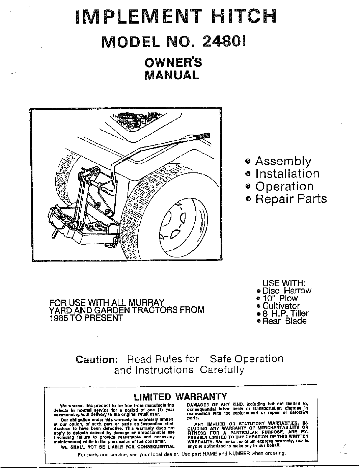
iMPLEMENT HITCH
MODEL NO. 24801
OWNER'S
MANUAL
o Assembly
® Installation
= Operation
® Repair Parts
FOR USE WITH ALL MURRAY
YARD AND GARDEN TRACTORS FROM
1985 TO PRESENT
USE WITH:
• Disc Harrow
= 10" Plow
• Cultivator
• 8 H.P. Tiller
®Rear Blade
Caution: Read Rules for Safe Operation
and Instructions Carefully
LIMITED WARRANTY
We ws_rnnl thla product to be free Item manulactur[ng
delQ(:t8 In reormll serried for Ri_(orlod of one (1} year
_,omrnen© [rig v(Jt;1dm_lvel¥ to Ihet original rBtaI[ u_ut,
Our _b[IgatJ©n under _hll warrRn_' Is aXpl_aSsly llmited_
tit our opllont of suc]l part or parta as li1_peGt[on shall
d_clcrao |o hi=re be_n dolectIve. This warreJnly doea not
a_ply _0 dofe_ cauxed by damage or unr_nBonaf01e uBe
[n©tud[ng |ldJUTe to provide reasonable and nocessar_
mB ntoTlaltCO WhlIEt in luBpOBS_lSlllun of h@C_lSum@r.
WE SHALL NOT BE LIABLE FOIl CONSEOUEHT[AL
DAMAGE_ OF ANY I(ND, .c[udTng but not nm[ted |o,
_ns_qu_n a labor ¢_SL_ or IransporhttJon charg_ Lrl
connexion with the wsplaCamenL or iopslr of deloctlve
parts,
ANY IMPLIED OR STATU/'ORY WARRANTIES, IN-
CLUDI_tG ANY WARRANTY OF MER_HAhiTABILITY OF_
FITNESS FOR A pARTICULAR [=UIFIpO$E, ARE EX*
FRESHLY LIMITED TO THE DURATION OF *l'H 18 WRITTEN
WARRANTY, V/o mBke no olher exprose ve_rranty_ not it
nrlyono _u_h_lzad to m_lke _ny in OUr behedl,
For parts and se_lce, see yeur local dealer, Use part NAME and NUM£ER when order]ng.
Page 2
A
@ Know controls and how to stop quickly, READ THE
OWNER'S MANUAL.
• 0o not allow children to operate the vehicle, do
nat allow adult_ to operate without proper
instruction and without having read the owner's
mat_uaL
@ DO not carry passengers. Keep children and pets
a safe distance away.
e Always wear $11bstantial footwear. Do not wear
loOSe fitting ctothing that can get caught in
moving parts.
® Keep yours eyes and mind on your tractor/attach*
ment and area being covered. Don't let other
interests distract you.
• Stay alert for holes in the terrain and other
hidden hazards,
RULES FOR SAFE OPERATION
• Keep the vehicle and attachments in good operating
condition and keep safety Pevices in place.
• Keep all nuts, bolts and screws tight to be sure
the equipment is in safe working condition.
Q The vehicle and attachments should be stopped and
inspected for damage after striking a foreign
object. The damage should be repalred before
restarting and operating the equipment.
• See tractor equipment owner's manual for safe
operation of the equipment.
Q Do not drive close to creeks, ditches and public
highways.
e Watch out for traffic when crossing or near
roadways.
• When using any attachments, don't allow anyone
near the vehicle while in operation.
_WARNINGI
@ Assembled Hitch has various pivoting points,
Keep Hands away when raising and towering Hitch.
• Always lower Hitch when Mounting or Removing
Attachments.
TABLE OF CONTENTS
WARRANTY ...........................................................2
SAFETY RULES ...................................................2
ASSEMBLY_,...........................................................3-_
PRE-USE HINTS ..................................................4
OPERATION .............................................................4
MAINTENANCE .......................................................4
REPAIR PARTS .......................................................5
ASSEMBLY
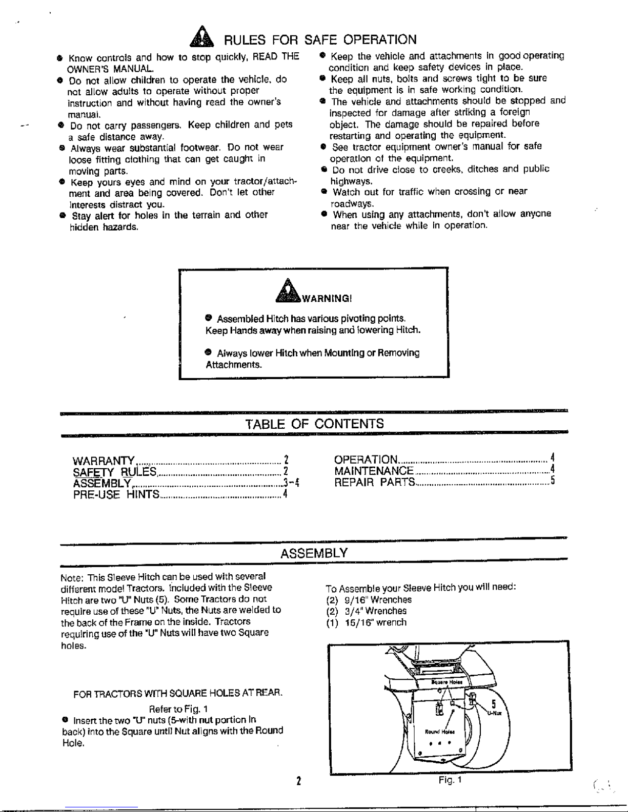
Note: This Sleeve Hitch can be used with several
different model Tractors. included with the Sleeve
Hitch are two "U" Nuts (5), Some Tractors do not
require use of these .IJ, Huts, tfte Nuts are welded to
the back of the Frame on the inside. Tractors
requiring use of the 'U" Nuts win have two Square
holes.
FOR TRACTORS WITH SQUARE HOLES AT REAR.
Refer to Fig. 1
0 Insert the two "U" nuts (5-with nut portion In
back) into the Square until Nut aligns with the Round
Hole.
To Assemble your Sleeve Hitchyouw]l! need:
(2) £/16"Wrenches
(2) 3/4"Wrencbas
(1) 15/1_'wrench
2
/
Fig. 1 / ,
Page 3

FOR ALL MOUNTINGS
Refer to Fig. 2
• Attach the Mounting Plate of the Lift Handle
Assembly (B) to back of Tractor using two 1/2" x 1-114`
Hex Bolts (6), and Lock Washers (7). Thread the Bolts
into existing "Tapped" Holes or the previously
assembled "U' Nuts,
• Seourethebottomofthe MountingPlatewBhBl8"x
1" Hex Bolts (9), Lock Washers (10), and Hex Nuts (11 ).'
I Tighten all bolts securely,
• Place Handle Grip (22) over end of Lift Hand[e
Refer to Fig g
e Attach the Hgch BaH Mounting Bracket (1) to
Tractor (resting on top of Tractor Drewbar).
• Secure with three 1/2" x 1-1 t 4" Hex Bolts (6), Flat
Washers (13}, Lock Washers (7) and Hex Nuts (B).
NOTE: Mounting Tabs must be DOWN.
• TIGHTEN SECURELY.
g Attach Short Strap (17) to Lifting Strap (B) on
Lift Handle in OUTER hole. Notch in Short Strap must
be facing down.
NOTE: When operating heavier Attachments, such as the
engine driven Tiller, position the Short Strap in the
Link Assembly into the inner hole of Lift Handle Strap.
a Securewith _/2"x f-l/2"HexBo[t(f5) andtwo
1/2" Hex Nuts (8).
NOTE: Tighten nuts snugly, but allow for free movement
of parts,
• Attach the Lgt Link Assembly (4) to tba Sbart
Strap (17).
• Secure with 318" x 1" Hex holt (9) and 3/8" Hex
Lock Nut (21). Tighten only snugly Link must ba free
to pivot.
Fig. 2
Fig,3
Refer to Fig. 4
NOTE: Determine Mounting Heles required for Hitch Bail
and Link Assembly, ("A" or "B"), Measure Diameter
(height) of rear tires;
20" Diameter (height) Tires-Use Holes "A" in Mgunting
Bracket and Link Assembly.
23" Diameter (height / Tires-Use Holes "B" in Mounting
Bracket and Link Assembly.
6 Mount the Hitch Bail (2) to the Hitch Bail Mousing
Bracket ( 1), using two 1/2" Dri]led Pins (12), two 1/2"
Plain Washers (t3), and Hairpin Cotters (14).
I Attach Link Assembly (4) to Lift Tab (C), on Hitch
Bail (2}; using, a 1/2" Drilled Pin (12), a 1/2 _ Flat
Washer (13), and a Hairpin Cotter (14).
I!l Thread 5/8" Jam Nuts (20) on two 5/8" x 2"
8t abilizer Bolts (16),
@ Thread these two bolts into welded nuts on inside
of Hitch Bail (2) until flush with outside of nuts,
• Install Stabilizer Plate [18) and Hitch Pin (19) as
showrl.
Fig 4
E:O-s-E H] I T-S
_ WARNSNG]
OAssembled Hitch has v_rious pivctin g
points, Keep hands awaywban raising
and lowering attachments,
3
@ The Mower Deck must be removed when using Sleeve
Hitch Attachments. Hitch may remain on mower when
using Mower.
Q T]re Cba[n$ and/or Wheel Weights are required for
mo_t Sleeve Hitch Attachments.
• Make sure all Bolts and Nuts ere tightened secure{y,
Page 4

OPERATION
ATFAOHING
• Attachments are mounted to Hitch using the "L" pin
furnished. Refer to yaur AKachment Manual for proper
Mounting Procedure and Operation of Attachments.
• Attachments are Raised and Lowered by making use of
the Hitch Lift Handle. Pull forward to Raise, push
Back to Lower.
• Lift Attachments out of ground when turning comers
or reversing.
22
5
\
STABILIZING
NOTE: Most Attachments require Stabll]zatlon
(elimination of "side to side" movement).
• Turn the 5/8" × 2" (16) Stabilizer Bolts Clockwise
against Stabilizer Plate (18) unSI side to side motion
is eliminated. Tighten Jam Nuts against Welded Nuts.
0 Stabilizer Bolts will have to be loosened before
Attachment can be removed.
NOTE: ]rnftortant- DO not stabilize Plow or Disc
Harrow Attachments.
SPECIAL OPERATION
NOTE: When operating heavier Attachments, such as the '
engine driven Tiller, repoedion the Link Assembly as
follows:
Refer to Fig. 3
• Attach Short 8ttap (17) to Lifting Strap on Lift
Handle in iNNER hole.
e Heavier Attachments (engine driven Tiller) will be
furnished with a Lift Assist Spring, which mounts to
the Sleeve Hitch. Refer to the Attachments Manual.
I 13 14
12
2
L
MAINTENANCE
® Apply a light coat of grease or oil to Stabilizer
Bolts and to all Pivoting Points on Hitch.
• Clean and store in a weatherproof_ dry area.
@ Touch up any scratches with enamel paint to avoid
rusting.
MODEL NUMBER 24801
PARTS LIST
REF.
NO. PART NO.
1 H-502-10
2 H-190-10
3 H-731-10
4- H-629-!0
5 H-632
6 1M1620P
7 40M130eP
8 30Mt600P
9 1M1216P
12 40M122OP
11 30M1220P
DESCRIPTION QTY.
Hitch Ball Mounting Bracket 1
Hitch Bail 1
Lift Handle Assembly 1
Lift Link 1
"U" Nut 2
HexBolt, 1/2" x1-1/4" 5
Lock Washer, 1/2" 5
HexNut, 1/2" 5
Hex Bolt, 2/8' x 1" 3
Lock Washer, 8/8" 2
He× Nut, 8/2" 2
REF.
NO. PART NO. DESCRIPTION
12 V-319P Dril[ed Pin
13 4BM1717P Flat Washer, 1/2"
14 D-146P Hairpin Cotter
15 1M1624P HexBolt, 1/2"x 1-1/2"
16 H-293P He×Boit, 5/8"x2"
17 H 510-10 Short Strap
18 H-158_10 Stabilizer Plat e
19 H-132P-Ol Hitch Pin
20 81M2000P Jam Nut, 5/8'
21 B-1575P Hex Lock Nut, 3/8"
22 B4_72 HandEe Grip
QTY.
2
7
8
1
2
1
1
I
2
1
I
L-1571 , PRINTEDINUS,A.
 Loading...