

Page 1
1738207
en
Not for
Reproduction
Operator’s Manual
de
fi
it
no
sv
Bedienungsanleitung
Käyttäjän käsikirja
Manuale dell’Operatore
Brukerhåndbok
Instruktionsbok
Walkbehind Snowthrower
Mfg. No. Description
1695691 Dual Stage Snowthrower, 11.50 TP, 27 Inch (68,6 cm)
1
Revision E
09/2009
Page 2

Not for
Reproduction
2
Page 3
1
Not for
Reproduction
See Page 15.
5
2
3
A B
B
A
B
C
6
C
B
4
E
A
D
C
A
3
Page 4
7
Not for
Reproduction
10 11
12
See Pages 18 and 19.
A D
C
A
8
A
D
C
B
13
D
A
B
B
9
B
A
4
Page 5
14
FULL
Not for
Reproduction
18
A
C
B
A
15
16
19
A
B
A
A
20
A
B
17
21
B
A
A
5
Page 6
22
E
D
Not for
Reproduction
26
A
Full
A
23
24
27
B
B
C
A
28
C
B
C
A
B
A
C
6
25
A
B
C
A
B
29
A
B C
Page 7
1/2” (12.5mm)
Deflection
8
3
.030 in.
(.76 mm)
30
1/32”
(0.8mm)
Screw
B
C
Not for
Reproduction
34
31
A B
1/8” (3mm)
C
35
A
B
A
32
33
B
A
A
36
37
D
E
A
B
C
F
B
A
7
Page 8
38
“A”
A
B
C
Not for
Reproduction
41
A
C
D
B
39
40
42
A
A
8
Page 9
CONTENTS
Not for
Reproduction
Illustrations ...........................................................................................3
Operator Safety......................................................................................10
Assembly.............................................................................................16
Features and Controls..............................................................................17
Operation.............................................................................................19
Maintenance.........................................................................................23
Storage ...............................................................................................28
Troubleshooting .....................................................................................29
Warranty .............................................................................................31
Specifications .......................................................................................32
General Information
Thank you for purchasing this quality-built Murray snowthrower. We’re pleased that you’ve placed your confidence in the Murray brand.
When operated and maintained according to the instructions in this manual, your Murray product will provide many years of
dependable service.
This manual contains safety information to make you aware of the hazards and risks associated with snowthrowers and how to avoid
them. This snowthrower is designed and intended only for snow throwing and is not intended for any other purpose. It is important that
you read and understand these instructions throughly before attempting to start or operate this equipment. This snowthrower requires
final assembly before use. Refer to the Assembly section for instructions on final assembly procedures. Follow the instructions
completely. Save these instructions for future reference.
Product Reference Data
Record your model name/number, manufacturer’s identification
numbers, and engine serial numbers in the space provided for
easy access. These numbers can be found in the locations
shown.
When contacting your authorized dealer for replacement
parts, service, or information you MUST have these numbers.
PRODUCT REFERENCE DATA
Model Description Name/Number
Unit MFG Number Unit SERIAL Number
Mower Deck MFG Number Mower Deck SERIAL Number
Dealer Name Date Purchased
ENGINE REFERENCE DATA
Engine Make Engine Model
Engine Type/Spec Engine Code/Serial Number
CE Identification Tag
A. Manufacturer’s Identification Number
B. Manufacturer’s Serial Number
C. Power Rating in Kilowatts
D. Maximum Engine Speed in Rotations per Minute
E. Manufacturer’s Name and Address
F. Year of Manufacture
G. CE Compliance Logo
H. Mass of Unit in Kilograms
I. Guaranteed Sound Power in Decibels
A
Part No. xxxxxxx
B
E
xxxxxxxxxxxxxxx
Serial No. xxxxxxxxxx
xxxxxxxxxxxxxxxxxxxxxxx
xxxxxxxxxxxxxxxxxxxxxxx
xxxxxxxxxxxxxxxxxxxxxxx
xxxxxxxxxxxxxxxxxxxxxxx
xxx dB
20xx
F
kg: xxx
kW: x.xx
xxxx max
G
I
H
C
D
The Illustrated Parts List for this machine can be downloaded from www.simplicitymfg.com. Please provide model and serial number
when ordering replacement parts.
Copyright © 2009 Briggs & Stratton Power Products Group, LLC
Milwaukee, WI, All rights reserved.
SIMPLICITY is a trademark of Briggs & Stratton Power Products
Group, LLC Milwaukee, WI USA.
9
Page 10

OPERATOR SAFETY
Not for
Reproduction
DANGER - Amputation Hazard
The discharge chute contains a rotating
impeller to throw snow. Never clear or unclog
the discharge chute with your hands. Fingers
can quickly become caught and traumatic
amputation or severe laceration will result.
Always use a clean-out tool to clear or unclog
the discharge chute.
DANGER
• Hand contact with the rotating impeller inside the discharge
chute is the most common cause of injury associated with
snow throwers.
• This snow thrower is capable of amputating hands and feet,
and throwing objects. Read and observe all the safety
instructions in this manual. Failure to do so will result in
death or serious injury.
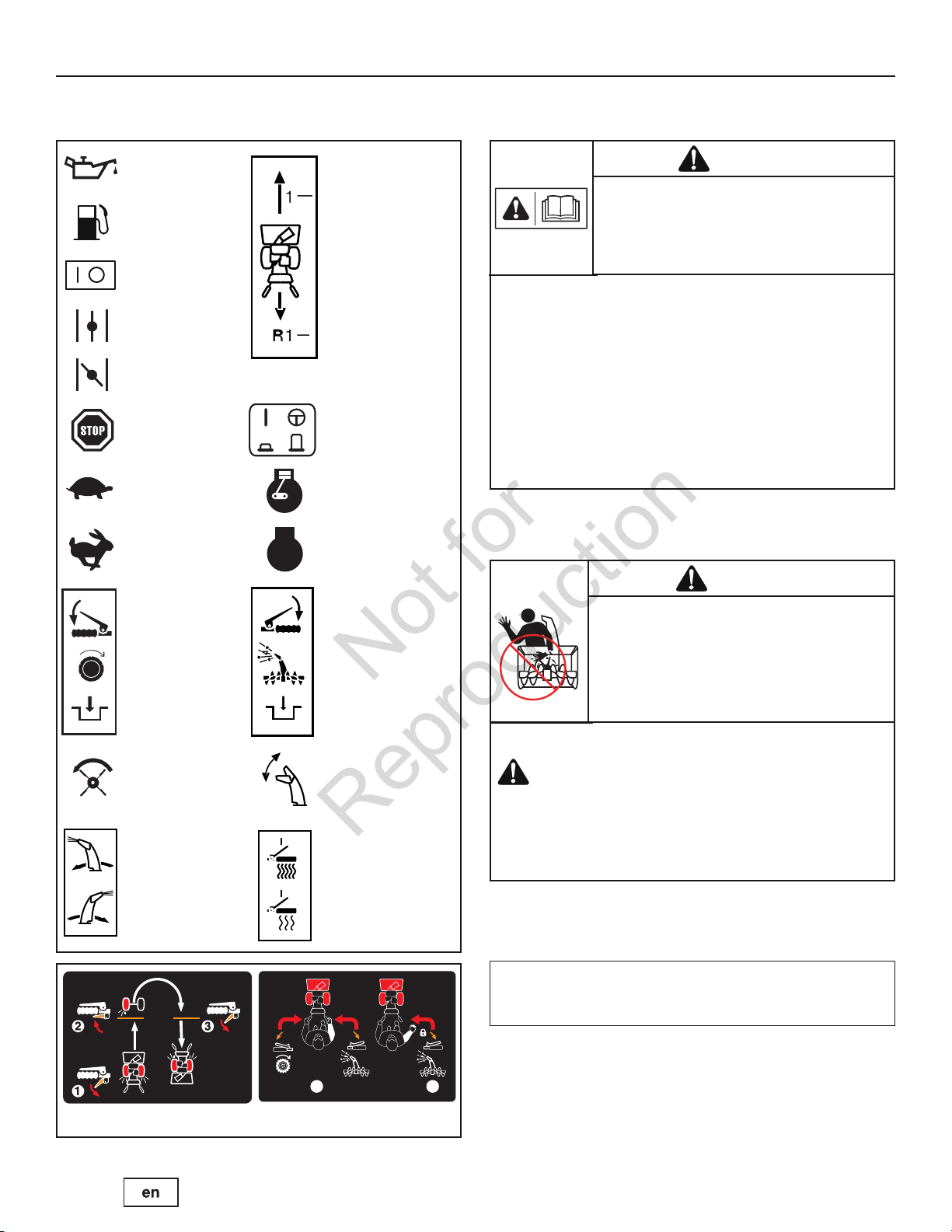
Safety Alert Symbol and Signal Words
The safety alert symbol and signal word (DANGER,
WARNING, CAUTION, or NOTICE) is used to indicate the
likelihood and potential severity of personal injury and/or damage
to the product. In addition, a hazard symbol may be used to
represent the type of hazard.
Hazard Symbols and Meanings
Safety Alert – Identifies safety information about
hazards that can result in personal injury.
Operator’s Manual – Read and understand before
performing any activity or running snow thrower.
Rotating Impeller
Rotating Auger Rotating Gears
Never Reach into
Rotating Parts
Fire Explosion
Shock Toxic Fumes
Keep a Safe
Distance from
Snow Thrower
Thrown Objects
DANGER indicates a hazard which, if not avoided, will
result in death or serious injury.
WARNING indicates a hazard which, if not avoided, could
result in death or serious injury.
CAUTION indicates a hazard which, if not avoided, could
result in minor or moderate injury.
NOTICE indicates a situation that could result in damage
to the product.
WARNING
U.S.A. Models: Certain components in this product and its
related accessories contain chemicals known to the state of
California to cause cancer, birth defects, or other
reproductive harm. Wash hands after handling.
Recommended Ear
Hot Surface
Shut off engine and remove spark plug connector
before performing maintenance or repair work.
Protection for
Extended Use
WARNING
U.S.A. Models: The engine exhaust from this product contains
chemicals known to the State of California to cause cancer,
birth defects, or other reproductive harm.
10 www.murray.com
Page 11
1
2
Free-HandTMControlEasy-TurnTMTraction Control
Read, understand, and follow all the instructions on the
snow thrower and in the operator’s manual before operating
this unit.
Failure to observe the safet y instructions in this manual
will result in death or serious injury.
DANGER: Hand contact with the rotating impeller inside the discharge
chute is the most common cause of injury associated with snow
throwers. Never use your hands to clean out the discharge chute.
Discharge chute contains rotating impeller to throw snow.
Never clear or unclog the discharge chute with your hands.
Fingers can quickly become caught in the impeller. Always
use a clean-out tool.
Failure to observe these safety instructions will result in
traumatic amputation or severe laceration.
OPERATOR SAFETY
Not for
Reproduction
Control Symbols on Equipment
Oil
Fuel Forward
On Off Neutral
Choke Off Reverse
Choke On
Stop
Slow Engine - Run
Fast
STOP
Electric Start Engage (Down) &
Disengage (Up)
Engine - Stop
Read the Manual
DANGER
• Be thoroughly familiar with the controls and the proper use of the snow
thrower.
• Make sure you are properly trained before operating the snow thrower.
• Know how to stop the unit and disengage the controls quickly.
• Never allow anyone to operate the snow thrower without proper instruction.
• Always follow the instructions in the operator’s manual, if the snow thrower
will be stored for an extende d period.
• Maintain or replace safety and instruction labels as necessary.
• Never attempt to make major repairs on the snow thrower unless you have
been properly trained. Improper servicing of the snow thrower can result in
hazardous operation, equipment damage, and voiding of the product
warranty.
Discharge Chute
Traction Control Engage (Down)
Auger Clutch
Discharge Chute
(Left and Right)
Auger Control Engage (Down)
Chute Deflector
(Up and Down)
Heated Hand Grips
(High and Low)
DANGER
TO SAFELY CLEAR A CLOGGED DISCHARGE CHUTE
FOLLOW THESE INSTRUCTIONS:
1. Shut OFF the engine.
2. Wait 10 seconds to be sure the impeller blades have stopped rotating.
3. Always use a clean-out tool, not your hands.
NOTE: Not all control symbols shown on this page will appear
on your snow thrower. See FEATURES AND CONTROLS section
for the applicable symbols.
11
Page 12
Fuel and its vapors are extremely flammable and explosive.
Always handle fuel with extreme care.
Failure to observe these safety instructions can cause a fire
or explosion which will result in severe burns or death.
This snow thrower is only as safe as the operator. If it is
misused, or not properly maintained, it can be dangerous.
Remember you are responsible for your safety and that of
those around you.
OPERATOR SAFETY
Not for
Reproduction
Operation and Equipment Safety
DANGER
• Keep the area of operation clear of all persons, particularly small children
and pets.
• Thoroughly inspect the area where the snow thrower will be used and remove
all doormats, sleds, boards, wires, and other foreign objects.
• Do not operate the snow thrower without wearing adequate winter clothing.
• Wear footwear that will improve footing on slippery surfaces.
• Use caution to avoid slipping or falling especially when operating the snow
thrower in reverse.
• Never operate the snow thrower without good visibility or light. Always be
sure of your footing, and keep a firm hold on the handles.
• Do not clear snow across the face of slopes. Use extreme caution when
changing direction on slopes. Do not attempt to clear steep slopes.
• Do not overload the machine capacity by attempting to clear snow too
quickly.
• Never operate the snow thrower at high transport speeds on slippery
surfaces. Look behind the snow thrower and use care when operating in
reverse.
• Do not use the snow thrower on surfaces above ground level such as roofs of
residences, garages, porches, or other such structures or buildings.
• Operators should evaluate their ability to operate the snow thrower safely
enough to protect themselves and others from injury.
• The snow thrower is intended to remove snow only. Do not use the snow
thrower for any other purpose.
• Do not carry passengers.
• After striking a foreign object, shut OFF the engine, disconnect the cord on
electric motors, thoroughly inspect the snow thrower for any damage, and
repair the damage before restarting and operating the snow thrower.
• If the snow thrower vibrates abnormally, shut OFF the engine. Vibration is
generally a warning of trouble. See an authorized dealer if necessary for
repairs.
• For models equipped with electric starting motors, disconnect the power cord
after the engine starts.
Fuel Handling
DANGER
WHEN ADDING FUEL
• Turn off engine and let cool at least 2 minutes before removing the fuel cap
and adding fuel.
• Fill fuel tank outdoors or in a well ventilated area.
• Do not overfill the fuel tank. To allow for the expansion of gasoline, do not fill
above the bottom of the fuel tank neck.
• Keep fuel away from sparks, open flames, pilot lights, heat, and other ignition
sources.
• Check fuel lines, cap, and fittings frequently for cracks or leaks. Replace if
necessary.
• Use an approved fuel container.
• If fuel spills, wait until it evaporates before starting engine.
WHEN STARTING ENGINE
• Ensure that spark plug, muffler, fuel cap, and air cleaner (if equipped) are in
place and secured.
• Do not crank the engine with the spark plug removed.
• If fuel is spilled, do not attempt to start the engine, but move the snow
thrower away from the area of the spill, and avoid creating any source of
ignition, until the fuel vapors have dissipated.
• Do not over-prime the engine. Follow the engine starting instructions in this
manual.
• If the engine floods, set choke (if equipped) to OPEN/RUN position, move
throttle (if equipped) to FAST position and crank until engine starts.
WHEN OPERATING EQUIPMENT
• Do not tip the snow thrower at an angle which causes the fuel to spill.
• Do not choke the carburetor to stop the engine.
• Never run the engine with the air cleaner assembly (if equipped) or the air
filter (if equipped) removed.
WHEN CHANGING OIL
• If you drain the oil from the top oil fill tube, the fuel tank must be empty or
fuel can leak out and result in a fire or explosion.
WHEN TRANSPORTING EQUIPMENT
• Transport with fuel tank EMPTY, or with fuel shut-off valve OFF.
WHEN STORING GASOLINE OR EQUIPMENT WITH FUEL IN TANK
• Store away from furnaces, stoves, water heaters, or other appliances that
have pilot light or other ignition source because they can ignite fuel vapors.
12 www.murray.com
Page 13
Tragic accidents can occur if the operator is not alert to the
presence of children. Children are often attracted to the unit
and the operating activity. Never assume that children will
remain where you last saw them.
Engines give off carbon monoxide, an odorless, colorless,
poison gas.
Breathing carbon monoxide can cause nausea, fainting, or
death.
Safe operation of the snow thrower requires the proper care
and maintenance of the engine. Failure to observe the safety
instructions in this manual will result in death or serious
injury.
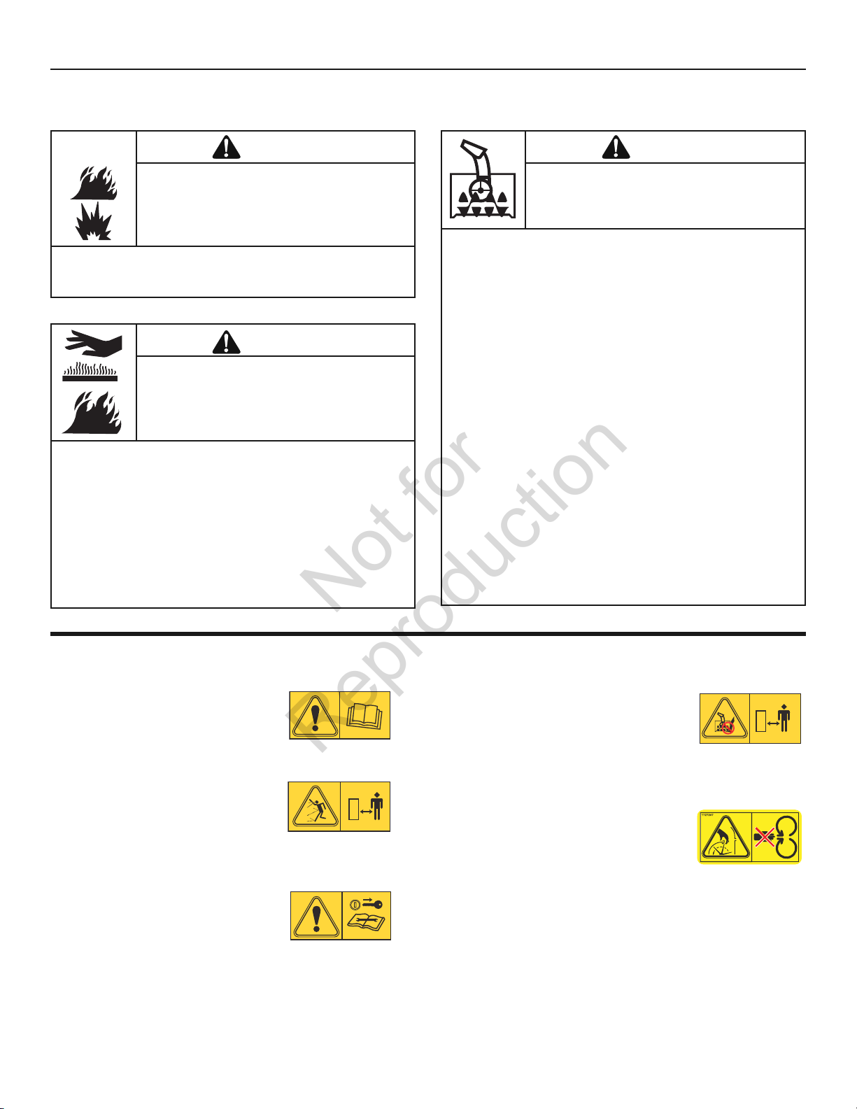
Objects can be picked up by auger and thrown from chute.
Never discharge snow toward bystanders or allow anyone in
front of the snow thrower. Failure to observe these safety
instructions will result in death or serious injury.
Keep hands, feet, and clothing away from rotating parts.
Rotating parts can contact or entangle hands, feet, hair,
clothing, or accessories.
Failure to observe these safety instructions will result in
traumatic amputation or severe laceration.
OPERATOR SAFETY
Not for
Reproduction
Moving Parts
DANGER
• Whenever cleaning, repairing, or inspecting the snow thrower, make sure the
engine is OFF, spark plug wire is disconnected, and all moving parts have
stopped.
• Do not put hands or feet near or under rotating parts. Keep clear of the
discharge opening at all times.
• Never operate the snow thrower without proper guards, and other safety
devices in place and working.
• Never leave the snow thrower unattended while engine is running. Always
disengage the auger and traction controls, stop engine, and remove keys.
• Keep all loose clothing away from the front of the snow thrower and auger.
Scarves, mittens, dangling drawstrings, loose clothes, and pants can quickly
become caught in the rotating device and amputation will occur. Tie up long
hair and remove jewelry.
• Run the machine a few minutes after discharging snow to prevent freeze-up
of the collector/impeller.
• Disengage power to the collector/impeller when snow thrower is transported
or not in use.
Thrown Objects
Children
DANGER
• Keep children out of the area during operation. Children are often attracted to
the equipment. Be mindful of all persons present.
• Be alert and turn unit off if children enter the area.
• Never allow children to operate the unit.
• Use extra care when approaching blind corners, shrubs, trees, or other
objects that may obscure vision. Children may be present.
Engine Safety
DANGER
• Disengage all clutches and shift into neutral before starting the engine.
• Let the engine adjust to outdoor temperatures before starting to clear snow.
• Use a grounded three-wire plug-in for all snow throwers equipped with
electric drive motors or electric starting motors.
DANGER
• Always wear safety glasses or eye shields while during operation, and while
performing an adjustment or repair.
• Always be aware of the direction the snow is being thrown. Nearby
pedestrians, pets, or property may be harmed by objects being thrown.
• Be aware of your environment while operating the snow thrower. Running
over items such as, gravel, doormats, newspapers, toys, and rocks hidden
under snow, can all be thrown from the chute or jam in the auger.
• Use extreme caution when operating on or crossing gravel drives, walks, or
roads.
• Adjust the collector housing height to clear gravel or crushed rock surface.
• Never operate the snow thrower near glass enclosures, automobiles, window
wells, drop-offs, and the like without proper adjustment of the discharge
chute angle.
• Familiarize yourself with the area in which you plan to operate the
snowthrower. Mark off boundaries of walkways and driveways.
DANGER
• Start and run engine outdoors.
• Do not run the engine in an enclosed area, even if doors or windows are
open.
13
Page 14
This snow thrower must be properly maintained to ensure
safe operation and performance. Failure to observe the safety
instructions in this manual could result in death or serious
injury.
Starting engine creates sparking.
Sparking can ignite nearby flammable gases.
Explosion and fire could result.
U.S.A. Models:
Running the engine produces heat. Engine parts, especially
muffler, become extremely hot.
Failure to observe these safety instructions could result in
severe thermal burns on contact.
OPERATOR SAFETY
Not for
Reproduction
Engine Safety (Continued)
WARNING
-
• If there is natural or LP gas leakage in area, do not start engine.
• Do not use pressurized starting fluids because vapors are flammable.
WARNING
• Never touch a hot engine or muffler. Allow muffler, engine cylinder, and fins
to cool before touching.
• Remove debris from muffler area and cylinder area.
• Install and maintain in working order a spark arrester before using equipment
on forest-covered, grass-covered, or brush-covered unimproved land.
•U
4442 to use or operate the engine on or near any forest-covered, brushcovered, or grass-covered land unless the exhaust system is equipped with a
spark arrester meeting any applicable local or state laws. Other states or
federal areas may have similar laws.
It is a violation of California Public Resource Code Section
Maintenance and Storage
WARNING
• When performing any maintenance or repairs on the snow thrower, shut OFF
the engine, disconnect spark plug wire, and keep the wire away from the plug
to prevent someone from accidently starting the engine.
• Check shear bolts and other hardware at frequent intervals for proper
tightness to be sure the snow thrower is in safe working condition.
• Keep nuts and bolts tight and keep snow thrower in good condition.
• Never tamper with safety devices. Check their proper operation regularly and
make necessary repairs if they are not functioning properly.
• Components are subject to wear, damage, and deterioration. Frequently
check components and replace with recommended parts, when necessary.
• Check control operation frequently. Adjust and service as required.
• Use only factory authorized replacement parts when making repairs.
• Always comply with factory specifications on all settings and adjustments.
• Only authorized service locations should be utilized for major service and
repair requirements.
• Use only attachments and accessories approved by the factory (such as
wheel weights, counterweights, or cabs).
• Never attempt to make any adjustments while the engine is running (except
when specifically recommended by the factory).
• Do not allow grease or oil to contact the rubber friction wheel or the disc
drive plate. If the disc drive plate or friction wheel come in contact with
grease or oil damage to rubber friction wheel will result.
SAFETY ICONS
DANGER: READ OPERATOR’S
MANUAL.
Read the Operator’s Manual for
operating and safety instructions.
DANGER: THROWN OBJECTS
HAZARD.
Never direct discharge chute
towards persons or property. Keep
bystanders away.
DANGER: REMOVE KEY BEFORE
SERVICING.
Shut off engine and remove key
before performing maintenance or
repair work.
DANGER: AMPUTATION HAZARD.
Contact with auger will cause
serious injury. Keep hands, feet, and
clothing away. Keep bystanders
away.
DANGER: AMPUTATION HAZARD.
Contact with moving parts inside
chute will cause serious injury. Shut
off engine before unclogging
discharge chute. Use clean-out tool,
not hands!
14 www.murray.com
Page 15
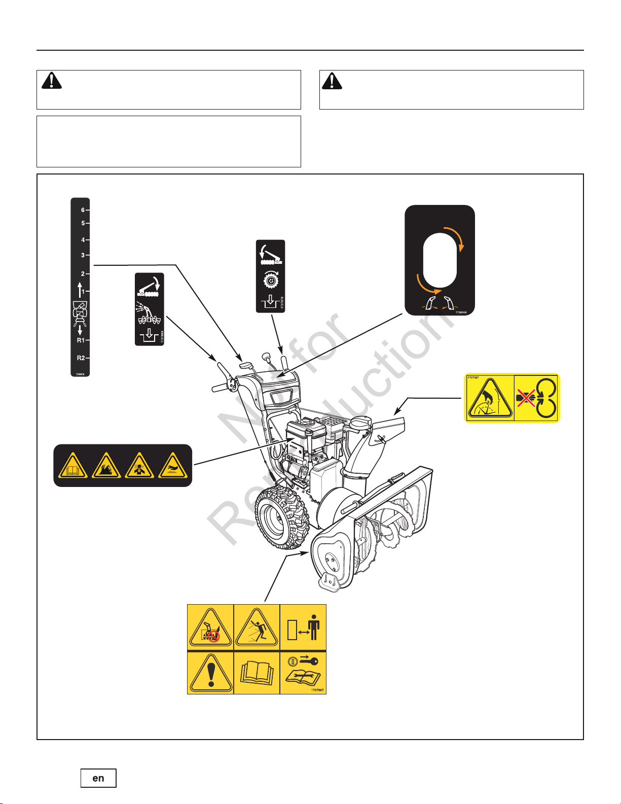
OPERATOR SAFETY
Not for
Reproduction
Look for this symbol to indicate important safety
precautions. This symbol indicates: “Attention!
Become Alert! Your Safety Is At Risk.”
Before operating your snow thrower, read the safety decals as
shown on your snow thrower. The cautions and warnings are
for your safety. To avoid a personal injury or damage to your
snow thrower, understand and follow all the safety decals.
Part No. 1736616
Shift Decal
Part No. 1737869
Auger Control Decal
Part No. 1737870
Traction Control Decal
WARNING: If any safety decals become worn or
damaged and cannot be read, order replacement decals
from your local dealer.
Part No. 1738348
Main Dash Decal
Engine Warning Icons
Part No. 276925
Product ID Number &
Serial Number Decal
(Rear of Motor Box)
Part No. 1737867
Auger Control Icons
Part No. 1727207
Chute Control Icons
Safety Decals Figure 1
15
Page 16
ASSEMBLY
B
B
B
Not for
Reproduction
TOOLS REQUIRED FOR ASSEMBLY
1 – Knife
2 – 1/2" Wrenches (or adjustable wrenches)
1 – 7/16” Wrenches (or adjustable wrenches)
1 – Wrench (or adjustable wrench)
1 – Pair pliers or screw driver (to spread cotter pin)
1 – Hammer
1 – Pry Bar
PARTS BAG CONTENTS
1 – Shear Bolt Kit, 1/4-20 x 1-3/4 in.
1 – Bag of Shear Bolts
1 – Screw, 1/4-20 x 1-3/4 in.
1 – Spacer, Sleeve, 1/4 in.
1 – Hex Locknut, 1/4-20
1 – Fresh Fuel Packet
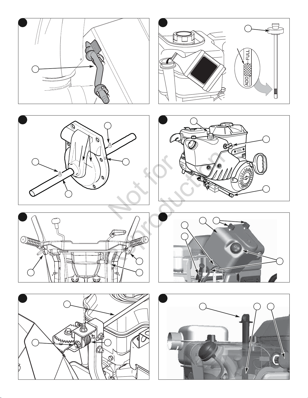
NOTE: “Right” and “Left” are from the Operating Position.
WARNING: Always wear safety glasses or eye shields
when assembling the snow thrower.
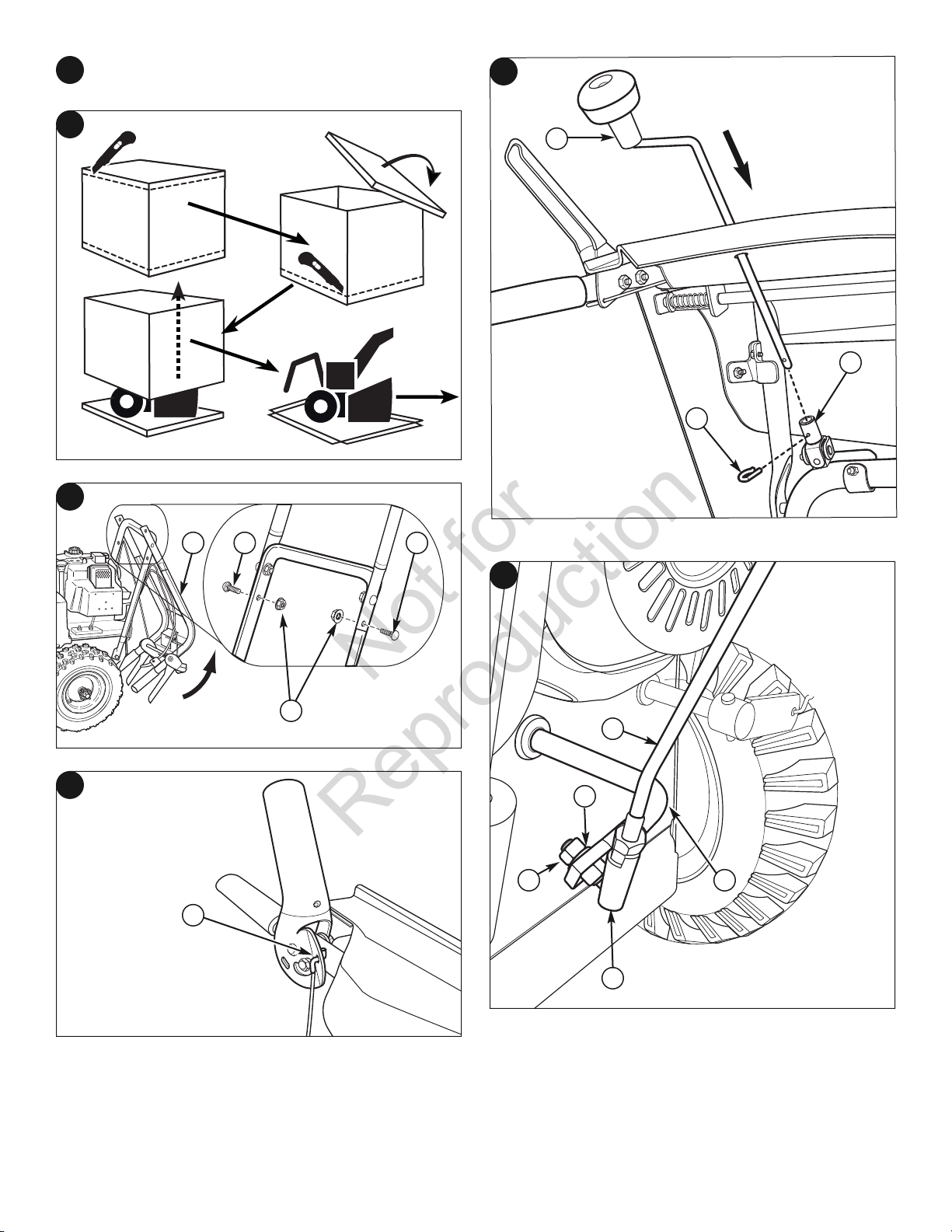
UNPACK THE SNOW THROWER
1. Using knife, cut along the dotted lines around the top of the carton.
Then remove top of carton as shown in Figure 2.
2. Using knife, cut along the dotted lines around the bottom of the
carton.
3. Push snow thrower off the bottom of the carton to proceed with
assembly.
ASSEMBLE THE HANDLES
1. Raise the upper handle (AA, Figure 3) to the operating position.
2. Guide speed control rod over wheel.
3. Remove blue shipping tape from cables and cut orange zip ties that
secure control cables to handle assembly and chute rotation parts.
INSTALL THE SPEED CONTROL ROD
Attach the ball joint (AA, Figure 6), located on the bottom end of the speed
control rod (B
and 5/16" nut (EE).
), to the shift yoke assembly (CC) with 5/16" lock washer (DD)
CHECK CABLE CONNECTION AND ADJUSTMENT
The traction control cable (AA, Figure 7) and auger control cable (BB) are
adjusted at the factory and no adjustment should be necessary.
If the cables become stretched, unattached or begin to sag, adjustment
will be necessary. See MAINTENANCE section of this manual.
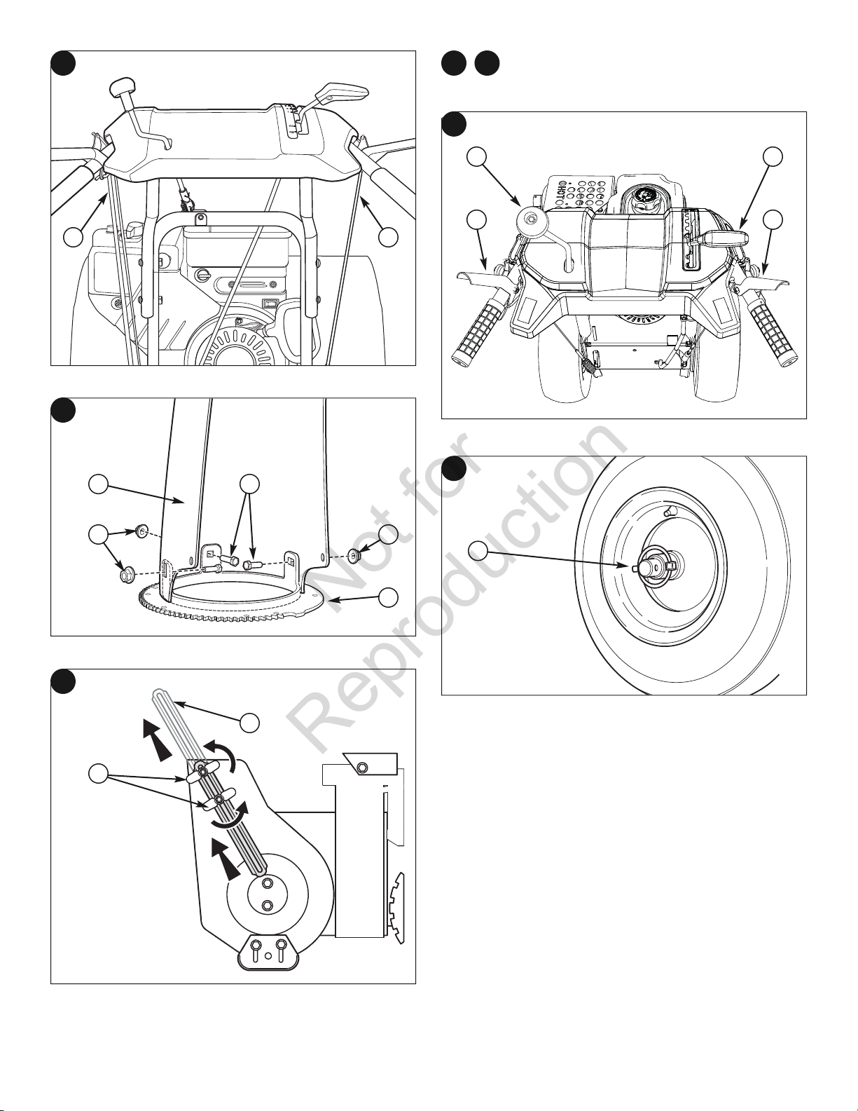
INSTALL THE DISCHARGE CHUTE
1. Place discharge chute (AA, Figure 8) over tabs on chute ring (BB) as
shown.
2. Secure discharge chute with three carriage bolts (CC) and nuts (DD).
3. Tighten hardware to 66 in-lbs (7.6 Nm).
NOTE: Check all bolts and nuts in flange for tightness. Do not
over-tighten.
NOTE: If the chute rotation is slow or binding, loosen the
chute rotation screw 1/4 turn.
INSTALL THE DRIFT CUTTER
Drift cutters are used to cut a path through snow deeper than the auger
housing.
1. Loosen the wing nuts (AA, Figure 9) that secures the drift cutters (BB) to
the auger housing.
2. Raise the drift cutters to the desired height.
3. Tighten the wing nuts.
CHECK THE TIRES
Check tires for damage. Check the air pressure in the tires with an
accurate gauge. See the sidewall of the tire for the proper inflation.
NOTE: Make sure the “Z bend ends of the control lever cables
are secured in the holes on the control levers (A, Figure 4).
Be careful not to cut or damage the control cables. Make sure
the cables are not caught between the upper and lower
handle.
4. Slide two carriage bolts (B
two 5/16" lock nuts (CC). Tighten all four carriage bolts and nuts with a
1/2" wrench or deep socket.
, Figure 3) into lower holes and fasten with
INSTALL THE CHUTE ROTATION CRANK
1. Insert chute rotator crank rod (AA, Figure 5) through hole in dash and
subdash.
2. Align small holes before inserting end of rod into universal bushing
(B
3. Push straight side of hair pin (CC) through both small holes until it
clicks into place.
16 www.murray.com
).
CAUTION: Avoid Injury! Explosive separation of tire
and rim parts is possible when they are serviced
incorrectly.
• Do not attempt to mount a tire without the proper
equipment and experience to perform the job.
• Do not inflate the tires above the recommended
pressure.
• Do not weld or heat a wheel and tire assembly. Heat can
cause an increase in air pressure resulting in an
explosion. Welding can structurally weaken or deform
the wheel.
• Do not stand in front or over the tire assembly when
inflating. Use appropriate tool that allows you to stand
to one side.
NOTICE: Check side of tire for maximum tire pressure. DO
NOT exceed maximum.
Page 17
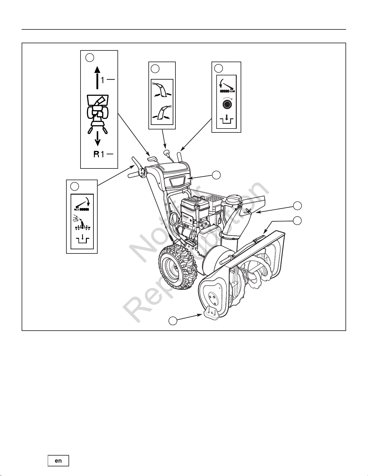
FEATURES AND CONTROLS
B
A
C
E
F
G
D
H
Not for
Reproduction
Snow Thrower Controls Figure 10
SNOW THROWER AND ENGINE CONTROLS
SNOW THROWER CONTROLS
A. Speed Select Lever — Allows the operator to use one of six (6)
forward and two (2) reverse speeds (see Figure 10). To shift, move
speed select lever to desired position.
NOTICE: Do not move speed select lever while Traction
Drive Clutch is engaged. This may result in severe damage
to drive system.
B. Auger Control Lever — Used to engage and disengage the auger
and impeller. To engage push down, to disengage release.
C. Chute Rotation Crank — Used to rotate the discharge chute to the
left or right.
D. Chute Deflector Wing Nut — Used to control the angle of the
chute deflector (up or down).
E. Traction Control Lever — Used to propel snow thrower forward or
reverse. Push down to engage, release to disengage.
F. Skid Shoe — Used to adjust ground clearance of auger housing.
G. Clean-Out Tool — Used to remove snow and debris from the
discharge chute and the auger housing.
H. Headlight — Used to operate the snow thrower in poor lighting
conditions.
17
Page 18
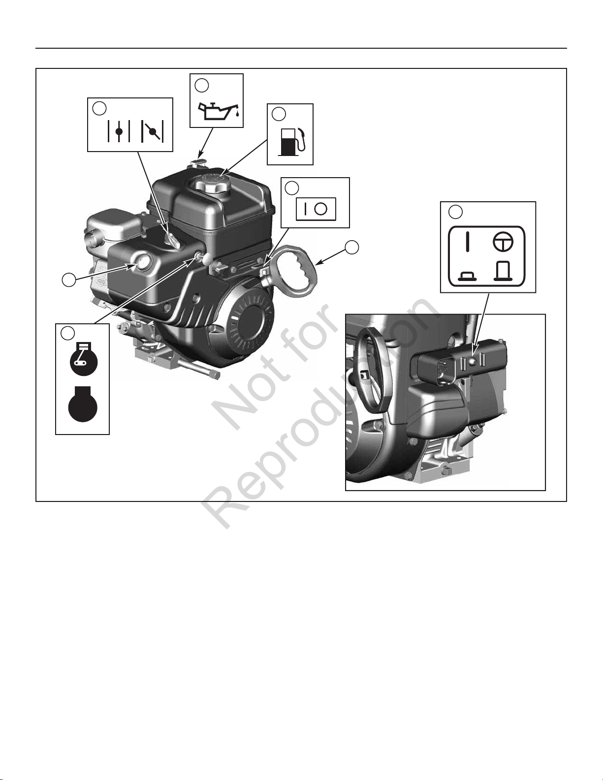
FEATURES AND CONTROLS
C
H
A
F
E
B
G
D
Not for
Reproduction
STOP
Engine Controls Figure 11
ENGINE CONTROLS
A. Choke Control Knob — Used to start a cold engine (see
Figure 11).
B. Electric Start Button — Used to start the engine using the electric
starter.
C. Primer Button — Used to inject fuel directly into the carburetor
manifold to ensure fast starts in cool weather.
D. Safety Key — Must be inserted to start engine. Pull out to stop. Do
not turn safety key.
E. Starter Cord Handle — Used to start the engine manually.
F. ON/OFF Switch — Used to start and stop the engine.
G. Fuel Tank and Cap — Fill the fuel tank to approximately 1-1/2 in.
(38 mm) below the top of the neck to allow for fuel expansion.
H. Oil Fill Cap (Extended Dipstick)
18 www.murray.com
Page 19
A
OPERATION
■
■
C
B,
A
A
Not for
Reproduction
BEFORE OPERATING SNOW THROWER
Check the fasteners. Make sure all fasteners are tight.
Read this OPERATOR’S MANUAL and OPERATOR SAFETY before
operating your snow thrower. Compare the illustrations with
your SNOW THROWER to familiarize yourself with the location of
various controls and adjustments. Save this manual for future
reference.
WARNING: The operation of any snow thrower can result in foreign objects being thrown into the eyes, which can result
in severe eye damage. Always wear safety glasses or eye shields before beginning snow thrower operation. We
recommend standard safety glasses or Wide Vision Safety Mask over spectacles.
OPERATE THE SNOW THROWER
CAUTION: Operation with a Snow Cab. Wind may blow
exhaust gasses back towards the operator. If you notice
the smell of exhaust, change direction of operation.
NOTICE: Do not throw snow toward a building as hidden
objects could be thrown with sufficient force to cause damage.
1. Start the engine. See “Start the Engine” in this section.
2. Turn the chute rotation crank (A
right) of the discharge chute. See “Discharge Chute and Deflector” in
this section.
3. Loosen the wing nut (A
to set angle (up or down) the snow is thrown. See “Discharge Chute
and Deflector” in this section.
, Figure 12) to set the direction (left or
, Figure 15) on the side of the discharge chute
NOTE: This snow thrower was shipped WITH OIL in the engine.
See “Before Starting Engine” instructions in the OPERATION
section of this manual before starting engine.
6. Use the speed select lever (DD) to select the forward drive speed. Set
the speed select lever to one of the following positions as determined
by snow conditions:
1-2 Wet, Heavy, Slushy, Extra Deep
3 Moderate
4-5 Very Light
6 Transport
NOTE: When clearing wet, heavy, snow, it is recommended
that the ground speed of the unit be reduced, maintained full
throttle and do not attempt to clear the full width of the unit.
7. To stop moving forward, release the traction control lever (C
8. To move the snow thrower backwards, move the speed select lever
into either first or second reverse position and engage the traction
control lever.
).
CAUTION: Before operating, make sure the area in
front of the snow thrower is clear of bystanders or
obstacles.
4. Fully press and hold the auger control lever (B
the auger rotation. Releasing the auger control lever will disengage
the auger.
5. Fully press and hold the traction control lever (CC) to engage the
traction drive and begin moving the snow thrower. To disengage the
traction drive, completely release the lever.
NOTE: Always release the traction control lever before moving
the speed select lever.
Figure 12) to engage
STOP THE SNOW THROWER
1. Release the auger control lever (BB,Figure 12).
2. Release the traction control lever (CC).
3. Push the ON/OFF switch (A
out the safety key (BB).
WARNING: Never run engine indoors or in an enclosed,
poor ventilated area. Engine exhaust contains CARBON
MONOXIDE, an ODORLESS and DEADLY GAS.
• Keep hands, feet, hair, and loose clothing away
from any moving parts on engine and snow
thrower.
• Temperature of muffler and nearby areas can
exceed 150°F (66°C). Avoid these areas.
• DO NOT allow children or young teenagers to
operate or be near snow thrower while it is
operating.
, Figure 21) to the OFF position and pull
19
Page 20
OPERATION
Not for
Reproduction
WARNING: Read Operator’s Manual before operating
machine. This machine can be dangerous if used
carelessly.
• Never operate the snow thrower without all
guards, covers, shields in place.
• Never direct discharge towards windows or allow
bystanders near machine while engine is
running.
• Stop the engine whenever leaving the operating
position.
• Disconnect spark plug before unclogging the
impeller housing or the discharge chute and
before making repairs or adjustments.
• When leaving the machine, remove the safety key.
To reduce the risk of fire, keep the machine clean
and free from spilled gas, oil, and debris.
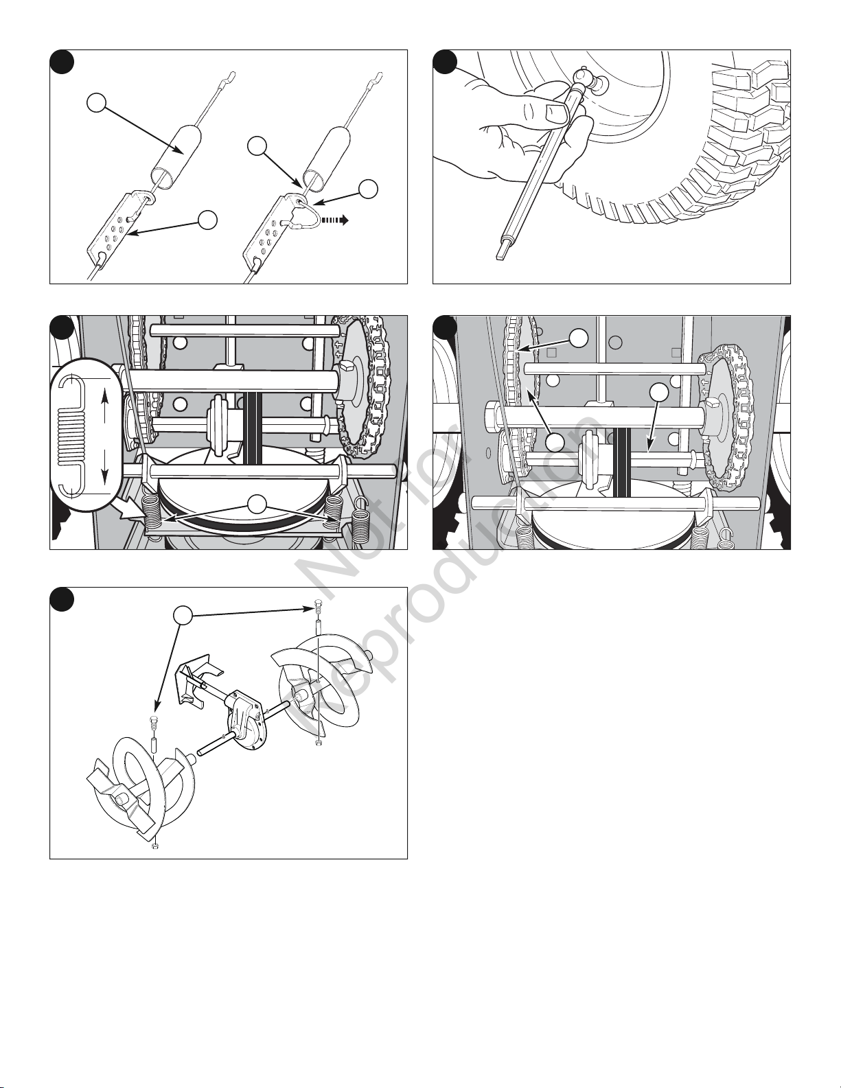
TRACTION LOCK PINS
The right traction wheel can be completely released using the locking pin
(AA, Figure 13). This allows the unit to be easily moved with the engine off.
DISCHARGE CHUTE AND DEFLECTOR
CHECK THE OIL (BEFORE STARTING ENGINE)
NOTE: The engine was shipped from the factory filled with oil.
Check the level of the oil. Add oil as needed.
1. Make sure the unit is level. Use a high quality detergent oil classified
“For Service SF, SH, SJ, SL, or higher”.
2. Remove the oil fill cap/dipstick (AA, Figure 16) and wipe with a clean cloth.
3. Insert the oil fill cap/dipstick and turn clockwise to tighten.
4. Remove the oil fill cap/dipstick and check the oil.
NOTE: Do not check the level of the oil while the engine runs.
5. If necessary, add oil until the oil reaches the FULL mark on the oil fill
cap/dipstick. Do not add too much oil.
6. Tighten the oil fill cap/dipstick securely each time you check the oil
level.
NOTE: Synthetic 5W30 motor oil is acceptable for all
temperatures. DO NOT mix oil with gasoline. See Chart for oil
recommendations.
Discharge Chute Rotation (Left/Right)
1. Turn the chute rotation crank (AA, Figure 14) clockwise to rotate the
chute to the right (see Figure 15).
2. Turn crank counterclockwise to rotate the chute to the left.
3. After the desired position is obtained, release the crank.
Chute Deflector (Up/ Down)
1. Loosen the wing nut (AA, Figure 15) on the side of the discharge chute
(BB).
2. Raise the deflector to provide a higher stream and greater distance. Or,
lower the deflector to provide a lower stream and less distance.
3. After the desired angle is obtained, tighten the wing nut.
* Below 40°F (4°C) the use of SAE 30 will result in hard starting.
** Above 80°F (27°C) the use of 10W-30 may cause increased oil consumption. Check oil
level more frequently.
20 www.murray.com
Page 21
A
C
OPERATION
DO NOT
Not for
Reproduction
FILL THE FUEL TANK
This engine is certified to operate on gasoline. Exhaust Emission Control
System: EM (Engine Modifications).
Fill the fuel tank with fresh, clean, unleaded regular, unleaded premium, or
reformulated automotive gasoline with a minimum of 85 octane along with
a fuel stabilizer (follow instructions on fuel stabilizer package). D
use leaded gasoline. We recommend that fuel stabilizer be added to the
fuel each time that gasoline is added to the fuel tank.
NOTE: Winter grade gasoline has higher volatility to improve
starting. Be certain container is clean and free from rust or
other foreign particles. Never use gasoline that may be stale
from long periods of storage in the container.
CAUTION: DO NOT use gasoline containing any
amount of alcohol as it can cause serious damage to
the engine or significantly reduce the performance.
WARNING: Gasoline is flammable. Always use
caution when handling or storing gasoline. Turn
engine off and let engine cool at least two minutes before
removing the gas cap. Do not add gasoline to the fuel tank
while snow thrower is running, hot, or when snow thrower
is in an enclosed area. Keep away from open flame,
electrical sparks and DO NOT SMOKE while filling the fuel
tank. Never fill the fuel tank completely; but fill the fuel tank
to within 1-1/2 inches (3.8 mm) from the top to provide
space for the expansion of the fuel. Always fill fuel tank
outdoors and use a funnel or spout to prevent spilling. Make
sure to wipe up any spilled fuel before starting the engine.
Store gasoline in a clean, approved container, and keep the
cap in place on the container. Keep gasoline in a cool well
ventilated place; never in the house. Never buy more than a
30 day supply of gasoline to assure volatility. Gasoline is
intended to be used as a fuel for internal combustion
engines; therefore, do not use gasoline for any other
purpose. Since many children like the smell of gasoline,
keep it out of their reach because the fumes are dangerous
to inhale, as well as being explosive.
START THE ENGINE
Be sure that engine oil is at FULL mark on the oil fill cap/dipstick. The
snow thrower engine is equipped with an A.C. electric starter and recoil
starter. Before starting the engine, be certain that you have read the
following information.
If engine floods, set the choke to the OPEN/RUN position and crank until
the engine starts.
WARNING: The electric starter is equipped with a
three−wire power cord and plug designed to operate
on AC house hold current. The power cord must be
properly grounded at all times to avoid the possibility of
electric shock which can cause injury to the operator.
Follow all instructions carefully as set forth:
Make sure your house has a three−wire grounded system.
If you are not sure, ask a licensed electrician. If your house
does not have a three−wire grounded system, do not use
this electric starter under any condition.
If your house has a three−wire grounded system but a
three-hole receptacle is not available to connect the
electric starter, have a three−hole receptacle installed by a
licensed electrician.
WARNING: To connect power cord, always connect the
power cord first to the switch box located on the
engine and then plug the other end into a three−hole
grounded receptacle.
WARNING: To disconnect the power cord, always
unplug the end connected to the three−hole grounded
receptacle first.
Start the engine as follows:
1. Check the oil level. See the “Check/Add Oil” section in the ENGINE
MANUAL.
2. Make sure equipment drive controls are disengaged.
3. Push the ON /OFF switch (A
4. Insert the safety key (AA, Figure 18) into the safety key slot and push
fully in to the RUN position.
5. Turn the choke knob (BB) fully clockwise if engine is cold.
NOTE: Do not use the choke to start a warm engine.
6. Push the primer button (C
NOTE: Do not use the primer to start a warm engine.
NOTE: Ensure that electric extension cord is removed from the
power receptacle.
, Figure 17) to the ON position.
) two times.
21
Page 22
OPERATION
A
• SHUT OFF THE ENGINE!
• Wait 10 seconds to be sure that the impeller blades have stopped
rotating.
• Always use a clean-out tool, not your hands.
Not for
Reproduction
7. Rewind Start: Firmly hold the starter cord handle (AA, Figure 19).
Pull the starter cord handle slowly until resistance is felt, then pull
rapidly.
WARNING: Rapid retraction of the starter cord (kickback)
will pull your hand and arm toward the engine faster
than you can let go. Broken bones, fractures, bruises, or
sprains could result. When starting engine, pull the
starter cord slowly until resistance is felt and then pull
rapidly to avoid kickback.
NOTE: If the engine does not start after three attempts, see the
Engine Manual Troubleshooting section.
8. Electric Start: First connect the extension cord to the power cord
receptacle and then into a wall receptacle. If additional extension
cord is required, make sure it is three-wire.
WARNING: If the extension cord is damaged, it must be
replaced by the manufacturer (or its service agent) or a
similarly qualified person to avoid a hazard.
9. Electric Start: Depress the starter push button (AA, Figure 20). After
you start the engine, first disconnect the extension cord from the wall
receptacle and then from the power cord receptacle (BB).
IMPORTANT: To extend the life of the starter, use short
starting cycles (five seconds maximum). Wait one minute
between starting cycles.
NOTE: If the engine does not start after three attempts, see the
Engine Manual Troubleshooting section.
STOP THE ENGINE
Before stopping the engine, allow it to run for a few minutes to help dry
off any moisture on the engine.
WARNING: Gasoline and vapors are extremely
flammable and explosive. Fire or explosion can
cause severe burns or death. DO NOT choke the
carburetor to stop the engine.
1. Push the ON/OFF switch (A
2. Remove the safety key (BB). Keep the safety key out of the reach of
children.
, Figure 21) to the OFF position.
CLEAR A CLOGGED DISCHARGE CHUTE
DANGER: Hand contact with the rotating impeller inside
the discharge chute is the most common cause of injury
associated with snow throwers. Never clear or unclog
discharge chute with your hands, or while engine is
running. Fingers can quickly become caught and
traumatic amputation or severe laceration can result.
A clean-out tool (AA, Figure 22) is attached to either the handle or the top
of the auger housing. Use the clean-out tool to remove snow from the
auger housing.
OPERATING TIPS
1. Most efficient snowthrowing is accomplished when snow is removed
immediately after it falls.
2. For complete snow removal, slightly overlap each swath previously
taken.
3. Snow should be discharged downwind whenever possible.
4. For normal usage, set the skids 1/8 inch (3 mm) below the scraper
bar. For extremely hard-packed snow surfaces, the skids may be
adjusted upward to ensure cleaning efficiency.
5. On gravel or crushed rock surfaces, the skids should be set at
1-1/4 inch (32 mm) below the scraper bar (see “Adjust Skid Height”
in the MAINTENANCE section of this manual). Rocks and gravel
must not be picked up and thrown by the machine.
6. After the snowthrowing job has been completed, allow the engine to
idle for a few minutes, to melt snow and ice accumulated on the
engine.
7. Clean the snow thrower thoroughly after each use.
8. Remove ice and snow accumulation and all debris from the entire
snow thrower, and flush with water (if possible) to remove all salt or
other chemicals. Wipe snow thrower dry.
9. Before starting snow thrower, always inspect augers and impeller for
ice accumulation and/or debris, which could result in snow thrower
damage.
10. Check oil level before every start. Make sure the oil is at the FULL
mark on the oil fill cap/dipstick.
NOTE: Do not lose the safety key. Keep the safety key in a safe
place. The engine will not start without the safety/ignition key.
22 www.murray.com
www.murray.com
Page 23
SAFETY
Not for
Reproduction
PROCEDURE
Check to Make Sure
Auger Blade Stops Within
5 Seconds After Right
Control Lever is Released
Lubricate Control Levers
and Linkages
SERVICE RECOMMENDATIONS
FIRST
HOURS
✓ ✓ ✓
BEFORE
5
EACH
USE
✓
AFTER
EACH
USE
EVERY
5
HOURS
EVERY
10
HOURS
EVERY
25
HOURS
MAINTENANCE
BEGINNING
EACH
SEASON
BEFORE
STORAGE
Check Snow Thrower for
Loose Hardware
Lubricate Hex Shaft and
Chains
Lubricate Auger Shaft
Fittings
SNOW THROWER
ENGINE
NOTE: The warranty on this snow thrower does not cover items
that have been subjected to operator abuse or negligence. To
receive full value from the warranty, operator must maintain
snow thrower as instructed in this manual.
The above Service Recom mendations are supplied to assist the
operator to properly maintain the snow thrower.
Lubricate Chute Rotation
Gear and Deflector
Mechanism
Remove All Snow and
Slush off Snow Thrower
to Prevent Freezing of
Auger or Controls
Check Tire Pressure
Oil, Check
Oil, Change
Check and Replace Spark
Plug
✓ ✓ ✓
✓ ✓
✓ ✓
✓ ✓
✓ ✓
✓
✓
✓
✓ ✓
CAUTION: Do not allow grease or oil to contact the
rubber friction wheel or the disc drive plate. If the disc
drive plate or friction wheel come in contact with
grease or oil damage to rubber friction wheel will
result.
NOTICE: If grease or oil comes into contact with the disc drive
plate or friction wheel, make sure to clean plate and wheel
thoroughly with an alcohol base solvent.
23
Page 24
A
C
MAINTENANCE
C
B
A
A
A
Not for
Reproduction
LUBRICATE AUGER GEAR BOX
The auger gear box is lubricated at the factory and should not require
additional lubrication. If for some reason the lubricant should leak out, or
if the auger gear box has been serviced, add Lubriplate GR132 Grease or
equivalent. Maximum 3- 1/4 ounces, (92 grams) should be used.
Remove filler plug (A
add. If grease is not visible, use a piece of fine wire, like a dipstick to
check if there is grease in the gear box. Mobilux EP1 and Shell Alvania
EP1 are suitable equivalents.
, Figure 23), once a year. If grease is visible, do not
LUBRICATE AUGER SHAFT FITTINGS
1. Using a hand grease gun, lubricate the auger shaft fittings (BB, Figure
23) every ten (10) operating hours. Each time a shear pin is replaced,
the auger shaft (C
Replacement” section.)
2. For storage or when replacing shear pins, remove shear pins and
lubricate auger shaft fittings (B
shaft and reinstall the shear pins.
) MUST be greased. (See “Auger Shear Pin
). Rotate augers several times on the
LUBRICATE CONTROL LEVER LINKAGE
The controls should function as described in the OPERATION section.
WARNING: It is critical for the safe operation of the unit
that the controls disengage when released.
ENGINE MAINTENANCE
Check Crankcase Oil Level - Before starting engine and after each 8
hours of continuous use. Add the recommended motor oil as required.
NOTE: Over filling the engine can affect performance. Tighten
the oil fill cap securely to prevent leakage.
Change Oil - Every 50 hours of operation or at least once a year, even if
the snow thrower is not used for fifty hours. Use a clean, high quality
detergent oil. Fill the crankcase to FULL line on dipstick (A
sure original container is marked: A.P.I. service “SF” or higher. Do not use
SAE10W40 oil (as it may not provide proper lubrication). See Chart for
oil recommendations.
Drain Oil – Position snow thrower so that the oil drain plug (A
27) is lowest point on engine. When the engine is warm, remove oil drain
plug and oil fill cap and drain oil into a suitable container.
Replace oil drain plug and tighten securely. Refill crankcase with the
recommended motor oil.
, Figure 26). Be
, Figure
Lubricate the linkage for the traction control (A
control (BB), and auger control (CC) every ten (10) operating hours, or as
necessary to ensure safe operation.
NOTICE: Under no circumstances should the unit be used if the
controls do not function properly.
, Figure 24), speed select
LUBRICATE CHUTE ROTATION GEAR
Lubricate the chute rotation gear (AA, Figure 25) and shaft (BB) with
automotive type oil every twenty-five (25) operating hours.
ADJUST THE DRAG ON THE CHUTE ROTATION
NOTE: After repeated use, the chute rotation gear may loosen,
causing the chute to move back to the center position.
Adjust the drag by tightening the nut (C
will limit the chute from moving without the operator turning the chute
rotation crank.
, Figure 25). Tightening the nut
* Below 40°F (4°C) the use of SAE 30 will result in hard starting.
** Above 80°F (27°C) the use of 10W-30 may cause increased oil consumption. Check oil
level more frequently.
24 www.murray.com
Page 25
A
A
A
C
MAINTENANCE
Not for
Reproduction
CHANGE THE SPARK PLUG
Remove the Snow Hood
1. Remove the choke control knob (AA, Figure 27).
2. Remove the safety key (BB).
3. Remove the mounting screws (A
4. Slowly remove the snow hood (BB) Make sure that the primer button
hose (CC) and the ignition wire (DD) are not disconnected.
5. The spark plug (EE) can now be accessed.
6. To install the snow hood, first make sure that the primer button hose
and the ignition wire are connected.
7. Mount the snow hood to the engine and secure with the mounting
screws.
8. Connect the choke control knob (A
on the carburetor (BB). Make sure the choke control knob is properly
installed. If the choke control knob is not installed correctly, the
choke will not operate.
9. Install the safety key (C
).
, Figure 28).
, Figure 29) with the choke shaft
Check and Replace Spark Plug
Check the spark plug every twenty-five (25) hours. Replace the spark plug
(Figure 30) if the electrodes are pitted or burned or if the porcelain is
cracked.
1. Remove snow hood (see “Remove the Snow Hood” section).
2. Clean spark plug and reset gap periodically.
3. Clean area around spark plug base before removal, to prevent dirt
from entering engine.
4. Replace spark plug if electrodes are pitted or burned or if porcelain is
cracked.
5. Clean spark plug by carefully scraping electrodes (do not sandblast
or use wire brush).
6. Be sure spark plug is clean and free of foreign material. Check
electrodes gap with a wire feeler gauge and reset gap to 0.030"
(0.76 mm) if necessary.
7. Before installing spark plug, coat threads lightly with graphite grease
to insure easy removal.
8. Tighten plug firmly into engine. If torque wrench is available, tighten
plug to 18-23 ft-lbs (24.4-31.2 Nm).
WARNING: Always turn unit off, remove ignition key,
and disconnect the spark plug wire before making any
repairs or adjustments.
ADJUST SKID HEIGHT
This snow thrower is equipped with two height adjust skids, secured to
the outside of the auger housing. These elevate the front of the snow
thrower.
When removing snow from a hard surface area such as a paved driveway
or walk, adjust the skids up to bring the front of the snow thrower down.
When removing snow from rock or uneven construction, raise the front of
the snow thrower by moving the skids down. This will help to prevent
rocks and other debris from being picked up and thrown by the augers.
To adjust skids, proceed as follows:
1. Place a block (equal to height from ground desired) under scraper
bar near but not under skid.
2. Loosen skid mounting nuts (A
(BB) until it touches the ground. Retighten mounting nuts.
3. Set skid on other side at same height.
NOTE: Make sure that snow thrower is set at same height on
both sides.
WARNING: Be certain to maintain proper ground
clearance for your particular area to be cleared.
Objects such as gravel, rocks, or other debris, if
struck by the impeller, may be thrown with sufficient
force to cause personal injury, property damage, or
damage to the snow thrower.
, Figure 31) and push the skid down
25
Page 26
A
A
A
The auger must stop within 5
seconds.
MAINTENANCE
C
The auger must stop within
5 seconds.
B
Not for
Reproduction
BELT ADJUSTMENT
Traction Drive Belt
The traction drive belt has constant spring pressure and does not require
an adjustment. If the traction drive belt is slipping, replace the belt. See
authorized dealer.
Auger Drive Belt
If your snow thrower will not discharge snow, check the control cable
adjustment. If it is correct, then check the condition of the auger drive belt. If it
is damaged or loose, replace it (see authorized dealer).
1. Disconnect spark plug wire.
2. Remove screw (A
3. Loosen nut on idler pulley (AA, Figure 33) and move idler pulley
towards belt about 1/8 inch (3 mm).
WARNING: Do not over-tighten, as this may lift the lever
and cause the auger drive to be engaged without
depressing the auger control lever.
4. Tighten nut.
5. With the aid of an assistant, engage the auger drive clutch. Check
tension on belt which is opposite idler pulley (A
should deflect about 1/2 inch (12.5 mm) with moderate pressure.
You may have to move idler pulley more than once to obtain the
correct tension.
6. Release the auger control lever. T
7. If auger does not operate properly, stop engine and recheck drive
linkage adjustments.
8. Reinstall belt cover (BB, Figure 32). Tighten screw (AA).
9. Whenever belts are adjusted or replaced, the cables will need to be
adjusted (see “Check and Adjust the Cables” section).
10. Attach the spark plug wire.
, Figure 32) from belt cover (BB). Remove belt cover.
, Figure 33). Belt
BELT GUIDE ADJUSTMENT
1. Remove spark plug wire.
2. Have someone engage the auger drive. This will engage auger idler
pulley (A
3. Measure the distance between the belt guide (BB) and belt (CC). The
distance should be about 1/8 inch (3 mm).
4. If adjustment is necessary, loosen belt guide mounting bolt. Move
belt guide to the correct position. Tighten mounting bolt.
5. Install belt cover.
6. Connect spark plug wire.
, Figure 34).
SPEED CONTROL ROD ADJUSTMENT
If the speed control rod requires adjustment, loosen jam nut (AA, Figure
35), remove nut (B
out to change neutral.
) from universal joint, and turn universal joint (CC) in or
CHECK AND ADJUST THE CABLES
The cables are adjusted at the factory and no adjustment should be
necessary. If the cables have become stretched or are sagging adjustment
will be necessary.
Whenever belts are adjusted or replaced, the cables will need to be
adjusted.
Auger Control Cable Adjustment
WARNING: Do not over-tighten, as this may lift the
lever and cause the auger drive to be engaged without depressing the auger control lever.
1. With the auger control lever released, the hook (AA, Figure 36) should
barely touch the lever (BB) without raising it. There can be a maximum
of 1/32" (0.8 mm) clearance.
2. To adjust, loosen the nut (C
turning the nut. Then, turn the adjusting flats and hold the
adjustment screw (EE). The adjustment screw is a phillips screw and
the head can be held or turned by inserting a screwdriver through the
spring (FF).
3. Hold the adjusting flats and tighten the nut.
4. Start the engine and check the auger. The auger must not be engaged
unless the auger control lever is depressed.
5. With the engine running, fully depress the auger control lever. The
auger should engage and run normally.
6. Release the auger control lever. T
7. If the auger does not operate properly, stop the engine and recheck
the auger control cable adjustment.
8. If the drive linkage is properly adjusted, the tension of the auger
drive belt may require an adjustment (see “Belt Adjustment” section).
) by holding the adjusting flats (DD) and
26 www.murray.com
Page 27
A
MAINTENANCE
A
C
A
B
Not for
Reproduction
Traction Control Cable Adjustment
1. Remove the gas from the gas tank. Stand the snow thrower up on the
front end of the auger housing.
WARNING: Drain the gasoline outdoors, away from fire
or flame.
2. Loosen the bolts (A
3. Remove the bottom panel.
4. Slide the cable boot (AA, Figure 38) off the cable adjustment bracket
(BB).
5. Push the bottom of the traction control cable (C
adjustment bracket until the “Z” hook (DD) can be removed.
6. Remove the “Z” hook from the cable adjustment bracket. Move the
“Z” hook down to the next adjustment hole.
7. Pull the traction control cable up through the cable adjustment
bracket.
8. Put the cable boot over the cable adjustment bracket.
9. To check the adjustment, depress the control lever and check the
length of the drive spring (A
length of the drive spring is a minimum 3 inches (76 mm) and a
maximum 3-3/8 inches (85 mm).
10. Install the bottom panel (B
11. Tighten the bolts (AA) on each side of the bottom panel.
, Figure 37) on each side of the bottom panel (BB).
) through the cable
, Figure 39). In correct adjustment, the
, Figure 37).
CHECK THE TIRES
Check tires for damage. Check the air pressure in the tires with an accurate
gauge (see Figure 41).
CAUTION: Avoid Injury! Explosive separation of tire and
rim parts is possible when they are serviced
incorrectly.
• Do not attempt to mount a tire without the proper
equipment and experience to perform the job.
• Do not inflate the tires above the recommended
pressure.
• Do not weld or heat a wheel and tire assembly. Heat can
cause an increase in air pressure resulting in an
explosion. Welding can structurally weaken or deform
the wheel.
• Do not stand in front or over the tire assembly when
inflating. Use appropriate tool that allows you to stand to
one side.
NOTICE: Check side of tire for maximum tire pressure. DO
NOT exceed maximum.
AUGER SHEAR PIN REPLACEMENT
The augers are secured to the auger shaft with special shear pins that are
designed to break if an object becomes lodged in the auger housing. Use
of a harder grade shear pin will reduce the protection provided by the
shear pin.
WARNING: Do not go near the discharge chute or auger
when the engine is running. Do not run the engine if any
cover or guard is removed.
Under most circumstances, if the auger strikes an object which could
cause damage to the unit, the shear pin will break. This protects the gear
box and other parts from damage.
The shear pins (A
broken shear pin as follows.
1. Tap out the broken shear pin with a pin punch.
2. Install a new shear pin and cotter pin. Bend the ends of the cotter pin
down.
IMPORTANT: Do not replace shear pins with anything other
than the correct grade replacement shear pin. Use of bolts,
screws, or harder grade shear pins can result in equipment
damage.
, Figure 40) are located on the auger shaft. Replace a
27
Page 28
STORAGE
D
A
Not for
Reproduction
OFF SEASON STORAGE
WARNING: Never store the engine, with fuel in the tank,
indoors or in a poor ventilated enclosure where fuel
fumes could reach an open flame, spark or pilot light as
on a furnace, water heater, clothes dryer, etc.
Handle gasoline carefully. It is highly flammable and
careless use could result in serious fire damage to your
person and/or property.
Drain fuel into approved containers outdoors, away from
open flame.
If the snow thrower will be stored for thirty (30) days or more at the end of
the snow season, the following steps are recommended to prepare your
snowthrower for storage.
NOTE: Gasoline must be removed or treated to prevent gum
deposits from forming in the tank, filter, hose, and carburetor
during storage.
1. Remove gasoline, by running engine until tank is empty and engine
stops. If you do not want to remove the gasoline, add fuel stabilizer
to any gasoline left in the tank to minimize gum deposits and acids.
If the tank is almost empty, mix stabilizer with fresh gasoline in a
separate container and add some of the mixture to the tank. ALWAYS
FOLLOW INSTRUCTIONS ON STABILIZER CONTAINER. THEN RUN
ENGINE AT LEAST 10 MINUTES AFTER STABILIZER IS ADDED TO
ALLOW MIXTURE TO REACH CARBURETOR. STORE SNOW
THROWER IN SAFE PLACE.
2. You can help keep your engine (4-cycles only) in good operating
condition by changing oil before storage.
3. Lubricate the piston/cylinder area. This can be done by first
removing the spark plug and squirting clean engine oil into the spark
plug hole. Then cover the spark plug hole with a rag to absorb oil
spray. Next, rotate the engine by pulling the starter two or three
times. Finally, reinstall spark plug and attach spark plug wire.
4. Thoroughly clean the snow thrower.
5. Lubricate all lubrication points (see “Lubrication” topics in the
MAINTENANCE section).
6. Make sure all nuts, bolts, and screws are securely fastened. Inspect
all visible moving parts for damage, breakage, and wear. Replace if
necessary.
7. Touch up all rusted or chipped paint surfaces; sand lightly before
painting.
8. Cover the bare metal parts of the snow thrower housing auger, and
the impeller with rust preventative.
9. If possible, store your snow thrower indoors and cover it to give
protection from dust and dirt.
10. On models with folding handles, disconnect the shifter and chute
crank, and loosen the knobs that secure the upper handle. Rotate the
upper handle back.
11. If the machine must be stored outdoors, block up the snow thrower
and ensure the entire machine is off the ground. Cover the snow
thrower with a heavy tarpaulin.
LUBRICATE HEX SHAFT AND CHAINS
CAUTION: Do not allow grease or oil to contact the
rubber friction wheel or the disc drive plate. If the disc
drive plate or friction wheel come in contact with
grease or oil damage to rubber friction wheel will
result.
NOTICE: If grease or oil comes into contact with the disc drive
plate or friction wheel, make sure to clean plate and wheel
thoroughly with an alcohol base solvent.
1. Position speed select lever (D
2. Drain fuel to an approved container.
3. Stand the snow thrower up on the auger housing end.
NOTE: When the crankcase is filled with oil, do not leave
the snow thrower standing up on the auger housing for an
extended period of time.
4. Remove the bottom panel.
5. Lubricate the chains (A
before storage or at the beginning of each season, using a clean rag
dipped in motor oil. Do NOT use grease.
NOTE: Use a clean rag to wipe away any excess oil from
the chains, sprockets, and hex shaft.
6. Install the bottom panel.
, Figure 13) in first forward gear.
, Figure 42), sprocket (BB), and hex shaft (CC)
REMOVE FROM STORAGE
1. Put the upper handle in the operating position, tighten the knobs that
secure the upper handle, and connect the shifter and chute crank.
2. Fill the fuel tank with a fresh fuel.
3. Check the spark plug. Make sure the gap is correct. If the spark plug
is worn or damaged, replace before using.
4. Make sure all fasteners are tight.
5. Make sure all guards, shields, and covers are in place.
6. Make sure all adjustments are correct.
28 www.murray.com
Page 29

PROBLEM LOOK FOR REMEDY
Not for
Reproduction
Auger does not stop within
5 seconds after right
control lever is released.
Discharge chute or
deflector does not work
(electric).
Discharge chute or
deflector does not work
(remote-manual).
Drive fails to move snow
thrower at slow speeds.
Engine fails to start.
Engine starts hard or runs
poorly.
Excessive vibration.
Snow thrower does not stop
when traction control lever
is released.
Snow thrower veers to one
side.
TROUBLESHOOTING
Free-HandTMcontrol is ACTIVE. Release both auger control and traction/Free-HandTMcontrol levers to stop auger.
Auger drive belt out of
adjustment.
Auger belt guide out of
adjustment.
Electrical failure. See authorized dealer.
Discharge chute or deflector out
of adjustment or needs
lubrication.
Traction control out of
adjustment.
Key is off. Push key in to the ON position.
Failure to prime a cold engine. Press primer button twice and restart.
Fuel shut-off valve is in
CLOSED position.
Out of fuel. Fill fuel tank.
Choke OFF - cold engine. Turn choke ON, set throttle to FAST.
Engine flooded. Turn choke to OFF; try starting.
No spark. Check gap. Gap spark plug, clean electrode, or replace plug as necessary.
Water in fuel, or old fuel. Drain tank. (Dispose of fuel at an authorized hazardous waste facility.) Fill with
Fuel mixture too rich. Move choke to OFF position.
Spark plug faulty, fouled, or
gapped improperly.
Fuel cap vent is blocked. Clear vent.
Loose parts or damaged
impeller/auger.
Traction control out of
adjustment.
Tire pressure not equal. Check tire pressure.
One wheel is set in free-
wheeling mode. (Traction lock
pin is in the OUTER hole.)
Adjust auger belt.
Adjust auger belt guide.
Adjust and/or lubricate control linkage.
Readjust drive, or select speed lever setting one speed faster.
Turn valve to OPEN position.
fresh fuel.
Clean and gap spark plug, or replace.
Stop engine immediately. Tighten all hardware. If vibration continues, have the unit
serviced by an authorized dealer.
Adjust traction control linkage.
Make sure the left traction lock pin is in the INNER holes (to engage the traction
drive).
29
Page 30

TROUBLESHOOTING
Not for
Reproduction
PROBLEM LOOK FOR REMEDY
Scraper bar does not clean
hard surface.
Unit fails to propel itself.
Unit fails to discharge
snow.
Skid shoes improperly adjusted. Raise or lower skid shoes.
Drive belt loose or damaged. Replace drive belt. See authorized dealer.
Incorrect adjustment of traction
drive cable.
Worn or damaged friction disc. Replace friction disc. See authorized dealer.
Auger drive belt loose or
damaged.
Auger control cable not adjusted
correctly.
Broken shear pin. Replace shear pin. Refer to “Auger Shear Pin Replacement” in the MAINTENANCE
Discharge chute clogged. Stop engine immediately. Always use the clean-out tool to clear a clogged
Foreign object lodged in auger. Stop engine immediately. Always use the clean-out tool to clear a clogged chute,
Adjust traction control cable. Refer to “Check and Adjust the Cables” in the
MAINTENANCE section of this manual.
Replace or adjust auger drive belt. Refer to “Belt Adjustment” in the
MAINTENANCE section of this manual, or see authorized dealer.
Adjust auger control cable. Refer to “Check and Adjust the Cables” in the
MAINTENANCE section of this manual.
section of this manual.
discharge chute, not your hands. Clean discharge chute and inside of auger
housing. Refer to WARNINGS in OPERATOR SAFETY section.
not your hands. Remove object from auger. Refer to WARNINGS in OPERATOR
SAFETY section.
30 www.murray.com
Page 31

WARRANTY
Not for
Reproduction
31
Page 32

SPECIFICATIONS
Not for
Reproduction
ENGINE:
Brand Briggs & Stratton
Model Series Snow Series
Gross Torque* 11.5 T.P. @ 3060 rpm
Type 4-Cycle - OHV
Displacement 15.2 cu in. (249 cc)
Starting System 230V Electric, Recoil
Alternator 60W AC Only
Oil Capacity 20 oz (0,59 liter)
Engine Oil Synthetic 5W30
Fuel Tank Volume 3.0 qts (2,8 liters)
Spark Plug Gap 0.030 in. (0,76 mm)
Resistor Spark Plug 491055
Long Life Platinium Spark Plug 5066
Ignition System This spark plug ignition system complies with Canadian standard ICES-002.
AUGER/IMPELLER:
Clearing Width 27 in. (68,6 cm)
Intake Height 21 in. (53,3 cm)
Auger/Impeller Diameter 12 in. (30,5 cm)
Number of Impeller Blades 3
CHUTE:
Chute Deflector Manual
Chute Rotation Remote - Dash Mounted Crank 190° (3.5 Turn)
DRIVE SYSTEM:
Drive Type Friction Disc - Traction Lock Pin
Drive Speeds 6 Forward Speeds, 2 Reverse
Tire Size 16 x 4.8 in. (40,6 x 12,2 cm)
Tire Inflation See the sidewall of the tire for the proper inflation.
Engine Power Rating Information
*The gross power rating for individual gas engine models is labeled in accordance with SAE (Society of Automotive Engineers) code
J1940 (Small Engine Power & Torque Rating Procedure), and rating performance has been obtained and corrected in accordance with
SAE J1995 (Revision 2002-05). Torque values are derived at 3060 RPM; horsepower values are derived at 3600 RPM. Actual gross
engine power will be lower and is affected by, among other things, ambient operating conditions and engine-to-engine variability. Given
both the wide array of products on which engines are placed and the variety of environmental issues applicable to operating the
equipment, the gas engine will not develop the rated gross power when used in a given piece of power equipment (actual
net power). This difference is due to a variety of factors including, but not limited to, accessories (air cleaner, exhaust, charging,
cooling, carburetor, fuel pump, etc.), application limitations, ambient operating conditions (temperature, humidity, altitude), and engineto-engine variability. Due to manufacturing and capacity limitations, Briggs & Stratton may substitute an engine of higher rated power
for this Series engine.
“
on-site” or
32 www.murray.com
Page 33

INHALT
Not for
Reproduction
Abbildungen...........................................................................................3
Arbeitsschutz ........................................................................................10
Montage ..............................................................................................16
Funktionen und Steuerungen .....................................................................17
Bedienung............................................................................................19
Wartung ..............................................................................................23
Lagerung .............................................................................................28
Fehlersuche und -behebung ......................................................................29
Garantie ..............................................................................................31
Technische Daten ...................................................................................32
Allgemeine Informationen
Vielen Dank, dass Sie sich für den Kauf dieser qualitativ hochwertigen Schneefräse von Murray entschieden haben und Ihr Vertrauen
auf unsere Marke gesetzt haben. Bedienen und warten Sie das Produkt gemäß den Angaben dieser Bedienungsanleitung, damit ein
zuverlässiger und jahrelanger Betrieb gewährleistet ist.
Dieses Handbuch beinhaltet Sicherheitsinformationen, um Ihnen die Gefahren und Risiken im Zusammenhang mit Schneefräsen
bewusst zu machen, und Ihnen zu vermitteln, wie man sie vermeidet. Diese Schneefräse wurde zur Räumung von Schnee entwickelt
und sollte zu keinem anderen Zweck verwendet werden. Es ist wichtig, dass Sie sich diese Bedienungsanleitung durchlesen und sie
verstehen, bevor Sie die Maschine in Betrieb nehmen oder nutzen. Dieser Schneefräsen muss vor der Verwendung fertig montiert
werden. Weitere Informationen entnehmen Sie aus dem Kapitel Montage unter dem Punkt „Durchführung der Endmontage“. Befolgen
Sie vollständig die Anweisungen. Bewahren Sie diese Anleitungen für späteres Nachschlagen auf.
Produktdaten CE Identifikationsetikett
Geben Sie den Namen und die Nummer des Modells, die
Identifikationsnummern des Herstellers und die Seriennummern
des Motors in den entsprechenden Feldern an. Diese Nummern
stehen auf den jeweiligen abgebildeten Teilen.
Sie MÜSSEN über diese Angaben verfügen, um Ersatzteile,
Serviceleistungen oder Informationen vom zugelassenen
Fachhändler zu erhalten.
PRODUKTDATEN
Modellbezeichnung, Name/Nummer
Nummer der Baueinheit Seriennummer
Baugruppennummer der
Schneidwerkabdeckung
Händlername Kaufdatum
MOTORANGABEN
Motorbezeichnung Motormodell
Motortyp/Spezif. Motorkennzeichen/Seriennummer
Seriennummer der Schneidwerkabdeckung
A. Indentifikationsnummer des Herstellers
B. Seriennummer des Herstellers
C. Nutzleistung in Kilowatt
D. Maximale Motorendrehzahl in Umdrehung pro Minute
E. Name und Adresse des Herstellers
F. Herstellungsjahr
G. CE-Qualitätslogo
H. Masseneinheit in Kilogramm
I. Gwährte Schalleistung in Dezibel
A
Part No. xxxxxxx
B
E
xxxxxxxxxxxxxxx
Serial No. xxxxxxxxxx
xxxxxxxxxxxxxxxxxxxxxxx
xxxxxxxxxxxxxxxxxxxxxxx
xxxxxxxxxxxxxxxxxxxxxxx
xxxxxxxxxxxxxxxxxxxxxxx
xxx dB
20xx
F
kg: xxx
kW: x.xx
xxxx max
G
I
H
C
D
Die Liste der abgebildeten Bauteile für diese Maschine kann unter diesem Link runtergeladen werden: www.simplicitymfg.com. Bitte
geben Sie das Modell und die Seriennummer bei der Bestellung von Ersatzteilen an.
Copyright © 2009 Briggs & Stratton Power Products Group, LLC
Milwaukee, WI, USA, Alle Rechte vorbehalten.
MURRAY ist eine Handelsmarke der Gruppe Briggs & Stratton Power Products
Group, LLC Milwaukee, WI USA.
9
Page 34

ARBEITSSCHUTZ
Not for
Reproduction
GEFAHR - Gefahr der Amputation
Der Auswurfkanal verfügt über ein
rotierendes Wurfgebäse um Schnee
auszuwerfen. Reinigen oder beseitigen Sie
den Schmutz nie direkt mit Ihren Händen im
Auswurfkanal. Ihre Finger könnten schnell
eingequetscht werden und diese könnten
abgeschnitten oder ernsthaft verletzt werden.
Verwenden Sie also immer ein
entsprechendes Werkzeug um den
Auswurfkanal zu reinigen oder Schmutz zu
beseitigen.
GEFAHR
• Direkter Kontakt mit dem rotierenden Wurfgebläse
innerhalb des Auswurfkanals ist die Hauptursache für
Verletzungen bei Schneefräsen.
• Die Schneefräse kann Gliedmaßen abtrennen und wirft
Gegenstände aus. Lesen und befolgen Sie strikt alle
Sicherheitshinweise dieses Handbuchs. Das
Nichtbeachtung dieser Hinweise kann tödliche oder
ernsthafte Verletzungen zur Folge haben.
Gefahrensymbole und deren Bedeutung
Sicherheitshinweis – Gibt Informationen
betreffend der Sicherheit und weist auf die Gefahr
einer möglichen physischen Verletzung hin.
Bedienungsanleitung – Lesen Sie gründlich diese
Anleitung bevor Sie jeglichen Arbeitsschritt
vornehmen oder die Schneefräse in Betrieb
nehmen.
Rotierendes
Wurfgebäse
Rotierende
Schnecke
Niemals in
rotierende Teile
fassen
Halten Sie einen
Sicherheitsabstand
zur Schneefräse
Rotierende
Getriebe
Schleudernde
Gegenstände
Sicherheitshinweissymbol und Schlüsselwörter
Das Sicherheitshinweissymbol und das Schlüsselwort
(GEFAHR, WARNUNG, VORSICHT oder ACHTUNG) werden
verwendet, um auf die potentielle und wahrscheinliche Gefahr einer
physischen Verletzung und/ oder eines Schadens am Produkt
aufmerksam zu machen. Außerdem kann ein Gefahrensymbol
verwendet werden, um den Gefahrentyp darzustellen.
GEFAHR weist auf eine Gefahr hin, deren Nichtbeachtung
zum Tod oder zu schweren Verletzungen führen kann.
WARNUNG weist auf eine Gefahr hin, deren
Nichtbeachtung zum Tod oder zu schweren Verletzungen
führen könnte.
VORSICHT weist auf eine Gefahr hin, deren
Nichtbeachtung zu leichten bis mittelschweren
Verletzungen führen könnte.
ACHTUNG weist auf eine Situation hin, in der das Produkt
beschädigt werden könnte.
WARNUNG
Modelle aus den USA: Gemäß den Erkenntnissen des Staates
Kalifornien enthalten bestimmte Bestandteile und
Zubehörteile des Produkts Chemikalien, die Krebs oder
Geburtsfehler verursachen oder die Fortpflanzungsfähigkeit
beeinträchtigen können. Waschen Sie sich nach der
Handhabung die Hände.
Feuer Explosion
Schock Toxische Gase
Empfohlener
Heiße Oberfläche
Schalten Sie den Motor ab und entfernen Sie den
Zündkerzenstecker, bevor Sie Wartungs- oder
Reparaturarbeiten durchführen.
Gehörschutz bei
längere
Verwendung
WARNUNG
Modelle aus den USA: Gemäß den Erkenntnissen des Staates
Kalifornien enthalten die Motorabgase dieses Produkts
Chemikalien, die Krebs oder Geburtsfehler verursachen oder
die Fortpflanzungsfähigkeit beeinträchtigen können.
10 www.murray.com
Page 35

1
2
Free-Hand™ RegelungEasy-Turn™ Schlupfregelung
Lesen und befolgen Sie alle Anweisungen auf der
Schneefräse und im Handbuch vor Bedienung dieser
Maschine.
Die Nichtbeachtung der Sicherheitshinweise dieses
Handbuchs kann zum Tod oder zu schweren Verletzungen
führen.
GEFAHR: Direkter Kontakt mit dem rotierenden Wurfgebläse innerhalb
des Auswurfkanals ist die Hauptursache für Verletzungen bei
Schneefräsen. Reinigen Sie den Auswurfkanal niemals mit der Hand.
Der Auswurfkanal verfügt über einen rotierendes
Wurfgebläse um Schnee auszuwerfen. Reinigen oder
beseitigen Sie den Schmutz nie direkt mit Ihren Händen im
Auswurfkanal. Ihre Finger könnten schnell im Gebläse
eingequetscht werden. Verwenden Sie immer ein
Reinigungswerkzeug.
Die Nichteinhaltung dieser Sicherheitshinweise kann dazu
führen, dass Gliedmaßen abgeschnitten oder schwer verletzt
werden.
ARBEITSSCHUTZ
Not for
Reproduction
Steuerungssymbole auf dem Gerät
Öl
Kraftstoff Vorwärts
Ein Aus Neutral
Choke aus Rückwärts
Choke An
Stopp
Langsam Betrieb des Motors
Schnell
STOP
Elektrisches Starten Einschalten (runter)
und ausschalten
(herauf)
Motor - Stopp
Lesen Sie das Handbuch
GEFAHR
• Sie sollten bei der Nutzung der Schneefräse mit den Steuerungen vertraut
sein.
• Sorgen Sie dafür, dass Sie vor Nutzung der Schneefräse entsprechend
geschult wurden.
• Sie müssen wissen wie Sie die Einheit und die Steuerungen schnell
ausschalten können.
• Lassen Sie niemals die Schneefräse ohne entsprechende Einweisung
betreiben.
• Folgen Sie bei längerer Lagerung der Schneefräse den Anweisungen des
Handbuchs.
• Behalten oder ersetzen Sie bei Notwendigkeit die Sicherheitshinweise und
Beschriftungen.
• Versuchen Sie niemals größere Reparaturen an der Schneefräse
vorzunehmen, es sei denn Sie wurden entsprechend ausgebildet. Der
unsachgemäße Gebrauch der Schneefräse kann zu gefährlichen Situationen,
zur Schädigung der Anlage und zum Verlust der Gewährleistung führen.
Antriebssteuerung Einschalten (runter)
Schneckenkupplung
Auswurfkanal
(links und rechts)
Fräswerksteuerung Einschalten (runter)
Kanalleitblech
(runter und herauf)
Beheizbare Griffe
(herauf und runter)
Auswurfkanal
GEFAHR
REINIGEN EINES VERSTOPFTEN AUSWURFKANALS
FOLGEN SIE DIESEN ANWEISUNGEN:
1. Stellen Sie den Motor AUS.
2. Warten Sie 10 Sekunden, damit sichergestellt ist, dass die Gebläseblätter
nicht mehr rotieren.
3. Verwenden Sie immer ein Reinigungswerkzeug, nicht die Hände.
HINWEIS: Nicht alle Steuerungssymbole die auf dieser Seite
verzeichnet sind befinden sich auf der Schneefräse. Siehe
Abschnitt FUNKTIONEN UND STEUERUNGEN bezüglich der
verwendeten Symbole.
11
Page 36

Der Kraftstoff und die Dämpfe sind leicht entzündbar und es
besteht Exposionsgefahr. Gehen Sie besonders sorgfältig mit
dem Kraftstoff um.
Die Nichtbeachtung dieser Sicherheitshinweise kann Ursache
eines Feuer oder einer Explosion sein, die Branndschäden
und Todesfälle mit sich führen könnten.
Beachten Sie die Sicherheitshinweise genau. Wird die
Schneefräse nicht gemäß den Angaben genutzt oder nicht
ordnungsgemäß gewartet, so kann dies zu gefährlichen
Situationen führen. Denken Sie daran, dass Sie für Ihre
Sicherheit und die Ihres Umfelds verantwortlich sind.
ARBEITSSCHUTZ
Not for
Reproduction
Arbeitsschutz und Sicherheitsausrüstung
GEFAHR
• Im Betriebsbereich sollten sich keine Personen, besonders keine Kleinkinder
und Tiere aufhalten.
• Überprüfen Sie, dass sich im Arbeitsbereich der Schneefräse keine
Fußabtreter, Schlitten, Bretter, Kabel oder andere Fremdkörper befinden und
entfernen Sie diese gegebenfalls.
• Verwenden Sie die Schneefräse nicht ohne entsprechende Winterkleidung zu
tragen.
• Tragen Sie festes Schuhwerk, das für eine sichere Trittfestigkeit auf glatten
Oberflächen sorgt.
• Arbeiten Sie vorsichtig und vermeiden Sie somit, dass Sie ausrutschen oder
fallen, besonders wenn Sie die Schneefräse im Rückwärtsgang betätigen.
• Verwenden Sie niemals die Schneefräse bei schlechten Sichtverhältnissen.
Ziehen Sie immer festes Schuhwerk an und halten Sie die Griffe fest.
• Entfernen Sie mit der Schneefräse keinen Schnee an einer Böschung. Seien
Sie sehr vorsichtig beim Richtungswechsel an Abhängen. Räumen Sie keinen
Schnee an steilen Abhängen.
• Überlasten Sie die Maschinenleistung nicht indem Sie zu schnell den Schnee
räumen.
• Betreiben Sie die Maschine auf glatten Oberflächen niemals bei hoher
Geschwindigkeit. Bei Betätigung des Rückwärtsganges ist es wichtig, dass
Sie in Fahrtrichtung schauen.
• Verwenden Sie die Schneefräse auf Flächen, die sich unterhalb von Dächern,
Garagendächern oder ähnlichen Gebäuden befinden.
• Die Nutzer der Schneefräse sollten das Gerät sicher handhaben, um somit
sich und andere nicht zu verletzten.
• Die Schneefräse dient lediglich der Räumung von Schnee. Verwenden Sie
daher die Schneefräse nicht für andere Zwecke.
• Transportieren Sie damit keine Personen.
• Bei Kontakt mit einem Fremdkörper, schalten Sie den Motor sofot AUS,
ziehen Sie den Stecker, untersuchen Sie die Maschine auf Schäden und
beheben Sie Schäden bevor Sie die Schneefräse erneut in Betrieb nehmen.
• Schalten Sie den Motor AUS, wenn die Schneefräse ungewöhnlich vibriert.
Die Vibration ist in der Regel ein Warnhinweis. Setzen Sie sich für die
Reparatur mit einem Vertragshändler in Verbindung.
• Bei Modellen, die über einen elektrischen Startmotor verfügen, ziehen Sie
nach dem Anschalten das Stromkabel.
Handhabung des Kraftstoffs
GEFAHR
BEI DER TANKFÜLLUNG
• Stellen Sie den Motor aus und lassen Sie diesen für mindestens 2 Minuten
abkühlen, bevor Sie den Tankdeckel entfernen und Kraftstoff einfüllen.
• Füllen Sie den Tank an einem gut ventilierten Ort oder draußen auf.
• Überfüllen Sie den Kraftstofftank nicht. Füllen Sie den Kraftstoff nicht
überhalb der Markierung am Tankstutzen auf, damit sich das Benzin
ausdehnen kann.
• Halten Sie den Kraftstoff von Zündquellen, offenem Feuer, Zündflammen,
Hitze oder anderen Glühherden fern.
• Überprüfen Sie die Kraftstoffleitungen, den Deckel und Dichtungen
regelmäßig auf Brüchigkeit und Durchlässiglkeit. Wechseln Sie die Teile
gegebenenfalls aus.
• Verwenden Sie einen zugelassenen Kraftstoffbehälter.
• Sollte der Kraftstoff auslaufen, warten Sie ab bis dieser verdunstet ist und
starten Sie erst dann den Motor.
BEIM STARTEN DES MOTORS
• Stellen Sie sicher, dass die Zündkerze, der Schalldämpfer, der Tankdeckel
und der Luftfilter (je nach Ausstattung) fest eingesetzt sind.
• Machen Sie den Motor ohne Zündkerze nicht an.
• Sollte der Kraftstoff auslaufen, so starten Sie die Maschine nicht, sondern
entfernen die Schneefräse aus dem Bereich und vermeiden Sie jegliche
Zündquelle bis der Kraftstoff verdunstet ist.
• Der Motor sollte nicht zu stark ansaugen. Folgen Sie den Anweisungen
dieses Handbuchs bezüglich des Motorstarts.
• Sollte der Motor abwürgen, stellen Sie den Choke (falls vorhanden) auf die
Position OFFEN/START, bewegen Sie den Hebel (falls vorhanden) in die
Position SCHNELL und lassen Sie den Motor an.
BEIM BEDIENEN DER MASCHINE
• Stellen Sie die Schneefräse so ab, dass kein Kraftstoff auslaufen kann.
• Drosseln Sie nicht den Vergaser ab, um den Motor abzustellen.
• Starten Sie niemals den Motor wenn der Luftreiniger (falls vorhanden) oder
der Luftfilter (falls vorhanden) entfernt worden sind.
BEIM ÖLWECHSEL
• Sollten Sie über die obere Ölleitung das Öl ableiten lassen, so muss der
Kraftstofftank leer sein, da ansonsten Kraftstoff auslaufen kann und somit
Feuer- und Explosionsgefahr besteht.
BEIM TRANSPORT DER MASCHINE
• Transportieren Sie die Maschine mit einem LEEREN Tank oder mit dem
Tankventil auf AUS.
BEIM LAGERN VON BENZIN ODER DER MASCHINE MIT KRAFTSTOFF
IM TANK
• Die Lagerung findet immer außerhalb der Reichweite von Brennöfen,
Heuzöfen, Wasserkochern oder anderen Geräten, die über eine Zündflamme
oder andere Glühquellen verfügen die die Kraftstoffdämpfe anzünden
könnten.
12 www.murray.com
Page 37

Der Nutzer sollte auf die Anwesenheit von Kindern achten,
um tragische Unfälle zu vermeiden. Kinder sind häufig an
Maschinen und deren Betrieb interessiert. Nehmen Sie
niemals an, dass Kinder dort bleiben, wo Sie sie zuletzt
gesehen haben.
Der Motor stößt Kohlenmonoxid aus, ein geruchloses,
farbloses und giftiges Gas.
Wird Kohlenmonoxid eingeatmet, kann dies zu Übelkeit,
Ohnmacht oder dem Tod führen.
Die sichere Handhabung von Schneefräsen benötigen eine
entsprechende Wartung des Motors. Die Nichtbeachtung
der Sicherheitshinweise dieses Handbuchs kann zum Tod
oder zu schweren Verletzungen führen.
Gegenstände können sich in der Schnecke verfangen und
vom Auswurf weggeschleudert werden. Werfen Sie den
Schnee niemals auf Passanten auf und sorgen Sie dafür,
dass niemand vor der Schneefräse steht. Die
Nichtbeachtung der Sicherheitshinweise dieses Handbuchs
kann zum Tod oder zu schweren Verletzungen führen.
Halten Sie Körperteile und Kleidungsstücke von den
rotierenden Teilen fern. Die rotierenden Teile können mit den
Händen, Füßen, dem Haar, den Kleidungsstücken oder
ähnlichem in Kontakt kommen oder diese einklemmen.
Die Nichteinhaltung dieser Sicherheitshinweise kann dazu
führen, dass Gliedmaßen abgeschnitten oder schwer verletzt
werden.
ARBEITSSCHUTZ
Not for
Reproduction
Bewegliche Teile
GEFAHR
• Versichern Sie sich beim Reinigen, Reparieren oder Überprüfen der
Schneefräse, dass der Motor AUSGESCHALTET ist, das Zündkerzenkabel
nicht angeschlossen ist und kein Teil sich bewegt.
• Halten Sie sich von rotierenden Teilen fern. Halten Sie sich immer von der
Auswurföffnung fern.
• Betreiben Sie die Schneefräse niemals ohne geeignete Schutzgitter oder
weiteren Sicherheitsvorkehrungen an der Maschine und im Arbeitsbereich.
• Lassen Sie niemals die Schneefräse unbeaufsichtig, wenn der Motor
angestellt ist. Kuppeln Sie immer die Schnecke und die Zugsteuerungen aus,
schalten Sie den Motor ab und entfernen Sie die Schlüssel.
• Halten Sie alle lockeren Kleidungsstücke vom vorderen Bereich der
Schneefräse und der Schnecke fern. Lockere Kleidungsstücke, Schals,
Handschuhe, Schnüre und Hosen können sich schnell in rotierende Teile
verfangen und somit ernsthafte Verletzungen zur Folge haben. Lange Haare
sollten hochgesteckt und Schmuck ausgezogen werden.
• Lassen Sie die Maschine nach der Schneeräumung einige Minuten
weiterlaufen, um ein Einfrieren des Sammlers/Gebläserades zu verhindern.
• Schalten Sie die Stromzufuhr zum Sammler/Gebläserad aus, wenn die
Schneefräse transportiert oder nicht betrieben wird.
Schleudernde Gegenstände
GEFAHR
• Ziehen Sie immer eine Schutz- oder Sicherheitsbrille während der
Handhabung und während der Einstellungs- oder Wartungsarbeiten an.
• Beachten Sie immer die Richtung in die der Schnee ausgeworfen wird.
Passanten, Tiere oder Eigentum können durch schleudernde Gegenstände
verletzt bzw. beschädigt werden.
• Beachten Sie immer Ihre Umgebung bei der Benutzung der Schneefräse.
Wenn Sie über Gegenstände die im Schnee versteckt liegen fahren, wie z.B.
Schotter, Fußabtreter, Zeitungen, Spielsachen und Steine, dann können diese
durch den Auswurfkanal geschleudert werden oder die Schnecke blockieren.
• Gehen Sie äußerst vorsichtig vor, wenn Sie auf Wegen, Pfade oder Straßen
aus Schotter arbeiten oder diese überqueren.
• Stellen Sie die Höhe des Sammlgehäuses auf Räumung von Schotter oder
Kiesoberflächen ein.
• Betreiben Sie die Schneefräse niemals in der Nähe von Wintergärten aus
Glas, Fahrzeugen, Schaugläser, Abfalltonnen und ähnliches ohne vorher den
Auswurf entsprechend einzustellen.
• Machen Sie sich mit dem Gebiet vertraut in dem Sie die Schneefräse
verwenden werden. Entfernen Sie Umzäunungen von Geh- und Fahrwege.
Kinder
GEFAHR
• Während des Betriebs sollten keine Kinder in der Nähe sein. Kinder sind
häufig an Maschinen interessiert. Seien Sie sich der anwesenden Personen
bewußt.
• Seien Sie vorsichtig und schalten Sie die Maschine ab, wenn Kinder in der
Nähe sind.
• Lassen Sie das Gerät nie von Kindern betreiben.
• Seien Sie besonders vorsichtig, wenn Sie sich unübersichtlichen Ecken,
Büschen, Bäumen oder anderen Gegenständen nähern, die den Blick
behindern. Es könnten Kinder anwesend sein.
Sicherheitshinweise beim Motor
GEFAHR
• Stellen Sie die Kupplung auf Leerlauf bevor Sie den Motor starten.
• Warten Sie bis sich der Motor an die Außentemperaturen angepasst hat,
bevor Sie den Schnee räumen.
• Verwenden Sie einen geerdeten Dreiphasenstecker für alle Schneefräsen, die
mit einem elektrischen Antriebsmotor oder einem elektrischen Starter
ausgestattet sind.
GEFAHR
• Starten und Bedienen der Maschine im Freien.
• Verwenden Sie die Maschine nicht in geschlossenen Räumen, auch wenn
Türen und Fenster geöffnet sind.
13
Page 38

Diese Schneefräse muss einwandfrei gewartet werden, um so
die Sicherheit bei Betrieb zu gewährleisten. Die
Nichtbeachtung der Sicherheitshinweise dieses Handbuchs
kann zum Tod oder zu schweren Verletzungen führen.
Beim Starten des Motors entstehen Funken.
Die Funken können entflammbare Gase anzünden.
Es können Explosionen oder Feuer entstehen.
Modelle aus den USA:
Der Betrieb des Motors verursacht Wärme. Teile des Motors,
besonders der Schalldämpfer, können sehr heiß werden.
Die Nichteinhaltung dieser Sicherheitshinweise kann zu
Brandwunden bei direktem Kontakt führen.
ARBEITSSCHUTZ
Not for
Reproduction
Sicherheitshinweise beim Motor (fortgesetzt)
WARNUNG
-
• Besteht die Gefahr der Ausströmung von Flüssig- oder Naturgas, so sollte
der Motor nicht gestartet werden.
• Verwenden Sie keine Starthilfe-Sprays, da deren Dämpfe leicht entzündbar
sind.
WARNUNG
• Berühren Sie niemals einen heißen Motor oder Schalldämpfer. Lassen Sie
den Schalldämpfer, die Zylindern und die Rippen des Kühlers abkühlen,
bevor Sie sie anfassen.
• Entfernen Sie die Ablagerungen am Schalldämpfer und am Zylinder.
• Installieren und verwenden Sie einen Funkenfänger bevor Sie das Gerät in
Gelände wie Wald, Wiese oder Dickicht verwenden.
•M
der öffentlichen Vorschrift zur Verwendung von Rohstoffen in Kalifornien, den
Motor in der Nähe von Gelände, wie Wald, Busch oder Gras zu verwenden,
es sei denn, das Auspuffsystem ist mit einem Funkenfänger ausgestattet, der
den lokalen oder staatlichen Gesetzten entspricht. Andere Staaten oder
Bundesgebiete können ähnliche Gesetze haben.
Es bedeutet einen Verstoß gegen des Abschnitts 4442
Wartung und Lagerung
WARNUNG
• Bei Wartung oder Reparatur der Schneefräse, schalten Sie den Motor AUS,
ziehen Sie den Stecker heraus und sorgen Sie dafür, dass es keine Möglickeit
gibt den Stecker versehentlich einzustecken und somit den Motor zu starten.
• Überprüfen Sie regelmäßig die Scherbolzen und weitere Bestandteile auf
Undurchlässigkeit, damit das Gerät sicher in Betrieb genommen werden kann.
• Halten Sie Muttern und Schrauben fest angezogen und achten Sie auf den
guten Zustand der Schneefräse.
• Hantieren Sie niemals an den Sicherheitsvorrichtungen. Überprüfen Sie deren
einwandfreien Betrieb regelmäßig und nehmen Sie die nötigen Reparaturen
vor, wenn sie nicht ordnungsgemäß funktionieren.
• Die Bestandteile unterliegen Abnutzung, Schäden und Alterung. Überprüfen
Sie die Bestandteile regelmäßig und ersetzen Sie sie wenn nötig durch vom
Hersteller empfohlene Teile.
• Überprüfen Sie den Betrieb häufig. Nehmen Sie Einstellungen und
Wartungsarbeiten wie vorgeschrieben vor.
• Verwenden Sie nur vom Hersteller genehmigte Ersatzteile, wenn Sie
Reparaturen vornehmen.
• Halten Sie sich bei allen Einstellungen und Ausrichtungen immer an die
Herstellerangaben.
• Es sollten nur zugelassene Dienstleister für größere Wartungsarbeiten und
Reparaturen hinzugezogen werden.
• Verwenden Sie nur die vom Hersteller zugelassenes Ersatzteile (wie
Radgewichte, Ausgleichsgewichte oder Führerhäuser).
• Versuchen Sie niemals jegliche Einstellungen bei laufendem Motor
vorzunehmen (es sei denn dies wird speziell durch den Hersteller empfohlen).
• Lassen Sie kein Fett oder Öl auf den Fahrantrieb oder die Friktionsscheibe
tropfen. Wenn Fett oder Öl auf den Fahrantrieb oder die Friktionsscheibe
tropfen, kann dies zu Schäden an der Friktionsscheibe führen.
SICHERHEITSYMBOLE
GEFAHR: BEDIENUNGSANLEITUNG
LESEN.
Lesen Sie zur Inbetriebnahme
das Handbuch und die
Sicherheitshinweise.
GEFAHR: GEFAHR DURCH
SCHLEUDERNDE GEGENSTÄNDE.
Drehen Sie den Aufwurfkanal
niemals in Richtung von Personen
oder Eigentum. Halten Sie sicheren
Abstand zu Passanten.
GEFAHR: VOR WARTUNGSARBEITEN
SCHLÜSSEL ENTFERNEN.
Schalten Sie den Motor ab und
entfernen Sie den Schlüssel, bevor
Sie Wartungs- oder
Reparaturarbeiten durchführen.
14 www.murray.com
GEFAHR: GEFAHR DER
AMPUTATION.
Der direkte Kontakt mit der
Schnecke kann zu schweren
Verletzungen führen. Halten Sie
Körperteile und Kleidung fern.
Halten Sie sicheren Abstand zu
Passanten.
GEFAHR: GEFAHR DER
AMPUTATION.
Der Kontakt mit den beweglichen
Teilen im Inneren des Auswurfkanals
führt zu schweren Verletzungen.
Schalten Sie den Motor ab, bevor
Sie den Auswurfkanal reinigen.
Verwenden Sie dafür ein spezielles
Reinigungswerkzeug, niemals mit
den Händen direkt arbeiten!
Page 39

ARBEITSSCHUTZ
Not for
Reproduction
Beachten Sie dieses Symbol, dass wichtige
Sicherheitsmaßnahmen anzeigt. Dieses Symbol
bedeutet: „Hinweis! Warnung! Ihre Sicherheit ist nicht
mehr gewährleistet.“
Bevor Sie die Schneefräse nutzen, lesen Sie die
Sicherheitsschilder auf Ihrem Gerät. Die Warnungen und
Hinweise dienen Ihrer Sicherheit. Um Verletzungen oder
Schäden durch oder an Ihrer Schneefräse zu vermeiden,
folgen Sie alle Sicherheitshinweise auf den Schildern.
Artikelnr. 1736616
Schaltschild
Artikelnr. 1737869
Schild: Schneckensteuerung
Artikelnr. 1737870
Schild: Schlupfregelung
WARNUNG: Sollte ein Sicherheitsschild abgenutzt oder
beschädigt werden und somit nicht lesbar, sollten Sie
Ersatzschilder von Ihrem Händler vor Ort anfordern.
Artikelnr. 1738348
Hauptaufkleber
Motorwarnsymbole
Artikel-Nr. 276925
Aufkleber mit der
Produkt- Kennnummer und Seriennumer
(Hinterer Teil des
Motorblocks)
Artikelnr. 1737867
Symbole zur Steuerung der Schnecke
Artikelnr. 1727207
Symbole zur Steuerung
des Auswurfs
Sicherheitsschilder Abbildung 1
15
Page 40

A
MONTAGE
B
B
D
B
Not for
Reproduction
ZUR MONTAGE BENÖTIGTE WERKZEUGE
1 – Messer
2 – 1/2 Zoll Schlüssel (oder Verstellschlüssel)
1 – 7/16 Zoll Schlüssel (oder Verstellschlüssel)
1 – Schlüssel (oder Verstellschlüssel)
1 – Biegezange oder Schraubenzieher (zum Spannen mit dem Splint)
1 – Hammer
1 – Montiereisen
INHALT DES ERSATZTEILBEUTELS
1 – Satz Scherbolzen, 1/4-20 x 1-3/4 Zoll
1 – Beutel mit Scherbolzen
1 – Schraube, 1/4-20 x 1-3/4 Zoll
1 – Unterlegscheibe, Muffe, 1/4 Zoll
1 – Sechskantstellmutter, 1/4-20
1 – Sendung von Frischen Kraftstoff
EINBAU DER REGELSTANGE FÜR GESCHWINDIGKEIT
Befestigen Sie das Kugelgelenk (AA, Abbildung 6), dass sich am unteren
Ende der Regelstange für Geschwindigkeit (B
Gabelschaltung (CC) mit einem 5/16 Zoll Sicherungsring (DD) und einer
5/16 Zoll Mutter (EE).
) befindet, an das Bauteil
ÜBERPRÜFUNG DER KABELVERBINDUNGEN UND
EINSTELLUNG
Der Seilzug des Fahrantriebs (AA, Abbildung 7) und der Seilzug zum
Fräswekantrieb (BB) sind vom Werk her eingestellt und es ist keine weitere
Einstellung nötig.
Sollten sich die Seilzüge überdehnen, lösen oder durchbiegen, ist eine
Einstellung notwendig. Siehe den Abschnitt WARTUNG dieses Handbuchs.
INSTALLATION DES AUSWURFKANALS
HINWEIS: „Rechts“ und „Links“ gilt von der
Benutzerposition aus.
WARNUNG: Ziehen Sie immer eine Schutz- oder
Sicherheitsbrille während der Montage der
Schneefräse an.
AUSPACKEN DER SCHNEEFRÄSE
1. Verwenden Sie ein Messer, schneiden Sie entlang der gepunkteten
Linien auf der oberen Seite des Kartons. Entfernen Sie dann den
oberen Teil des Kartons gemäß der Abbildung 2.
2. Verwenden Sie ein Messer und schneiden Sie entlang der gepunkteten
Linien auf der unteren Seite des Kartons.
3. Drücken Sie die Schneefräse aus dem Karton raus und beginnen Sie
mit der Montage.
MONTAGE DER GRIFFE
1. Heben Sie die oberen Griffe (AA, Abbildung 3) in Bedienungsposition.
2. Führen Sie die Regelstange für Geschwindigkeit über das Rad.
3. Entfernen Sie das blaue Versandtband von den Kabeln und schneiden
Sie schneiden Sie die orangenen Kabelbinder auf, die dazu dienen die
Steuerungskabel zur Handhabung der Montage und der rotierenden
Teile des Auswurfs sichern.
HINWEIS: Sicherstellen, dass die „Z“-förmig gebogenen
Schalthebel-Kabel in den Bohrungen an den Schalthebeln
gesichert sind (A, Abbildung 4). Beschädigen oder schneiden
Sie hierbei nicht in die Steuerungskabel. Stellen Sie sicher,
dass die Kabel nicht zwischen dem oberen und den unteren
Griff eingeklemmt werden.
4. Führen Sie zwei Flachrundschrauben (B
Öffnungen ein und ziehen Sie diese mit zwei 5/16 Zoll
Sicherungsmuttern (CC). Ziehen Sie alle vier Flachrundschrauben und
Muttern mit einem 1/2 Zoll Schlüssel oder einem langem
Steckschlüsseleinsatz an.
, Abbildung 3) in die unteren
ANBRINGEN DER KURBELWELLE DES AUSWURFS
1. Führen Sie die Kurbelwelle des Auswurfs (AA, Abbildung 5) über die
Öffnung an die Stange ein.
2. Richten Sie die kleinen Öffnunfen aus, bevor Sie das Ende der Welle
in die Gewindebuchse einführen (B
3. Schieben Sie die dünnen Stahlseine (CC) durch beide schmalen
Öffnungen bis diese einrasten.
16 www.murray.com
).
1. Stellen Sie den Auswurfkanal (AA, Abbildung 8) über die Streifen auf
den Führungsring (BB) wie angezeigt.
2. Befestigen Sie den Auswurfkanal mit drei Flachrundschrauben (CC) und
Muttern (D
3. Schrauben Sie die Systemteile fest 7,6 Nm (66 in-lbs).
HINWEIS: Überprüfen Sie, dass alle Schrauben und Muttern
am Flansch fest angezogen sind. Nicht zu stark anziehen.
HINWEIS: Sollte die Drehkurbel des Auswurfs nur schwer
verstellbar sein, lösen Sie die Schraube um eine
Vierteldrehung.
).
MONTAGE DES DRIFTMESSERS
Die Driftmesser werden dazu verwendet, um einen tieferen Weg durch den
Schnee zu bahnen, als es mit der Schnecke möglich ist.
1. Lockern der Flügelmuttern (A
am Schneckengehäuse sichern.
2. Stellen Sie die Driftmesser auf die erwünschte Höhe ein.
3. Ziehen Sie die Flügelmuttern fest.
, Abbildung 9), die die Driftmesser (BB)
ÜBERPRÜFUNG DER REIFEN
Überprüfen Sie die Reifen auf Schäden. Überprüfen Sie den Reifendruck
mit einem entsprechendem Druckmesser. Entnehmen Sie an der Seite des
Reifens den richtigen Druckwert.
VORSICHT: Vermeiden Sie Verletzungen! Bei der
Trennung von Reifen und Felge kann es zur Explosion
kommen, wenn die Arbeiten nicht richtig
vorgenommen werden.
• Versuchen Sie nicht ohne entsprechender Ausrüstung
und Erfahrung einen Reifen aufzuziehen.
• Pumpen Sie die Reifen nicht unter dem empfohlenen
Druckwert auf.
• Schweißen oder erhitzen Sie nicht das Rad oder die
Zubehörteile. Hitze kann den Luftdruck erhöhen und
hierduch kann eine Explosion hervorgerufen werden.
Das Schweißen kann das Rad verbiegen oder verformen.
• Stellen Sie sich beim Aufpumpen nicht vor oder auf das
Rad. Verwenden Sie zugehörige Werkzeige, die es
Ihnen ermöglichen an einer Seite zu stehen.
HINWEIS: Überprüfen Sie an der Seite auf maximalen
Reifendruck. Überschreiten Sie diesen Maximalwert NICHT.
Page 41

FUNKTIONEN UND STEUERUNGEN
B
A
C
E
F
G
D
H
Not for
Reproduction
Steuerungen der Schneefräse Abbildung 10
STEUERUNGEN DER SCHNEEFRÄSE UND DES MOTORS
STEUERUNG DER SCHNEEFRÄSE
A. Geschwindigkeitshebel — Ermöglicht dem Nutzer die Auswahl
zwischen sechs (6) Vorwärts- und zwei (2) Rückwärtgeschwindigkeiten
(siehe Abbildung 10). Zum Schalten, bewegen Sie den
Geschwindigkeitshebel in die gewünschte Position.
HINWEIS: Bewegen Sie den Geschwindigkeitshebel nicht,
wenn das Kupplung eingerastet ist. Dies kann das
Antriebssystem schwer beschädigen.
B. Hebel der Schneckensteuerung — Er wird verwendet um die
Schnecke und das Gebläse ein- und auszuschalten. Zum Einschalten
runterdrücken, zum Ausschalten zurückschalten.
C. Drehkurbel des Auswurfschachts — Sie wird verwendet, um den
Auswurfschacht nach rechts oder links zu drehen.
D. Flügelmutter des Kanalleitblechs — Sie wird verwendet, um
den Winkel des Kanalleitblechs zu bestimmen (herauf oder runter).
E. Hebel des Anstriebssteuerung — Er wird verwendet, um den
Auswurf vorwärts oder rückwärts zu betätigen. Zum Einschalten
runterdrücken, zum Ausschalten zurückschalten.
F. Gleitkufe — Sie wird verwendet um die Gängigkeit des
Schneckengehäuses einzustellen.
G. Reinigungswerkzeug — Es wird verwendet, um Schnee und
andere Rückstände vom Auswurfkanal und dem Schneckengehäuse zu
entfernen.
H. Frontscheinwerfer — Er wird verwendet, um die Schneefräser auch
bei schlechten Lichtverhältnissen zu nutzen.
17
Page 42

FUNKTIONEN UND STEUERUNGEN
C
H
A
F
E
B
G
D
Not for
Reproduction
STOP
Motorsteuerungen Abbildung 11
MOTORSTEUERUNGEN
A. Chokeregelung — Sie wird genutzt um einen kalten Motor zu
starten (siehe Abbildung 11).
B. Elektrischer Startknopf — Er wird verwendet, um die Maschine mit
einem elektrischen Anlasser zu starten.
C. Primer — Er wird verwendet, um direkt Startkraftstoff an den
Ansaugstutzen zu liefern und einen schnellen Start bei kaltem Wetter
ermöglicht.
D. Sicherheitsschlüssel — Er muss eingeführt werden, um den
Motor zu starten. Zum stoppen ziehen. Drehen Sie den
Sicherheitsschlüssel nicht.
E. Starter Schnur — Sie wird verwendet, um den Motor manuell zu
starten.
F. AN/ AUS Schalter — Er wird verwendet, um den Motor an- und
auszuschalten.
G. Kraftstofftank und Deckel — Füllen Sie den Tank bis ungefähr
38 mm (1-1/2 Zoll) unterhalb des Stutzens, um eine Ausdehnung zu
ermöglichen.
H. Öleinfüllung Deckel (verlängerter Messstab)
18 www.murray.com
Page 43

B,
C
BEDIENUNG
■
■
C
B,
C
A
A
Not for
Reproduction
VOR INBETRIEBNAHME DER SCHNEEFRÄSE
Prüfen Sie die Befestigungen. Stellen Sie sicher, dass diese
fest sind.
Lesen Sie dieses HANDBUCHT und die HINWEISE ZUR
ARBEITSSICHERHEIT durch, bevor Sie die Schneefräse nutzen.
Vergleichen Sie die Abbildungen mit Ihrer SCHNEEFRÄSE,
damit Sie die verschiedenen Steuerungsfunktionen und
Einstellungen erlernen. Bewahren Sie diese Anleitungen für
späteres Nachschlagen auf.
WARNUNG: Die Bedienung des Schneefräsers mit anderen Gegenständen, kann dazu führen, dass diese in die Augen
geschleudert werden und das Auge verletzt wird. Ziehen Sie immer eine Schutz- oder Sicherheitsbrille während der
Inbetriebnahme der Schneefräse an. Wir empfehlen Standard- Sicherheitsbrillen oder eine Schutzmaske mit Brillengläsern.
HANDHABUNG DER SCHNEEFRÄSE
VORSICHT: Nutzung mit einem Führersitz. Der Wind kann
eventuell Abgase zum Nutzer wehen. Sollten Sie Abgase
riechen, nehmen Sie einen Richtungswechsel vor.
HINWEIS: Werfen Sie keinen Schnee in die Richtung eines
Gebäudes, da sich Gegenstände im Schnee befinden könne,
die Schaden verursachen könnten.
1. Starten Sie den Motor. Siehe „Den Motor starten“ in diesem
Abschnitt.
2. Wenden Sie die Drehkurbel des Auswurfschachts (A
um die Richtung (links oder rechts) des Aufwurfkanals festzusetzen.
Siehe „Auswurfkanal und Lenkblech“ in diesem Abschnitt.
3. Lockern Sie die Flügelmutter (A
Auswurfkanals, um den Winkel (hoch und runter) des Auswurfs zu
bestimmen. Siehe „Auswurfkanal und Lenkblech“ in diesem
Abschnitt.
, Abbildung 15) an der Seite des
, Abbildung 12)
HINWEIS: Diese Schneefräse wurde MIT ÖL im Motor verschickt.
Siehe die Anweisungen im Abschnitt „Vor dem Starten des
Motors“ in der BEDIEUNGSANWEISUNG dieses Handbuchs.
6. Verwenden Sie den Geschwindigkeitshebel (DD) um die
Vorwärtsgeschwindigkeit auszuwählen. Stellen Sie den
Geschwindigkeitshebel auf eine der folgenden Positionen ein, je nach
Schneebedinungen:
1-2 Feucht, schwer, matschig, extratief
3 Mäßig
4-5 Sehr leicht
6 Transport
HINWEIS: Sollte es sich bei der Räumung um nassen und
schweren Schnee handeln, dann empfehlen wir die
Geschwindigkeit zu reduzieren, das Fahrzeug nicht zu drossel
und nicht die volle Breite des Fahrzeugs zu räumen.
7. Um nicht weiter nach vorne zu fahren, schalten Sie die Antriebssteuerung
aus (C
).
8. Um die Schneefräse rückwärts zu bewegen, stellen Sie den
Geschwindigkeitshebel in den ersten oder zweiten Rückwärtsgang ein
und schalten Sie die Antriebssteuerung ein.
VORSICHT: Versichern Sie sich vor Inbetriebnahme,
dass vor der Schneefräse keine Hindernisse oder
Personen stehen.
4. Drücken Sie den Frässchnecken-Steuerhebel bis zu Anschlag durch
und halten Sie ihn gedrückt (B
Schnecke anzuhalten. Durch das Loslassen des FrässchneckenSteuerhebels rastet die Schnecke nicht aus.
5. Drücken und halten Sie bis zum Anschlag den Hebel des
Anstriebssteuerung (C
Anschließend bewegen Sie die Schneefräse. Um den Fahrantrieb
auszukuppeln, lassen Sie den Hebel ganz los.
HINWEIS: Lassen Sie immer zuerst den Hebel der
Antriebssteuerung los, bevor Sie den
Geschwindigkeitsauswahlhebel betätigen.
), um den Fahrantrieb einzukuppeln.
Abbildung 12), um die drehende
AUSSCHALTEN DER SCHNEEFRÄSE
1. Lassen Sie den Frässchnecken-Steuerhebel los (B
2. Lassen Sie den Hebel der Anstriebssteuerung los (C
3. Stellen Sie den EIN/AUS Schalter (AA, Abbildung 21) auf die AUSPosition und ziehen Sie den Sicherheitsschlüssel heraus (BB).
WARNUNG: Der Motor darf niemals in Innenräumen
oder in geschlossenen und schlecht belüfteten Räumen
angeschaltet werden. Motorabgase enthalten
KOHLENMONOXID, ein GERUCHLOSES und TÖDLICHES
Gas.
• Halten Sie Hände, Füsse, Haare und lose
Kleidungsstücke von beweglichen Teilen im
Motorantrieb und von der Schneefräse in
sicherer Entfernung.
• Die Temperatou des Schalldämpfers und des
unmittelbaren Umfeldes kann auf über 66°C
(150°F) steigen. Berührungen vermeiden.
• Kinder oder Jugendliche dürfen die Schneefräse
NICHT bedienen oder sich während ihres
Betriebes in ihrer Nähe aufhalten.
Abbildung 12).
).
19
Page 44

BEDIENUNG
A
Not for
Reproduction
WARNUNG: Lesen Sie sich vor der Inbetriebnahme die
Gebrauchanleitung aufmerksam durch. Die Maschine
kann bei nicht ordnungsgemäßen Gebrauch gefährlich
sein.
• Bedienen Sie die Schneefräse niemals ohne
Schutzgitter oder -abdeckungen.
• Die Entladungsöffnung darf während des Betriebs
niemals auf Fenster oder umstehende Personen
gerichtet werden.
• Stellen Sie den Motor ab, wenn Sie die
Betriebsposition verlassen.
• Trennen Sie die Zündkerzen bevor Sie das
Gehäuse des Gebläserads oder den
Auswurfkanal von Verstopfungen befreien und
wenn Sie irgendwelche Reparaturen oder
Einstellungen vornehmen.
• Wenn Sie die Maschine unbeaufsichtig lassen,
entfernen Sie den Sicherheitsschlüssel. Um das
Feuerrisiko zu reduzieren, halten Sie die Maschine
sauber und frei von Gas, Öl oder Schmutz.
KRAFTSCHLUSSVERRIEGELUNGSSTIFTE
Das rechte Antriebrad kann mithilfe des Verriegelungsstiftes (AA,
Abbildung 13) vollständig ausgeklinkt werden. Dadurch kann die Einheit
bei ausgeschaltetem Motor leicht bewegt werden.
ÖLSTAND ÜBERPRÜFEN (VOR ANLASSEN DES
MOTORS)
HINWEIS: Der Motor wurde vom Hersteller mit Öl gefüllt
geliefert. Prüfen Sie den Ölstand. Fügen Sie Öl hinzu, wenn
erforderlich.
1. Stellen Sie sicher, dass die Einheit in Waage ist. Benutzen Sie
Qualitätsöl Für Service SF, SH, SJ, SL oder höher.
2. Enfernen Sie die Kappe der Motoröleinfüllung/Ölmessstab (A
16) und gehen Sie mit einem sauberen Lappen drüber.
3. Führen Sie den Messstab/Verschlußkappe wieder ein und drehen Sie
sie im Uhrzeigersinn fest zu.
4. Entfernen Sie die Verschlußkappe/Messstab und prüfen Sie den
Ölstand.
HINWEIS: Prüfen Sie den Ölstand nicht bei laufendem Motor.
5. Fügen Sie, falls erforderlich, Öl hinzu, bis der Ölstand die
Markierung FULL (VOLL) an Verschlußkappe/Ölmessstab erreicht.
Füllen Sie nicht zu viel Öl ein.
6. Verschließen Sie die Verschlußkappe/Ölmessstab jedes Mal wieder
sorgfältig, wenn Sie den Ölstand überprüft haben.
HINWEIS: Das synthetische Motoröl 5W30 kann für alle
Temperaturen verwendet werden. NICHT Öl mit Kraftstoff
mischen. Siehe Tabelle für Öl-Empfehlungen.
, Abbildung
AUSWURFKANAL UND LENKBLECH
Auswurfkanal Rotierung (links/rechts)
1. Drehen Sie die Drehkurbel des Auswurfkanals (AA, Abbildung 14) im
Uhrzeigersinn, um den Kanal nach rechts zu drehen (siehe Abbildung
15).
2. Drehen Sie die Kurbel entgegen den Uhrzeigersinn, um den Kanal
nach links zu drehen.
3. Nachdem die gewünschte Position erreicht wurde, lassen Sie die
Kurbel los.
Lenkblech (oben/ unten)
1. Lockern Sie die Flügelmutter (AA, Abbildung 15) seitlich vom
Auswurfkanal (BB).
2. Heben Sie das Lenkblech an, um ein höheren Schneewurf und eine
größere Entfernung zu erhalten. Oder senken Sie das Blech für einen
niedrigeren Schneewurf und eine geringere Entfernung.
3. Nachdem der gewünschte Winkel eingestellt wurde, ziehen Sie die
Flügelmutter wieder an.
Kunststoff 5W-30
* Unter 4°C (40°F) führt der Nutzen von SAE 30 zu einem schweren Start.
** Über 27°C (80°F) kann die Verwendung von 10W-30 zu einem höheren Ölverbrauch
führen. Überprüfen Sie den Ölstand öfter.
20 www.murray.com
Page 45

A
A
C
BEDIENUNG
KEINEN
Not for
Reproduction
KRAFTSTOFFTANK AUFFÜLLEN
Der Motor ist für einen Betrieb mit Kraftstoff geeignet
Kontrollabzugssystem der Emisionen: EM (Engine Modifications) Motorangaben.
Füllen Sie den Tank mit frischen, sauberen, normalen bleifrei, premium
bleifrei oder ähnlichen Kraftfahrzeugtreibstoff mit einer Oktanzahl von
mindestens 85, zusammen mit einem Kraftstoff-Stabilisierer (befolgen Sie
die Anweisungen auf der Verpackung des Kraftstoff-Stabilisierers).
Benutzen Sie K
Stabilisierer jedes Mal anzuwenden, wenn der Tank mit Kraftstoff gefüllt
wird.
HINWEIS: Spezieller Kraftstoff für niedrige Temperaturen
verfügt über eine höhere Voltarität für einen besseren Start.
Vergewissern Sie sich, dass der Tank sauber und rostfrei ist
und keine weiteren Schutzreste enthält. Benutzen Sie niemals
Kraftstoff, der nach einer längeren Zeit im Tank, alt und
abgestanden sein könnte.
grundsätzlich vorsichtig um. Stellen Sie den Motor ab und
lassen Sie ihn mindestens 2 Minuten abkühlen, bevor Sie
die Verschlußkappe entfernen. Füllen Sie kein Benzin in den
Tank, während die Schneefräse angeschaltet oder heiß ist,
oder sich in einem geschlossenen Raum befindet. Von
offenem Feuer oder Funken fernhalten. Beim Auffüllen des
Tanks NICHT RAUCHEN. Füllen Sie den Tank niemals ganz
voll; füllen Sie den Tank bis zu 3,8 mm (1-1/2 Zoll) unter
dem Tankdeckel, damit Platz für die Ausdehnung des
Benzins bleibt. Füllen Sie den Tank immer im Freien auf
und verwenden Sie einen Trichter oder Tülle, um
eventuelles Verschütten zu vermeiden. Wischen Sie
eventuell verschüttetes Benzin auf, bevor Sie den Motor
anlassen.
Bewahren Sie das Benzin in einem sauberen, dafür
geeigneten Behälter auf und verschließen Sie diesen
gründlich. Bewahren Sie das Benzin an einem kühlen und
belüfteten Ort auf; niemals im Haus. Kaufen Sie niemals
Benzin für mehr als 30 Tage, um seine Volitarität zu
gewährleisten. Benzin ist für seine Verwendung mit
internen Verbrennungsmotoren gedacht, benutzen Sie den
Treibstoff nicht für andere Zwecke. Da vielen Kindern der
Geruch von Treibstoff gefällt, bewahren Sie ihn außer
Reichweite auf, denn das Einatmen der Dämpfe kann
gefährlich sein, abgesehen von der Explosionsgefahr.
VORSICHT: Verwenden Sie KEINEN Treibstoff, der
auf irgendeine Art Alkohol enthalten könnte, da
dieser den Motor ernsthaft beschädigen kann bzw.
die Leistung der Maschine stark schwächt.
WARNUNG: Benzin ist entflammbar. Gehen Sie mit
Benzin bei der Handhabung oder Lagerung
verbleiten Kraftstoff. Wir empfehlen den Kaftstoff-
STARTEN DES MOTORS
Vergewissern Sie sich, dass der Ölstand die Markierung FULL (VOLL) an
Verschlußkappe/Ölmessstab erreicht. Der Motor der Schneefräse ist mit
einem A.C. elektrischen Starter und Rückzug-Starter ausgestattet. Bevor
Sie den Motor anlassen, lesen Sie sich folgende Informationen sorgfältig
durch.
Sollte der Motor absaufen, stellen Sie den Choke auf die Position
OFFEN/AN und kurbeln Sie, bis der Motor startet.
WARNUNG: Der elektrische Starter ist mit einem
Dreistromkabel und mit einem entsprechenden Stecker
ausgestattet, der für einen Gebrauch mit
gewöhnlichem Hausstrom entworfen wurde. Das Stromkabel
muss jeder Zeit ordnungsgemäß geerdet sein, um einen
eventuellen Stromschlag, der den Betreiber der Maschine
verletzen könnte, zu vermeiden. Führen Sie sorgfältig
folgende Arbeitsschritte aus:
Vergewissern Sie sich, dass Sie zuhause über ein
geerdetes Dreikabelsystem verfügen.
Falls Sie diesbezüglich unsicher sind, ziehen Sie einen
Fachmann zu Rat. Sollten Sie zuhause kein
Dreikabelsystem haben, dürfen Sie unter keinen
Umständen den elektrischen Starter benutzen.
Haben Sie zuhause ein geerdetes Dreikabelsystem, aber
keinen Dreilochstecker, um den elektrischen Starter
anzuschließen, lassen Sie diesen von einem Fachmann
einbauen.
WARNUNG: Bei Anschluß des Stromkabels schließen
Sie immer zuerst das Stromkabel an die Schalterbox
am Motor an und anschließend stecken Sie das andere
Ende in den Dreilochstecker.
WARNUNG: Zum Ausstöpseln des Stromkabels, ziehen
Sie immer zuerst das Ende des Stromkabels aus dem
Dreilochstecker heraus.
Starten Sie den Motor wie folgt:
1. Prüfen Sie den Ölstand. Siehe dazu Ölstand überprüfen/hinzufügen
im MOTORHANDBUCH.
2. Vergewissern Sie sich, dass die Antriebssteuerungen ausgerastet
sind.
3. Stellen Sie den EIN/AUS Schalter (A
EIN.
4. Stecken Sie den Sicherheitsschlüssel (A
entsprechenden Schlitz und schieben Sie ihn vollständig in die
Position AN.
5. Drehen Sie den Choke (BB) im Uhrzeigersinn vollständig herum, wenn
der Motor kalt ist.
HINWEIS: Benutzen Sie den Choke nicht mit warmen Motor.
6. Drücken Sie den Primer (C
HINWEIS: Benutzen Sie den Primer nicht, um mit warmen
Motor zu starten.
HINWEIS: Vergewissern Sie sich, dass das Stromkabel aus der
Anschlußbuchse ausgestöpselt ist.
) zweimal.
, Abbildung 17) auf die Position
, Abbildung 18) in den
21
Page 46

BEDIENUNG
B
A
B
• STELLEN SIE DEN MOTOR AB!
• Warten Sie 10 Sekunden, um sicher zu gehen, dass die Gebläseblätter
nicht mehr rotieren.
• Verwenden Sie immer ein Reinigungswerkzeug, nicht die Hände.
Not for
Reproduction
7. Startkabel zurücklaufen: Halten Sie den Startkabel-Griff fest (AA,
Abbildung 19). Ziehen Sie langsam am Kabel bis der Widerstand
gelöst wird, dann ziehen Sie einmal schnell.
WARNUNG: Der schnelle Rücklauf des Startkabels
(Kickback) zieht Ihre Hand oder Arm schneller in
Richtung Motor, als Sie loslassen können. Letzteres
kann zu Knochenbrüchen, Prellungen oder
Verstauchungen führen. Beim Starten des Motors,
ziehen Sie langsam am Kabel bis der Widerstand gelöst
wird, dann ziehen Sie einmal schnell, um den Kickback
zu vermeiden.
HINWEIS: Sollte nach drei Versuchen der Motor nicht starten,
lesen Sie bitte den Abschnitt Fehlersuche und-behebung im
Motorhandbuch.
8. Elektrischer Start: Schließen Sie zuerst das Stromkabel in den
Stromkabelstecker und dann erst in die Wandsteckdose. Wenn Sie
ein Verlängerungskabel benötigen, vergewissern Sie sich, dass
dieses für ein Dreikabelsystem geeignet ist.
WARNUNG: Ist das Verlängerungskabel beschädigt,
muss es vom Hersteller (oder Kundendienst) oder
anderen entsprechenden Fachpersonal ersetzt werden,
um eventuelle Risiken zu vermeiden.
9. Elektrischer Start: Drücken Sie den Start-Schalter (AA,
Abbildung 20) durch. Nachdem Sie den Motor angelassen haben,
ziehen Sie zuerst das Verlängerungskabel aus der Wandsteckdose
und dann aus der Stromkabelbuchse (B
WICHTIG: Um die Lebenserwartung des Starters zu
verlängern, benutzen Sie ihn in kurzen Start-Zyklen
(höchsten 5 Sekunden). Warten Sie eine Minute zwischen
jedem Start-Zyklus.
HINWEIS: Sollte nach drei Versuchen der Motor nicht starten,
lesen Sie bitte den Abschnitt Fehlersuche und-behebung im
Motorhandbuch.
).
ABSCHALTEN DES MOTORS
Bevor Sie den Motor abstellen, lassen Sie ihn einige Minuten laufen ohne
zu arbeiten, damit eventuelle Feuchtigkeit auf dem Motor trocknen kann.
WARNUNG: Kraftstoff und seine Dämpfe sind
hochgradig entflammbar und explosiv. Feuer oder
Explosionen können schlimme Verbrennungen oder
sogar Tod zur Folge haben. Verstopfen Sie NICHT den
Kraftstofftank, um den Motor anzuhalten.
1. Stellen Sie den EIN/AUS Schalter (A
AUS.
2. Entfernen Sie den Sicherheitsschlüssel (B
Sicherheitsschlüssel außerhalb der Reichweite von Kindern auf.
, Abbildung 21) auf die Position
). Bewahren Sie den
HINWEIS: Verlieren Sie den Sicherheitsschlüssel nicht.
Bewahren Sie den Schlüssel an einem sicheren Ort auf. Der
Moter lässt sich ohne Sicherheitsschlüssel/Zündschlüssel nicht
starten.
FREIRÄUMEN DES VERSTOPFTEN AUSWURFKANALS
GEFAHR: Direkter Kontakt mit dem rotierenden
Wurfgebläse innerhalb des Auswurfkanals ist die
Hauptursache für Verletzungen bei Schneefräsen.
Reinigen oder entleeren Sie den Auswurfkanal niemals
mit bloßen Händen oder bei angelassenen Motor. Finger
können schnell erfasst werden, was zu Amputationen
oder schweren Verletzungen führen kann.
•
Das Reinigungswerkzeug (AA, Abbildung 22) befindet sich entweder neben
dem Griff oder auf dem Fräswerkgehäuse. Benutzen Sie das
Reinigungswerkzeug, um Schnee vom Fräswerkgehäuse zu entfernen.
HINWEISE ZUR HANDHABUNG
1. Der Schnee lässt sich leicher werfen, wenn er direkt, nachdem er
gefallen ist, entfernt wird.
2. Um Schnee vollständig zu entfernen, überlappen Sie im Vorfeld leicht
die jeweiligen Schneidmesser.
3. Schnee sollte immer in Windrichtung geworfen werden.
4. Für normalen Nutzen stellen Sie die Gleitkufen auf 3 mm (1/8 Zoll)
unterhalb des Räumschilds ein. Für extrem harte Schneeoberflächen,
können die Gleitkufen für eine bessere Leistung höher gestellt
werden.
5. Auf Schotter oder Kiesoberflächen sollten sich die Gleitkufen etwa
32 mm (1-1/4 Zoll) unterhalb des Räumschildes befinden (siehe
„Höhe der Gleitkufen anpassen“ im Abschnitt WARTUNG im
vorliegenden Handbuch). Steine und Schotter dürfen von der
Maschine nicht aufgenommen und geworfen werden.
6. Nachdem der Schnee entfernt wurde, lassen Sie die Maschine einige
Minuten ruhen, damit Schnee und Eis, die sich eventuell auf dem
Motor gesammelt haben, schmelzen können.
7. Reinigen Sie die Schneefräse sorgfältig nach ihrer Benutzung.
8. Entfernen Sie Eis- und Schneereste, sowie alle Reste aus dem
Auswurfkanal. (Wenn möglich) Mit Wasser auspülen, damit Salzund andere chemische Überreste entfernt werden. Reiben Sie die
Schneefräse trocken.
9. Bevor Sie die Schneefräse anlassen, überprüfen Sie immer erst die
Schnecke und Gebläserad auf Schneereste und/oder Geröll, die
während des Schneewurfes Schaden anrichten könnten.
10. Überprüfen Sie vor dem Start den Ölstand. Vergewissern Sie sich,
dass der Ölstand die Markierung FULL (VOLL) an Verschlußkappe/
Ölmessstab erreicht.
22 www.murray.com
www.murray.com
Page 47

SICHERHEIT
Not for
Reproduction
VERFAHREN
Überprüfen, dass das
Schneckenrad innerhalb
von 5 Sekunden zum
Stillstand kommt,
nachdem der rechte
Kontrollhebel
losgelassen wurde
ERSTE 5
STUNDEN
WARTUNGSEMPFEHLUNGEN
VOR
JEDEM
GEBRAUCH
✓
NACH
JEDEM
GEBRAUCH
ALLE 5
STUNDEN
ALLE 10
STUNDEN
ALLE 25
STUNDEN
ZU BEGINN
DER SAISON
WARTUNG
VOR DER
LAGERUNG
SCHNEEFRÄSE
MOTOR
Kontrollhebel und
Steuerungen schmieren
Schneefräse auf lose
Gegenstände überprüfen
Sechskantwelle und
Ketten schmieren
Nippel auf Achse der
Frässchnecke schmieren
Drehgetriebe und
Auswurfmechanismus
schmieren
Schneereste und Matsch
von der Schneefräse
entfernen, um ein
Gefrieren der Schnecke
oder der Steuerungen zu
vermeiden
Reifendruck prüfen
Öl, Überprüfen
Öl, Wechseln
Zündkerzen überprüfen
und austauschen
✓ ✓ ✓
✓ ✓
✓ ✓
✓ ✓
✓
✓
✓
✓ ✓ ✓
✓ ✓
✓ ✓
HINWEIS: Die Garantie der Schneefräse umfasst keine
Gegenstände, die durch eine falsche Anwendung oder durch
vorsätzliches Verhalten des Anwenders beschädigt wurden. Um
die Garantie in Anspruch nehmen zu können, muss der
Anwender die Schneefräse gemäß den hier aufgeführten
Anweisungen warten.
Die oben genannenten Wartungsempfehlungen sollen dem Anwender
bei einer angemessenen Wartung der Schneefräse behilflich sein.
VORSICHT: Lassen Sie kein Fett oder Öl auf den
Fahrantrieb oder die Friktionsscheibe tropfen. Wenn
Fett oder Öl auf den Fahrantrieb oder die
Friktionsscheibe tropfen, kann dies zu Schäden an der
Friktionsscheibe führen.
HINWEIS: Wenn Fett oder Öl auf den Fahrantrieb oder die
Friktionsscheibe tropfen, reinigen Sie diese mit einem
alkoholhaltigen Reinigungsmittel.
23
Page 48

A
C
WARTUNG
B
A
A
A
Not for
Reproduction
FRÄSWERKANTRIEBSGEHÄUSE SCHMIEREN
Das Fräswerkantriebsgehäuse wird im Werk geschmiert und sollte keine
weitere Schmierung benötigen. Sollte dennoch Schmieröl austreten oder
das Fräswerkantriebsgehäuse wurde gewartet, geben Sie Lubriplate GR132
Schmieröl oder ein ähnliches Produkt hinzu. Es sollten maximal 92
Gramm (3- 1/4 Unzen) verwendet werden.
Ersetzen Sie den Einfüllstopfen (A
Schmieröl zu sehen, geben Sie keins hinzu. Ist das Schmieröl nicht zu
sehen, benutzen Sie einen dünnen Draht, z.B. einen Messstab, um zu
überprüfen, dass Öl im Antriebsgehäuse vorhanden ist. Öle, wie Mobilux
EP1 und Shell Alvania EP1 können ebenfalls benutzt werden.
, Abbildung 23) einmal im Jahr. Ist das
EINSCHMIEREN DER MUFFEN DER
SCHNECKENWELLE
1. Benutzen Sie eine manuelle Fettspritze und schmieren Sie die Nippel
auf der Frässchneckenachse (BB, Abbildung 23) nach jeweils zehn
(10) Betriebsstunden. Jedes Mal, wenn ein Scherbolzen ausgetauscht
wird, MUSS die Frässchneckenachse (CC) geschmiert werden. (Siehe
Abschnitt „Auswechseln des Scherbolzens der Schnecke“.)
2. Für eine Lagerung oder wenn Scherbolzen ersetzt werden, entfernen
Sie die Scherbolzen und schmieren Sie die Nippel der
Frässchneckenache (B
Achse und setzen Sie die Scherbolzen erneut ein.
). Drehen Sie die Schnecke mehrfach auf der
EINSCHMIEREN DER SCHALTGABEL
Die Steuerungen sollten funktionieren, wie im Abschnitt BEDIENUNG
beschrieben.
WARTUNG DES MOTORS
Ölstand im Motorgehäuse überprüfen – Vor der Inbetriebnahme der
Maschine und nach jeweils 8 Stunden kontinuierlichen Gebrauchs. Füllen
Sie das Motoröl laut den Anweisungen auf.
HINWEIS: Zuviel Motoröl kann die Leistung der Schneefräse
beeinträchtigen. Schließen Sie den Verschluß sorgfältig, damit
kein Öl entweichen kann.
Ölwechsel – Nach jeweils 50 Gebrauchsstunden oder mindestens einmal
pro Jahr, selbst wenn die Schneefräse weniger als 50 Stunden gebraucht
wurde. Benutzen Sie sauberes Qualitätsöl. Füllen Sie den Tank bis zur
Markierung VOLL auf dem Messstab (A
sich, dass der Originaltank folgende Aufschrift vorweist: A.P.I. Service SF
oder höher. Benutzen Sie kein SAE10W40 Öl (da die Schmierung fehlerhaft
sein kann). Siehe Tabelle für Öl-Empfehlungen.
Öl auffangen – Positionieren Sie die Schneefräse so, dass die
Ölablassschraube (A
befindet. Wenn der Motor warm gelaufen ist, entfernen Sie die Schraube
und die Verschlußkappe und lassen Sie das Öl in einen angemessenen
Behälter abfließen.
Setzen Sie die Ablassschraube wieder auf und ziehen Sie sie fest an.
Füllen Sie den Tank mit einem empfohlenden Motoröl.
, Abbildung 27) sich am untersten Punkt des Motors
, Abbildung 26). Vergewissern Sie
WARNUNG: Für den sicheren Betrieb der Einheit ist es
wichtig, dass die Steuerungen beim Loslassen
ausrasten.
Schmieren Sie die Steuerung für den Fahrantrieb (A
Geschwindigkeitskontrollsteuerung (BB) und Schneckensteuerung (CC) nach
jeweils zehn (10) Betriebsstunden oder wenn es nötig sein sollte, um
einen sicheren Antrieb zu garantieren.
HINWEIS: Unter keinen Umständen sollte die Einheit verwendet
werden, wenn die Steuerungen nicht ordnungsgemäß
funktionieren.
, Abbildung 24), die
DREHGETRIEBE SCHMIEREN
Schmieren Sie das Drehgetriebe (AA, Abbildung 25) und die Achse (BB) mit
einem Motorschmieröl nach jeweils 25 Arbeitsstunden.
EINSTELLEN DES WIDERSTANDES AN DER
DREHVORRICHTUNG DES AUSWURFKANALS
HINWEIS: Nach wiederholter Verwendung kann sich das
Drehgetriebe lösen, was dazu führt, dass der Auswurfkanal in
die mittlere Position zurückkehrt.
Den Widerstand durch Festziehen der Mutter (C
Durch das Festziehen der Mutter wird verhindert, dass sich der Kanal
bewegt, ohne dass der Bediener die Drehkurbel des Auswurfkanals dreht.
, Abbildung 25) einstellen.
Kunststoff 5W-30
* Unter 4°C (40°F) führt der Nutzen von SAE 30 zu einem schweren Start.
** Über 27°C (80°F) kann die Verwendung von 10W-30 zu einem höheren Ölverbrauch
führen. Überprüfen Sie den Ölstand öfter.
24 www.murray.com
Page 49

A
A
A
C
WARTUNG
Not for
Reproduction
AUSTAUSCHEN DER ZÜNDKERZE
Entfernen Sie die Schneehaube
1. Entfernen Sie den Choke-Kontrollknopf (AA, Abbildung 27).
2. Entfernen Sie den Sicherheitsschlüssel (BB).
3. Entfernen Sie die Befestigungsschrauben (A
4. Enfernen Sie langsam die Schneehaube (BB) Vergewissern Sie sich,
dass der Primer-Schlauch (CC) und das Zündkabel (DD) angeschlossen
sind.
5. Sie haben nun Zugriff auf die Zündkerzen (EE).
6. Um die Schneehaube aufzusetzen, vergewissern Sie sich zuerst, dass
der Primer-Schlauch und das Zündkabel angeschlossen sind.
7. Setzen Sie die Schneehaube auf den Motor und ziehen Sie die
Befestigungschrauben an.
8. Verbinden Sie die Choke-Kontrollknopf (A
Choke-Achse am Vergaser (BB). Vergewissern Sie sich, dass der
Choke-Knopf ordnungsgemäß eingebaut wurde. Wurde der ChokeKnopf nicht richtig eingebaut, funktioniert der Choke nicht.
9. Setzen Sie den Sicherheitsschlüssel (C
, Abbildung 28).
, Abbildung 29) mit der
) ein.
Zündkerzen überprüfen und austauschen
Überprüfen Sie die Zündkerzen nach jeweils 25 Betriebsstunden Ersetzen Sie
die Zündkerzen (Abbildung 30), wenn die Elektroden durchgerostet oder
durchgebrandt sind, oder wenn das Porzellan gebrochen ist.
1. Entfernen Sie die Schneehaube (siehe Abschnitt „Entfernen Sie die
Schneehaube“).
2. Reinigen Sie die Zündkerzen und die Spalte regelmäßig.
3. Säubern Sie vor dem Entnehmen den Bereich unter den Zündkerzen,
um das Eindringen von Schmutz in den Motor zu vermeiden.
4. Ersetzen Sie die Zündkerzen, wenn die Elektroden durchgerostet oder
durchgebrandt sind, oder wenn das Porzellan gebrochen ist.
5. Säubern Sie die Zündkerzen, indem Sie die Elektroden vorsichtig
reinigen (verwenden Sie dafür weder Sand noch eine Drahtbürste).
6. Vergewissern Sie sich, dass die Zündkerzen sauber und frei von
jeglichen Fremdkörpern sind. Überprüfen Sie den Abstand der
Elektroden mit einer Drahteinstelllehre und stellen Sie den Abstand
auf 0,76 mm (0,30 Zoll), falls nötig.
7. Bevor Sie die Zündkerzen einsetzen, besprühen Sie das Gewinde mit
Graphit-Spray, um ein einfaches Entfernen sicherzustellen.
8. Befestigen Sie die Kerze sicher am Motor. Wenn Sie einen
Drehmomentschlüssel zur Hand haben, ziehen Sie die Kerze bis zu
24,4-31,2 Nm (18-23 ft-lbs) an.
WARNUNG: Stellen Sie Einheit immer aus, entfernen
Sie den Zündschlüssel und ziehen Sie das Zündkabel
ab, bevor Sie Reparaturen oder Anpassungen
vornehmen.
HÖHE DER GLEITKUFEN ANPASSEN
Die Schneefräse verfügt über zwei höhenverstellbare Gleitkufen, die sich
an der Außenseite des Fräswerkgehäuses befinden. Die Gleitkufen heben
den vorderen Teil der Schneefräse an.
Beim Entfernen von Schnee von harten Oberflächen, wie z.B. Strassen
oder Fußgängerwegen, stellen Sie die Gleitkufen so ein, dass der vordere
Teil der Schneefräse nach untern zeigt.
Beim Entfernen von Schnee auf steinigen und unebenen Untergrund,
heben Sie den vorderen Teil der Schneefräse an, indem Sie die Kufen
absenken. Dadurch wird vermieden, dass Steine oder andere Gegenstände
von der Fräse aufgenommen und ausgeworfen werden.
Um die Gufen anzupassen, gehen Sie wie folgt vor:
1. Plazieren Sie einen Block (mit dem gewünschten Abstand vom
Boden) unter das Räumschild, neben, aber nicht unter die Gleitkufen.
2. Lösen Sie die Befestigungsschrauben (A
Sie die Gufen nach unten (BB), bis sie den Boden berühren. Ziehen
Sie die Befestigungsschrauben wieder an.
3. Stellen Sie die andere Gleitkufe auf die gleiche Höhe ein.
HINWEIS: Vergewissern Sie sich, dass beide Gufen sich im
gleichen Abstand zum Boden befinden.
WARNUNG: Vergewissern Sie sich, die jeweiligen
Freiraumabstände einzuhalten, um so Ihren eigenen
Bewegungsraum frei von Gegenständen zu halten.
Gegenstände wie Schotter, Steine oder Geröll können
im Wurfgebläse stecken bleiben und mit
entsprechender Kraft herausgeschleuert werden, was
zu Verletzungen, Sachschäden oder Schaden der
Schneefräse führen kann.
, Abbildung 31) und drücken
25
Page 50

A
A
B
A
Die Schnecke muss
innerhalb von 5 Sekunden stoppen.
B
WARTUNG
C
E
Die Schnecke muss
innerhalb von 5 Sekunden stoppen.
A
Not for
Reproduction
EINSTELLEN DES RIEMENS
Fahrantriebsriemen
Der Fahrantriebsriemen hat einen konstanten Federdruck und es ist keine
Einstellung erforderlich. Sollte der Fahrantriebsriemen locker sitzen, so
sollten Sie ihn auswechseln. Siehe zugelassene Händler.
Fräswerkantriebsriemen
Falls Ihre Schneefräse keinen Schnee auswirft, überprüfen Sie die Einstellung
des Steuerungsseilzugs. Bei korrekter Einstellung überprüfen Sie den Zustand
des Fräswerkantriebsriemens. Ist dieser beschädigt oder lose, ersetzen Sie ihn
(siehe zugelassene Händler).
1. Ziehen Sie das Zündkabel ab.
2. Entfernen Sie die Schraube (A
Riemenabdeckung (B
3. Lockern Sie die Mitläuferscheibe (A, Abbildung 33) und schieben
Sie die Mitläuferscheibe um etwa 3mm (1/8 Zoll) zum Riemen hin.
WARNUNG: Überziehen Sie die Schrauben nicht, da
dies den Hebel anheben und dazu führen könnte, dass
der Fräswerkantrieb einrastet, ohne dass der
Frässchnecken-Steuerhebel herunter gedrückt wurde.
4. Ziehen Sie die Mutter an.
5. Drücken Sie die Kupplung des Fräswerks mit Hilfe eines
Assistenten. Überprüfen Sie die Spannung des Riemens, der sich
gegenüber der Mitläuferscheibe befindet (A
Riemen sollte bei leichtem Druck um etwa 12,5 mm (1/2 Zoll)
eindrückbar sein. Um die korrekte Spannung zu erreichen, kann es
erforderlich werden, die Mitläuferscheibe mehr als einmal zu
verschieben.
6. Lassen Sie den Frässchnecken-Steuerhebel los. D
7. Sollte die Schnecke nicht ordnungsgemäß arbeiten, halten Sie den
Motor an und überprüfen Sie den Seilzug noch einmal.
8. Setzen Sie die Riemenabdeckung (B
Ziehen Sie die Schrauben fest an (AA).
9. Sobald die Riemen eingestellt oder ausgewechselt werden, müssen
die Seilzüge neu eingestellt werden (siehe Abschnitt Einstellen der
Seilzüge).
10. Schließen Sie das Zündkabel an.
, Abbildung 32) von der
). Entfernen Sie die Riemenabdeckung.
, Abbildung 33) Der
, Abbildung 32) wieder auf.
EINSTELLEN DER RIEMENFÜHRUNG
1. Entfernen Sie das Zündkabel.
2. Eine zweite Person schaltet den Fräswerkantrieb an. Dies wird die
Schnecken-Mitlaufscheibe (A
3. Messen Sie den Abstand zwischen der Riemenführung (BB) und
Riemen (CC). Der Abstand sollte ungefähr 3 mm (1/8 Zoll) betragen.
4. Falls eine Einstellung erforderlich ist, lockern Sie die Kopfschraube
der Riemenführung. Bewegen Sie die Riemenführung in die richtige
Position. Ziehen Sie die Kopfschraube an.
5. Installieren Sie die Riemenabedeckung.
6. Schließen Sie das Zündkabel an.
, Abbildung 34) anschalten.
ANPASSUNG DER REGELSTANGE FÜR
GESCHWINDIGKEIT
Falls die Regelstange für Geschwindigkeit eingestellt werden muss, lösen
Sie die Kontermutter (A
Gelenkstück ab und drehen Sie das Gelenkstück (CC) ein- oder auswärts,
um zu neutral zu wechseln.
, Abbildung 35), nehmen Sie die Mutter (BB) vom
PRÜFEN UND EINSTELLEN DER SEILZÜGE
Die Seilzüge werden im Werk angepasst und sollten keine weitere
Anpassung benötigen. Sind die Seilzüge ausgeleihert oder hängen durch,
ist eine Anpassung fällig.
Immer wenn die Riemen angepasst oder ersetzt werden, müssen auch die
Seilzüge angepasst werden.
Anpassung des Fräswerksteuerungsseilzuges
WARNUNG: Überziehen Sie die Schrauben nicht, da
dies den Hebel anheben und dazu führen könnte, dass
der Fräswerkantrieb einrastet, ohne dass der
Frässchnecken-Steuerhebel herunter gedrückt wird.
1. Bei losgelassenem Antriebshebel sollte der Haken (AA, Abbildung 36)
den Hebel (B) gerade so berühren, ohne ihn anzuheben. Der
Freiraum kann maximal 0,8 mm (1/32 Zoll) betragen.
2. Lösen Sie zum Einstellen die Mutter (C
Einstellflächen (DD) festhalten und die Mutter drehen. Anschließend
drehen Sie die Einstellflächen und halten die Einstellschraube (E
Die Einstellschraube ist eine Kreuzschlitzschraube, und der Kopf der
Schraube kann durch Einführen eines Schraubendrehers in die Feder
(FF) festgehalten oder gedreht werden.
3. Halten Sie die Einstellflächen und ziehen Sie die Mutter an.
4. Lassen Sie den Motor an und überprüfen Sie die Schnecke. Die
Frässchnecke darf erst einrasten, wenn die FrässchneckenSteuerhebel gedrückt wird.
5. Drücken Sie den Frässchnecken-Steuerhebel bei laufendem Motor
vollständig herunter. Die Frässchnecke sollte einrasten und normal
laufen.
6. Lassen Sie den Frässchnecken-Steuerhebel los. D
7. Sollte die Schnecke nicht ordnungsgemäß arbeiten, halten Sie den
Motor an und überprüfen Sie den Seilzug noch einmal.
8. Ist der Seilzug richtig eingestellt, muss eventuell die Spannung des
Fräswerkantriebsriemens neu eingestellt werden (siehe Abschnitt
„Einstellen des Riemens“).
), indem Sie die
).
26 www.murray.com
Page 51

A
WARTUNG
A
A
A
B
A
Not for
Reproduction
Anpassung des Antriebsteuerungsseilzuges
1. Wischen Sie das Benzin vom Benzintank ab. Stellen Sie die
Schneefräse auf die Frontseite des Schneckengehäuses.
WARNUNG: Lassen Sie das Benzin im Freien ablaufen;
entfernt von offenem Feuer oder Flammen.
2. Lockern Sie die die Kopfschrauben (A
des Bodenblechs (BB).
3. Entfernen Sie die Bodenplatte.
4. Schieben Sie die Seilzugabdeckung (A
Seilzugeinstellklammer (B) herunter.
5. Drücken Sie den Knopf des Seilzugs des Fahrantriebs (CC) durch die
Seilzugeinstellklammer, bis der „Z“-Haken (DD) entfernt werden kann.
6. Entfernen Sie den „Z“-Haken von der Seilzugeinstellklammer.
Verschieben Sie den „Z“-Haken in das nächste Einstellungsloch.
7. Ziehen Sie den Seilzug des Fahrantriebs hoch bis zur
Seilzugeinstellklammer.
8. Setzen Sie die Seilzugabdeckung über die Seilzugeinstellklammer.
9. Um die Einstellung zu überprüfen, drücken Sie den Antriebshebel
durch und überprüfen Sie die Länge der Antriebsfeder (A
39). Bei einer korrekten Einstellung beträgt die Länge der
Antriebsfeder mindestens 76 mm (3 Zoll) und maximal 85 mm (33/8 Zoll).
, Abbildung 37) auf jeder Seite
, Abbildung 38) von der
, Abbildung
ÜBERPRÜFUNG DER REIFEN
Überprüfen Sie die Reifen auf Schäden. Überprüfen Sie den Reifendruck mit
einem angemessenen Messgerät (siehe Abbildung 41).
VORSICHT: Vermeiden Sie Verletzungen! Bei der
Trennung von Reifen und Felge kann es zur Explosion
kommen, wenn die Arbeiten nicht richtig vorgenommen
werden.
• Versuchen Sie nicht ohne entsprechender Ausrüstung
und Erfahrung einen Reifen aufzuziehen.
• Pumpen Sie die Reifen nicht unter dem empfohlenen
Druckwert auf.
• Schweißen oder erhitzen Sie nicht das Rad oder die
Zubehörteile. Hitze kann den Luftdruck erhöhen und
hierduch kann eine Explosion hervorgerufen werden. Das
Schweißen kann das Rad verbiegen oder verformen.
• Stellen Sie sich beim Aufpumpen nicht vor oder auf das
Rad. Verwenden Sie zugehörige Werkzeige, die es Ihnen
ermöglichen an einer Seite zu stehen.
HINWEIS: Überprüfen Sie an der Seite auf maximalen
Reifendruck. Überschreiten Sie diesen Maximalwert
NICHT.
10. Montieren Sie das Bodenblech (B
11. Ziehen Sie die Kopfschrauben (A
, Abbildung 37).
) auf jeder Seite des Bodenblechs an.
AUSWECHSELN DES SCHERBOLZENS DER
SCHNECKE
Die Schnecken sind mit besonderen Scherbolzen an der
Frässchneckenachse befestigt. Diese brechen, wenn ein Gegenstand in
das Fräswerkgehäuse gerät. Die Verwendung eines härteren Ersatzbolzens
reduziert den Schutz, der vom Scherbolzen geboten wird.
WARNUNG: Gehen Sie nicht nahe an den
Auswurfkanal oder die Frässchnecke heran, wenn der
Motor läuft. Betreiben Sie den Motor nicht, wenn
irgendwelche Abdeckungen oder Schutzeinrichtungen
entfernt sind.
Unter den meisten Umständen bricht der Scherbolzen, wenn die
Frässchnecke einen Gegenstand streift, der die Einheit beschädigen
könnte. Dadurch werden das Getriebe und andere Teile vor Schäden
geschützt.
Die Scherbolzen (A
Frässchneckenachse. Ersetzen Sie einen gebrochenen Scherbolzen wie folgt:
1. Schlagen Sie den gebrochenen Scherbolzen mit einem Austreiber
heraus.
2. Setzen Sie einen neuen Scherbolzen und Splint ein. Biegen Sie die
Enden des Splints nach unten.
, Abbildung 40) befinden sich an der
WICHTIG: Ersetzen Sie die Scherbolzen ausschließlich durch
die korrekten Ersatzbolzen. Die Verwendung von Bolzen,
Schrauben oder stärkeren Scherbolzen führt zu Schäden am
Gerät.
27
Page 52

LAGERUNG
D
A
Not for
Reproduction
LAGERUNG AUSSERHALB DER SAISON
WARNUNG: Lagern Sie das Gerät niemals mit gefülltem
Tank Drinnen oder in schlecht gelüfteten Räumen, in
denen die Dämpfe eine offene Flamme, Funken oder
eine Anzeigeleuchte (wie an einem Wasserboiler in
einem Ofen, an einem Wäschetrockner oder an
gasbetriebenen Geräten) erreichen könnten.
Gehen Sie sorgfältig mit Benzin um. Es ist leicht
entflammbar, und ein unsachgemäßer Umgang damit
könnte bei Ihnen zu schweren Verbrennungen und/oder
außerdem zu Sachschäden führen.
Lassen Sie den Treibstoff in entsprechende Behälter im
Freien ablaufen; entfernt von offenen Feuerstellen.
Soll die Schneefräse für länger als 30 Tage am Ende der Schneesaison
gelagert werden, richten Sie sich nach folgenden Empfehlungen, um die
Schneefräse für die Lagerung vorzubereiten.
HINWEIS: Kraftstoff muss entfernt oder entsprechend
vorbereitet werden, damit es nicht zu Ablagerungen im Tank,
Filter, Schlauch oder Vergaser während der Lagerung kommt.
1. Entfernen Sie den Kraftstoff, indem Sie den Motor laufen lassen, bis
der Tank leer ist und Motor ausgeht. Wenn Sie den Kraftstoff nicht
entfernen möchten, fügen Sie Kraftstoff-Stabilisierer in das im Tank
verbleibene Benzin, um die Bildung von Ablagerungen und Säuren zu
vermeiden. Sollte der Tank fast leer sein, mischen Sie den Stabilisierer
mit frischen Benzin in einem separanten Behälter und geben Sie diese
Mischung in den Tank. BEACHTEN SIE IMMER DIE
GEBRAUCHANLEITUNG AUF DER VERPACKUNG DES
STABILISIERES. NACHDEM SIE DEN STABILISIERER HINZUGEFÜGT
HABEN, LASSEN SIE DEN MOTOR MINDESTENS 10 MINUTEN
LAUFEN, DAMIT DIE MISCHUNG IN DEN VERGASER GELANGT.
BEWAHREN SIE DIE SCHNEEFRÄSE AN EINEM SICHEREN ORT AUF.
2. Durch einen Ölwechsel vor der Lagerung, bewahren Sie die
optimalen Leistungsverhältnisse für Ihr Gerät (nur 4-Zyklen).
3. Schmieren Sie den Bereich um die Kolbenspitze/Zylinder. Dafür
entfernen Sie zuerst die Zündkerzen und spritzen anschließend
sauberes Motoröl in die Öffnung. Dann bedecken Sie die Öffnung mit
einem Lappen, um das gesprühte Öl aufzusaugen. Als Nächstes
rotieren Sie den Motor, indem Sie den Start-Schalter zwei- oder
dreimal ziehen. Zum Schluß setzen Sie die Zündkerze wieder ein und
schließen das Zündkabel an.
4. Reinigen Sie die Schneefräse sorgfältig.
5. Schmieren Sie alle entsprechenden Stellen (siehe Schmieren im
Abschnitt WARTUNG).
6. Vergewissern Sie sich, dass alle Muttern, Bolzen und Schrauben fest
angezogen sind. Untersuchen Sie alle sichtbaren Teile auf Schäden,
Brüche und Abnutzung. Wechseln Sie die Teile gegebenenfalls aus.
7. Bessern Sie alle verrosteten oder abgeplättern Lackstellen mit Farbe
aus; vor dem Streichen abschmirgeln.
8. Bedecken Sie alle Metallteile der Schneefräse mit einer Abdeckhaube
und das Wurftgebläse mit einem Rostschutz.
9. Am Besten lagern Sie Ihre Schneefräse Drinnen und decken sie ab,
um sie vor Staub und Dreck zu schützen.
10. Bei Modellen mit beweglichen Griffen, schalten Sie bitte die Schaltung
und die Kurbel des Auswurfkanals aus und lösen Sie dann die Knöpfe,
die den oberen Griff sicherstellen. Drehen Sie die oberen Griffe nach
hinten zurück.
11. Muss die Maschine im Freien gelagert werden, dann legen Sie die
Schneefräse auf Blöcke und vergewissern Sie sich, dass sie den
Boden nicht berührt. Bedecken Sie die Schneefräse mit einer
schweren Abdeckplane.
SECHSKANTWELLE UND KETTEN SCHMIEREN
VORSICHT: Lassen Sie kein Fett oder Öl auf den
Fahrantrieb oder die Friktionsscheibe tropfen. Wenn
Fett oder Öl auf den Fahrantrieb oder die
Friktionsscheibe tropfen, kann dies zu Schäden an der
Friktionsscheibe führen.
HINWEIS: Wenn Fett oder Öl auf den Fahrantrieb oder die
Friktionsscheibe tropfen, reinigen Sie diese mit einem
alkoholhaltigen Reinigungsmittel.
1. Legen Sie den Geschwindigkeitsauswahlhebel (D
den ersten Vorwärtsgang.
2. Lassen Sie den Kraftstoff in einen entsprechenden Behälter ablaufen.
3. Stellen Sie die Schneefräse hochkant auf das Ende des
Fräswerkgehäuses.
HINWEIS: Wenn der Tank mit Öl gefüllt ist, lassen Sie die
Schneefräse nicht für lange Zeit auf dem Fräswerkgehäuse
stehen.
4. Entfernen Sie die Bodenplatte.
5. Schmieren Sie die Ketten (A
Sechskantwelle (CC) vor Lagerung oder bei Beginn der Saison ein.
Benutzen Sie hierfür einen staubfreien Lappen mit Motoröl.
Verwenden Sie KEIN Schmierfett.
HINWEIS: Benutzen Sie einen sauberen Lappen um
überschüssige Ölreste von den Ketten, dem Zahnrad und
der Sechskantwelle zu entfernen.
6. Setzen Sie die Bodenplatte ein.
, Abbildung 42), das Zahnrad (BB) und die
, Abbildung 13) in
INBETRIEBNAHME NACH DER LAGERUNG
1. Bringen Sie den oberen Griff in die Betriebsposition, ziehen Sie die
Knaufe, die die oberen Griffe halten, fest, und schalten Sie die
Schaltung und die Kurbel des Auswurfkanals aus.
2. Befüllen Sie den Tank mit frischem Kraftstoff.
3. Überprüfen Sie den Zündkerzenstecker. Vergewissern Sie sich, dass
die Spalte richtig eingestellt ist. Ist die Zündkerze abgenutzt oder
beschädigt, ersetzen Sie sie.
4. Stellen Sie sicher, dass diese fest sind.
5. Vergewissern Sie sich, dass alle Schutzgitter, Schilder und
Abdeckungen angebracht sind.
6. Vergewissern Sie sich, dass alle Einstellungen richtig sind.
28 www.murray.com
Page 53

FEHLERSUCHE UND -BEHEBUNG
Not for
Reproduction
PROBLEM ÜBERPRÜFEN PROBLEMLÖSUNG
Die Schnecke stoppt nicht
innerhalb von 5 Sekunden
nach dem Loslassen des
rechten Kontrollhebels.
Auswurfkanal und Klappe
funktionieren nicht
(elektrisch).
Auswurfkanal und Klappe
funktionieren nicht
(Remote-Manuell).
Antrieb bewegt die
Schneefräse bei niedrigen
Geschwindigkeiten nicht.
Free-Hand™ Steuerung ist
AKTIV.
Fräswerkantriebsriemen nicht
eingestellt.
Riemenführung des
Fräswerkantriebs nicht
eingestellt.
Elektroschaden. Siehe zugelassene Händler.
Auswurfkanal und Klappe sind
nicht richtig eingestellt oder
müssen geschmiert werden.
Fahrantriebsteuerung ist nicht
eingestellt.
Schlüssel ist in Position AUS. Schieben Sie den Schlüssel in die Position EIN.
Primen des kalten Motors
fehlgeschlagen.
Kraftstoffventil ist in Stellung
GESCHLOSSEN.
Lassen Sie sowohl Fräswerkkupplung als auch die Free-Hand™ Steuerung los, um
die Schnecke zu stoppen.
Stellen Sie den Fräswerkantriebsriemen ein.
Stellen Sie die Riemenführung des Fräswerkantriebs ein.
Anpassen und/oder schmieren des Kontrollgestänges.
Stellen Sie den Fahrantrieb wieder neu ein oder schieben Sie den
Geschwindigkeitswähler auf eine schnellere Geschwindigkeit.
Drücken Sie den Primer zweimal und starten Sie erneut.
Drehen Sie das Ventil in die Stellung OFFEN.
Motor startet nicht.
Der Motor startet schwer
oder läuft schlecht.
Zu starke Vibration.
Schneefräse stoppt nicht,
wenn der Hebel der
Anstriebssteuerung
losgelassen wird.
Schneefräse dreht zu einer
Seite ab.
Kraftstoff ist alle. Tanken Sie den Kraftstoffbehälter auf.
Choke is AUS - kalter Motor. Drehen Sie den Choke auf EIN, stellen Sie den Gasgriff auf SCHNELL.
Motor ist abgesoffen. Schalten Sie den Choke auf AUS und versuchen Sie erneut zu starten.
Kein Zündfunke. Abstand überprüfen. Stellen Sie den Abstand ein, reinigen Sie die Elektrode oder
ersetzen Sie den Zündkerzenstecker.
Wasser im Kraftstoff oder alter
Kraftstoff.
Kraftstoffgemisch zu stark. Bewegen Sie den Choke in die Stellung AUS.
Zündkerzenstecker defekt, kein
Abstand vorhanden oder
falscher Abstand.
Tankdeckelöffnung blockiert. Reinigen Sie die Öffnung.
Teile locker oder
Gebläserad/Schnecke
beschädigt.
Fahrantriebsteuerung ist nicht
eingestellt.
Reifendruck ist nicht
gleichmäßig.
Ein Rad ist im Freilaufmodus.
(Kraftschlussverriegelungsstift
ist im ÄUßEREN LOCH.)
Entleeren Sie den Tank. (Entsorgen Sie den Kraftstoff in einer autorisierten
Sondermüllanlage). Tanken Sie frischen Kraftstoff auf.
Reinigen und Abstand einstellen oder auswechseln.
Stoppen Sie den Motor sofort. Ziehen Sie alle Teile fest. Besteht die Vibration
weiterhin, lassen Sie das Gerät von einem zugelassenen Händler warten.
Anpassen des Kontrollgestänges des Fahrantriebes.
Überprüfen Sie den Reifendruck.
Vergewissern Sie sich, dass der rechte Kraftschlussverriegelungsstift im INNEREN
Loch steckt (damit der Fahrantrieb einrastet).
29
Page 54

FEHLERSUCHE UND -BEHEBUNG
Not for
Reproduction
PROBLEM ÜBERPRÜFEN PROBLEMLÖSUNG
Räumschild reinigt keine
harten Oberflächen.
Der Antrieb des Geräts
versagt.
Es wird kein Schnee
ausgeworfen.
Gleitkufen falsch eingestellt. Heben oder senken Sie die Gleitkufen.
Antriebsriemen sind lose oder
beschädigt.
Falsche Einstellung des
Seilzuges des Fahrantriebes.
Abgenutzte oder beschädigte
Friktionsscheibe.
Fräswerkantriebsriemen sind
lose oder beschädigt.
Fräswerksteuerungsseilzug ist
nicht richtig angepasst.
Gebrochener Scherbolzen. Ersetzen Sie den Scherbolzen. Siehe Auswechseln des Scherbolzens der Schnecke
Auswurfkanal verstopft. Stoppen Sie den Motor sofort. Verwenden Sie immer ein entsprechendes Werkzeug
Fremdkörper im Getriebe. Stoppen Sie den Motor sofort. Verwenden Sie immer ein entsprechendes Werkzeug
Ersetzen Sie den Antriebsriemen. Siehe zugelassene Händler.
Antriebssteuerungsseilzug anpasen Siehe „Prüfen und Einstellen der Seilzüge“ im
Abschnitt WARTUNG des vorliegenden Handbuches.
Friktionsscheibe austauschen. Siehe zugelassene Händler.
Fräswerkantriebsriemen ersetzen oder anpassen. Siehe „Einstellen des Riemens“
im Abschnitt WARTUNG des vorliegenden Handbuches oder wenden Sie sich an
einen zugelassenen Händler.
Fräswerksteuerungsseilzug anpassen. Siehe „Prüfen und Einstellen der Seilzüge“
im Abschnitt WARTUNG des vorliegenden Handbuches.
im Abschnitt WARTUNG des vorliegenden Handbuches.
um den Auswurfkanal zu reinigen, niemals mit der Hand reinigen. Reinigen Sie den
Auswurfkanal und das Innere des Antriebsgehäuses. Siehe WARNHINWEISE im
Abschnitt ARBEITSSCHUTZ.
um den Auswurfkanal zu reinigen, niemals mit der Hand reinigen. Entfernen Sie
den Fremdkörper aus dem Gehäuse. Siehe WARNHINWEISE im Abschnitt
ARBEITSSCHUTZ.
30 www.murray.com
Page 55

GARANTIE
Not for
Reproduction
31
Page 56

TECHNISCHE DATEN
Not for
Reproduction
MOTOR:
Marke Briggs & Stratton
Modell-Serien Schnee-Serie
Nennleistung Drehmoment* 11,5 T.P. @ 3060 rpm
Typ 4 Zyklen - OHV
Schwenkbereich 249 cc (15,2 cu in.)
Starter-System 230V Elektrisch, Rückzug
Generator 60W nur AC
Ölinhalt 0,59 Liter (20 oz)
Motoröl Synthetisch 5W30
Volumen Kraftstofftank 2,8 liter (3,0 qts)
Zündkerzenspalt 0,76 mm (0,030 Zoll)
Zündkerze Entstörwiderstand 491055
Zündkerze „Long Life Platinium“ 5066
Zündsystem Dieses Zündkerzen-Zündsystem entspricht dem kanadischen Standard ICES-002.
SCHNECKE/GEBLÄSERAD:
Freiraum Breite 68,6 cm (27 Zoll)
Einlauf Höhe 53,3 cm (21 Zoll)
Durchmesser Schnecke/Gebläserad 30,5 cm (12 Zoll)
Anzahl Gebläseblätter 3
KANAL:
Kanalleitblech Manuell
Kanal Rotierung Fernantrieb - Auf dem Armaturenbrett befestigte Kurbel
190° (3,5 Drehung)
ANTRIEBSSYSTEM:
Antriebstyp Friktionsscheibe - Kraftschlussverriegelungsstift
Antriebsgeschwindigkeit 6 Vorwärtsgänge, 2 Rückwärtsgänge
Reifengröße 40,6 x 12,2 cm (16 x 4,8 Zoll)
Reifendruck Siehe Reifenrand für entsprechende Reifendruckwerte.
Informationen zur Motorleistung
*Die Nennleistung für einzelne Modelle mit gasbetriebenem Motor ist in Übereinstimmung mit dem SAE (Society of Automotive
Engineers) - Code J1940 (Small Engine Power & Torque Rating Procedure) angegeben, und die Bewertung der Leistung wurde in
Übereinstimmung mit SAE J1995 (Revision 2002-05) vorgenommen und korrigiert. Die Drehmoment-Werte wurden bei 3060 U/min
gemessen; die PS-Werte wurden bei 3600 U/min ermittelt. Die tatsächliche Motorleistung wird geringer sein und wird zum einen durch
die Betriebsbedingungen und Abweichungen von einem Motor zum anderen bestimmt. In Anbetracht der breiten Vielfalt an Produkten,
in die unsere Motoren eingebaut werden, und der Vielfalt der für den Betrieb des Equipments anwendbaren Umweltbedingungen, kann
es sein, dass der Motor, den Sie gekauft haben, nicht die bewertete Leistung entwickelt, wenn er in einem Gerät mit Kraftantrieb
verwendet wird (wirkliche
einschließlich u.a. Zubehör (Luftreiniger, Auspuff, Ladung, Kühlung, Vergaser, Kraftstoffpumpe etc.), Einschränkungen bezüglich der
Anwendung, Betriebsbedingungen (Temperatur, Luftfeuchtigkeit, Einsatzhöhe) und Abweichungen von einem Motor. Auf Grund von
Herstellungs- und Leitungsbegrenzungen kann Briggs & Stratton den Motor dieser Serie durch einen Motor mit einer höheren Leistung
auswechseln.
vor Ort
oder Stromleistung). Dieser Unterschied lässt sich auf eine Vielfalt von Faktoren zurückführen,
32 www.murray.com
Page 57

SISÄLLYS
Not for
Reproduction
Kuvat ...................................................................................................3
Käyttäjän turvallisuus ..............................................................................10
Toiminnot ja hallintalaitteet.......................................................................16
Kokoaminen .........................................................................................17
Käyttö .................................................................................................19
Kunnossapito ........................................................................................23
Varastointi ...........................................................................................28
Vianmääritys ........................................................................................29
Takuu..................................................................................................31
Tekniset tiedot.......................................................................................32
Yleistiedot
Kiitos tämän laadukkaan Murray-lumilingon hankinnasta. Olemme tyytyväisiä, että luotat Murray-tuotemerkkiimme. Kun käytät ja huollat
Murray-tuotettasi tämän ohjekirjan mukaisesti, se toimii luotettavasti monia vuosia.
Tämä ohje sisältää turvallisuustietoa lumilinkoihin liittyvistä vaaroista ja riskeistä ja niiden välttämisestä. Lumilinko on suunniteltu
lumen poistamiseen, eikä sitä saa käyttää muihin tarkoituksiin. On tärkeää, että luet ja ymmärrät nämä ohjeet huolellisesti, ennen kuin
ryhdyt käyttämään laitetta. Tämä lumilinko on koottava valmiiksi ennen käyttöä. Katso lopullisen Kokoamisen työvaiheita koskevat
ohjeet tämän ohjekirjan Kokoaminen-osiosta. Noudata kaikkia ohjeita tarkasti. Säilytä nämä ohjeet tulevaa tarvetta varten.
Tuotteen viitetiedot EY:n tunnistemerkinnät
Kirjoita mallin nimi/numero, valmistajan tunnistenumerot sekä
moottorin sarjanumerot niille varattuun tilaan, jotta löydät ne
nopeasti. Numerot löytyvät osoitetuista paikoista.
Kun otat yhteyttä valtuutettuun jälleenmyyjän varaosien,
huollon tai kysymyksen merkeissä, Sinun on PAKKO ilmoittaa
nämä numerot.
TUOTTEEN VIITE- TIEDOT
Mallia kuvaava nimi/numero
Laitteen valmistenumero Laitteen SARJANUMERO
Leikkurikannen valmistenumero Leikkurikannen SARJANUMERO
Myyjän nimi Ostopäivä
MOOTTORIN VIITETIEDOT
Moottorin merkki Moottorin malli
Moottorin tyyppi/eritelmä Moottorin koodi/sarjanro
A. Valmistajan tunnistenumero
B. Valmistajan sarjanumero
C. Tehoilmoitus kilowatteina
D. Moottorin suurin käyntinopeus kierroksina minuutissa
E. Valmistajan nimi ja osoite
F. Valmistusvuosi
G. EY:n vaatimustenmukaisuustunnus
H. Laitteen paino kilogrammoina
I. Taattu äänitehotaso desibeleinä
A
Part No. xxxxxxx
B
E
xxxxxxxxxxxxxxx
Serial No. xxxxxxxxxx
xxxxxxxxxxxxxxxxxxxxxxx
xxxxxxxxxxxxxxxxxxxxxxx
xxxxxxxxxxxxxxxxxxxxxxx
xxxxxxxxxxxxxxxxxxxxxxx
xxx dB
20xx
F
kg: xxx
kW: x.xx
xxxx max
G
I
H
C
D
Tämän koneen kuvitettu varaosaluettelo on ladattavissa osoitteesta www.murray.com. Ilmoita varaosia tilatessasi aina malli- ja
sarjanumero.
Copyright © 2009 Briggs & Stratton Power Products Group, LLC
Milwaukee, WI, Kaikki oikeudet pidätetään.
MURRAY on Briggs & Stratton Power Products
Group, LLC:n tavaramerkki. Toimipaikka Milwaukee, WI, USA.
9
Page 58

KÄYTTÄJÄN TURVALLISUUS
Not for
Reproduction
VAARA - Jäsenen katkeamisen vaara
Heittotorven sisällä on puhallin, joka heittää
lunta ulos. Älä koskaan käytä kättäsi
heittotorven puhdistamiseen tai tukkeuman
poistamiseen. Sormet tarttuvat puhaltimeen
nopeasti, jolloin sormet irtoavat tai
vahingoittuvat erittäin vakavasti. Puhdista
heittotorvi ja sen tukkeumat aina
puhdistustyökalulla.
VAARA
• Yleisin lumilingon aiheuttaman vamman syy on käden
koskettaminen heittotorven sisällä pyörivään puhaltimeen.
• Tämä lumilinko voi aiheuttaa käsien ja jalkojen irtoamisen
sekä singota esineitä. Lue kaikki tämän ohjekirjan
turvaohjeet ja noudata niitä. Niiden laiminlyönti voi johtaa
vakavaan loukkaantumiseen tai kuolemaan.
Varoitusmerkki ja varoitussanat
Varoitussymbolia ja varoitussanaa (VAARA, VAROITUS,
HUOMAUTUS tai TÄRKEÄÄ) käytetään osoittamaan mahdollisen
vamman todennäköisyyttä ja vakavuutta ja/tai koneen
vahingoittumismahdollisuutta. Lisäksi varoitusmerkkiä voidaan
käyttää osoittamaan vaaran tyyppiä.
Varoitusmerkit ja niiden selitykset
Turvallisuusvaroitus – turvallisuustietoa vaaroista,
jotka voivat johtaa henkilövahinkoihin.
Käyttöohje – lue siten, että ymmärrät ohjeet,
ennen kuin teet mitään toimintoja tai käynnistät
lumilinkoa.
Pyörivä puhallin
Pyörivä syöttöruuvi
Älä koskaan koske
pyöriviin osiin
Tulipalo Räjähdys
Isku Myrkylliset kaasut
Pysy riittävän
etäällä
lumilingosta
Pyörivä
hammastus
Sinkoutuvia
esineitä
VAARA tarkoittaa vaaraa, joka toteutuessaan johtaa
kuolemaan tai vakavaan vammaan.
VAROITUS tarkoittaa vaaraa, joka toteutuessaan saattaa
johtaa kuolemaan tai vakavaan vammaan.
HUOMAUTUS tarkoittaa vaaraa, joka toteutuessaan
saattaa aiheuttaa lievän tai kohtalaisen vamman.
TÄRKEÄÄ tarkoittaa tilannetta, jossa laite voi
vahingoittua.
VAROITUS
USA:ssa myytävät mallit: Tietyt laitteen ja sen
lisävarusteiden komponentit sisältävät kemikaaleja, jotka
Kalifornian osavaltion tietojen mukaan aiheuttavat syöpää,
synnynnäisiä vaurioita tai muita lisääntymiseen liittyviä
ongelmia. Pese kädet aina niiden käsittelyn jälkeen.
Pitkäaikaiseen
Kuuma pinta
Sammuta moottori ja irrota sytytystulpan liitäntä
ennen huoltoa tai korjausta.
käyttöön
suositellaan
kuulosuojaimia
VAROITUS
USA:ssa myytävät mallit: Moottorin poistokaasu sisältää
kemikaaleja, jotka Kalifornian osavaltion tietojen mukaan
aiheuttavat syöpää, synnynnäisiä vaurioita tai muita
lisääntymiseen liittyviä ongelmia.
10 www.murray.com
Page 59

1
2
Free-HandTM-säätöEasy-TurnTM-vedonsäätö
Lue ennen lumilingon käyttöä kaikki laitteessa ja
ohjekirjassa olevat ohjeet siten, että ymmärrät ne. Noudata
näitä ohjeita.
Tämän ohjekirjan turvaohjeide n laiminlyönti johtaa
kuolemaan tai vakavaan loukkaantumiseen.
VAARA: Yleisin lumilingon aiheuttaman vamman syy on käden
koskettaminen heittotorven sisällä pyörivään puhaltimeen. Älä koskaan
käytä kättäsi heittotorven puhdistamiseen.
Heittotorven sisällä on puhallin, joka heittää lunta ulos. Älä
koskaan käytä kättäsi heittotorven puhdistamiseen tai
tukkeuman poistamiseen. Sormet tarttuvat nopeasti
puhaltimeen. Käytä aina puhdistustyökalua.
Näiden turvaohjeiden noudattamatta jättäminen johtaa
sormien irtoamiseen tai vahingoittumiseen erittäin vakavasti.
KÄYTTÄJÄN TURVALLISUUS
Not for
Reproduction
Laitteessa olevat säätömerkit
Öljy
Polttoaine Eteenpäin
Päällä
Pois päältä
Rikastin pois
päältä
Rikastin päällä
Seis
Hidas Moottorin käynti
Nopea
STOP
Vapaalla
Peruutus
Sähkökäynnistys Kytketty (alhaalla)
ja irti (ylhäällä)
Moottorin pysäytys
Lue ohjekirja
VAARA
• Tutustu perusteellisesti ohjaimiin ja lumilingon oikeaan käyttöön.
• Varmista, että olet harjoitellut riittävästi ennen lumilingon käyttöä.
• Selvitä, miten laite pysäytetään ja ohjaimet kytketään nopeasti irti.
• Älä anna kenenkään käyttää laitetta ilman asianmukaista ohjeistusta.
• Noudata aina ohjekirjan ohjeita, jos lumilinko varastoidaan pitkähköks i
ajaksi.
• Pidä turva- ja ohjemerkinnät kunnossa tai vaihda ne tarvittaessa uusiin.
• Älä koskaan yritä tehdä laitteelle isoja korjauksia, ellet ole saanut siihen
koulutusta. Lumilingon virheellinen huolto voi johtaa vaaralliseen toimintaan,
laitteen vahingoittumiseen ja takuun raukeamiseen.
Heittotorvi
VAARA
Vedon säätö Kytketty
(alhaalla)
Syöttöruuvin
kytkin
Heittotorvi
(vasemmalle ja
oikealle)
Syöttöruuvin säätö Kytketty (alhaalla)
Lumisuihkun
ohjain (ylös ja
alas)
Lämmitetyt kahvat
(suuri ja pieni teho)
TUKKEUTUNEEN HEITTOTORVEN PUHDISTAMINEN TURVALLISESTI
NOUDATA NÄITÄ OHJEITA:
1. Sammuta moottori.
2. Odota 10 sekuntia, jotta puhaltimen siivet ovat varmasti pysähtyneet.
3. Käytä aina puhdistustyökalua, äläkä käsiäsi.
HUOMIO: Kaikki tällä sivulla mainitut merkit eivät välttämättä
ole omasta lumilingostasi. Katso kulloinkin käytetyt merkit
kohdasta TOIMINNOT JA HALLINTALAITTEET.
11
Page 60

Polttoaine ja polttoainehöyryt syttyvät erittäin herkästi ja ovat
räjähdysherkkiä. Käsittele polttoainetta erityisen varovasti.
Näiden turvallisuutta koskevien ohjeiden noudattamatta
jättäminen voi aiheuttaa tulipalon tai räjähdyksen, joka voi
johtaa vakaviin palovammoihin tai kuolemaan.
Lumilinko on yhtä turvallinen kuin käyttäjänsä. Väärin
käytettynä tai virheellisesti huollettuna se voi olla
vaarallinen. Muista, että olet vastuussa omasta ja
muiden turvallisuudesta.
KÄYTTÄJÄN TURVALLISUUS
Not for
Reproduction
Käyttö- ja laiteturvallisuus
VAARA
• Älä päästä työskentelyalueelle ketään, älä etenkään pieniä lapsia tai
kotieläimiä.
• Tutki lumilingon työskentelyalue perusteellisesti. Poista kaikki ovimatot,
kelkat, lumilaudat, johdot ja muut vierasesineet.
• Älä käytä lumilinkoa ilman sopivaa talvivaatetusta.
• Käytä jalkineita, jotka parantavat pitoa liukkailla pinnoilla.
• Opettele varomaan liukastumista ja kaatumista, erityisesti peruuttaessasi.
• Älä koskaan käytä lumilinkoa, ellei näkyvyys tai valaistus ole hyvä. Varmista
aina jalansijasi ja pidä luja ote kahvoista.
• Älä käytä lumilinkoa mäessä poikittain. Noudata äärimmäistä varovaisuutta
vaihtaessasi suuntaa rinteissä. Älä yritä puhdistaa jyrkkiä rinteitä.
• Älä ylikuormita laitetta yrittämällä puhdistaa lunta liian nopeasti.
• Älä koskaan käytä lumilinkoa suurella nopeudella liukkailla pinnoilla. Katso
lumilingon taakse ja noudata huolellisuutta peruuttaessasi.
• Älä käytä lumilinkoa maanpinnan yläpuolella, kuten asuintalojen tai
autotallien katoilla, räystäiden päällä tai muussa vastaavissa rakenteissa.
• Käyttäjien tulisi arvioida kykynsä käyttää laitetta tarpeeksi turvallisesti
suojellakseen itseään ja muita onnettomuuksilta.
• Lumilinko on tarkoitettu ainoastaan lumen poistamiseen. Älä käytä sitä
mihinkään muuhun tarkoitukseen.
• Älä kuljeta matkustajia.
• Jos vierasesine iskeytyy laitteeseen, sammuta moottori, kytke irti
sähkömoottorien johto ja tarkasta huolellisesti, ettei lumilingossa ole
vaurioita. Korjaa vauriot ennen uudelleen käynnistämistä ja lumilingon
käyttöä.
• Jos lumilinko tärisee poikkeavasti, sammuta moottori. Tärinä varoittaa
yleensä ongelmasta. Ota tarvittaessa yhteyttä valtuutettuun jälleenmyyjään
korjausta varten.
• Sähkökäynnisteisillä moottoreilla varustettujen laitteiden sähköjohto on
irrotettava pistorasiasta moottorin käynnistyttyä.
Polttoaineen käsittely
VAARA
KUN LISÄÄT POLTTOAINETTA SÄILIÖÖN
• Sammuta laite ja annan sen jäähtyä vähintään 2 minuutin ajan, ennen kuin
avaat polttoainesäiliön korkin ja lisäät polttoainetta.
• Täytä polttoainesäiliö ulkotiloissa tai hyvin tuuletetussa sisätilassa.
• Älä täytä liikaa. Jotta polttoaine pääsee laajenemaan, älä täytä
polttoainesäiliön kaulan alareunaan korkeammalle.
• Suojaa polttoaine kipinöiltä, avotulelta, sytytysliekiltä, lämmöltä ja muilta
sytytyslähteiltä.
• Tarkista polttoaineputket, korkki ja liitokset murtumien ja vuotojen varalta.
Vaihda tarvittaessa.
• Käytä hyväksyttyä polttoainesäiliötä.
• Jos polttoainetta läikkyy koneelle, odota sen haihtumista, ennen kuin
käynnistät moottorin.
KUN KÄYNNISTÄT MOOTTORIA
• Varmista, että sytytystulppa, äänenvaimennin, polttoainekorkki ja
ilmanpuhdistin ovat paikoillaan ja kiinnitettyinä (jos laitteessa sellaisia on).
• Äläkä pyöritä moottoria sytytystulppa irrotettuna.
• Jos polttoainetta on läikkynyt maahan, älä yritä käynnistää moottoria, vaan
siirrä laite pois roiskealueelta ja vältä syttymislähteitä, kunnes
polttoainehöyryt ovat haihtuneet.
• Älä ruiskuta moottoriin liikaa polttoainetta. Noudata tässä ohjekirjassa
annettuja moottorin käynnistysohjeita.
• Jos moottorissa on liikaa polttoainetta, aseta (mahdollinen) rikastin
AUKI/AJO-asentoon, siirrä (mahdollinen) kaasu NOPEA-asentoon ja pyöritä
moottoria, kunnes se käynnistyy.
KUN KÄYTÄT LAITETTA
• Älä kallista lumilinkoa sellaiseen kulmaan, jossa polttoainetta vuotaa ulos.
• Älä sammuta moottoria käyttämällä rikastinta.
• Älä koskaan käytä moottoria, jos ilmanpuhdistimen asennelma tai
ilmanpuhdistin on irrotettu (ja laitteessa sellainen on).
KUN VAIHDAT ÖLJYÄ
• Jos haluat tyhjentää öljyn öljyntäyttöputken kautta, polttoainesäiliön on oltava
tyhjä. Muussa tapauksessa polttoaine voi aiheuttaa valuessaan tulipalon tai
räjähdyksen.
KUN KULJETAT LAITETTA
• Kuljeta laitetta polttoainesäiliö TYHJÄNÄ tai polttoaineen sulkuventtiili
KIINNI.
KUN SÄILYTÄT POLTTOAINETTA JA LAITETTA, JOSSA ON
POLTTOAINETTA
• Säilytä kaukana uuneista, kiukaista, lämmityskattiloista ja muista laitteista,
joissa on sytytysliekki tai muu sytytyslähde, koska ne voivat sytyttää
polttoainehöyryt.
12 www.murray.com
Page 61

Järkyttäviä onnettomuuksia voi tapahtua, jos käyttäjä ei ole
varautunut lasten läsnäoloon. Lapset ovat usein
kiinnostuneita laitteesta ja sen toiminnasta. Älä koskaan
oleta, että lapset pysyvät siinä, missä viimeksi näit heidät.
Moottorit tuottavat häkää, joka on hajuton ja väritön
myrkkykaasu.
Hään hengittäminen voi aiheuttaa pahoinvointia, pyörtymisen
ja lopulta kuoleman.
Lumilingon turvallinen käyttö edellyttää moottorin
asianmukaista hoitoa ja huoltoa. Tämän ohjekirjan
turvaohjeiden laiminlyönti johtaa kuolemaan tai vakavaan
loukkaantumiseen.
Syöttöruuvi voi imeä lumen mukaan esineitä, jotka lentävät
ulos heittotorvesta. älä koskaan suuntaa lumisuihkua
läsnäolijoihin äläkä päästä ketään lumilingon eteen. Tämän
ohjekirjan turvaohjeiden laiminlyönti johtaa kuolemaan tai
vakavaan loukkaantumiseen.
Pidä kädet, jalat ja vaatteet kaukana pyörivistä osista. Pyörivät
osat voivat osua tai vetää mukaansa käden, jalan, hiukset,
vaatteet tai lisälaitteet.
Näiden turvaohjeiden noudattamatta jättäminen johtaa raajojen
irtoamiseen tai vahingoittumiseen erittäin vakavasti.
KÄYTTÄJÄN TURVALLISUUS
Not for
Reproduction
Liikkuvat osat
VAARA
• Aina kun puhdistat, korjaat tai tarkastat lumilinkoa, varmista, että moottori on
sammutettu, sytytystulppa irrotettu ja kaikki liikkuvat osat pysähtyneet.
• Älä pane käsiä tai jalkoja pyörivien osien lähelle tai alle. Pysy koko ajan
poissa poistoaukolta.
• Älä koskaan käytä lumilinkoa ilman kunnollisia paikoilleen asetettuja ja
toimivia suojaimia tai muita suojalaitteita.
• Älä koskaan jätä lumilinkoa vartioimatta, kun moottori on käynnissä. Kytke
aina syöttöruuvi ja veto irti, sammuta moottori ja irrota avaimet.
• Pidä löysät vaatteet poissa lumilingon ja syöttöruuvin edestä. Kaulaliinat,
lapaset, roikkuvat nyörit, löysät vaateet ja housut tarttuvat helposti pyörivään
laitteeseen, jolloin ruumiinjäsen irtoaa. Sido pitkät hiukset ja riisu korut.
• Käytä konetta useita minuutteja lumen poistamisen jälkeen, jotta
kerääjä/puhallin ei jäädy.
• Kytke virta pois kerääjästä/puhaltimesta, kun lumilinkoa kuljetetaan tai se ei
ole käytössä.
Lapset
VAARA
• Pidä lapset poissa käyttöalueelta. Lapset ovat usein kiinnostuneita koneista.
Muista seurata kaikkia läsnäolijoita.
• Ole varuillasi ja muuta suuntaa, jos lapsia tulee alueelle.
• Älä koskaan anna lasten käyttää laitetta.
• Ole erityisen huolellinen, jos lähestyt kuolleita kulmia, pensaita, puita tai
muita kohteita, jotka saattavat peittää näkyvyyden. Näkymättömissä voi olla
lapsia.
Moottorin turvallisuus
VAARA
Sinkoutuvia esineitä
VAARA
• Käytä aina työskentelyn, säädön tai korjauksen aikana suojalaseja tai
silmäsuojaimia.
• Pidä aina mielessä, mihin suuntaan lumi sinkoutuu laitteesta. Lähellä olevat
jalankulkijat, lemmikit tai omaisuus voivat saada vahinkoja sinkoutuvista
esineistä.
• Muista ympäristö käyttäessäsi lumilinkoa. Esimerkiksi soran, ovimattojen,
sanomalehtien, lelujen ja lumen alla olevien kivien yli ajettaessa ne voivat
lentää torvesta tai tukkia syöttöruuvin.
• Noudata erityistä varovaisuutta työskennellessäsi sorapäällysteisillä ajo-,
kävely- tai maanteillä tai ylittäessäsi soratien.
• Säädä kerääjän rungon korkeus siten, että se on irti sora- tai
murskekivipinnasta.
• Älä koskaan käytä lumilinkoa lähellä lasiseiniä, autoja, ikkuna-aukkoja,
alamäkiä ja vastaavia, ellei heittotorven poistokulma ole oikein säädetty.
• Tutustu ensin alueeseen, jolla aiot käyttää lumilinkoa. Merkitse kävely- ja
ajoteiden rajat.
• Kytke irti kaikki kytkimet ja siirrä vapaalle ennen moottorin käynnistämistä.
• Anna moottorin olla ulkolämpötilassa lämpötilan tasaantumiseksi ennen
lumen puhdistuksen aloittamista.
• Käytä sähkökäyttöisissä tai sähkökäynnisteisissä lumilingoissa maadoitettua
pistoketta.
VAARA
• Moottorin saa käynnistää ja sitä saa käyttää vain ulkotiloissa.
• Älä käytä moottoria sisätiloissa, edes ovet ja ikkunat auki.
13
Page 62

Tätä lumilinkoa on huollettava oikein, jotta se toimii
turvallisesti ja tehokkaasti. Tämän ohjekirjan turvaohjeiden
laiminlyönti voi johtaa kuolemaan tai vakavaan
loukkaantumiseen.
Moottorin käynnistyksessä syntyy kipinöitä.
Kipinöinti voi sytyttää lähistöllä sijaitsevan palavan kaasun.
Tuloksena voi olla räjähdys ja tulipalo.
USA:ssa myytävät mallit:
Moottorin käydessä syntyy lämpöä. Moottorin osat, erityisesti
vaimennin, tulevat erittäin kuumiksi.
Näiden turvaohjeiden laiminlyönti voi johtaa vakaviin
palovammoihin näihin osiin kosketettaessa.
KÄYTTÄJÄN TURVALLISUUS
Not for
Reproduction
Moottorin turvallisuus (jatkoa)
VAROITUS
-
• Jos käyttöalueella on maa- tai nestekaasuvuoto, älä käynnistä moottoria.
• Älä käytä paineistettuja käynnistysapunesteitä, koska niiden höyryt syttyvät
herkästi.
VAROITUS
• Älä koskaan koske kuumaan moottoriin tai vaimentimeen. Anna vaimentimen,
moottorin, sylinterin ja jäähdytysripojen jäähtyä ennen niihin koskemista.
• Poista roskat vaimentimen ja sylinterin läheltä.
• Asenna kipinäsuoja ja varmista sen toimintakuntoisuus, ennen kuin käytät
laitetta metsä-, pensas- tai ruohopeitteisellä alueella.
•U
kiellettyä käyttää tai ajaa moottoria metsä-, pensas- tai ruohopeitteisellä
maalla tai sellaisen lähellä, ellei pakojärjestelmään ole asennettu paikallisen
tai osavaltion lain mukaista kipinäsuojaa. Muissa osavaltioissa tai liittovaltion
alueella voi olla voimassa samanlaisia lakeja.
Kalifornian luonnonvaralain 4442 §:n mukaan on
Kunnossapito ja varastointi
VAROITUS
• Kun huollat tai korjaat lumilinkoa, sammuta moottori, irrota sytytystulpan
johto ja vie johto kauas sytytystulpasta, jottei kukaan käynnistä moottoria
vahingossa.
• Varmista lumilingon turvallinen toimintakunto tarkistamalla usein, että
murtopultit ja muut kiinnitysosat ovat oikeassa tiukkuudessa.
• Pidä mutterit ja pultit tiukalla ja pidä lumilinko hyvässä kunnossa.
• Älä koskaan kajoa turvalaitteisiin. Tarkista säännöllisesti, että turvalaitteet
toimivat oikein ja tee tarvittavat korjaukset, jos ne eivät toimi oikein.
• Osat ovat kuluvia, vaurioituvia ja käytössä heikkeneviä. Tarkista ne usein ja
vaihda tarvittaessa valmistajan suosittelemiin osiin.
• Tarkista laitteen toiminta usein. Säädä ja huolla tarvittavalla tavalla.
• Käytä korjauksiin ainoastaan tehtaan hyväksymiä varaosia.
• Noudata aina kaikissa asetuksissa ja säädöissä tehtaan ohjearvoja.
• Päähuoltoihin ja korjauksiin tulee käyttää vain valtuutettuja huoltopaikkoja.
• Käytä ainoastaan valmistajan hyväksymiä lisälaitteita ja varusteita (pyörien
korkeus, vastapainot, hytti).
• Älä koskaan yritä tehdä säätöjä moottorin käydessä (paitsi valmistajan
erityisesti niin suositellessa).
• Älä päästä rasvaa ja öljyä koskettamaan kumiseen kitkapyörään tai levyn
käyttölevyyn. Jos levyn käyttölevyyn tai kitkapyörään pääsee rasva tai öljyä,
kuminen kitkapyörä vahingoittuu.
TURVAMERKIT
VAARA: LUE KÄYTTÖOHJE.
Lue käyttöohjeesta käyttö- ja
turvaohjeet.
VAARA: SINKOUTUVIA ESINEITÄ.
Älä koskaan suuntaa heittotorvea
ihmisiä tai omaisuutta kohti. Pidä
ihmiset kaukana.
VAARA: POISTA AVAIN ENNEN
HUOLTOA.
Sammuta moottori ja irrota avain
ennen huoltoa tai korjausta.
14 www.murray.com
VAARA: JÄSENEN KATKEAMISEN
VAARA.
Osuminen syöttöruuviin aiheuttaa
vakavan loukkaantumisen. Pidä
kädet, jalat ja vaateet kaukana.
Pidä ihmiset kaukana.
VAARA: JÄSENEN KATKEAMISEN
VAARA.
Osuminen heittotorven sisällä oleviin
liikkuviin osiin aiheuttaa vakavan
loukkaantumisen. Sammuta
moottori, ennen kuin ryhdyt
puhdistamaan heittotorven
tukkeumaa. Käytä
puhdistustyökalua, älä käsiä!
Page 63

KÄYTTÄJÄN TURVALLISUUS
Not for
Reproduction
Pane merkille tämä symboli: sen avulla osoitetaan
tärkeitä turvallisuuteen liittyviä varotoimenpiteitä.
Tämä symboli tarkoittaa: ”Huomio! Ole varovainen!
Turvallisuutesi on vaarassa.”
Ennen kuin käytät lumilinkoa, lue siinä olevat turvatarrat.
Huomautukset ja varoitukset on tehty sinun turvallisuutesi
vuoksi. Vältät henkilö- ja laitevahingot, kun ymmärrät kaikki
turvatarrat ja noudatat niitä.
Osa nro 1736616
Vaihteistotarra
Osa nro 1737869
Syöttöruuvin
säätötarra
Osa nro 1737870
Vedonsäätötarra
VAROITUS: Jos turvatarra kuluu tai vahingoittuu eikä
siitä saa enää selvää, tilaa uudet tarrat paikalliselta
kauppiaaltasi.
Osa nro 1737876
Kojelautatarra
Osa nro 276925
Moottorin varoitusmerkit
Tuotteen
tunnistenumero- ja
sarjanumerotarra
(moottorikotelon
takana)
Osa nro 1737867
Syöttöruuvin säätömerkit
Osa nro 1727207
Heittotorven säätökuvakkeet
Turvatarrat Kuva 1
15
Page 64

KOKOAMINEN
C
B
C
Not for
Reproduction
TARVITTAVAT KOKOAMISTYÖKALUT
1 – Veitsi
2 – 1/2 tuuman ruuviavaimet (tai säädettävät avaimet)
1 – 7/16 tuuman ruuviavaimet (tai säädettävät avaimet)
1 – Avain (tai säädettävä avain)
1 – Tongit tai ruuvitaltta (saksisokan levittämistä varten)
1 – Vasara
1 – Kampeamistyökalu
OSAPUSSIN SISÄLTÖ
1 – Murtopulttisarja, 1/4-20 x 1-3/4 tuumaa
1 – Murtopulttipussi
1 – Ruuvi, 1/4-20 x 1-3/4 tuumaa
1 – Välihylsy, 1/4 tuumaa
1 – Kuusiolukkomutteri, 1/4-20
1 – Tuore polttoainepakkaus
HUOMIO: ”Oikealla” ja ”vasemmalla” tarkoitetaan suuntia
käyttöasennosta katsottuna.
VAROITUS: Käytä aina lumilingon kokoamisen aikana
suojalaseja tai silmäsuojaimia.
LUMILINGON PURKU PAKKAUKSESTA
1. Leikkaa veitsellä pahvilaatikon yläreunan ympärille merkittyjä
pisteviivoja pitkin. Poista pahvilaatikon yläosa kuten kuvassa 2.
2. Leikkaa veitsellä pahvilaatikon alareunan ympärille merkittyjä
pisteviivoja pitkin.
3. Työnnä lumilinko pois pahvilaatikon päältä ja jatka kokoamista.
KÄDENSIJOJEN KOKOAMINEN
1. Nosta ylempi kädensija (AA, kuva 3) käyttöasentoon.
2. Ohjaa nopeuden säätövipu pyörän yli.
3. Poista vaijereista siniset kuljetusteipit ja oranssiset nippusiteet, joilla
ohjausvaijeri on kiinnitetty kädensijan sennelmaan ja heittotorven
kääntyviin osiin.
HUOMIO: Varmista, että säätövipujen vaijerien päät, jotka
on taivutettu Z:n muotoisiksi, on kiinnitetty säätövipujen
aukkoihin (A, kuvaa 4). Varo, ettet katkaise etkä vahingoita
ohjausvaijereita. Varmistu, etteivät vaijeri jää puristuksiin
ylemmän ja alemman kädensijan väliin.
4. Liu’uta kaksi kohokantaruuvia (B
kahdella 5/16 tuuman lukkomutterilla (C
kohokantaruuvia ja mutterit 1/2 tuuman avaimella tai pitkällä hylsyllä.
, kuva 3)alempiin reikiin ja kiinnitä
). Kiristä kaikki neljä
HEITTOTORVEN KÄÄNTÖVIVUN ASENNUS
1. Työnnä heittotorven kääntövipu (AA, kuva 5) kojelaudassa ja sen
alapinnalla olevan reiän läpi.
2. Kohdista pienet reiät keskenään, ennen kuin työnnät vivun pään
yleislaakeriin (BB).
3. Työnnä neulapihdin suoralta sivulta (CC) kummankin pienen aukon
läpi, kunnes se napsahtaa paikalleen.
NOPEUDEN SÄÄTÖVIVUN ASENNUS
Kiinnitä nopeuden säätövivun (BB) pohjassa oleva pallonivel (AA, kuva 6)
siirtovivun asennelmaan (C
mutterin (EE) avulla.
) 5/16 tuuman lukituslaatan (DD) ja 5/16 tuuman
VAIJERIN KYTKENNÄN JA SÄÄDÖN TARKISTUS
Vedon käytön vaijeri (AA, kuva 7) ja syöttöruuvin käytön vaijeri (BB) on
säädetty tehtaalla eikä säätöä yleensä tarvita.
Jos vaijerit venyvät, irtoavat tai alkavat roikkua, säätö on tehtävä. Katso
tämän ohjekirjan HUOLTO-osion.
HEITTOTORVEN ASENNUS
1. Aseta heittotorvi (AA, kuva 8) torven renkaan päällä oleviin väkäsiin (BB)
kuten kuvassa.
2. Kiinnitä heittotorvi kolmella kohokantaruuvilla (CC) ja mutterilla (DD).
3. Kiristä kiinnitysosat 7,6 Nm:n (66 in-lbs) tiukkuuteen.
HUOMIO: Tarkista kaikki laippojen pulttien ja mutterien
tiukkuus. Älä kiristä liikaa.
HUOMIO: Jos heittotorvi kääntyy hitaasti tai takertuu, löysää
heittotorven kääntölaitteen ruuvia neljänneskierros.
KINOSLEIKKURIN ASENNUS
Kinosleikkureilla raivataan kulkutie hankeen, joka on syöttöruuvin koteloa
syvempää.
1. Löysää siipimutterit (AA, kuva 9), joilla kinosleikkurit kiinnitetään (BB)
syöttöruuvin koteloon.
2. Nosta kinosleikkurit haluttuun korkeuteen.
3. Kiristä siipimutterit.
RENKAIDEN TARKASTUS
Tarkasta, etteivät renkaat ole vahingoittuneet. Tarkista renkaiden
ilmanpaine tarkalla mittarilla. Katso renkaiden sivusta oikea ilmanpaine.
HUOMAUTUS: Vältä vammat! Renkaan ja vanteen osat
voivat irrota toisistaan räjähdysmäisesti, jos niitä
huolletaan väärin.
• Älä yritä asentaa rengasta paikalleen, jos sinulla ei ole
sopivia tarvikkeita eikä riittävää kokemusta.
• Älä täytä renkaita yli suositellun rengaspaineen.
• Älä hitsaa äläkä kuumenna pyörän ja renkaan
asennelmaa. Lämpö voi lisätä rengaspainetta, jolloin
rengas räjähtää. Hitsaus voi heikentää pyörää
rakenteellisesti tai aiheuttaa sen vääntymisen.
• Älä seiso renkaan asennelman edessä tai yläpuolella,
kun täytä renkaaseen ilmaa. Käytä asianmukaista
työkalu, joka mahdollistaa seisomisen sivummalla.
TÄRKEÄÄ: Tarkista renkaan sivusta suurin sallittu
rengaspaine. ÄLÄ ylitä maksimiarvoa.
16 www.murray.com
Page 65

TOIMINNOT JA HALLINTALAITTEET
B
A
C
E
F
G
D
H
Not for
Reproduction
Lumilingon ohjaimet Kuva 10
LUMILINGON JA MOOTTORIN OHJAIMET
LUMILINGON OHJAIMET
A. Vaihdevipu — Käyttäjä voi valita kuudesta (6) vaihteesta eteenpäin
ja kahdesta (2) peruutusvaihteesta (katso kuva 10). Vaihdetta
vaihdetaan siirtämällä vaihdevipu haluttuun asentoon.
TÄRKEÄÄ: Älä siirrä vaihdevipua, kun vetokytkin on
kytkettynä. Voimansiirtojärjestelmä voi vahingoittua
pahasti.
B. Syöttöruuvin ohjausvipu — Kytkee ja irrottaa syöttöruuvin ja
puhaltimen. Kytke painamalla alaspäin, irrota vapauttamalla.
C. Heittotorven kääntövipu — Heittotorvea voidaan kääntää
vasemmalle tai oikealle.
D. Heittotorven suihkun ohjaimen siipimutteri — Suihkun
ohjaimen kulman säätö (ylös tai alas).
E. Vedon ohjausvipu — Lumilinko liikkuu eteen- tai taaksepäin. Kytke
painamalla alaspäin, irrota vapauttamalla.
F. Liukukenkä — Säätää syöttöruuvin kotelon maavaraa.
G. Puhdistustyökalu — Käytetään lumen ja roskien poistoon
heittotorvesta ja syöttöruuvin kotelosta.
H. Ajovalo — Lumilinkoa voidaan käyttää myös hämärässä.
17
Page 66

TOIMINNOT JA HALLINTALAITTEET
C
H
A
F
E
B
G
D
Not for
Reproduction
STOP
Moottorin hallintalaitteet Kuva 11
MOOTTORIN HALLINTALAITTEET
A. Rikastimen säätönuppi — Moottorin kylmäkäynnistykseen (katso
kuva 11).
B. Sähkökäynnistyspainike — Moottori voidaan käynnistää
sähkötoimisella käynnistimellä.
C. Käsipumpun painike — Ruiskuttaa polttoainetta suoraan
kaasuttimen imusarjaan ja nopeuttaa käynnistymistä kylmällä ilmalla.
D. Turva-avain — Avaimen on oltava paikalleen, ennen kuin moottori
voidaan käynnistää. Pysäytä moottori vetämällä avain ulos. Älä kierrä
turva-avainta.
E. Käynnistysnarun kahva — Moottorin käynnistämiseen käsin.
F. PÄÄLLÄ/POIS-kytkin — Moottorin käynnistys/pysäytys.
G. Polttoainesäiliö ja korkki — Täytä polttoainesäiliö n. 38 mm
(1-1/2 tuumaa) kaulan yläreunan alapuolelle, jotta polttoaineelle jää
tilaa laajeta.
H. Öljyntäyttökorkki (jatkettu mittatikku)
18 www.murray.com
Page 67

A
KÄYTTÖ
■
■
C
B,
A
A
Not for
Reproduction
ENNEN LUMILINGON KÄYTTÖÄ
Tarkasta kiinnittimet. Varmista, että kaikki kiinnittimet ovat
tiukalla.
TÄRKEÄÄ: Lue tämä KÄYTTÖOHJE ja KÄYTTÄJÄN
TURVALLISUUTTA koskevat kohdat, ennen kuin käytät
lumilinkoa. Vertaa kuvia OMAAN LUMILINKOOSI, niin opit,
missä kohdissa eri hallinta- ja säätölaitteet sijaitsevat. Säilytä
tämä ohjekirja tulevaa tarvetta varten.
VAROITUS: Lumilingon käyttäminen voi aiheuttaa vierasesineen lentämisen silmään, mistä voi aiheutua vakavia
silmävammoja. Ota käyttöön suojalasit tai silmäsuojaimet, ennen kuin ryhdyt käyttämään lumilinkoa. Suosittelemme
standardien mukaisia suojalaseja tai Wide Vision Safety Mask -naamaria silmälasien sijaan.
LUMILINGON KÄYTTÖ
HUOMAUTUS: Hytillisen lumilingon käyttö Tuuli voi
puhaltaa pakokaasut käyttäjää kohti. Jos haistat
pakokaasun hajua, vaihda käyttösuuntaa.
TÄRKEÄÄ: Älä suuntaa lunta rakennuksia kohti, koska lumen
mukana nopeasti lentävät esineet voivat aiheuttaa vahinkoja.
1. Käynnistä moottori. Katso tämän osion kohta ”Käynnistä moottori”.
2. Käännä heittotorven kääntövipua (A
kääntyy (vasemmalle tai oikealle). Katso tämän osion kohta
”Heittotorvi ja lumisuihkun ohjain”.
3. Löysää siipimutteria (A
jolloin voit säätää lumen lähtökulmaa (ylös tai alas). Katso tämän
osion kohta ”Heittotorvi ja lumisuihkun ohjain”.
, kuva 15) lumisuihkun ohjaimen sivulla,
, kuva 12), jolloin heittotorvi
HUOMIO: Kun lumilinko toimitetaan tehtaalta, sen moottorissa
ON ÖLJYÄ. Katso tämän ohjekirjan KÄYTTÖ-osion kohdasta
”Ennen moottorin käynnistämistä” ohjeet, joita on noudatettava
ennen moottorin käynnistämistä.
6. Valitse eteenpäinajon nopeus vaihdevivulla (DD). Aseta vaihdevipu
lumitilanteen mukaan johonkin seuraavista asennoista:
1-2 Märkä, raskas, loskainen, erittäin syvä
3 Keskiraskas
4-5 Erittäin kevyt
6 Siirto
HUOMIO: Kun luot märkää ja raskasta lunta, suosittelemme
ajonopeuden hiljentämistä mutta kaasun pitämistä
ääriasennossa. Älä yritä lingota kerralla koko laitteen
leveydeltä.
7. Ajo eteenpäin keskeytyy, kun vapautat vedon ohjausvivun (C
8. Lumilinkoa peruutetaan siirtämällä vaihdevipu joko ensimmäiselle tai
toiselle peruutusvaihteelle ja kytkemällä vedon ohjausvipu.
).
HUOMAUTUS: Varmista ennen käyttöä, ettei
lumilingon edessä olevalla alueella ole ihmisiä eikä
esteitä.
4. Paina syöttöruuvin ohjausvipu (B
pohjassa. Syöttöruuvi alkaa pyöriä. Syöttöruuvin ohjausvivun
vapauttaminen kytkee syöttöruuvin irti.
5. Paina vedon ohjausvipu (CC) pohjaan ja pidä pohjassa, jolloin veto
kytkeytyy ja lumilinko alkaa liikkua. Kytke veto irti vapauttamalla vipu
kokonaan.
HUOMIO: Vapauta vedon ohjausvipu aina ennen vaihdevivun
siirtämistä.
kuva 12) täysin pohjaan ja pidä se
LUMILINGON PYSÄYTYS
1. Vapauta syöttöruuvin ohjausvipu (BB,kuva 12).
2. Vapauta vedon ohjausvipu (CC).
3. Käännä PÄÄLLÄ/POIS-kytkin (A
turva-avain (BB) ulos.
VAROITUS: Älä koskaan käytä moottoria sisällä tai
suljetussa, huonosti tuuletetussa tilassa. Moottorin
pakokaasu sisältää HÄKÄÄ, joka on HAJUTON ja
TAPPAVA KAASU.
• Pidä kädet, jalat, hiukset ja löysät vaatteet
kaukana moottorin ja lumilingon liikkuvista
osista.
• Vaimentimen ja sen lähialueiden lämpötila voi
ylittää 66 °C (150 °F). Vältä näitä alueita.
• ÄLÄ anna lasten tai nuorten käyttää laitetta tai
olla lähettyvillä, kun lumilinko toimii.
, kuva 21) POIS-asentoon ja vedä
19
Page 68

KÄYTTÖ
A
A
Not for
Reproduction
VAROITUS: Lue käyttöohjekirja ennen koneen käyttöä.
Kone voi olla vaarallinen varomattomasti käytettynä.
• Älä koskaan käytä lumilinkoa, elleivät sen kaikki
suojaimet, kannet ja suojalevyt ole paikallaan.
• Älä koskaan suuntaa lunta ikkunaa kohti tai
päästä ihmisiä koneen lähelle, kun moottori käy.
• Pysäytä kone aina, kun poistut sen ohjaimista.
• Irrota sytytystulppa aina, ennen kuin puhdistat
puhaltimen koteloa tai heittotorvea ja ennen kuin
teet korjauksia tai säätöjä.
• Kun poistut koneen luota, irrota turva-avain. Pidä
kone puhtaana polttoaine- ja öljyroiskeista ja
roskista tulipaloriskin vähentämiseksi.
VEDON PIDÄTINTAPIT
Oikeanpuoleinen vetävä pyörä voidaan vapauttaa kokonaan pidätintapilla
(A
, kuva 13). Näin laitetta voidaan siirtää helposti moottori sammutettuna.
HEITTOTORVI JA LUMISUIHKUN OHJAIN
Heittotorven kääntäminen (vasemmalle/oikealle)
1. Käännä heittotorven kääntövipua (AA, kuva 14) myötäpäivään, jolloin
heittotorvi kääntyy oikealle (katso kuva 15).
2. Heittotorvi kääntyy vasemmalla kääntämällä vipua vastapäivään.
3. Kun torvi on halutussa asennossa, vapauta vipu.
ÖLJYN TARKISTUS (ENNEN MOOTTORIN
KÄYNNISTYSTÄ)
HUOMIO: Moottori lähetetään tehtaalta öljyllä täytettynä.
Tarkasta öljytaso. Lisää öljyä tarvittaessa.
1. Varmista, että laite on tasaisella alustalla. Käytä laadukasta pesevää
öljyä, jonka luokitus on ”SF, SH, SJ, SL tai parempi”.
2. Poista öljyntäyttökorkki/mittatikku (A
kankaalla.
3. Työnnä öljyntäyttökorkki/mittatikku paikalleen ja kiristä kiertämällä
myötäpäivään.
4. Irrota öljyntäyttökorkki/mittatikku ja tarkista öljy.
HUOMIO: Älä tarkasta öljytasoa, kun moottori on käynnissä.
5. Lisää öljyä tarvittaessa, kunnes sen pinta saavuttaa
täyttökorkin/mittatikun TÄYSI-merkin (FULL). Älä lisää liikaa öljyä.
6. Kiristä öljyntäyttökorkki/mittatikku tiukkaan aina, kun tarkistat
öljymäärää.
HUOMIO: Synteettinen 5W30-moottoriöljy sopii kaikkiin
lämpötiloihin. ÄLÄ sekoita öljyä ja bensiiniä. Katso
öljysuositukset kaaviosta.
, kuva 16) ja pyyhi se puhtaalla
Lumisuihkun ohjain (ylös/ alas)
1. Löysää siipimutteri (AA, kuva 15) heittotorven sivussa (BB).
2. Nosta lumisuihkun ohjainta, jolloin lumi lentää korkeammalle ja
kauemmas. Laskemalla ohjainta lumi lentää matalammalla ja
lähemmäksi.
3. Kun kulma on haluttu, kiristä siipimutteri.
Synteettinen 5W-30
* Alle 4 °C:n (40 °F) lämpötilassa SAE 30-öljy hankaloittaa käynnistystä.
** Yli 27 °C:n (80 °F) lämpötilassa 10W-30-öljyn kulutus voi lisääntyä. Tarkista öljymäärä
tavanomaista useammin.
20 www.murray.com
Page 69

A
B
C
KÄYTTÖ
ÄLÄ
Not for
Reproduction
POLTTOAINESÄILIÖN TÄYTTÖ
Tämä moottori on hyväksytty toimimaan bensiinillä. Pakokaasupäästöjen
hallintajärjestelmä: EM (moottorin muutokset).
Täytä polttoainesäiliöön tuoretta, puhdasta lyijytöntä matalaoktaanista,
lyijytöntä korkeaoktaanista tai sekoitettua moottoribensiiniä, jonka
oktaaniluku on vähintään 85, sekä polttoaineen stabilointiainetta (katso
ohjeet stabilointiaineen pakkauksesta). Ä
bensiiniä. Suosittelemme, että stabilointiainetta lisätään joka kerta, kun
bensiiniä tankataan säiliöön.
HUOMIO: Talvilaatuinen bensiini haihtuu herkemmin
käynnistymisen helpottamiseksi. Varmista, että polttoaineen
säilytystankki on puhdas ja ruosteeton eikä sisällä
vierasaineita. Älä koskaan käytä bensiiniä, joka on voinut
vanhentua liian pitkästä säilytyksestä.
HUOMAUTUS: ÄLÄ käytä bensiiniä jossa on
alkoholia, koska se voi vahingoittaa moottoria
vakavasti ja heikentää sen tehoa.
VAROITUS: Bensiini on tulenarkaa. Ole aina
huolellinen bensiiniä käsitellessäsi ja
varastoidessasi. Sammuta moottori ja anna sen jäähtyä
vähintään kahden minuutin ajan, ennen kuin avaat
bensiinisäiliön korkin. Älä lisää bensiiniä
polttoainesäiliöön, kun lumilinko käy, kun moottori on
kuuma tai kun se on sisätiloissa. Pysy kaukana avotulesta,
sähkökipinöistä ÄLÄKÄ TUPAKOI, kun täytät
polttoainesäiliötä. Älä koskaan täytä säiliötä aivan täyteen
vaan jätä laajenemisvaraa 3,8 mm (1-1/2 tuumaa)
yläreunasta. Tankkaa aina ulkotiloissa ja estä roiskeet
suppiloa tai kourua käyttämällä. Varmista, että olet
pyyhkinyt kaikki roiskeet ennen moottorin käynnistämistä.
Säilytä polttoaine puhtaassa, hyväksytyssä säiliössä ja pidä
sen korkki aina paikallaan. Säilytä bensiiniä viileässä,
hyvin tuuletetussa paikassa. Älä koskaan säilytä sitä kotona
sisällä. Älä koskaan säilytä bensiiniä enempää kuin 30
päivää. Pitkä säilytys heikentää haihtuvuutta. Bensiini on
tarkoitettu polttomoottorin polttoaineeksi. Älä siis käytä sitä
mihinkään muuhun tarkoitukseen. Koska monet lapset
pitävät bensiinin tuoksusta, säilytä bensiini lasten
ulottumattomissa. Höyryt ovat vaarallisia hengitettynä ja
voivat räjähtää.
käytä lyijyä sisältävää
MOOTTORIN KÄYNNISTYS
Tarkista, että moottorissa on öljyä öljyntäyttökorkin/mittatikun TÄYSImerkkiin (FULL) saakka. Lumilingon moottorissa on vaihtovirralla toimiva
sähkökäynnistin ja rekyylikäynnistin. Varmista ennen moottorin
käynnistämistä, että olet lukenut seuraavat asiat.
Jos moottorissa on liikaa polttoainetta, säädä rikastin AUKI/AJO-asentoon
ja pyöritä moottoria, kunnes se käynnistyy.
VAROITUS: Sähkötoimisessa käynnistimessä on
maadoitettu liitäntäjohto, ja se on tarkoitettu
käytettäväksi tavallisella kodin sähköverkon
vaihtovirralla. Sähköjohto on aina maadoitettava sähköiskun
väärän ja käyttäjän vammojen välttämiseksi. Noudata
huolellisesti seuraavia ohjeita:
Varmista, että pistorasia on maadoitettu.
Jollet ole varma, tiedustele pätevältä sähköasentajalta.
Jollei sinulla ole käytettävissäsi maadoitettua pistorasiaa,
älä käytä sähkötoimista käynnistintä missään olosuhteissa.
Asennuta maadoitettu pistorasia. Asennuksen saa tehdä
vain pätevä sähköasentaja.
VAROITUS: Kun kytket sähköjohtoa, kytke se aina ensin
moottorin takana sijaitsevaan kytkinkoteloon ja sen
jälkeen maadoitettuun pistorasiaan.
VAROITUS: Irrota johto aina ensin maadoitetun
pistorasian päästä.
Käynnistä moottori seuraavasti:
1. Tarkasta öljy. Katso MOOTTORIN OHJEKIRJASTA kohta ”Öljyn
tarkistus/lisäys”.
2. Varmista, että laitteen kaikki käyttölaitteet ovat irrotettuina.
3. Työnnä PÄÄLLÄ/POIS-kytkin (A
4. Työnnä turva-avain (AA, kuva 18) turva-avaimen aukkoon ja täysin
sisään, asentoon AJO.
5. Käännä rikastimen nuppia (B
moottori on kylmä.
HUOMIO: Älä käytä rikastinta, jos moottori on lämmin.
6. Paina pumppupainiketta (C
HUOMIO: Älä käytä pumppupainiketta, jos moottori on lämmin.
HUOMIO: Varmista, että sähköjohto on irrotettu
sähköliitännästä.
, kuva 17) PÄÄLLÄ-asentoon.
) ääriasentoon myötäpäivään, jos
) kahdesti.
21
Page 70

KÄYTTÖ
A
• SAMMUTA MOOTTORI!
• Odota 10 sekuntia, jotta puhaltimen siivet ovat varmasti pysähtyneet.
• Käytä aina puhdistustyökalua äläkä käsiäsi.
Not for
Reproduction
7. Vetokäynnistys: Tartu käynnistinnarun kädensijaan tiukasti (AA,
kuva 19). Vedä käynnistinnarun kädensijaa, kunnes tunnet vastukset,
ja vetäise sen jälkeen nopeasti.
VAROITUS: Käynnistinnarun nopea vetäytyminen
(takapotku) vetää kättäsi kohti moottoria nopeammin
kuin ehdit reagoida. Seurauksena voi olla luunmurtuma,
mustelmia tai venähdys. Kun käynnistät moottoria, vedä
käynnistinnarua hitaasti, kunnes tunnet vastukset, ja
vetäise sen jälkeen nopeasti. Näin vältät takapotkun.
HUOMIO: Jollei moottori käynnisty kolmella yrityksellä, katso
lisätietoja Moottorin ohjekirjan vianmääritysosiosta.
8. Sähkökäynnistys: Kytke sähköjohto ensin laitteessa olevaan
liitäntään ja sen jälkeen pistorasiaan. Jos tarvitset jatkojohtoa,
varmista, että se on maadoitettu.
VAROITUS: Jos liitäntäjohto on vahingoittunut,
valmistajan (tai huoltoedustajan) tai muun vastaavan
pätevän henkilön on vaihdettava se uuteen riskien
välttämiseksi.
9. Sähkökäynnistys: Paina käynnistimen painiketta (AA, kuva 20). Kun
moottori on käynnistynyt, irrota sähköjohto ensin pistorasiasta ja sen
jälkeen laitteen liitännästä (BB).
TÄRKEÄÄ: Käynnistimen käyttöikä pitenee, kun käytät
lyhyitä käynnistysjaksoja (enintään viisi sekuntia). Odota
yksi minuutti ennen uutta käynnistysyritystä.
HUOMIO: Jollei moottori käynnisty kolmella yrityksellä, katso
lisätietoja Moottorin ohjekirjan vianmääritysosiosta.
MOOTTORIN PYSÄYTYS
Ennen kuin sammutat moottorin, käytä sitä muutaman minuutin ajan, jotta
mahdollinen kosteus haihtuu.
VAROITUS: Bensiini ja bensiinihöyryt syttyvät erittäin
herkästi ja ovat räjähdysherkkiä. Tulipalo tai räjähdys
voi aiheuttaa vakavia palovammoja tai kuoleman. ÄLÄ
sammuta moottoria käyttämällä rikastinta.
1. Työnnä PÄÄLLÄ/POIS-kytkin (A
2. Poista turva-avain (BB). Pidä turva-avain poissa lasten ulottuvilta.
, kuva 21) POIS-asentoon.
TUKKEUTUNEEN HEITTOTORVEN PUHDISTAMINEN
VAARA: Yleisin lumilingon aiheuttaman vamman syy on
käden koskettaminen heittotorven sisällä pyörivään
puhaltimeen. Älä koskaan käytä kättäsi heittotorven
puhdistamiseen tai tukkeuman poistamiseen. Älä
koskaan puhdista torvea moottorin käydessä. Sormet
tarttuvat puhaltimeen nopeasti, jolloin sormet voivat
irrota tai vahingoittua erittäin vakavasti.
•
Puhdistustyökalu (AA, kuva 22) kiinnitetään syöttöruuvin kotelon
jompaankumpaan kädensijaan. Puhdista lumi syöttöruuvin kotelosta
puhdistustyökalun avulla.
KÄYTTÖVIHJEITÄ
1. Lumi linkoutuu tehokkaimmin heti lumisäteen jälkeen.
2. Lumi on helpoin poistaa kokonaan, kun limität linkousalueita
hieman.
3. Lumi on lingottava mahdollisuuksien mukaan aina tuulen suuntaan.
4. Aseta tavanomaisessa käytössä jalakset 3 mm (1/8 tuumaa) kolan
reunan alapuolelle. Erittäin tiiviissä lumessa kenkiä voidaan säätää
ylöspäin, jotta lumi puhdistuu tehokkaasti.
5. Kun maanpinta on soraa tai kivimurskaa, jalakset on säädettävä
32 mm (1-1/4 tuumaa) kolan reunan alapuolelle (katso tämän
ohjekirjan HUOLTO-osion kohta ”Jalaksen korkeuden säätö”). Kone
ei saa imeä eikä heittää kiviä tai soraa.
6. Kun lumenluonti on lopetettu, anna moottorin käydä joutokäyntiä
muutama minuutti, jotta moottorin kerääntynyt lumi ja jää sulaa.
7. Puhdista lumilinko huolellisesti joka käytön jälkeen.
8. Poista kerääntynyt jää ja lumi sekä kaikki roskat koko lumilingosta ja
huuhtele vedellä (sään salliessa) suolan ja muiden kemikaalien
poistamiseksi. Pyyhi lumilinko kuivaksi.
9. Ennen kuin käynnistät lumilingon, tarkista, ettei syöttöruuvissa ja
puhaltimessa ole jäätä eikä roskia. Ne voivat vahingoittaa lumilinkoa
ja ihmisiä.
10. Tarkista öljy ennen jokaista käynnistystä. Varmista, että öljy yltää
öljyntäyttökorkin/mittatikun TÄYSI-merkkiin (FULL).
HUOMIO: Älä hävitä turva-avainta. Pidä turva-avain varmassa
tallessa. Moottori ei käynnisty ilman turva-/virta-avainta.
22 www.murray.com
www.murray.com
Page 71

TOIMENPIDE
Not for
Reproduction
TURVALLISUUS
LUMILINKO
MOOTTORI
Tarkista, että
syöttöruuvin terä
pysähtyy 5 sekunnin
kuluessa
oikeanpuoleisen
ohjausvivun
vapautuksesta
Voitele säätövivut ja
vivustot
Tarkista, etteivät
lumilingon
kiinnitysosat ole
löysällä
Voitele kuusioakseli ja
ketjut
Voitele syöttöruuvin
akselin kiinnikkeet
Voitele heittotorven
kääntölaite ja suihkun
ohjainmekanismi
Poista kaikki lumi ja
loska lumilingosta, jotta
syöttöruuvi ja
säätölaitteet eivät jäädy
Rengaspaineiden
tarkastus
Öljy, tarkista
Öljy, vaihda
Tarkista ja vaihda
sytytystulppa
HUOLTOSUOSITUKSET
ENSIMMÄISET
5
KÄYTTÖTUNTIA
✓ ✓ ✓
✓ ✓
ENNEN
JOKA
KÄYTTÖÄ
✓
✓ ✓ ✓
JOKA
KÄYTÖN
JÄLKEEN
✓
5
TUNNIN
VÄLEIN
✓ ✓
10
TUNNIN
VÄLEIN
TUNNIN
VÄLEIN
✓ ✓
25
✓
✓
✓ ✓
AINA
KÄYTTÖKAU
DEN ALUSSA
HUOLTO
ENNEN
VARASTOINTIA
✓ ✓
HUOMIO: Lumilingon takuu ei kata seikkoja, jotka johtuvat
käyttäjän väärinkäytöstä tai huolimattomuudesta. Lumilinkoa
on huollettava tämän ohjekirjan ohjeiden mukaisesti, jotta
takuu on täysimääräisenä voimassa.
Edellä olevat huoltosuositukset on tarkoitettu helpottamaan lumilingon
kunnossapitoa.
HUOMAUTUS: Älä päästä rasvaa ja öljyä
koskettamaan kumiseen kitkapyörään tai levyn
käyttölevyyn. Jos levyn käyttölevyyn tai kitkapyörään
pääsee rasva tai öljyä, kuminen kitkapyörä
vahingoittuu.
TÄRKEÄÄ: Jos rasvaa tai öljyä pääsee kiekon käyttölevyyn tai
kitkapyörään, puhdista levy ja pyörä perusteellisesti
alkoholipohjaisella liuottimella.
23
Page 72

A
HUOLTO
C
B
A
A
A
Not for
Reproduction
SYÖTTÖRUUVIN VAIHTEISTON VOITELU
Syöttöruuvin vaihteisto on voideltu tehtaalla, eikä sitä tarvitse enää
voidella. Jos voiteluainetta jostain syystä vuotaa ulos tai jos vaihteistoa on
huollettu, lisää Lubriplate GR132 -rasvaa tai vastaavaa. Käytä enintään
92 grammaa (3- 1/4 unssia).
Irrota täyttötulppa (A
Jos rasvaa ei näy, tarkista ohuella rautalangalla, onko vaihteistossa rasvaa.
Mobilux EP1 ja Shell Alvania EP1 ovat sopivia vastaavia tuotteita.
, kuva 23) kerran vuodessa. Jos näet rasvaa, älä lisää.
SYÖTTÖRUUVIN AKSELIN KIINNIKKEIDEN VOITELU
1. Voitele rasvapistoolilla syöttöruuvin akselin kiinnikkeet (BB, kuva 23)
10 käyttötunnin välein. Syöttöruuvin akseli (C
voideltava aina murtopulttia vaihdettaessa. (Katso ”Syöttöruuvin
murtopultin vaihto” -osio.)
2. Poista syöttöruuvin murtopultit ja voitele syöttöruuvin akselin
kiinnikkeet (B
syöttöruuveja useita kertoja akselilla ja asenna sen jälkeen
murtopultit.
) säilytystä varten tai vaihtaessasi murtopultteja. Pyöritä
) on EHDOTTOMASTI
SÄÄTÖVIVUSTON VOITELU
Ohjainten tulisi toimia KÄYTTÖOSIOSSA kuvatulla tavalla.
VAROITUS: Laitteen turvallisen käytön kannalta on
ratkaisevan tärkeää, että säätölaitteet irtoavat
vapautettaessa.
MOOTTORIN HUOLTO
Tarkista kampikammion öljymäärä – Ennen moottorin käynnistystä
ja aina 8 käyttötunnin välein. Lisää tarvittaessa suositeltua moottoriöljyä.
HUOMIO: Liika öljy voi heikentää moottorin suorituskykyä.
Kiristä öljyntäyttökorkki vuotojen estämiseksi.
Vaihda öljy – 50 käyttötunnin välein ja ainakin kerran vuodessa, vaikka
lumilinkoa ei olisikaan käytetty 50:tä tuntia. Käytä puhdasta, laadukasta
pesevää öljyä. Täytä kampikammio mittatikun TÄYSI-merkkiin saakka (A
kuva 26). Varmista, että alkuperäisessä öljyastiassa on merkintä APIluokka SF tai korkeampi. Älä käytä SAE10W40-öljyä (koska se ei
välttämättä voitele moottoria riittävästi). Katso öljysuositukset
kaaviosta.
Tyhjennä öljy – Aseta lumilinko sellaiseen asentoon, että öljyn
tyhjennystulppa (A
tyhjennystulppa tai täyttötulppa moottorin ollessa vielä lämmin ja valuta
öljyn sopivaan astiaan.
Aseta öljyn tyhjennystulppa paikalleen ja kiristä hyvin. Täytä
kampikammio suositellulla moottoriöljyllä.
, kuva 27) on alimmalla tasolla. Poista öljyn
,
Voitele vedon ohjauksen vivusto (A
syöttöruuvin ohjausvipu (CC) 10 käyttötunnin välein tai tarpeellisin välein
turvallisen käytön varmistamiseksi.
TÄRKEÄÄ: Laitetta ei saa missään olosuhteissa käyttää, jos
sen hallintalaitteet eivät toimi kunnolla.
, kuva 24), vaihdevipu (BB) ja
HEITTOTORVEN KÄÄNTÖLAITTEEN VOITELU
Voitele heittotorven kääntölaite (AA, kuva 25) ja akseli (BB) autotyyppisellä
öljyllä 25 käyttötunnin välein.
HEITTOTORVEN KÄÄNTÖVASTUKSEN SÄÄTÖ
HUOMIO: Toistuvan käytön jälkeen heittotorven kääntölaite voi
löystyä, jolloin torvi pyrkii palautumaan takaisin
keskiasentoon.
Säädä tiukkuutta kiristämällä mutteria (CC, kuva 25). Mutterin kiristys estää
heittotorvea liikkumasta, kun käyttäjä ei käytä pyörityslaitetta.
Synteettinen 5W-30
* Alle 4 °C:n (40 °F) lämpötilassa SAE 30-öljy hankaloittaa käynnistystä.
** Yli 27 °C:n (80 °F) lämpötilassa 10W-30-öljyn kulutus voi lisääntyä. Tarkista öljymäärä
tavanomaista useammin.
24 www.murray.com
Page 73

A
B
A
A
B
C
HUOLTO
Not for
Reproduction
SYTYTYSTULPAN VAIHTO
Lumisuojan poistaminen
1. Irrota rikastimen säätönuppi (AA, kuva 27).
2. Poista turva-avain (BB).
3. Poista asennusruuvit (A
4. Poista hitaasti lumisuoja (BB). Varmista, että pumppupainikkeen letku
(CC) ja sytytysjohdin (DD) eivät irtoa.
5. Nyt pääset käsiksi sytytystulppaan (EE).
6. Asenna lumisuoja takaisin. Varmista ensin, että pumppupainikkeen
letku ja sytytysjohdin ovat kytkettyinä ja paikoillaan.
7. Asenna lumisuoja moottoriin ja kiinnitä asennusruuveilla.
8. Kytke rikastimen säätönuppi (A
akseliin (B
paikallaan. Jollei rikastimen säätönuppia ole asennettu oikein,
rikastin ei toimi.
9. Asenna turva-avain (C
). Varmista, että rikastimen säätönuppi on oikein
, kuva 28).
).
, kuva 29) kaasuttimen rikastimen
Tarkista ja vaihda sytytystulppa
Tarkista sytytystulppa 25 käyttötunnin välein. Vaihda sytytystulppa (kuva 30),
jos elektrodit ovat syöpyneet tai palaneet tai jos posliini on halkeillut.
1. Poista lumisuojus (katso kohta ”Lumisuojan poistaminen”).
2. Puhdista sytytystulppa ja palauta välys määräajoin.
3. Puhdista sytytystulpan kantaa ympäröivä alue ennen tulpan
poistamista, jottei moottoriin pääse likaa.
4. Vaihda sytytystulppa, jos elektrodit ovat syöpyneet tai palaneet tai jos
posliini on halkeillut.
5. Puhdista sytytystulppa huolellisesti kaapimalla elektrodit (älä
hiekkapuhalla tai rautaharjaa).
6. Varmista, että sytytystulppa on puhdas eikä siihen jää vieraita aineita.
Tarkista elektrodin välys lankarakotulkilla ja palauta tarvittaessa
välykseksi 0,76 mm (0,030 tuumaa).
7. Ennen kuin asennat sytytystulpan, voitele sen kierteet kevyesti
grafiittirasvalla irrotuksen helpottamiseksi.
8. Kiristä tulppa tiukasti moottoriin. Jos käytettävissä on momenttiavain,
kiristä tulppa 24,4-31,2 Nm:n (18-23 ft-lbs) tiukkuuteen.
VAROITUS: Sammuta laite, poista virta-avain ja kytke
sytytystulppa irti aina ennen korjauksia tai säätöjä.
JALAKSEN KORKEUDEN SÄÄTÖ
Tässä lumilingossa on kaksi korkeussäädettävää jalasta, jotka on
kiinnitetty syöttöruuvin kotelon ulkosivuille. Ne nostavat lumilingon
etupäätä.
Kun poistat lunta kovalta alustalta, kuten kivetyltä kadulta tai
jalkakäytävältä, säädä jalaksia ylöspäin niin, että lumilingon etupää asettuu
matalalle.
Kun poistat lunta kivisiltä tai epätasaisilta alustoilta, nosta lumilingon
etupäätä siirtämällä jalaksia alaspäin. Näin kivet ja muut esineet eivät
mene syöttöruuviin eivätkä lennä ilmaan.
Säädä jalaksia seuraavasti:
1. Aseta (halutun maavaran korkuinen) kappale kolan reunan alle
jalaksen lähelle muttei jalaksen alle.
2. Löysää jalaksen asennusmuttereita (A
(B
), kunnes se koskettaa maahan. Kiristä asennusmutterit.
3. Aseta toisen puolen jalas samaan korkeuteen.
HUOMIO: Varmista, että lumilinko on kummaltakin puolelta
yhtä korkealla.
VAROITUS: Varmista, että maavara on aina sopiva
puhdistettavaan alueeseen. Sora, kivet tai muut
roskat voivat puhaltimeen osuessaan lentää niin
suurella voimalla, että ne aiheuttavat henkilö- tai
omaisuusvahingon tai vahingoittavat lumilinkoa.
, kuva 31) ja työnnä jalasta alas
25
Page 74

A
A
A
Syöttöruuvin on pysähdyttävä
viiden sekunnin kuluessa.
HUOLTO
C
E
Syöttöruuvin on pysähdyttävä
viiden sekunnin kuluessa.
Not for
Reproduction
HIHNAN SÄÄTÖ
Vetohihna
Vetohihnassa on jatkuva tasainen jousikiristys, eikä sitä tarvitse säätää.
Jos vetohihna luistaa, vaihda hihan. Käänny valtuutetun jälleenmyyjän
puoleen.
Syöttöruuvin vetohihna
Jollei lumilinko linkoa lunta, tarkista ohjausvaijerin säätö. Jos se on oikein,
tarkista syöttöruuvin vetohihnan kunto. Jos se on vahingoittunut tai löysällä,
vaihda se (käänny valtuutetun jälleenmyyjän puoleen).
1. Kytke irti sytytystulpan johto.
2. Irrota ruuvi (A
3. Löysää ohjainhihnapyörän mutteria (AA, kuva 33) ja siirrä
ohjainhihanpyörää hihnaa kohti noin 3 mm (1/8 tuumaa).
VAROITUS: Älä kiristä liikaa, koska vipu voi nousta
ylöspäin, jolloin syöttöruuvi pysyy kytkettynä, vaikka
syöttöruuvin ohjausvipua ei painettaisikaan.
4. Kiristä mutteri.
5. Kytke syöttöruuvin käyttökytkin avustajan avulla. Tarkista hihnan
kireys vastapäätä ohjainhihnapyörää (A
liikkua noin 12,5 mm (1/2 tuumaa) kohtuullisesti painettaessa. Voit
joutua siirtämään ohjainhihanpyörää useammin kuin kerran oikean
kiristyksen aikaansaamiseksi.
6. Vapauta syöttöruuvin ohjausvipu. S
7. Jollei syöttöruuvi toimi oikein, sammuta moottori ja tarkista
uudelleen käyttövivuston säädöt.
8. Asenna hihnan suojus takaisin (BB, kuva 32). Kiristä ruuvi (AA).
9. Aina kun säädät tai vaihdat hihnoja, vaijerit on säädettävä uudelleen
(katso kohta ”Vaijerien tarkastus ja säätö”).
10. Kiinnitä sytytystulpan johto.
, kuva 32) hihnan suojuksesta (BB). Irrota hihnan suojus.
, kuva 33). Hihnan tulisi
HIHNANOHJAIMEN SÄÄTÖ
1. Irrota sytytystulpan johto.
2. Pyydä apuhenkilöä kytkemään syöttöruuvi käyntiin. Syöttöruuvin
ohjainhihnapyörä kytkeytyy (A
3. Mittaa etäisyys hihnanohjaimen (BB) ja hihnan (CC) välillä. Etäisyyden
tulisi olla noin 3 mm (1/8 tuumaa).
4. Jos säätö on tarpeen, löysää hihnanohjaimen asennuspulttia. Siirrä
hihnanohjain oikeaan kohtaan. Kiristä asennuspultti.
5. Asenna hihnan suojus.
6. Kytke sytytystulpan johto.
, kuva 34).
NOPEUDEN SÄÄTÖVIVUN SÄÄTÖ
Jos nopeuden säätövipu (AA, kuva 35) tarvitsee säätöä, ota yhteys
valtuutettuun jälleenmyyjään.
VAIJERIEN TARKISTUS JA SÄÄTÖ
Vaijerit on säädetty tehtaalla, eikä säätöä yleensä tarvita. Jos vaijerit ovat
venyneet tai roikkuvat, säätö voi olla tarpeen.
Aina kun hihnoja säädetään tai vaihdetaan, myös vaijerit on säädettävä.
Syöttöruuvin ohjausvaijerin säätö
VAROITUS: Älä kiristä liikaa, koska vipu voi nousta
ylöspäin, jolloin syöttöruuvi pysyy kytkettynä, vaikka
syöttöruuvin ohjausvipua ei painettaisikaan.
1. Kun syöttöruuvin ohjausvipu on vapautettuna, koukku (AA, kuva 36)
saa juuri ja juuri koskettaa vipua (BB) nostamatta sitä ylöspäin. Välys
saa olla enintään 0,8 mm (1/32 tuumaa).
2. Säädä löysäämällä mutteria (C
ja kiertämällä mutteria. Kierrä sen jälkeen säätötankoja ja pidä
säätöruuvia (E
voidaan pitää paikallaan ja kiertää työntämällä ruuvitaltta jousen (FF)
läpi.
3. Pidä säätötankoja paikallaan ja kiristä mutteri.
4. Käynnistä moottori ja tarkasta syöttöruuvi. Syöttöruuvi ei saa
kytkeytyä, ellei syöttöruuvin ohjausvipua paineta.
5. Kun moottori käy, paina syöttöruuvin ohjausvipu aivan pohjaan.
Syöttöruuvin tulisi kytkeytyä ja toimia normaalisti.
6. Vapauta syöttöruuvin ohjausvipu. S
7. Jollei syöttöruuvi toimi kunnolla, sammuta moottori ja tarkista
syöttöruuvin ohjausvaijerin säätö.
8. Jos käyttövivusto on oikein säädetty, syöttöruuvin käyttöhihnan
kiristystä pitää ehkä muuttaa (katso kohta ”Hihnan säätö”).
) paikallaan. Säätöruuvi on ristipääruuvi, ja sen päätä
) pitämällä paikallaan säätötankoja (DD)
26 www.murray.com
Page 75

A
HUOLTO
A
A
A
B
A
Not for
Reproduction
Vedon ohjausvaijerin säätö
1. Tyhjennä polttoaine polttoainesäiliöstä. Käännä lumilinko
syöttöruuvin kotelon etusivua vasten.
VAROITUS: Tyhjennä bensiini ulkona, kaukana tulesta
tai liekistä.
2. Löysää pultit (A
3. Irrota alapaneeli.
4. Liu'uta vaijerin sukka (A
5. Paina vedon ohjausvaijerin alapää (CC) vaijerin säätöhaarukan läpi,
kunnes Z-koukku (DD) voidaan irrottaa.
6. Irrota Z-koukku vaijerin säätöhaarukasta. Siirrä Z-koukku seuraavaan
säätöreikään alapuolella.
7. Vedä vedon ohjausvaijeri ylös vaijerin säätöhaarukan läpi.
8. Aseta vaijerin sukka vaijerin säätöhaarukan yli.
9. Tarkista säätö painamalla ohjausvipua alaspäin ja tarkistamalla
käyttöjousen (A
käyttöjousen pituus on vähintään 76 mm (3 tuumaa) ja enintään 85
mm (3 3/8 tuumaa).
10. Asenna alapaneeli (B
, kuva 37) alapaneelin (BB)kummaltakin sivulta.
, kuva 38) irti kaapelin säätöhaarukasta (BB).
, kuva 39) pituus. Kun säätö on tehty oikein,
, kuva 37).
RENKAIDEN TARKASTUS
Tarkasta, etteivät renkaat ole vahingoittuneet. Tarkista renkaiden ilmanpaine
tarkalla mittarilla (katso kuva 41).
HUOMAUTUS: Vältä vammat! Renkaan ja vanteen osat
voivat irrota toisistaan räjähdysmäisesti, jos niitä
huolletaan väärin.
• Älä yritä asentaa rengasta paikalleen, jos sinulla ei ole
sopivia tarvikkeita eikä riittävää kokemusta.
• Älä täytä renkaita yli suositellun rengaspaineen.
• Älä hitsaa äläkä kuumenna pyörän ja renkaan
asennelmaa. Lämpö voi lisätä rengaspainetta, jolloin
rengas räjähtää. Hitsaus voi heikentää pyörää
rakenteellisesti tai aiheuttaa sen vääntymisen.
• Älä seiso renkaan asennelman edessä tai yläpuolella,
kun täytä renkaaseen ilmaa. Käytä asianmukaista
työkalu, joka mahdollistaa seisomisen sivummalla.
TÄRKEÄÄ: Tarkista renkaan sivusta suurin sallittu
rengaspaine. ÄLÄ ylitä maksimiarvoa.
11. Kiristä pultit (A
) alapaneelin kummaltakin sivulta.
SYÖTTÖRUUVIN MURTOPULTIN VAIHTO
Syöttöruuvit on kiinnitetty syöttöruuvin akseliin erityisillä murtopulteilla.
Ne murtuvat, jos esine jää kiinni syöttöruuvin koteloon. Mitä vahvempia
murtopultteja käytät, sitä pienempi murtopultin tarjoama suoja on.
VAROITUS: Älä mene heittotorven tai syöttöruuvin
lähelle moottorin käydessä. Älä käytä moottoria, jos
yksikin suojain tai kansi on irrotettu.
Jos syöttöruuvi osuu esineeseen, joka voi vahingoittaa laitetta, murtopultti
murtuu useimmiten. Näin suojellaan vaihteistoa ja muita osia
vahingoittumiselta.
Murtopultit (A
murtopultti seuraavasti.
1. Koputa murtunut murtopultti ulos lävistimellä.
2. Asenna uusi murtopultti ja saksisokka. Taivuta saksisokan päät alas.
TÄRKEÄÄ: Älä vaihda murtopultteja muihin kuin
oikeanvahvuisiin murtopultteihin. Vahvempien pulttien,
ruuvien tai murtopulttien käyttö voi aiheuttaa
laitteistovahinkoja.
, kuva 40) sijaitsevat syöttöruuvin akselilla. Vaihda murtunut
27
Page 76

VARASTOINTI
Not for
Reproduction
KESÄKAUDEN VARASTOINTI
VAROITUS: Älä koskaan säilytä konetta polttoaine
säiliössä sisällä tai suljetussa tilassa, jossa
polttoainehöyryt voivat yltää avotuleen, kipinöihin tai
sytytysliekkiin, jollainen voi olla uuneissa,
lämmityskattiloissa, pyykinkuivaimissa jne.
Käsittele bensiiniä huolellisesti. Se syttyy erittäin
helposti, ja sen huolimaton käyttö voi aiheuttaa vakavia
palovahinkoja itsellesi ja/tai omaisuudellesi.
Tyhjennä polttoaine hyväksyttyyn säiliöön ulkona,
kaukana avotulesta.
Jos lumilinkoa säilytetään lumikauden lopun jälkeen yli 30 päivää
varastossa, suosittelemme seuraavia valmisteluvaiheita.
HUOMIO: Bensiini on poistettava säiliöstä tai se on käsiteltävä
sitten, ettei säiliöön, suodattimeen, letkuun eikä kaasuttimeen
muodostu jäämiä säilytyksen aikana.
1. Poista bensiini koneesta käyttämällä moottoria, kunnes säiliö on
tyhjä ja moottori pysähtyy. Jollet halua tyhjentää bensiiniä koneesta,
lisää polttoaineen stabilointainetta säiliössä olevaan polttoaineeseen,
jolloin hartsin ja happojen laskeumat minimoituvat. Jos säiliö on
lähes tyhjä, sekoita stabilointiaineeseen tuoretta polttoainetta
erillisessä säiliössä ja lisää tätä seosta säiliöön. NOUDATA AINA
POLTTOAINEEN STABILOINTIAINEEN PAKKAUKSEN OHJEITA.
KÄYTÄ MOOTTORI VÄHINTÄÄN 10 MINUUTTIA
STABILOINTIAINEEN LISÄÄMISEN JÄLKEEN, JOTTA SEOS EHTII
KAASUTTIMEEN. SÄILYTÄ LUMILINKO TURVALLISESSA PAIKASSA.
2. Voit auttaa 4-tahtimoottorin säilymistä hyvässä toimintakunnossa
vaihtamalla öljyn ennen varastointia.
3. Voitele männän/sylinterin alue. Tämä onnistuu irrottamalla ensin
sytytystulppa ja lisäämällä hieman puhdasta moottoriöljy
sytytystulpan aukosta. Peitä sytytystulpan aukko tämän jälkeen
rievulla öljysumun talteen saamiseksi. Pyöritä seuraavaksi moottoria
vetämällä käynnistimestä kaksi tai kolme kertaa. Aseta lopuksi
sytytystulppa takaisin paikalleen ja kytke sen johto.
4. Puhdista lumilinko huolellisesti.
5. Voitelu kaikki voitelukohteet (katso HUOLTO-osion ”Voitelu”-kohdat).
6. Varmista, että kaikki mutterit, pultit ja ruuvit ovat tiukasti kiinni.
Tarkista kaikkien näkyvien liikkuvien vauriot, murtumat ja kuluminen.
Vaihda tarvittaessa.
7. Korjaa kaikki ruostuneet tai hilseilleet maalipinnat; hio
hiekkapaperilla kevyesti ennen maalaamista.
8. Peitä lumilingon syöttöruuvin kotelon paljaat metalliosat ja puhallin
ruosteenestoaineella.
9. Säilytä lumilinkoa mahdollisuuksien mukaan sisätiloissa ja peitä se
pölyltä ja lialta suojaamiseksi.
10. Jos mallissa on taittuvat kädensijat, irrota siirtäjä ja heittotorven
kääntövipu ja löysää ylemmän kädensijan kiinnitysnupit. Kierrä
ylempi kädensija taakse.
11. Jos konetta on pakko säilyttää ulkotiloissa, aseta lumilinko pukille ja
varmista, ettei se kosketa maahan. Peitä lumilinko raskaalla peitteellä.
KUUSIOAKSELIN JA KETJUJEN VOITELU
HUOMAUTUS: Älä päästä rasvaa ja öljyä
koskettamaan kumiseen kitkapyörään tai levyn
käyttölevyyn. Jos levyn käyttölevyyn tai kitkapyörään
pääsee rasva tai öljyä, kuminen kitkapyörä
vahingoittuu.
TÄRKEÄÄ: Jos rasvaa tai öljyä pääsee kiekon käyttölevyyn tai
kitkapyörään, puhdista levy ja pyörä perusteellisesti
alkoholipohjaisella liuottimella.
1. Aseta vaihdevipu (DD, kuva 13) 1-vaihteelle eteenpäin.
2. Tyhjennä polttoaine hyväksyttyyn säilytysastiaan.
3. Käännä lumilinko syöttöruuvin kotelon päätyä vasten.
HUOMIO: Kun kampikammio on täynnä öljyä, älä jätä
lumilinkoa syöttöruuvin koteloa vasten kovin pitkäksi
aikaa.
4. Irrota alapaneeli.
5. Voitele ketjut (A, kuva 42), hammaspyörä (B) ja kuusioakseli (C)
ennen varastointia ja aina jokaisen käyttökauden alussa
moottoriöljyyn kastetulla puhtaalla rievulla. ÄLÄ käytä rasvaa.
HUOMIO: Pyyhi liika öljy ketjuista, hammaspyöristä ja
kuusioakselista puhtaalla rievulla.
6. Asenna alapaneeli.
KÄYTTÖÖNOTTO VARASTOSTA
1. Aseta ylempi kädensija käyttöasentoon, kiristä sen kiinnitysnupit ja
kytke siirtäjä ja heittotorven kääntövipu.
2. Täytä polttoainesäiliöön tuoretta polttoainetta
3. Tarkista sytytystulppa. Varmista, että välys on oikea. Jos
sytytystulppa on kulunut tai vahingoittunut, vaihda ennen käyttöä.
4. Varmista, että kaikki kiinnittimet ovat tiukalla.
5. Varmista, että kaikki suojaimet, suojalevyt ja kannet ovat paikoillaan.
6. Varmista, että kaikki säädöt ovat oikein.
28 www.murray.com
Page 77

ONGELMA TARKISTA RATKAISU
Not for
Reproduction
VIANMÄÄRITYS
Syöttöruuvi ei pysähdy 5
sekunnin kuluessa
oikeanpuoleisen
ohjausvivun vapautuksesta.
Heittotorvi tai suihkun
ohjain ei toimi
(sähköinen).
Heittotorvi tai suihkun
ohjain ei toimi (kaukoohjattava/käsikäyttöinen).
Käyttömoottori ei pysty
liikuttamaan lumilinkoa
pienillä nopeuksilla.
Moottori ei käynnisty.
Moottori käynnistyy
huonosti ja käy
epätasaisesti.
Voimakas tärinä.
Lumilinko ei pysähdy, kun
vedon ohjausvipu
vapautetaan.
Lumilinko puoltaa.
Free-HandTM-ohjaus on
KÄYTÖSSÄ.
Syöttöruuvin käyttöhihnan säätö
on väärä.
Syöttöruuvin hihnanohjaimen
säätö on väärä.
Sähköhäiriö. Käänny valtuutetun jälleenmyyjän puoleen.
Heittotorven tai suihkun
ohjaimen säätö on väärä tai se
tarvitsee voitelua.
Vedon ohjaus on väärin
säädetty.
Avain puuttuu. Paina avain PÄÄLLÄ-asentoon.
Kylmä moottori ei saa
polttoainetta.
Polttoaineen sulkuventtiili on
KIINNI.
Polttoaine loppu. Täytä polttoainesäiliö.
Rikastin POIS – kylmä moottori. Käännä rikastin PÄÄLLE ja säädä kaasu asentoon NOPEA.
Sylinterissä on liikaa
polttoainetta.
Ei kipinää. Tarkista välys. Säädä sytytystulpan välys, puhdista elektrodi tai vaihda tulppa
Vettä polttoaineessa tai
polttoaine on vanhaa.
Liian rikas polttoaineseos. Siirrä rikastin POIS-asentoon.
Viallinen sytytystulppa, likaa tai
väärä välys.
Polttoainesäiliön ilma-aukko on
tukossa.
Osia irti tai vahingoittunut
puhallin/syöttöruuvi.
Vedon ohjaus on väärin
säädetty.
Rengaspaineet erilaiset. Tarkista rengaspaineet.
Yksi pyöristä pyörii vapaana.
(Vedon pidätintappi on
ULOMMASSA aukossa.)
Vapauta sekä syöttöruuvin ohjausvipu että vedon ohjausvipu/Free-HandTM-vipu,
niin syöttöruuvi pysähtyy.
Säädä syöttöruuvin hihna.
Säädä syöttöruuvin hihnanohjain.
Säädä ja/tai voitele säätövivusto.
Säädä käyttö tai valitse yhtä suurempi vaihde.
Paina pumppupainiketta kahdesti ja käynnistä uudelleen.
Käännä venttiili AUKI-asentoon.
Käännä rikastin POIS-asentoon ja yritä käynnistää.
tarpeen mukaan.
Tyhjennä polttoainesäiliö. (Hävitä polttoaine valtuutetussa ongelmajätelaitoksessa.)
Täytä säiliö tuoreella polttoaineella.
Puhdista ja säädä välys tai vaihda uuteen.
Puhdista ilma-aukko.
Sammuta moottori välittömästi. Kiristä kaikki kiinnitysosat. Jos tärinä jatkuu,
huollata laite valtuutetulla jälleenmyyjällä.
Säädä vedon ohjausvivusto.
Varmista, että vasemmanpuoleinen vedon pidätintappi on SISEMMÄSSÄ aukossa
(jotta veto toimii).
29
Page 78

VIANMÄÄRITYS
Not for
Reproduction
ONGELMA TARKISTA RATKAISU
Kolan reuna ei puhdista
kovia alustoja.
Laite ei jaksa vetää.
Laite ei linkoa lunta.
Jalakset väärin säädetty. Nosta tai laske jalaksia.
Vetohihna löysällä tai
vahingoittunut.
Vedon ohjausvaijeri väärin
säädetty.
Kulunut tai vahingoittunut
kitkalevy.
Syöttöruuvin vetohihna löysällä
tai vahingoittunut.
Syöttöruuvin ohjausvaijeri
väärin säädetty.
Murtunut murtopultti. Murtunut murtopultti. Katso tämän ohjekirjan HUOLTO-osion kohta ”Syöttöruuvin
Heittotorvi tukossa. Sammuta moottori välittömästi. Puhdista tukkeutunut heittotorvi aina
Vieras esine syöttöruuvissa. Sammuta moottori välittömästi. Puhdista tukkeutunut heittotorvi aina
Vaihda vetohihna. Käänny valtuutetun jälleenmyyjän puoleen.
Säädä vedon ohjausvaijerin. Katso tämän ohjekirjan HUOLTO-OSION kohta
”Vaijerien tarkastus ja säätö”.
Vaihda kitkalevy. Käänny valtuutetun jälleenmyyjän puoleen.
Vaihda tai säädä syöttöruuvin vetohihna. Katso tämän ohjekirjan HUOLTO-OSION
kohta ”Hihnan säätö” tai käänny valtuutetun jälleenmyyjän puoleen.
Säädä syöttöruuvin ohjausvaijeri. Katso tämän ohjekirjan HUOLTO-OSION kohta
”Vaijerien tarkastus ja säätö”.
murtopultin vaihto”.
puhdistustyökalulla äläkä käsilläsi. Puhdista heittotorvi ja syöttöruuvin kotelon
sisäpuoli. Katso KÄYTTÄJÄN TURVALLISUUS-osion kohta VAROITUKSIA.
puhdistustyökalulla äläkä käsilläsi. Poista esine syöttöruuvista. Katso KÄYTTÄJÄN
TURVALLISUUS-osion kohta VAROITUKSIA.
30 www.murray.com
Page 79

TAKUU
Not for
Reproduction
31
Page 80

TEKNISET TIEDOT
Not for
Reproduction
MOOTTORI:
Merkki Briggs & Stratton
Mallisarja Lumisarja
Bruttovääntö* 11,5 vääntövoimayksikköä 3060 r/min -käyntinopeudella
Tyyppi 4-tahti - OHV
Moottoritilavuus 249 cm
Käynnistysjärjestelmä 230 V sähköinen, rekyyli
Laturi 60 W vain tasavirta
Öljytilavuus 0,59 litraa (20 unssia)
Moottoriöljy Synteettinen 5W30
Polttoainesäiliön tilavuus 2,8 litraa (3,0 qts)
Sytytystulpan välys 0,76 mm (0,030 tuumaa)
Vastuksella varustettu sytytystulppa 491055
Pitkäikäinen platinasytytystulppa 5066
Sytytysjärjestelmä Tämä sytytystulpallinen sytytysjärjestelmä täyttää ICES-002 -standardin (Kanada).
3
(15,2 neliötuumaa)
SYÖTTÖRUUVI/PUHALLIN:
Työleveys 68,6 cm (27 tuumaa)
Syöttökorkeus 53,3 cm (21 tuumaa)
Syöttöruuvin/puhaltimen läpimitta 30,5 cm (12 tuumaa)
Puhaltimen siipien lukumäärä 3
HEITTOTORVI:
Lumisuihkun ohjain Käsikäyttöinen
Heittotorven kääntö Manivelle montée sure le tableau de bord – séparée
190 ° (3,5 kierrosta)
VOIMANSIIRTOJÄRJESTELMÄ:
Voimansiirtomenetelmä Kitkalevy - Vedon pidätintappi
Ajonopeudet 6 vaihdetta eteenpäin, 2 peruutusvaihdetta
Rengaskoko 40,6 x 12,2 cm (16 x 4,8 tuumaa)
Rengaspaine Katso renkaiden sivusta oikea ilmanpaine.
Tietoja moottorin teholuokituksesta
Yksittäisten bensiinimoottorimallien bruttoteho on ilmoitettu SAE:n (Society of Automotive Engineers) koodiston J1940 (Small Engine
Power & Torque Rating Procedure) mukaisesti, ja suorituskyky on laskettu ja korjattu standardin SAE J1995 (versio 2002-05)
mukaisesti. Vääntömomenttiarvot on saatu käyntinopeudella 3060 r/min; hevosvoima-arvot käyntinopeudella 3600 r/min. Moottorin
todellinen bruttoteho on tätä pienempi, koska siihen vaikuttavat mm. ympäristön käyttöolosuhteet ja moottorikohtaiset vaihtelut. Koska
moottoreita asennetaan hyvin erilaisiin laitteisiin ja laitteen käytön ympäristötekijät vaihtelevat suuresti, bensiinimoottori ei kehitä
ilmoitettu bruttotehoaan, kun sitä käytetään yksittäisessä moottoroidussa laitteessa (kenttäolosuhteissa tai nettohevosvoimina). Ero
johtuu monista tekijöistä, joita voivat olla esimerkiksi lisä- ja apulaitteet (ilmanpuhdistin, pakosarja, laturi, jäähdytin, kaasutin,
polttoainepumppu jne.), käyttörajoitukset, ympäristön käyttöolosuhteet (lämpötila, kosteus, korkeus merenpinnasta) sekä
moottorikohtainen vaihtelu. Luettelo ei ole rajoittava. Valmistus- ja kapasiteettirajoitusten vuoksi Briggs & Stratton voi vaihtaa moottorin
saman sarjan tehokkaampaan versioon.
34 www.murray.com
Page 81

INDICE
Not for
Reproduction
Illustrazioni............................................................................................3
Sicurezza dell’operatore...........................................................................10
Assemblaggio .......................................................................................16
Funzioni e comandi.................................................................................17
Funzionamento ......................................................................................19
Manutenzione .......................................................................................23
Rimessaggio.........................................................................................28
Individuazione e correzione dei problemi ......................................................29
Garanzia..............................................................................................31
Dati Tecnici ..........................................................................................32
Informazioni di carattere generale
La ringraziamo di avere acquistato questo spazzaneve Murray di qualità. Siamo lieti che abbia posto la sua fiducia nel marchio Murray.
Se viene usato e mantenuto seguendo le istruzioni del presente manuale, questo prodotto Murray le darà molti anni di servizio
affidabile.
Il presente manuale contiene istruzioni sulla sicurezza finalizzate a rendere l’utente consapevole dei pericoli e dei rischi associati con
questo spazzaneve e sul modo di evitarli. Questo spazzaneve è stato progettato e destinato solo alla rimozione di neve e non per alcun
altro scopo. È importante leggere e comprendere completamente queste istruzioni prima di cercare di avviare o utilizzare la macchina.
Prima dell’uso, questo spazzaneve ha bisogno di assemblaggio finale. Vedere la sezione Assemblaggio di questo manuale per
istruzioni sulle procedure per l’assemblaggio finale. Seguire tutte le istruzioni. Conservare queste istruzioni per futuro riferimento.
Dati di riferimento del prodotto Targhetta di riconoscimento CE
Per averli facilmente a portata di mano, annotare nome/numero
del modello, numeri di riconoscimento del produttore e numeri
di matricola del motore nello spazio apposito. Detti numeri si
trovano nelle posizioni indicate.
Quando ci si mette in contatto con il concessionario
autorizzato locale per ordinare pezzi di ricambio, per
richiedere interventi o per ottenere informazioni si DEVONO
avere a disposizione questi numeri.
DATI DI RIFERIMENTO DEL PRODOTTO
Numero/Nome di descrizione del motore
Codice del PRODUTTORE dell’unità Numero di MATRICOLA dell’unità
Codice del PRODUTTORE dell’accessorio
di falciatura
Nome del concessionario Data di acquisto
DATI DI RIFERIMENTO DEL MOTORE
Marca del motore Modello del motore
Tipo/Dati del motore Numero di matricola/codice del motore
Numero di MATRICOLA dell’elemento di
falciatura
A. Codice di riconoscimento del produttore
B. Numero di matricola del produttore
C. Potenza nominale in kW
D. Velocità massima del motore in giri al minuto
E. Indirizzo e nome del produttore
F. Anno di produzione
G. Simbolo di conformità CE
H. Massa dell’unità in kg
I. Potenza acustica in decibel garantita
A
Part No. xxxxxxx
B
E
xxxxxxxxxxxxxxx
Serial No. xxxxxxxxxx
xxxxxxxxxxxxxxxxxxxxxxx
xxxxxxxxxxxxxxxxxxxxxxx
xxxxxxxxxxxxxxxxxxxxxxx
xxxxxxxxxxxxxxxxxxxxxxx
xxx dB
20xx
F
kg: xxx
kW: x.xx
xxxx max
G
I
H
C
D
La lista delle parti illustrate di questa macchina può essere scaricata da www.murray.com. Quando si ordinano pezzi di ricambio fornire
modello e numero di serie.
Copyright © 2009 Briggs & Stratton Power Products Group, LLC
Milwaukee, WI, tutti i diritti riservati.
MURRAY è un marchio commerciale di Briggs & Stratton Power Products
Group, LLC Milwaukee, WI USA.
9
Page 82

SICUREZZA DELL’OPERATORE
Not for
Reproduction
PERICOLO - Rischio di Amputazione
Lo scivolo del camino di scarico contiene un
girante rotante per spazzare la neve. Non
pulire né liberare mai lo scivolo di scarico
con le mani. Le dita possono essere
rapidamente intrappolate con la conseguenza
di amputazioni traumatiche o gravi lesioni.
Usare sempre l’apposito utensile di pulizia
per sbloccare lo scivolo di scarico otturato.
PERICOLO
• Gli infortuni più comuni degli spazzaneve sono quelli
causati dal contatto delle mani con il girante ruotante
all’interno dello scivolo di scarico.
• Questo spazzaneve può provocare amputazione di mani e
piedi e lancio di oggetti. Leggere e seguire tutte le
istruzioni di sicurezza del presente manuale. La mancata
osservanza può provocare morte o lesioni gravi.
Simboli degli allarmi per la sicurezza e messaggi
dei segnali
Simboli indicanti rischio e relativi significati
Avvertenza di sicurezza – Identifica le
informazioni di sicurezza relativamente ai rischi
che possono generare lesioni personali.
Manuale dell’utente – Leggere e comprendere
prima di effettuare una qualsiasi attività o prima
di attivare lo spazzaneve.
Tenersi a distanza
Girante rotante
Coclea rotante Ingranaggi rotanti
Evitare il contatto
con le parti in
rotazione
di sicurezza dallo
spazzaneve
Oggetti scagliati
Il simbolo allarme sicurezza e il messaggio (PERICOLO,
AVVERTENZA, ATTENZIONE o AVVISO) si usa per indicare
l’eventualità e la potenziale gravità delle lesioni personali e/o dei
danni al prodotto. Inoltre, è applicato un simbolo di rischio
aggiuntivo indicante il tipo di rischio in questione.
PERICOLO indica un rischio che, se non evitato, può
provocare morte o lesioni gravi.
AVVERTENZA indica un rischio che, se non evitato,
potrebbe provocare morte o lesioni gravi.
ATTENZIONE indica un rischio che, se non evitato,
potrebbe provocare lesioni di media o lieve entità.
AVVISO indica una situazione che potrebbe causare
danni al prodotto.
AVVERTENZA
Modelli U.S.A. Certi componenti di questo prodotto e i
relativi accessori contengono sostanze chimiche che, nello
Stato della California, sono note per essere causa di cancro,
malformazioni alla nascita e altri problemi relativi
all’apparato riproduttivo. Dopo averli maneggiati, lavarsi le
mani.
Incendio Esplosione
Scossa elettrica Fumi tossici
Si consiglia l’uso
Superfici
estremamente
calde
Prima di effettuare una qualsiasi operazione di
manutenzione o riparazione è indispensabile
spegnere il motore e rimuovere il connettore a
candela.
di protezioni
auricolari in caso
di utilizzo
prolungato
AVVERTENZA
Modelli U.S.A. Lo scarico emesso dal motore della macchina
contiene sostanze chimiche che, nello Stato della California,
sono suscettibili di generare malattie quali cancro,
malformazioni alla nascita e altri problemi relativi
all’apparato riproduttivo.
10 www.murray.com
Page 83

1
2
Comando Free-Hand™Comando trazione Easy-Turn™
Prima di far funzionare questa unità, leggere, comprendere
e seguire tutte le istruzioni presenti sullo spazzaneve e nel
manuale utente.
La mancata osservanza delle istru zioni di sicurezza di
questo manuale può causare morte o lesioni gravi.
PERICOLO: Gli infortuni più comuni degli spazzaneve sono quelli
causati dal contatto delle mani con il girante ruotante all’interno dello
scivolo di scarico. Non usare mai le mani per liberare lo scivolo di
scarico.
Lo scivolo del camino di scarico contiene un girante rotante
per spazzare la neve. Non pulire né liberare mai lo scivolo
di scarico con le mani. Le dita possono essere rapidamente
intrappolate nel girante. Usare sempre un utensile per la
pulizia.
La mancata osservanza di queste istruzioni di sicurezza può
avere come conseguenza amputazioni traumatiche o gravi
lesioni.
SICUREZZA DELL’OPERATORE
Not for
Reproduction
Simboli dei comandi sul prodotto
Olio
Carburante Marcia avanti
Acceso Spento Folle
Aria non attiva Retromarcia
Aria attiva
Arresto
Lento
Rapido
STOP
Avviamento elettrico Innesto (giù) e
disinnesto (su)
Motore funzionamento
Motore - arresto
Leggere il manuale
PERICOLO
• Familiarizzarsi completamente con i comandi e con l’uso corretto dello
spazzaneve.
• Assicurarsi di essere correttamente addestrati prima di far funzionare lo
spazzaneve.
• Imparare ad arrestare l’unità e a disattivare i comandi rapidamente.
• Non consentire ad alcuno di far funzionare lo spazzaneve senza adeguate
istruzioni.
• Seguire sempre le istruzioni del manuale utente se lo spazzaneve resterà in
rimessaggio per un lungo periodo.
• Mantenere in ordine e sostituire se necessario le etichette contenenti
istruzioni e informazioni relative alla sicurezza.
• Non tentare mai di eseguire riparazioni importanti sullo spazzaneve a meno
di non essere opportunamente addestrati. Manutenzione non corretta sullo
spazzaneve può avere come conseguenza operazioni pericolose, danni
all’unità e annullare la garanzia del produttore.
Scivolo di scarico
Comando della
trazione Innesto (giù)
Frizione coclea
Scivolo di
scarico
(a sinistra
e a destra)
Comando della
coclea - Innesto
(giù)
Deflettore del
camino di scarico
(su e giù)
Impugnatura
riscaldata
(alta e bassa)
PERICOLO
PER LIBERARE IN SICUREZZA LO SCARICO DEL CAMINO OSTRUITO
SEGUIRE QUESTE ISTRUZIONI:
1. Spegnere il motore.
2. Attendere 10 secondi per essere sicuri che le lame del girante hanno smesso
di muoversi.
3. Usare sempre un utensile adatto alla pulizia, mai le mani.
NOTA: Non tutti i simboli dei comandi riportati su questa
pagina compaiono sullo spazzaneve. Per i simboli applicabili,
vedere la sezione FUNZIONI E COMANDI.
11
Page 84

Il carburante e i suoi vapori sono estremamente infiammabili
ed esplosivi. Maneggiare sempre il carburante con estrema
attenzione.
La mancata osservanza di queste misure di sicurezza può
causare un incendio o un’esplosione con conseguenti gravi
lesioni o morte.
Questo spazzaneve è tanto sicuro quanto lo è il suo
operatore. Se è usato male o non mantenuto in modo
adeguato può divenire pericoloso. Ricordarsi che si è
responsabili della propria sicurezza e di quella degli astanti.
SICUREZZA DELL’OPERATORE
Not for
Reproduction
Funzionamento e sicurezza dell’unità
PERICOLO
• Allontanare tutti, specialmente bambini e animali domestici, dall’area in cui
verrà operata l’unità.
• Ispezionare attentamente l’area in cui è necessario utilizzare lo spazzaneve e
rimuovere tappetini, carrelli, assi cavi e qualsiasi altro corpo estraneo.
• Non operare lo spazzaneve senza indossare abbigliamento invernale
adeguato.
• Indossare calzature che offrano una migliore tenuta su superfici scivolose.
• Prestare attenzione particolare a non scivolare o cadere, specialmente
quando lo spazzaneve va a marcia indietro.
• Non usare mai lo spazzaneve se la visibilità è scarsa o c’è poca luce.
Accertarsi sempre che i piedi facciano buona presa sul terreno e tenere
saldamente il manubrio.
• Non eliminare la neve attraverso una superficie in pendio. Fare molta
attenzione quando si cambia direzione sui pendi. Non cercare di pulire pendii
ripidi.
• Non sovraccaricare l’unità oltre la sua capacità cercando di spazzare la neve
troppo in fretta.
• Non operare mai lo spazzaneve ad alta velocità su superfici scivolose.
Guardare dietro lo spazzaneve e prestare attenzione quando si va all’indietro.
• Non usare lo spazzaneve su superfici sopraelevate come tetti di un edifici,
garage, portici o altre strutture o edifici.
• Gli operatori dovranno valutare la propria capacità di usare lo spazzaneve in
modo sufficientemente sicuro da garantire che non causeranno lesioni a se
stessi o ad altri.
• Lo spazzaneve è destinato solo alla rimozione della neve. Non usarlo per
alcun altro scopo.
• Non trasportare persone.
• Nel caso in cui si colpisca un corpo estraneo, arrestare il motore, scollegare
il cavo dai motori elettrici, ispezionare a fondo lo spazzaneve e procedere alla
riparazione degli eventuali danni prima di riavviare e utilizzarlo.
• Se lo spazzaneve vibra in modo anomalo, spegnere il motore. Le vibrazioni
sono generalmente un’indicazione di problema. Se sono necessarie
riparazioni, rivolgersi ad un rivenditore autorizzato.
• Per modelli dotati di motorino di avviamento elettrico, scollegare il cavo di
alimentazione dopo l’avviamento del motore.
Manipolazione carburante
PERICOLO
DURANTE IL RIFORNIMENTO DEL CARBURANTE
• Spegnere il motore e lasciar raffreddare per almeno 2 minuti prima di
rimuovere il tappo del carburante e aggiungerlo.
• Rifornire il serbatoio del carburante all’esterno e in un’area ben ventilata.
• Non mettere troppo carburante nel serbatoio. Per consentire l’espansione del
carburante, non riempire al di sopra del fondo del collo del serbatoio.
• Tenere il carburante lontano da scintille, fiamme libere, fiamme pilota e altre
fonti di ignizione.
• Controllare spesso linee del carburante, tappo e accessori per eventuali
lesioni o perdite. Sostituire se necessario.
• Utilizzare un contenitore per carburante approvato.
• Se il carburante si versa, attendere che sia evaporato prima di avviare il
motore.
QUANDO SI AVVIA IL MOTORE
• Assicurarsi che candela, marmitta, tappo del carburante e filtro dell’aria (se in
dotazione) siano al loro posto e fissati.
• Non far partire il motore con la candela rimossa.
• Se si è versato del carburante non cercare di avviare il motore ma spostare lo
spazzaneve dall’area in cui si è versato il carburante per evitare la creazione
di fonti di ignizione finché i vapori del carburante non si siano dispersi.
• Non adescare eccessivamente il motore caldo. Seguire le istruzioni per
l’avvio del motore in questo manuale.
• Se il motore si ingolfa, impostare la ventola dell’aria (se presente) in
posizione APRI/MARCIA, spostare l’acceleratore (se presente) in posizione
VELOCE e far girare fino a che il motore si avvia.
DURANTE IL FUNZIONAMENTO DELL’UNITÀ
• Non posizionare lo spazzaneve ad un’angolazione che potrebbe causare
versamento di carburante.
• Non aprire la valvola dell’aria del carburatore per arrestare il motore.
• Non far mai girare il motore con il gruppo di filtraggio dell’aria (se presente)
o il filtro dell’aria (se presente) rimosso.
QUANDO SI CAMBIA L’OLIO
• Se si spurga l’olio dalla parte superiore del tubo di rifornimento, il serbatoio
del carburante deve essere vuoto altrimenti il carburante stesso può versarsi
con rischio di incendio o esplosione.
DURANTE IL TRASPORTO DELL’UNITÀ
• Trasportare con il serbatoio del carburante VUOTO o con la valvola di arresto
in posizione OFF.
QUANDO SI CONSERVA CARBURANTE O L’UNITÀ VA IN RIMESSAGGIO
CON CARBURANTE NEL SERBATOIO
• Tenere sempre lontano da fornaci, stufe, scaldabagni o altri apparecchi che
hanno fiamma pilota o altre fonti di ignizione perché potrebbero accendere i
vapori del carburante.
12 www.murray.com
Page 85

Possono verificarsi incidenti tragici qualora l’operatore non
presti particolare attenzione alla presenza di bambini. I
bambini sono attratti dall’unità al lavoro e dall’attività che la
circonda. Non presumere mai che i bambini rimarranno
dove sono stati visti l’ultima volta.
I motori emettrono monossido di carbonio, un gas inodore,
incolore e velenoso.
Respirare monossido di carbonio può provocare nausea,
svenimenti o morte.
Il funzionamento sicuro dello spazzaneve richiede la cura e
la manutenzione corrette del motore. La mancata osservanza
delle istruzioni di sicurezza di questo manuale può causare
morte o lesioni gravi.
Gli oggetti possono essere raccolti dalla coclea e scagliati
dallo scivolo. Non scaricare mai la neve verso gli astanti né
permettere che alcuno si metta di fronte allo spazzaneve. La
mancata osservanza di queste istruzioni di sicurezza può
essere causa di morte o lesioni gravi.
Tenere mani, piedi e indumenti lontani dalle parti in rotanti.
Le parti rotanti possono toccare o intrappolare mani, piedi,
capelli, indumenti o accessori.
La mancata osservanza di queste istruzioni di sicurezza può
avere come conseguenza amputazioni traumatiche o gravi
lacerazioni.
SICUREZZA DELL’OPERATORE
Not for
Reproduction
Parti in movimento
PERICOLO
• Durante le operazioni di pulizia, riparazione o ispezione dello spazzaneve
verificare che il motore sia spento, il cavo della candela scollegato e tutte le
parti in movimento risultino immobili.
• Non avvicinare le mani o i piedi agli elementi in rotazione o sotto di loro.
Non stare mai davanti alle aperture di scarico.
• Non usare mai lo spazzaneve senza le protezioni corrette e gli altri dispositivi
di sicurezza a posto e in condizioni operative.
• Non lasciare mai lo spazzaneve incustodito quando il motore è in
movimento. Disinserire sempre il girante e i comandi della trazione, fermare
il motore e togliere le chiavi.
• Tenere tutti gli indumenti larghi lontano dalla parte anteriore di spazzaneve e
coclea. Sciarpe, muffole, cordoncini pendenti, vestiti larghi e pantaloni
possono rapidamente essere intrappolati nei dispositivi rotanti con
conseguenti amputazioni. Legare i capelli lunghi e togliere i gioielli.
• Mantenere l’unità in marcia per alcuni minuti dopo avere scaricato la neve
per evitare il congelamento di pala/girante.
• Togliere potenza alla pala/girante quando si trasporta lo spazzaneve o non lo
si usa.
Oggetti scagliati
Bambini
PERICOLO
• Tenere i bambini lontani dall’area durante il funzionamento. I bambini sono
spesso attratti verso l’unità. Fare attenzione a tutte le persone presenti.
• Essere pronti a spegnere l’unità se i bambini entrano nell’area.
• Non consentire mai a un bambino di operare l’unità.
• Prestare attenzione particolare quando ci si avvicina ad angoli ciechi o ad
arbusti, alberi o altri oggetti che possono essere di impedimento alla
visibilità. Possono essere presenti bambini.
Sicurezza del motore
PERICOLO
• Disinnestare tutte le frizioni e posizionare in folle prima dell’avvio del motore.
• Lasciare che il motore si regoli sulle temperature esterne prima di iniziare a
spazzare la neve.
• Usare una spina collegata a terra a tre cavi per tutti gli spazzaneve dotati di
motore elettrico o motorino di avviamento elettrico.
PERICOLO
• Indossare sempre occhiali di sicurezza o maschere di protezione durante il
funzionamento e durante regolazioni o riparazioni.
• Essere sempre consapevoli della direzione della neve che si sta spostando.
Pedoni, animali domestici o immobili possono essere danneggiati da oggetti
scagliati.
• Fare attenzione all’ambiente quando si fa funzionare lo spazzaneve. Se lo si fa
funzionare su oggetti come ghiaia, tappetini, giornali, giocattoli e pietre
nascosti sotto la neve tali oggetti possono essere scagliati dallo scivolo o
incepparsi nella coclea.
• Fare molta attenzione quando si usa l’unità su o attraverso passi carrai,
sentieri o strade coperte di ghiaia.
• Regolare l’altezza della sede della pala in modo che non venga a contatto con
terreni ricoperti di ghiaia o sassi.
• Non utilizzare mai l’unità spazzaneve in prossimità di vetrate, automobili,
finestre, fessure o simili senza la corretta regolazione dell’angolo dello
scivolo di scarico.
• Prendere dimestichezza con l’area in cui si progetta di far funzionare lo
spazzaneve. Segnare i confini di strade pedonali e passi carrai.
PERICOLO
• Avviare e far girare il motore all’aperto.
• Non far girare il motore in una zona recintata anche se porte e finestre sono
aperte.
13
Page 86

Questo spazzaneve deve avere la corretta manutenzione per
assicurare funzionamento e performance sicuri. La mancata
osservanza delle istruzioni di sicurezza di questo manuale
potrebbe causare morte o lesioni gravi.
L’avvio del motore produce scintille.
Le scintille possono accendere gas infiammabili presenti
nelle vicinanze.
Le conseguenze potrebbero essere esplosione o incendio.
Modelli U.S.A:
Girando il motore produce calore. Alcune parti del motore,
specialmente la marmitta, diventano estremamente calde.
La mancata osservanza di queste istruzioni di sicurezza può
avere come conseguenza gravi ustioni al contatto.
SICUREZZA DELL’OPERATORE
Not for
Reproduction
Sicurezza del motore (continua)
AVVERTENZA
-
• In caso di perdita di metano o GLP nell’area, non avviare il motore.
• Non usare fluidi di avvio pressurizzati perché i vapori sono infiammabili.
AVVERTENZA
• Non toccare il motore o la marmitta quando sono caldi. Prima di toccare,
lasciare che marmitta, cilindro del motore e alette si raffreddino.
• Rimuovere i detriti dalla zona di marmitta e cilindro.
• Installare e mantenere in condizioni operative un parascintille prima di usare
l’unità su terreni coperti da foreste, erba o cespugli.
•M
California vieta l’uso o l’operazione della macchina in o vicino a zone
forestali, zone cespugliose o zone erbose a meno che l’unità non sia dotata di
parascintille approvato dalle leggi applicabili o dalla normativa locale e
statale. Ci sono leggi simili anche in altri stati o zone federali.
La sezione 4442 del codice sulle risorse pubbliche della
Manutenzione e rimessaggio
AVVERTENZA
• Quando si esegue qualunque manutenzione o riparazione allo spazzaneve,
spegnere il motore, scollegare il cavo della candela e tenerlo lontano dalla
candela stessa per impedire che qualcuno avvii il motore accidentalmente.
• Controllare di frequente i bulloni e la minuteria per verificare che siano
serrati e che lo spazzaneve sia in condizioni operative sicure.
• Tenere i dadi e i bulloni ben serrati e lo spazzaneve in buone condizioni
operative.
• Non alterare mai i dispositivi di sicurezza. Controllare regolarmente che
funzionino in modo corretto ed eseguire le riparazioni necessarie in caso di
malfunzionamento.
• I componenti sono soggetti a usura e possono danneggiarsi e guastarsi.
Ispezionare i componenti frequentemente e sostituire con ricambi consigliati,
se necessario.
• Controllare spesso il funzionamento dei comandi. Regolare e intervenire
come richiesto.
• Nel fare le riparazioni usare solamente i pezzi di ricambio autorizzati dalla
fabbrica.
• Nell’eseguire regolazioni e nel fare impostazioni, attenersi sempre alle
specifiche della fabbrica.
• Per operazioni di manutenzione e riparazioni maggiori ci si dovrebbe
rivolgere solo a un centro di assistenza autorizzato.
• Usare solo pezzi e accessori approvati dalla fabbrica (per esempio, pesi per
le ruote, contrappesi o carburatori).
• Non cercare mai di fare regolazioni con il motore in moto (fatta eccezione per
i casi esplicitamente consigliati dal produttore).
• Non lasciare che grasso o olio tocchino la ruota di frizione di gomma o la
piastra di azionamento del disco. Se la piastra di azionamento del disco o la
ruota di frizione vengono in contatto con olio e grasso possono
danneggiarsi.
ICONE DI SICUREZZA
PERICOLO: LEGGERE IL MANUALE
PER L’OPERATORE.
Leggere il manuale per l’operatore
per le istruzioni per funzionamento e
sicurezza.
PERICOLO: RISCHIO OGGETTI
SCAGLIATI.
Non dirigere mai lo scivolo dello
scarico verso persone o immobili.
Tenere lontani gli astanti.
PERICOLO: TOGLIERE LA CHIAVE
PRIMA DI ESEGUIRE LA
MANUTENZIONE.
Prima di effettuare una qualsiasi
operazione di manutenzione o
riparazione spegnere il motore e
rimuovere la chiave.
14 www.murray.com
PERICOLO: PERICOLO DI
AMPUTAZIONE.
Il contatto con la coclea può causare
lesioni gravi. Tenere lontani mani,
piedi e indumenti. Tenere lontani gli
astanti.
PERICOLO: PERICOLO DI
AMPUTAZIONE.
Il contatto con gli elementi in
movimento all’interno dello scivolo
potrebbe causare lesioni gravi.
Arrestare il motore prima di
sbloccare lo scivolo di scarico. Usare
l’utensile per la pulizia, non le mani!
Page 87

SICUREZZA DELL’OPERATORE
Not for
Reproduction
Cercare questo simbolo che indica importanti
precauzioni di sicurezza. Il simbolo indica: “Attenzione!
Mettersi in allarme! La sicurezza è a rischio”.
Prima di far funzionare lo spazzaneve, leggere le decalcomanie
come indicato sullo spazzaneve stesso. Le indicazioni di
attenzione e avvertenza sono per la propria sicurezza. Per
evitare lesioni personali o danni allo spazzaneve, comprendere
e seguire tutte le decalcomanie di sicurezza.
Parte n. 1737870
Parte n. 1736616
Decalcomania
spostamento
Parte n. 1737869
Decalcomania
controllo coclea
Decalcomania
controllo trazione
AVVERTENZA: Se qualche decalcomania diventa logora
o si danneggia e non può essere letta, ordinare
decalcomanie sostitutive al rivenditore.
Parte n. 1738348 Decalcomania
cruscotto principale
Icone di avvertenza del motore
Parte n. 276925
Decalcomania numero
ID prodotto e numero di
serie (retro scatola del
motore)
Parte n. 1727207
Icone controllo
scivolo
Parte n. 1737867
Icone controllo coclea
Decalcomanie di sicurezza Figura 1
15
Page 88

A
MONTAGGIO
B
B
B
Not for
Reproduction
ATTREZZI RICHIESTI PER IL MONTAGGIO
1 – Coltello
2 – Chiavi da 1/2 pollice (o chiavi regolabili)
1 – Chiavi da 7/16 di pollice (o chiavi regolabili)
1 – Chiavi (o chiave regolabile)
1 – Pinza o cacciavite (per distanziare la coppiglia)
1 – Martello
1 – Barra di sollevamento
CONTENUTO CONTENITORE COMPONENTI
1 – Kit bulloni a spina, 1/4-20 x 1-3/4 pollice.
1 – Contenitore di bulloni a spina
1 – Vite, 1/4-20 x 1-3/4 pollice
1 – Distanziatore, guaina, 1/4 pollice
1 – Dado autobloccante esagonale, 1/4-20
1 – Gruppo nuovo carburante
NOTA: “Destra” e “sinistra” sono dalla posizione di
funzionamento.
AVVERTENZA: Indossare sempre occhiali di sicurezza
o scudi facciali quando si monta lo spazzaneve.
DISIMBALLARE LO SPAZZANEVE
1. Usando un coltello, tagliare lungo le linee punteggiate lungo la parte
superiore del cartone. Poi rimuovere la parte superiore del cartone
come mostra la figura 2.
2. Usando un coltello, tagliare lungo le linee punteggiate lungo la parte
inferiore del cartone.
3. Spingere lo spazzaneve fuori dal fondo del cartone per procedere al
montaggio.
MONTARE LE IMPUGNATURE
1. Portare l’impugnatura superiore (AA, figura 3) in posizione operativa.
2. Guidare l’asta di controllo della velocità sulla ruota.
3. Togliere il nastro blu dai cavi e tagliare le chiusure a zip arancione che
fissano i cavi di controllo al gruppo impugnatura e alle parti di
rotazione dello scivolo.
NOTA: Assicurarsi che le estremità delle piegature a “Z”
dei cavi della leva di comando siano fissate nei fori delle
leve stesse (A, figura 4). Fare attenzione a non tagliare
né danneggiare i cavi di controllo. Assicurarsi che i cavi
non siano bloccati tra l’impugnatura superiore e quella
inferiore.
4. Far scorrere due bulloni di trasporto (B
stringere con due dadi di blocco da 5/16" (CC). Stringere tutti e quattro
i bulloni e i dadi di trasporto con una chiave da 1/2" o una chiave a
bussola.
, figura 3) nei fori in basso e
INSTALLARE LA MANOVELLA DI ROTAZIONE DELLO
SCIVOLO
1. Inserire l’asta della manovella di rotazione dello scivolo (AA, figura 5)
attraverso il foro di cruscotto e sottocruscotto.
2. Allineare i fori piccoli prima di inserire l’estremità dell’asta nella
boccola universale (B
3. Mettere il lato diritto della coppiglia (CC) in entrambi i fori piccoli fino
a che scatta in posizione.
16 www.murray.com
).
INSTALLARE L’ASTA DI CONTROLLO DELLA VELOCITÀ
Fissare lo snodo a sfera (AA, figura 6), che si trova nella parte bassa
dell’asta di controllo della velocità (B
(CC) con una rondella di blocco da 5/16" (DD) e un dado da 5/16" (EE).
) al gruppo forcella di spostamento
CONTROLLARE CONNESSIONE E REGOLAZIONE DEL
CAVO
Il cavo di azionamento della trazione (AA, figura 7) e il cavo di azionamento
della coclea (BB) sono impostati in fabbrica e non dovrebbero richiedere
alcuna regolazione.
Se i cavi diventano troppo tesi, si staccano o iniziano ad allentarsi sarà
necessario regolarli. Vedere la sezione MANUTENZIONE di questo manuale.
INSTALLARE IL CAMINO DI SCARICO
1. Mettere il camino di scarico (AA, figura 8) sulle linguette dell’anello
dello scivolo (BB) come mostra la figura.
2. Fissare lo scivolo di scarico con tre bulloni e tre dadi (CC) da
trasporto (DD).
3. Serrare la minuteria a 7,6 Nm (66 in-lbs).
NOTA: Controllare che tutti i bulloni e i dadi della flangia
siano stretti. Non stringere eccessivamente.
NOTA: Se la rotazione dello scivolo è lenta o inceppata,
allentare la vite di rotazione dello scivolo stesso di 1/4
giro.
INSTALLARE IL TAGLIA CUMULI
I taglia cumuli si usano per aprire un percorso lungo la neve più profondo
dell’alloggiamento della coclea.
1. Allentare i dadi ad aletta (A
all’alloggiamento della coclea.
2. Sollevare i tagli cumuli all’altezza desiderata.
3. Stringere i dadi ad aletta.
, figura 9) che fissano i taglia cumuli (BB)
CONTROLLARE LE GOMME
Controllare le gomme per eventuali danni. Verificare la pressione dell’aria
degli pneumatici con un manometro accurato. Guardare che la parete
laterale dello pneumatico sia correttamente gonfia.
ATTENZIONE: Evitare lesioni! Pneumatico e parti del
cerchione possono separarsi esplodendo se la
manutenzione non è corretta.
• Non tentare di montare uno pneumatico senza l’attrezzatura
adeguata e senza esperienza per eseguire questo compito.
• Non gonfiare gli pneumatici al di sopra della pressione
consigliata.
• Non saldare né scaldare un gruppo ruota e pneumatico.
Il calore può causare un aumento della pressione
dell’aria con conseguente esplosione. La saldatura può
indebolire o deformare la struttura della ruota.
• Mentre lo si gonfia, non stare davanti o sopra il gruppo
pneumatico. Usare gli attrezzi appropriati che
consentono di stare su un lato.
AVVISO: Controllare il lato dello pneumatico per la
massima pressione dello stesso. NON superare il massimo.
Page 89

FUNZIONI E COMANDI
B
A
C
E
F
G
D
H
Not for
Reproduction
Comandi dello spazzaneve Figura 10
COMANDI DI SPAZZANEVE E MOTORE
COMANDI DELLO SPAZZANEVE
A. Leva di selezione della velocità — Consente all’operatore di
usare una delle sei (6) velocità in avanti e le due (2) in retromarcia
(vedere figura 10). Per spostare, muovere la leva di selezione della
velocità sulla posizione desiderata.
AVVISO: Non spostare la leva di selezione della velocità
con la frizione di azionamento della trazione innestata.
Questo può causare gravi danni al sistema di guida.
B. Leva di controllo della coclea — Si usa per innestare e
disinnestare la coclea e il girante. Per innestare, premere verso basso;
per disinnestare rilasciare.
C. Manovella di rotazione dello scivolo — Si usa per ruotare lo
scivolo di scarico verso sinistra o verso destra.
D. Dado ad alette camino dello scivolo — Si usa per controllare
l’angolo del camino dello scivolo (verso l’alto o verso il basso).
E. Leva di controllo della trazione — Si usa per spostare lo
spazzaneve avanti o indietro. Per innestare, premere verso basso; per
disinnestare rilasciare.
F. Pattino di slittamento — Si usa per regolare la distanza dal
terreno dell’alloggiamento delle coclea.
G. Attrezzo di pulizia — Si usa per rimuovere neve e detriti dallo
scivolo di scarico e dall’alloggiamento della coclea.
H. Faro— Si usa per far funzionare lo spazzaneve in condizioni di luce
scarsa.
17
Page 90

FUNZIONI E COMANDI
C
H
A
F
E
B
G
D
Not for
Reproduction
STOP
Comandi del motore Figura 11
COMANDI DEL MOTORE
A. Manopola di controllo dell’aria — Si usa per avviare il motore
freddo (vedere figura 11).
B. Pulsante avvio elettrico — Si usa per avviare il motore con il
motorino di avviamento elettronico.
C. Pulsante di iniezione — Si usa per iniettare il carburante
direttamente nel manicotto del carburatore per assicurare un avvio
rapido nella stagione fredda.
D. Chiave di sicurezza — Deve essere inserita per avviare il motore.
Estrarla per arrestare. Non girare la chiave di sicurezza.
E. Impugnatura cavo del motorino di avviamento — Si usa per
avviare manualmente il motore.
F. Interruttore di ACCENSIONE/SPEGNIMENTO — Si usa per
avviare ed arrestare il motore.
G. Serbatoio e tappo carburante — Riempire il serbatoio del
carburante fino a circa 38 mm (1-1/2 in.) al di sotto della parte
superiore del collo per consentire l’espansione del carburante.
H. Tappo di riempimento dell’olio (asta di livello estesa)
18 www.murray.com
Page 91

C
B
FUNZIONAMENTO
■
■
C
B,
C
A
Not for
Reproduction
PRIMA DI METTERE IN FUNZIONE LO SPAZZANEVE
Controllare i dispositivi di fissaggio. Accertarsi che tutti i
dispositivi di fissaggio siano serrati.
Leggere MANUALE OPERATORE e SICUREZZA PER
L’OPERATORE prima di far funzionare lo spazzaneve.
Confrontare le illustrazioni con il proprio SPAZZANEVE per
prendere dimestichezza con la posizione dei vari comandi e
regolazioni. Conservare questo manuale per futuro riferimento.
AVVERTENZA: Il funzionamento di qualunque spazzaneve può far sì che corpi estranei vengano scagliati negli occhi, il
che può causare gravi danni agli occhi. Indossare sempre occhiali di sicurezza o scudi facciali prima di iniziare ad usare
lo spazzaneve. Consigliamo occhiali di sicurezza standard o una maschera di sicurezza ad ampia visuale sopra agli
occhiali.
FUNZIONAMENTO DELLO SPAZZANEVE
ATTENZIONE: Funzionamento con capote. Il vento
potrebbe spingere i gas di scarico verso l’operatore.
Se si avverte odore di gas di scarico, cambiare la
direzione di marcia.
AVVISO: Non lanciare la neve verso un edificio poiché oggetti
nascosti potrebbero essere scagliati con forza a provocare
danni.
1. Avvio del motore. Vedere “Avviare il motore” in questa sezione.
2. Ruotare la manovella di rotazione dello scivolo (A
impostare la direzione (sinistra o destra) dello scivolo di scarico.
Vedere “Scaricare scivolo e camino di scarico” in questa sezione.
3. Allentare i dadi ad aletta (AA, figura 15) sul lato dello scivolo di scarico
per impostare l’angolazione (verso l’alto o verso il basso) di lancio
della neve. Vedere “Scaricare scivolo e camino di scarico” in questa
sezione.
, figura 12) per
NOTA: Lo spazzaneve viene spedito CON OLIO nel motore.
Vedere le istruzioni “Prima di avviare il motore” nella sezione
FUNZIONAMENTO di questo manuale prima di avviare il motore.
6. Usare la leva di selezione della velocità (DD) per selezionare la velocità
di marcia in avanti. Impostare la leva di selezione della velocità su
una delle seguenti posizioni a seconda delle condizioni della neve:
1-2 Bagnata, pesante, fangosa, molto profonda
3 Moderata
4-5 Molto leggera
6 Trasporto
NOTA: Quando si elimina neve bagnata o pesante, si consiglia
di ridurre la velocità al suolo dell’unità, di mantenere
l’acceleratore innestato e di non tentare di pulire tutta
l’ampiezza dell’unità.
7. Per arrestare la marcia in avanti, rilasciare la leva di controllo della
trazione (C
8. Per spostare lo spazzaneve all’indietro, spostare la leva di selezione
della velocità nella prima o nella seconda posizione di retromarcia ed
innestare la leva di controllo della trazione.
).
ATTENZIONE: Prima di azionare, assicurarsi che
l’area davanti allo spazzaneve sia priva di astanti o
ostacoli.
4. Tenere premuta a fondo la leva di controllo della coclea (B
per innestare la rotazione della coclea. Rilasciando la leva di controllo
della coclea si disinnesta la coclea stessa.
5. Premere completamente e tenere premuta la leva di controllo della
trazione (C
spostare lo spazzaneve. Per disimpegnare la trasmissione, rilasciare
la leva completamente.
NOTA: Rilasciare sempre la leva di controllo della trazione
prima di spostare la leva di selezione della velocità.
) per impegnare la trasmissione della trazione e iniziare a
figura 12)
ARRESTO DELLO SPAZZANEVE
1. Rilasciare la leva di controllo della coclea (BB,figura 12).
2. Rilasciare la leva di controllo della trazione (C
3. Spingere l’interruttore ON/OFF (AA, figura 21) in posizione OFF ed
estrarre la chiave di sicurezza (B
AVVERTENZA: Non fare andare mai il motore al chiuso
o in aree racchiuse e mal ventilate. Lo scarico del
motore contiene OSSIDO DI CARBONIO, UN GAS
INODORE e LETALE.
• Tenere mani, piedi e indumenti lontani dalle
parti in rotanti del motore e dello spazzaneve.
• La temperatura di marmitta e aree circostanti
può superare i 66°C (150°F). Evitare queste
aree.
• NON consentire a bambini e ragazzi di far
funzionare o di essere nei pressi dello
spazzaneve in funzione.
).
).
19
Page 92

FUNZIONAMENTO
A
Not for
Reproduction
AVVERTENZA: Leggere il manuale per l’operatore
prima di mettere in funzione questa macchina. Questa
macchina può essere pericolosa se usata
distrattamente.
• Non usare mai lo spazzaneve senza tutte le
protezioni, le coperture e gli scudi in posizione.
• Non dirigere mai lo scarico verso finestre né
consentire che ci siano persone vicino alla
macchina quando il motore è in marcia.
• Arrestare il motore ogni volta che si lascia la
posizione di lavoro.
• Scollegare la candela prima di sbloccare
l’alloggiamento del girante o lo scivolo di
scarico e prima di eseguire riparazioni o
regolazioni.
• Quando si lascia la macchina, rimuovere la chiave
di sicurezza. Per ridurre il rischio di incendi, tenere
la macchina pulita e priva di gas fuoriuscito, olio e
detriti.
SPINE DI BLOCCAGGIO DELLA TRAZIONE
La ruota di trazione destra può essere completamente sganciata usando la
spina di bloccaggio (AA, figura 13). Ciò consente il facile spostamento
dell’unità con il motore spento.
CONTROLLARE L’OLIO (PRIMA DI AVVIARE IL
MOTORE)
NOTA: Il motore è stato consegnato dalla fabbrica con il pieno
di olio. Controllare il livello dell’olio. Aggiungere se
necessario.
1. Accertarsi che l’unità sia in piano. Usare olio detergente di alta
qualità qualificato come “Per uso SF, SH, SJ, SL o superiore”.
2. Togliere tappo di riempimento/asta di livello dell’olio (A
con un panno pulito.
3. Inserire tappo di riempimento/asta di livello dell’olio e girare in senso
orario per stringere.
4. Togliere tappo di riempimento/asta di livello dell’olio e controllare l’olio.
NOTA: non controllare il livello dell’olio mentre il motore è in
funzione.
5. Se necessario, aggiungere olio fino a raggiungere il segno di PIENO
su tappo di riempimento/asta di livello. Non aggiungere olio in
eccesso.
6. Chiudere in modo sicuro tappo di riempimento/asta di livello ogni volta
che si controlla il livello dell’olio.
NOTA: L’olio sintetico per motori 5W30 è accettabile a tutte le
temperature. NON mescolare l’olio con la benzina. Vedere la
tabella per consigli sull’olio.
, figura 16) e pulire
SCARICARE SCIVOLO E CAMINO DI SCARICO
Rotazione scivolo di scarico (sinistra/destra)
1. Ruotare la manovella di rotazione dello scivolo (AA, figura 14) in senso
orario per ruotare lo scivolo verso destra (vedere figura 15).
2. Ruotare la manovella in senso antiorario per ruotare lo scivolo verso
sinistra.
3. Rilasciare la manovella quando si è raggiunta la posizione desiderata.
Camino di scarico dello scivolo (su/ giù)
1. Allentare il dado ad aletta (AA, figura 15) sul lato dello scivolo di
scarico (BB).
2. Sollevare il camino per garantire un flusso più alto e maggiore
distanza. Oppure abbassare il camino per garantire un flusso più
basso e minore distanza.
3. Stringere il dado ad aletta quando si è raggiunta l’angolazione
desiderata.
Sintetico 5W-30
* Al di sotto di 4°C (40°F) l’uso di SAE 30 avrà come conseguenza un avvio difficile.
** Al di sopra di 27°C (80°F) l’uso di 10W-30 può causare maggiore consumo di olio.
Controllare il livello dell’olio più di frequente.
20 www.murray.com
Page 93

A
C
FUNZIONAMENTO
NON
Not for
Reproduction
RIEMPIRE IL SERBATOIO DEL CARBURANTE
Questo motore è certificato per funzionare a benzina. Sistema di controllo
emissioni di scarico: EM (modifiche al motore).
Riempire il serbatoio con benzina nuova, pulita, normale senza piombo,
super senza piombo o benzina riformulata per automobili con un numero
di ottano minimo di 85 assieme a uno stabilizzatore di carburante
(osservare le istruzioni sulla confezione dello stabilizzatore di carburante).
usare benzina con il piombo. Consigliamo di aggiungere
stabilizzatore al carburante ogni volta che si aggiunge benzina al
serbatoio.
NOTA: La benzina per uso invernale è più volatile per facilitare
l’avviamento. Accertarsi che il contenitore sia pulito, senza
ruggine e privo di altre particelle estranee. Non usare mai
benzina che potrebbe essere invecchiata per essere stata
conservata troppo a lungo in una tanica.
ATTENZIONE: NON usare benzina che contenga una
quantità anche minima di alcol perché ciò potrebbe
causare gravi danni al motore o ridurre
sensibilmente le sue prestazioni.
AVVERTENZA: La benzina è infiammabile. Usare
sempre attenzione quando si maneggia o si conserva
la benzina. Spegnere il motore e lasciarlo raffreddare per
almeno due minuti prima di rimuovere il tappo del gas. Non
aggiungere benzina al serbatoio del carburante mentre lo
spazzaneve è in funzione, è caldo o quando lo spazzaneve
stesso è in un’area recintata. Tenere sempre lontano da
fiamme libere, scintille elettriche e NON FUMARE mentre si
riempie il serbatoio del carburante. Non riempire mai
completamente il serbatoio del carburante ma riempirlo
fino a 3,8 mm (1-1/2 pollici) dalla parte superiore per
assicurare spazio per l’espansione del carburante.
Riempire sempre il serbatoio all’esterno e usare un imbuto
o un beccuccio per evitare versamenti. Assicurarsi di pulire
tutto il carburante versato prima di avviare il motore.
Conservare la benzina in un contenitore pulito approvato e
tenere il tappo sul contenitore. Tenere la benzina in un
posto fresco ben ventilato, mai in casa. Non comprare mai
una fornitura di benzina per più di 30 giorni per assicurare
la volatilità. La benzina è destinata ad essere usata come
carburante per motori a combustione interna; non usarla
quindi per alcun altro scopo. Poiché a molti bambini piace
l’odore della benzina, tenerla fuori dalla loro portata perché
i fumi sono pericolosi se inalati oltre ad essere esplosivi.
AVVIARE IL MOTORE
Assicurarsi che l’olio del motore sia al segno di PIENO su tappo di
riempimento/asta di livello dell’olio. Il motore dello spazzaneve è dotato di
un motorino di avviamento elettrico CA e di motorino di avviamento
autoavvolgente. Prima di avviare il motore, assicurarsi di aver letto le
seguenti informazioni.
Se il motore si ingolfa, impostare la ventola dell’aria in posizione
APRI/MARCIA e far girare fino a che il motore si avvia.
AVVERTENZA: Il motorino di avviamento elettrico è
dotato di un cavo di alimentazione e di uno spinotto a
tre fili progettati per funzionare su corrente domestica
CA. Il cavo di alimentazione deve essere correttamente
collegato a terra tutte le volte per evitare la possibilità di
shock elettrici che possono provocare lesioni all’operatore.
Seguire attentamente tutte le istruzioni:
Assicurarsi che la casa abbia un sistema di messa a terra a
tre fili.
Se non si è sicuri, rivolgersi ad un elettricista abilitato. Se
la casa non ha un sistema di messa a terra a tre fili, non
usare questo motorino di avviamento elettrico in alcuna
condizione.
Se la casa ha un sistema di messa a terra a tre fili ma non
è disponibile una presa a tre fori per collegare il motorino
di avviamento elettrico, far installare una presa a tre fori
da un elettricista abilitato.
AVVERTENZA: Per collegare il cavo di alimentazione,
collegare sempre lo stesso al quadro degli interruttori
che si trova sul motore e poi inserire l’altra estremità
in una presa collegata a terra a fori.
AVVERTENZA: Per scollegare il cavo di alimentazione,
staccare sempre per prima l’estremità collegata alla
presa di messa a terra a tre fori.
Avviare il motore nel modo seguente:
1. Controllare il livello dell’olio. Vedere la sezione “Controllo/aggiunta
olio” nel MANUALE DEL MOTORE.
2. Accertarsi che i comandi di trasmissione dell’apparecchiatura siano
disimpegnati.
3. Spingere l’interruttore ON /OFF (A
4. Inserire la chiave di sicurezza (AA, figura 18) nella relativa apertura
spingendola completamente sino alla posizione di MARCIA.
5. Girare la manopola della valvola dell’aria (BB) completamente in senso
orario se il motore è freddo.
NOTA: Non usare la valvola dell’aria per avviare un motore
caldo.
6. Spingere il pulsante di adescamento (C
NOTA: Non usare il pulsante di adescamento per avviare un
motore caldo.
NOTA: Assicurarsi che il cavo di estensione elettrico sia
rimosso dalla presa di alimentazione.
, figura 17) sulla posizione ON.
) due volte.
21
Page 94

FUNZIONAMENTO
A
• SPEGNERE IL MOTORE!
• Attendere 10 secondi per essere sicuri che le lame del girante hanno
smesso di muoversi.
• Usare sempre un utensile adatto alla pulizia, mai le mani.
Not for
Reproduction
7. Avviamento a riavvolgimento: Impugnare saldamente la
maniglia del cavo del motorino di avviamento (AA, figura 19). Tirare la
manovella di avviamento lentamente finché non si incontra resistenza
e quindi tirare rapidamente.
AVVERTENZA: Il ritorno rapido del cavo di avviamento
(contraccolpo) strapperà la mano e il braccio verso il
motore prima che si possa lasciare andare della
manovella. Ciò può causare rotture ossee, fratture,
contusioni o distorsioni. Per evitare il contraccolpo
quando si avvia il motore, tirare dapprima lentamente,
finché non si incontra resistenza, e quindi tirare
rapidamente.
NOTA: Se il motore non parte dopo tre tentativi vedere la
sezione Individuazione e correzione problemi nel manuale del
motore.
8. Avviamento elettrico: Per prima cosa collegare la prolunga
inserendola nella sua presa sull’unità e nella presa elettrica a parete.
Se servono altre prolunghe, accertarsi che siano del tipo a tre fili.
AVVERTENZA: Se la prolunga è danneggiata, si deve
sostituirla rivolgendosi al produttore (o a un
rappresentante di assistenza) o simile persona
qualificata per evitare pericoli.
9. Avviamento elettrico: Premere il pulsante di avviamento (AA,
figura 20). Quando il motore si è avviato, scollegare la prolunga
prima dalla presa a parete e quindi dalla presa di alimentazione
sull’unità (BB).
IMPORTANTE: Per prolungare la durata del motorino di
avviamento usare dei cicli di avviamento brevi (cinque
secondi al massimo). Aspettare un minuto tra un ciclo e il
successivo.
NOTA: Se il motore non parte dopo tre tentativi, vedere la
sezione Individuazione e correzione problemi nel manuale del
motore.
ARRESTO DEL MOTORE
Prima di arrestare il motore, farlo girare per alcuni minuti per eliminare
tutta l’umidità dallo stesso.
AVVERTENZA: La benzina e i suoi vapori sono
estremamente infiammabili ed esplosivi. Gli incendi e
le esplosioni possono provocare bruciature gravi o
morte. NON aprire la valvola dell’aria per arrestare il
motore.
1. Spingere l’interruttore ON /OFF (A
2. Rimuovere la chiave di sicurezza (BB). Tenere la chiave di sicurezza
lontano dai bambini.
, figura 21) sulla posizione OFF.
PULIRE LO SCARICO DEL CAMINO DI SCARICO
OSTRUITO
PERICOLO: Gli infortuni più comuni degli spazzaneve
sono quelli causati dal contatto delle mani con il girante
ruotante all’interno dello scivolo di scarico. Non pulire
né liberare mai lo scivolo di scarico con le mani o
mentre il motore è in marcia. Le dita possono essere
rapidamente intrappolate con la conseguenza di
amputazioni traumatiche o gravi lesioni.
•
L’utensile per la pulizia (AA, figura 22) è fissato alla impugnatura o alla
parte superiore dell’alloggiamento della coclea. Usare lo strumento di
pulizia apposito per rimuovere la neve dall’alloggiamento della coclea.
SUGGERIMENTI PER IL FUNZIONAMENTO
1. La neve viene eliminata più efficacemente quando è rimossa
immediatamente dopo essere caduta.
2. Per una completa rimozione della neve, sovrapporre leggermente
ciascuno strato precedentemente preso.
3. La neve deve essere scaricata sottovento quando possibile.
4. Per un uso normale, impostare i pattini 3 mm (1/8 pollice) al di sotto
della barra di raschiatura. Per superfici nevose estremamente dure, i
pattini possono essere regolati verso l’alto per assicurare l’efficacia
della pulizia.
5. Su superfici con ghiaia e pietrisco, i pattini devono essere impostati
a 32 mm (1-1/4 pollice) al di sotto della barra di raschiatura (vedere
“Regolare l’altezza del pattino di slittamento” nella sezione
MANUTENZIONE di questo manuale). Pietre e ghiaia non devono
essere raccolte e lanciate dalla macchina.
6. Dopo aver finito di spazzare la neve, lasciare che il motore vada a
folle per alcuni minuti per sciogliere neve e ghiaccio accumulatisi
sullo stesso.
7. Pulire a fondo lo spazzaneve dopo ogni uso.
8. Rimuovere l’accumulo di ghiaccio e neve e tutti i detriti dall’intero
spazzaneve e irrorare con acqua (se possibile) per rimuovere sale o
altre sostanze chimiche. Asciugare bene lo spazzaneve.
9. Prima di riavviare lo spazzaneve, ispezionare sempre coclee e girante
per eventuale accumulo di ghiaccio e/o detriti che potrebbe causare
danni allo spazzaneve.
10. Controllare il livello dell’olio prima di ogni avvio. Assicurarsi che
l’olio sia al segno di PIENO su tappo di riempimento/asta di livello
dell’olio.
NOTA: Non perdere la chiave di sicurezza. Lasciare la chiave di
sicurezza in una sistemazione sicura. Il motore non si avvia se
la chiave di sicurezza/accensione non è innestata.
22 www.murray.com
www.murray.com
Page 95

SICUREZZA
Not for
Reproduction
SPAZZANEVE
PROCEDURA
Controllare per
assicurarsi che la lama
della coclea si arresti
dopo 5 secondi dal
rilascio della leva di
controllo di destra
Lubrificare leve e
collegamento dei
comandi
Controllare che non ci
siano pezzi allentati sullo
spazzaneve
Lubrificare albero
esagonale e catene
Lubrificare gli accessori
dell’albero della coclea
Lubrificare l’ingranaggio
di rotazione dello scivolo
e il meccanismo del
camino
Rimuovere neve e fango
dallo spazzaneve per
impedire il congelamento
di coclea o comandi
Controllare la pressione
delle gomme
CONSIGLI PER LA MANUTENZIONE
PRIME 5
ORE
PRIMA DI
OGNI
USO
✓
✓ ✓ ✓
DOPO
OGNI
USO
✓
OGNI 5
ORE
✓ ✓
OGNI
10 ORE
✓ ✓
OGNI
25 ORE
✓
✓
MANUTENZIONE
ALL’INIZIO
DI OGNI
STAGIONE
✓ ✓
RIMESSAGGIO
PRIMA DEL
Olio, controllo
MOTORE
NOTA: La garanzia di questo spazzaneve non copre parti che
siano state oggetto di abuso o negligenza da parte
dell’operatore. Per ricevere il valore completo della garanzia,
l’operatore deve tenere lo spazzaneve secondo le istruzioni di
questo manuale.
I suddetti Cons igli per l’assistenza sono forniti per aiutare l’operatore
a tenere correttamente lo spazzaneve.
Olio, cambio
Controllo e sostituzione
della candela
✓ ✓
✓ ✓ ✓
✓ ✓
ATTENZIONE: Non lasciare che grasso o olio tocchino
la ruota di frizione di gomma o la piastra di
azionamento del disco. Se la piastra di azionamento
del disco o la ruota di frizione vengono in contatto con
olio e grasso possono danneggiarsi.
AVVISO: Se grasso o olio vengono in contatto con piastra di
azionamento del disco o ruota di frizione, pulire bene con
solvente a base di alcool.
23
Page 96

A
B
C
MANUTENZIONE
B
A
A
Not for
Reproduction
LUBRIFICARE LA TRASMISSIONE DELLA COCLEA
La trasmissione della coclea è lubrificata in fabbrica e non richiede
ulteriore lubrificazione. Se per qualche motivo, il lubrificante dovesse
fuoriuscire o se la trasmissione della coclea è stata oggetto di
manutenzione aggiungere grasso Lubriplate GR132 o equivalente. Bisogna
usare al massimo 92 grammi (3- 1/4 once).
Togliere il tappo di riempimento (A
grasso è visibile, non aggiungerlo. Se il grasso non è visibile, usare un
pezzo di filo sottile, come un’asta di livello per controllare se c’è grasso
nella trasmissione. Mobilux EP1 e Shell Alvania EP1 sono equivalenti
adatti.
, figura 23), una volta all’anno. Se il
LUBRIFICARE GLI ACCESSORI DELL’ALBERO DELLA
COCLEA
1. Usando una pistola per ingrassaggio manuale, lubrificare gli
accessori dell’asta della coclea (BB, figura 23) ogni dieci (10) ore di
funzionamento. Ogni volta che si sostituisce una spina di sicurezza,
l’asta della coclea (CC) DEVE essere ingrassata. (Vedere la sezione
“Sostituzione della spina di sicurezza dell’albero della coclea”).
2. Per il rimessaggio o quando si sostituiscono le spine di sicurezza,
rimuovere queste ultime e lubrificare gli accessori dell’asta della
coclea (B
di sicurezza.
). Ruotare la coclea più volte sull’asta e rimontare le spine
LUBRIFICARE IL COLLEGAMENTO DELLA LEVA DI
COMANDO
MANUTENZIONE DEL MOTORE
Controllare il livello dell’olio nel basamento - prima di avviare il
motore e dopo ogni 8 di uso continuo. Aggiungere l’olio motore
consigliato secondo necessità.
NOTA: Riempire eccessivamente il motore ne può influenzare
le prestazioni. Stringere bene il tappo di riempimento dell’olio
per evitare perdite.
Cambio olio - ogni 50 ore di funzionamento e almeno una volta all’anno
anche se lo spazzaneve non viene usato per cinquanta ore. Usare olio
detergente pulito, di alta qualità. Riempire il basamento fino al segno
PIENO sull’asta di livello (A
originale sia marcato: Servizio A.P.I. “SF” o superiore. Non usare olio
SAE10W40 (perché potrebbe non assicurare la corretta lubrificazione).
Vedere la tabella per consigli sull’olio.
Spurgo dell’olio – posizionare lo spazzaneve in modo che il tappo di
spurgo dell’olio (A
il motore è caldo, rimuovere il tappo di spurgo e il tappo di riempimento e
spurgare l’olio in un contenitore adatto.
Rimettere il tappo di spurgo dell’olio e serrare in modo sicuro. Riempire il
basamento con l’olio motore consigliato.
, figura 27) sia al punto più basso del motore. Quando
, figura 26). Assicurarsi che il contenitore
AVVERTENZA: Per la sicurezza operativa è d’importanza
critica che i comandi si disimpegnino quando vengono
rilasciati.
Lubrificare collegamento del comando trazione (AA, figura 25), comando di
selezione della velocità (BB) e comando della coclea (CC) ogni dieci (10) ore
di funzionamento o come necessario per assicurare un funzionamento
sicuro.
AVVISO: Non si dovrà mai usare l’unità se i comandi non
funzionano in modo corretto.
LUBRIFICARE L’INGRANAGGIO DI ROTAZIONE DELLO
SCIVOLO
Lubrificare l’ingranaggio di rotazione dello scivolo (AA, figura 24) e l’asta
) con olio per automobili ogni venticinque (25) ore di funzionamento.
(B
REGOLARE IL FRANGIZOLLE SECONDO LA
ROTAZIONE DELLO SCIVOLO
NOTA: Dopo usi ripetuti, l’ingranaggio di rotazione dello
scivolo potrebbe allentarsi, provocando il ritorno dello scivolo
alla posizione centrale.
Regolare il frangizolle stringendo il dado (C
consente di limitare il movimento dello scivolo senza l’operatore ruotando
il meccanismo di rotazione dello scivolo.
, figura 25). Stringere il dado
Sintetico 5W-30
* Al di sotto di 4°C (40°F) l’uso di SAE 30 avrà come conseguenza un avvio difficile.
** Al di sopra di 27°C (80°F) l’uso di 10W-30 può causare maggiore consumo di olio.
Controllare il livello dell’olio più di frequente.
24 www.murray.com
Page 97

A
A
E
A
C
MANUTENZIONE
Not for
Reproduction
CAMBIARE LA CANDELA
Rimuovere il cofano
1. Rimuovere la manopola di comando della valvola dell’aria (AA,
figura 27).
2. Rimuovere la chiave di sicurezza (BB).
3. Rimuovere le viti di montaggio (A
4. Rimuovere lentamente il cofano (BB) Assicurarsi che il flessibile
delpulsante di innesco (CC) e il cavo di ignizione (DD) non siano
scollegati.
5. Ora è possibile accedere allacandela (E
6. Per montare il cofano, per prima cosa assicurarsi che il flessibile del
pulsante di innesco e il cavo di ignizione siano collegati.
7. Montare il cofano sul motore e fissare con le viti di montaggio.
8. Collegare la manopola di comando della valvola dell’aria (A
figura 29) all’asta della valvola dell’aria sul carburatore (BB).
Assicurarsi che la manopola di comando della valvola dell’aria sia
correttamente installata. Se la manopola di comando della valvola
dell’aria non è installata correttamente non può funzionare.
9. Installare la chiave di sicurezza (C
, figura 28).
).
).
,
Controllo e sostituzione della candela
Controllare la candela ogni venticinque (25) ore. Sostituire la candela
(figura 30) se gli elettrodi sono consumati o bruciati o se la porcellana
presenta fessure.
1. Rimuovere il cofano (vedere la sezione “Rimozione del cofano”).
2. Pulire la candela e regolare periodicamente la distanza.
3. Pulire l’area attorno alla base della candela prima della rimozione per
impedire che lo sporco entri nel motore.
4. Sostituire la candela se gli elettrodi sono consumati o bruciati o se la
porcellana presenta fessure.
5. Pulire la candela raschiando attentamente gli elettrodi (non sabbiare
né usare spazzole di ferro).
6. Assicurarsi che la candela sia pulita e libera da corpi estranei.
Controllare la distanza degli elettrodi con uno spessimetro e, se
necessario e riportarla a 0,76 mm (0,030 pollice).
7. Prima di installate la candela, rivestire leggermente le filettature con
grasso al grafite per assicurare la facile rimozione.
8. Stringere bene la candela nel motore. Se è disponibile una chiave a
coppia, stringere a 24,4-31,2 Nm (18-23 ft-lbs).
AVVERTENZA: Spegnere sempre l’unità, rimuovere la
chiave di accensione e scollegare il filo della candela
prima di qualsiasi riparazione o regolazione.
REGOLARE L’ALTEZZA DEL PATTINO DI
SLITTAMENTO
Questo spazzaneve è dotato di due pattini ad altezza regolabile fissati
all’esterno dell’alloggiamento della coclea. Essi alzano la parte anteriore
dello spazzaneve.
Quando si rimuove la neve da una superficie dura come un passo carraio
o un marciapiedi pavimentati, regolare i pattini verso l’alto per portare la
parte anteriore dello spazzaneve verso il basso.
Quando si rimuove la neve da pietre o punti accidentati, sollevare la parte
anteriore dello spazzaneve portando i pattini verso il basso. Questo aiuta
ad impedire che pietre e detriti vengano raccolti e lanciati dalla coclea.
Per regolare i pattini, procedere come segue:
1. Mettere un blocco (uguale alla distanza dal terreno desiderata) sotto
la barra di raschiatura ma non sotto i pattini.
2. Allentare i dadi di montaggio dei pattini (A
pattini verso il basso (BB) fino a che non toccano il terreno. Stringere
di nuovo i dadi di montaggio.
3. Impostare alla stessa altezza il pattino dell’altro lato.
NOTA: Assicurarsi che lo spazzaneve sia regolato alla stessa
altezza su entrambi i lati.
AVVERTENZA: Assicurarsi di mantenere la distanza
dal terreno adatta all’area da pulire. Oggetti come
ghiaia, pietre o altri detriti, se colpiti dal girante,
possono essere scagliati con forza sufficiente e
causare lesioni personali, danni agli immobili o
danni allo spazzaneve.
, figura 31) e spingere i
25
Page 98

A
A
A
La coclea deve fermarsi
entro 5 secondi.
MANUTENZIONE
C
F
La coclea deve fermarsi
entro 5 secondi.
A
Not for
Reproduction
REGOLAZIONE CINGHIA
Cinghia di trasmissione della trazione
La cinghia di trasmissione della trazione è dotata di pressione costante a
molla e non richiede regolazioni. Se dovesse slittare, sostituire la cinghia
di trasmissione della trazione. Rivolgersi al rivenditore autorizzato.
Cinghia di trasmissione della coclea
Se lo spazzaneve non scarica la neve controllare la regolazione del cavo del
comando. Se la regolazione è corretta, controllare le condizioni della cinghia di
trasmissione della coclea. Sostituirla se è danneggiata o allentata (rivolgersi
alrivenditore autorizzato).
1. Scollegare il filo della candela.
2. Togliere la vite (A
copertura della cinghia.
3. Allentare il dado sulla puleggia folle (AA, figura 33) e spostare la
puleggia folle di trasmissione verso la cinghia di circa 3 mm (1/8
pollice).
AVVERTENZA: Non serrare in modo eccessivo perché
così la fecondo si può sollevare la leva e impedire che
la coclea si impegni quando si preme la leva di
comando della coclea.
4. Serrare il dado.
5. Con l’aiuto di un assistente, attivare la frizione della coclea di
trasmissione. Controllare la tensione della cinghia che è dal lato
opposto della puleggia folle (A
piegarsi di 12,5 mm (1/2 pollice) esercitando una moderata
pressione. Potrà rendersi necessario spostare la puleggia folle più di
una volta per ottenere la tensione corretta.
6. Rilasciare la leva di controllo della coclea. L
7. Se la coclea non funziona in modo corretto, arrestare il motore e
controllare di nuovo la regolazione del leveraggio della trasmissione.
8. Riposizionare il coperchio della cinghia (BB, figura 32). Serrare la
vite (AA).
9. Tutte le volte che si regola o sostituisce una cinghia si dovranno
regolare i cavi (vedere la sezione “Controllare e regolare i cavi”).
10. Collegare il filo della candela.
, figura 32) dalla copertura della cinghia (BB). Togliere la
, figura 33). La cinghia dovrebbe
REGOLAZIONE DELLA GUIDA DELLA CINGHIA
1. Rimuovere il filo della candela.
2. Chiedere a qualcuno di attivare la trasmissione della coclea. In
questo modo si attiverà la puleggia folle della coclea (A
3. Misurare la distanza tra la guida della cinghia (BB) e la cinghia (CC). La
distanza dovrebbe essere di 3 mm (1/8 pollice).
4. Se è necessario regolare, allentare il bullone della guida della
cinghia. Spostare la guida della cinghia alla posizione corretta.
Stringere il dado di montaggio.
5. Rimettere a posto la copertura della cinghia.
6. Collegare il filo della candela.
, figura 34).
REGOLAZIONE DELLA BARRA DI COMANDO DELLA
VELOCITÀ
Se la barra di controllo della velocità ha bisogno di essere regolata,
allentare il controdado (A
universale e ruotare ques’ultimo (CC) verso dentro o verso fuori per passare
a folle.
, Figura 35), rimuovere il dado (BB) dal giunto
CONTROLLARE E REGOLARE I CAVI
I cavi sono regolati in fabbrica e non dovrebbero richiedere alcuna
regolazione. Se il cavo sono diventati troppo tesi o allentati, si renderà
necessario regolarli.
Si dovranno regolare i cavo ogni volta che si sostituiscono le cinghie.
Regolazione del cavo di comando della coclea
AVVERTENZA: Non serrare in modo eccessivo perché
così la fecondo si può sollevare la leva e impedire
che la coclea si impegni quando si preme il comando
di trasmissione della coclea.
1. Con la leva di comando della coclea rilasciata, il gancio (AA, figura
36) dovrà toccare appena la leva (BB) senza sollevarla. Può esserci
una distanza massima di 0,8 mm (1/32 pollice).
2. Per regolare, allentare il dado (C
regolazione (DD) e ruotando il dado. Poi ruotare i piani di regolazione
e fare presa sulla vite di regolazione (EE). La vite di regolazione è con
taglio a croce e la sua testa può essere presa o ruotata inserendo un
cacciavite attraverso la molla (F
3. Tenere fermi i piani di regolazione e stringere il dado.
4. Avviare il motore e controllare la coclea. La coclea deve essere
innestata a meno che la leva di comando della coclea non sia
premuta.
5. Con il motore in marcia, premere a fondo la leva di comando della
coclea. La coclea deve innestarsi e operare normalmente.
6. Rilasciare la leva di comando della coclea. L
7. Se la coclea non funziona in modo corretto, arrestare il motore e
controllare di nuovo la regolazione del cavo di comando della coclea.
8. Se il collegamento della trasmissione è regolato correttamente, potrà
essere necessario regolare la tensione della cinghia della
trasmissione della coclea (vedere la sezione “Regolazione della
cinghia”).
) facendo presa sui lati piani di
).
26 www.murray.com
Page 99

A
MANUTENZIONE
A
A
A
B
A
Not for
Reproduction
Regolazione del cavo di comando della trazione
1. Togliere la benzina dal suo serbatoio. Mettere lo spazzaneve verticale
sull’estremità anteriore dell’alloggiamento della coclea.
AVVERTENZA: Spurgare la benzina all’esterno, lontano
da fiamme vive o scintille.
2. Allentare i bulloni (A
(BB).
3. Rimuovere il pannello di fondo
4. Far scivolare la protezione del cavo (A
regolazione del cavo (BB).
5. Spingere il fondo del cavo di comando della trazione (CC) attraverso la
staffa di regolazione del cavo fino a che il gancio “Z” (DD) può essere
rimosso.
6. Rimuovere il gancio “Z” dalla staffa di regolazione del cavo. Spostare
il gancio “Z” al successivo foro di regolazione.
7. Tirare il cavo di comando della trazione attraverso la staffa di
regolazione del cavo.
8. Mettere la protezione del cavo sulla staffa di regolazione del cavo
stesso.
9. Per controllare la regolazione, premere la leva di comando e
controllare la lunghezza della molla di guida (A
regolazione corretta, la lunghezza della molla di guida è minimo 3
pollici (76 mm) e massimo 85 mm (3-3/8 pollici).
, figura 37) da ogni lato del pannello di fondo
, figura 38) fuori dalla staffa di
, figura 39). Nella
CONTROLLO DELLE GOMME
Controllare le gomme per eventuali danni. Verificare la pressione dell’aria
degli pneumatici con un manometro accurato (vedere figura 41).
ATTENZIONE: Evitare lesioni! Pneumatico e parti del
cerchione possono separarsi esplodendo se la
manutenzione non è corretta.
• Non tentare di montare uno pneumatico senza
l’attrezzatura adeguata e senza esperienza per eseguire
questo compito.
• Non gonfiare gli pneumatici al di sopra della pressione
consigliata.
• Non saldare né scaldare un gruppo ruota e pneumatico.
Il calore può causare un aumento della pressione
dell’aria con conseguente esplosione. La saldatura può
indebolire o deformare la struttura della ruota.
• Mentre lo si gonfia, non stare davanti o sopra il gruppo
pneumatico. Usare gli attrezzi appropriati che
consentono di stare su un lato.
AVVISO: Controllare il lato dello pneumatico per la
massima pressione dello stesso. NON superare il
massimo.
10. Rimettere a posto il pannello di fondo (B
11. Serrare i bulloni (A
) su ciascun lato del pannello .
, figura 37).
SOSTITUZIONE DELLA SPINA DI SICUREZZA
DELL’ALBERO DELLA COCLEA
Le coclee sono fissate all’asta con speciali spine di sicurezza che si
rompono se un oggetto viene caricato nell’alloggiamento della coclea.
L’uso di spine di sicurezza più resistenti riduce la protezione che esse
offrono.
AVVERTENZA: Non avvicinarsi allo scivolo di scarico
o alla coclea quando il motore è in funzione. Non
far funzionare il motore senza coperture o
protezioni.
La spina di sicurezza si rompe nella maggioranza delle circostanze in cui
la coclea urta contro un oggetto che potrebbe danneggiare l’unità. Ciò
avviene per proteggere da danneggiamento la trasmissione e altre parti.
Se spine di sicurezza (A
Sostituire le spine di sicurezza rotte come segue:
1. Battere sulla spina di sicurezza rotta con un cacciachiodi.
2. Installare una nuova spina di sicurezza e coppiglia. Piegare verso il
basso le estremità della coppiglia.
, figura 40) si trovano sull’asta della coclea.
IMPORTANTE: Non sostituire le spine di sicurezza con altri
elementi che non siano della qualità corretta per spine di
ricambio. L’uso di bulloni, viti o spine di durezza maggiore
può causare danni all’apparecchiatura.
27
Page 100

D
A
RIMESSAGGIO
Not for
Reproduction
RIMESSAGGIO FUORI STAGIONE
AVVERTENZA: Non stoccare mai il motore con
carburante nel serbatoio, al’interno o in una zona
chiusa con scarsa ventilazione dove i fumi del
carburante potrebbero raggiungere fiamme libere,
scintille o fiamme pilota come quelle di fornaci,
scaldabagni, asciugatrici, ecc.
Gestire la benzina con attenzione. Essa è altamente
infiammabile e la mancanza di attenzione può risultare
in gravi danni da incendio, alla persona o agli oggetti.
Spurgare il carburante all’aperto in contenitori
approvati, lontano da fiamme vive.
Se lo spazzaneve va in rimessaggio per almeno trenta (30) alla fine della
stagione invernale, si raccomanda di seguire le fasi che seguono per
prepararlo al rimessaggio.
NOTA: La benzina deve essere tolta o trattata in modo da
prevenire la formazione di depositi gommosi in serbatoio,
filtro, flessibile e carburatore durante il rimessaggio.
1. Rimuovere la benzina facendo girare il motore fino a che il serbatoio
è vuoto e il motore si arresta. Se non si vuole rimuovere la benzina,
aggiungere uno stabilizzante alla benzina rimasta nel serbatoio per
ridurre al minimo i depositi gommosi e gli acidi. Se il serbatoio è
quasi vuoto, mescolare lo stabilizzante con benzina fresca in un
contenitore separato e aggiungere un po’ di questa miscela al
serbatoio. SEGUIRE SEMPRE LE ISTRUZIONI SUL CONTENITORE
DELLO STABILIZZANTE. IL MOTORE DEVE GIRARE PER ALMENO
10 MINUTI DOPO AVER AGGIUNTO LO STABILIZZANTE PER
CONSENTIRE ALLA MISCELA DI RAGGIUNGERE IL CARBURATORE.
TENERE LO SPAZZANEVE IN UN POSTO SICURO.
2. Si può contribuire a tenere il motore in buone condizioni operative
(solo 4 cicli) cambiando l’olio prima del rimessaggio.
3. Lubrificare l’area di pistone/cilindro. Questo si può fare rimuovendo
prima la candela e spruzzando olio pulito nel foro della candela. Poi
coprire il foro della candela con uno straccio per assorbire lo
spruzzo. Poi, far girare il motore tirando il motorino di avviamento
due o tre volte. Alla fine, rimettere la candela e fissare il cavo della
candela.
4. Pulire a fondo lo spazzaneve.
5. Lubrificare tutti i punti di lubrificazione (vedere “Lubrificazione” nella
sezione MANUTENZIONE).
6. Accertarsi che tutti i dadi, i bulloni e le viti siano ben serrati.
Ispezionare tutte le parti mobili visibili per eventuali danni, rotture e
usura. Sostituire se necessario.
7. Ritoccare tutte le parti verniciate arrugginite o scheggiate, sabbiare
leggermente prima di verniciare.
8. Coprire le parti di metallo scoperte dell’alloggiamento della coclea
dello spazzaneve e il girante con antiruggine.
9. Se possibile, lasciare lo spazzaneve al chiuso e coprirlo per
proteggerlo da polvere e sporco.
10. Nei modelli con impugnature pieghevoli, scollegare il meccanismo
di cambio e scivolo e allentare le manopole che fissano
l'impugnatura superiore. Ruotare all’indietro l’impugnatura superiore.
11. Se la macchina deve essere tenuta all’esterno, bloccare lo spazzaneve
e assicurarsi che l’intera macchina sia sollevata dal terreno. Coprire
lo spazzaneve con un telo impermeabile pesante.
LUBRIFICARE ALBERO ESAGONALE E CATENE
ATTENZIONE: Non lasciare che grasso o olio tocchino
la ruota di frizione di gomma o la piastra di
azionamento del disco. Se la piastra di azionamento
del disco o la ruota di frizione vengono in contatto con
olio e grasso possono danneggiarsi.
AVVISO: Se grasso o olio vengono in contatto con piastra di
azionamento del disco o ruota di frizione, pulire bene con
solvente a base di alcool.
1. Portare la leva di selezione della velocità (D
marcia in avanti.
2. Spurgare il carburante in un contenitore approvato.
3. Mettere lo spazzaneve verticale sull’estremità dell’alloggiamento della
coclea.
NOTA: Quando il basamento è pieno di olio, non lasciare
lo spazzaneve verticale sull’alloggiamento della coclea
per lungo tempo.
4. Rimuovere il pannello di fondo.
5. Lubrificare catene (A
prima del rimessaggio o all’inizio della stagione usando uno straccio
pulito imbevuto di olio motore. NON usare grasso.
NOTA: Usare uno straccio pulito per eliminare qualunque
olio da catene, pignone e albero esagonale.
6. Montare il pannello di fondo.
, Figura 42), pignone (BB) e albero esagonale (CC)
, figura 13) alla prima
RIMUOVERE DAL RIMESSAGGIO
1. Mettere l’impugnatura superiore in posizione operativa, stringere le
manopole che fissano l’impugnatura stessa e collegare il
meccanismo di cambio e scivolo.
2. Riempire il serbatoio con carburante fresco.
3. Controllare la candela. Accertarsi che la distanza sia corretta. Se la
candela è logora o danneggiata, sostituirla prima di usarla.
4. Accertarsi che tutti i dispositivi di fissaggio siano serrati.
5. Accertarsi che protezioni, scudi e coperture siano al loro posto.
6. Accertarsi che tutte le regolazioni siano corrette.
28 www.murray.com
 Loading...