

Page 1

CULTIVATOR
INSTRUCTION BOOK
Read and keep this book for future reference.
This book contains important information on
SAFETY, ASSEMBLY, OPERATION, AND MAINTENANCE.
PRODUCT INFORMATION
The owner must be certain that all the product information is included
with the unit. This information includes the INSTRUCTION BOOKS, the
REPLACEMENT PARTS and the WARRANTIES.This information must
be included to make sure state laws and other laws are followed.
Model
11052x4D
MOTOBINEUSE
Modèle
11052x4D
MANUEL D’INSTRUCTIONS
lire attentivement ce livret et le conserver pour référence ulté−
rieure. Ce manuel renferme d’importantes informations sur
LA SÉCURITÉ, LE MONTAGE, L’UTILISATION ET L’ENTRETIEN.
INFORMATIONS SUR LE PRODUIT
Le propriétaire doit vérifier que toutes les informations sur le produit
sont livrées avec celui−ci. Ces informations incluent : les MANUELS
D’INSTRUCTIONS, les PIÈCES DÉTACHÉES, et les CERTIFICATS DE
GARANTIE. Ces informations doivent accompagner la machine pour
assurer la conformité aux lois des États et aux lois fédérales.
CULTIVADORA
MANUAL DE INSTRUCCIONES
Lea y guarde este manual para consultas futuras
Este manual contiene información importante acerca de
SEGURIDAD, ENSAMBLADO, OPERACIÓN Y MANTENIMIENTO.
INFORMACIÓN DEL PRODUCTO
El propietario debe comprobar que toda la información acerca del pro−
ducto esté incluida con la unidad. Esta información incluye los MA−
NUALES DE INSTRUCCIÓN, las PIEZAS DE REPUESTOS y las GA−
RANTÍAS. Toda esta información debe estar incluida para asegurar
que se cumplan las leyes estatales y otras leyes aplicables.
Modelo
11052x4D
F-031306L
Page 2

MURRAY, INC. Two Year Limited Warranty
Murray, Inc. warrants to the original purchaser that this unit shall be free from defects in material and workmanship under normal use and service for a period of Two (2) Years from
the date of purchase; however, this warranty does not cover engines, accessories (such as
snow blowers, snow blades, grass baggers and plows), transmissions, batteries and Normal Wear Parts (except as noted below) or transaxles as the companies that manufacture
these items furnish their own warranties and provide service through their authorized field
service facilities. For additional information, see the warranties covering these particular
parts. If you are uncertain whether your unit contains or is equipped with one or more of
these parts, consult your dealer prior to purchase. Subject to the terms and conditions noted
in this Limited Warranty, we shall, at our option, repair or replace at no cost to the original
purchaser any part covered by this Limited Warranty during the applicable warranty period.
In the event the battery proves defective within ninety (90) days from the date of purchase,
we will replace it without charge. If the battery proves defective after (90) days but within one
hundred twenty (120) days from the date of purchase, we will replace it for a charge of one
half (1/2) of the retail price of the battery in effect at the time of return.
Normal W ear Parts are defined as belts, blades, blade adapters, pneumatic tires, headlights
and seat covers. These parts are warranted to be free from defects in material and workmanship as delivered with the product. Any claim for repair or replacement of Normal Wear
Parts must be made within thirty (30) days of the date of purchase. No claims involving damage caused from material use, abuse or misuse will be honored.
This Murray, Inc. Two (2) Y ear Limited Warranty is your exclusive remedy; however, this
warranty is void or does not apply to any unit that has been tampered with, altered, misused,
abused or used for rental or other commercial and/or professional (non-homeowner) uses.
Y our warranty does not cover minor mechanical adjustments which are not due to any defect in material or workmanship. For assistance in making such adjustments, consult your
Instruction Book.
T o make a claim under this Murray, Inc. Two (2) Year Limited Warranty, return the unit (or
if authorized in advance, the defective part) along with your proof of purchase to an Authorized Service Center near you. To locate the nearest Authorized Service Center, call the
Central Parts Distributor for your area shown in the list provided with your unit or check the
Yellow Page listings in your local telephone directory. If you return the entire unit, we will
repair the unit. If we authorize the return of the defective part only, we will either replace or
repair the part. In the case of a defect in a transmission or differential (as distinguished from
a transaxle), the entire transmission or differential must be returned since they do not include user serviceable parts.
This Murray, Inc. Two (2) Year Limited Warranty gives you specific legal rights, and you
may also have other rights which vary from state to state. This Limited Warranty is given
in lieu of all other expressed and implied warranties including the implied warranty
of merchantability and warranty of fitness for a particular purpose. If you need addi-
tional information on this written warranty or assistance in obtaining service, call or write to
the address below. The model number along with the CUSTOMER CARE Center 1-800
number is on the Model Number Nameplate attached to the unit.
MURRAY, INC.
Outdoor Power Equipment
Customer Service Department
Brentwood, Tennessee 37027
P.O. Box 268
F-031306L
2
Page 3

This instruction book is written for a person with some mechanical ability . Like most service books,
not all the steps are described. Steps on how to loosen or tighten fasteners are steps anyone can
follow with some mechanical ability. Read and follow these instructions before you use the unit.
Know your product: If you understand the unit and how the unit operates, you will get the best
performance. As you read this manual, compare the illustrations to the unit. Learn the location and
the function of the controls. To help prevent an accident, follow the operating instructions and the
safety rules. Keep this manual for future reference.
IMPORTANT: Many units are not assembled and are sold in cartons. It is the responsibility of the
owner to make sure the assembly instructions in this manual are exactly followed. Other units are
purchased in an assembled condition. On assembled units, it is the responsibility of the owner to
make sure the unit is correctly assembled. The owner must carefully check the unit according to
the instructions in this manual before it is first used.
RESPONSIBILITY OF THE OWNER
The responsibility of the owner is to follow the instructions below.
1. Carefully read and follow the rules for safe operation.
2. Follow all the assembly and preparation instructions.
3. Inspect the unit.
4. Make sure that the operator of the unit knows how to correctly use all standard and accessory
equipment.
5. Operate the unit only with guards, shields, and other safety items in place and working correctly .
6. Correctly adjust the unit.
7. Service the unit only with authorized or approved replacement parts.
8. Complete all maintenance on the unit.
OWNER’S INFORMATION
F-031306L
Engine Exhaust, some of its constituents, and
certain vehicle components contain or emit
chemicals known to the State of California to
cause cancer and birth defects or other reproductive harm.
Battery posts, terminals and related accessories contain lead and lead compounds, chemicals known to the State of California to cause
cancer and birth defects or other reproductive
harm. WASH HANDS AFTER HANDLING.
3
Page 4

SAFETY RULES
Safe Operation Practices for Cultivator
WARNING: Look for this symbol to point out important safety precautions.
It means: “Attention! Become Alert! Your Safety Is Involved.”
WARNING: To prevent accidental starting when setting-up,
transporting, adjusting or making repairs, always disconnect spark
plug wire and put wire where it cannot
contact the spark plug .
IMPORTANT: Safety standards require opera-
tor presence controls to minimize the risk of injury. Your cultivator is equipped with such
controls. Do not attempt to defeat the function
of the operator presence control under any circumstances.
Before Use
S Read the owner’s manual carefully. Be
thoroughly familiar with the controls and
the proper use of the cultivator. Know how
to stop the cultivator and disengage the
controls quickly.
S Do not operate the cultivator without wear-
ing adequate outer garments. Wear footwear that will improve footing on slippery
surfaces.
S Keep the area of operation clear of all per-
sons, particularly small children and pets.
S Thoroughly inspect the area where the cul-
tivator is to be used and remove all foreign
objects.
S Keep in mind that the operator or user is
responsible for accidents or hazards occurring to other people, their property, and
themselves.
S Disengage all clutches and shift into neu-
tral before starting the engine (motor).
Fuel Safety
S Handle fuel with care; it is highly flam-
mable.
S Use an approved container.
S Check fuel supply before each use, allow-
ing space for expansion as the heat of the
engine and/or sun can cause fuel to expand.
F-031306L
S Fill fuel tank outdoors with extreme care.
Do not smoke while refueling. Never fill fuel
tank indoors. Replace fuel tank cap securely and wipe up spilled fuel.
S If fuel is spilled, do not attempt to start the
engine but move the machine away from
the area of spillage and avoid creating any
source of ignition until fuel vapors have dissipated.
S Never remove the fuel tank cap or add fuel
to a running or hot engine.
S Never store fuel or cultivator with fuel in the
tank inside a building where fumes may
reach an open flame.
Operating Safety
S Never allow children or young teenagers to
operate the cultivator. Keep them away
while it is operating. Never allow adults to
operate the cultivator without proper instruction.
S Do not operate this machine if you are tak-
ing drugs or other medication which can
cause drowsiness or affect your ability to
operate this machine.
S Do not use this machine if you are mentally
or physically unable to operate this machine safely.
S Always wear safety glasses or eye shields
during operation or while performing an
adjustment or repair to protect your eyes
from foreign objects that may be thrown
from the cultivator.
S Do not put hands or feet near or under ro-
tating parts.
S Exercise extreme caution when operating
on or crossing gravel drives, walks, or
roads. Stay alert for hidden hazards or
traffic.
S Exercise caution to avoid slipping or falling.
S Never operate the cultivator without proper
guards, plates, or other safety protective
devices in place.
S Use only attachments and accessories ap-
proved by the manufacturer of the machine
4
Page 5

(such as wheel weights, counterweights,
SAFETY RULES
and the like.
S Never operate the cultivator at high trans-
port speeds on hard or slippery surfaces.
Look behind and use care when backing.
S Never allow bystanders near the cultivator.
S Keep children and pets away while
operating.
S Never operate the cultivator without good
visibility or light.
S Be careful when tilling in hard ground. The
tines may catch in the ground and propel
the tiller forward. If this occurs, let go of the
handlebars and do not restrain the machine.
S Use extreme care when reversing or pull-
ing the machine towards you.
S Do not change the engine governor set-
tings or overspeed the engine.
S Start the engine or switch on the motor
carefully according to instructions and with
feet well away from the tines.
S Never pick up or carry a machine while the
engine is running.
S Do not run the engine indoors. The ex-
haust fumes are dangerous, containing
CARBON MONOXIDE, an ODORLESS
and DEADLY GAS.
S Take all possible precautions when leaving
the cultivator unattended. Stop the engine,
and if equipped, remove the key.
S Do not overload the cultivator capacity by
attempting to till too deep at too fast a rate.
Safe Storage
S Always refer to the owner’s manual instruc-
tions for important details if the cultivator is
to be stored for an extended period.
S Never store the cultivator with fuel in the
fuel tank inside a building where ignition
sources are present such as water and
space heaters, clothes dryers, and the like.
Allow the engine to cool before storing in
any enclosure.
S If the fuel tank has to be drained, do this
outdoors.
S Keep the cultivator in safe working condi-
tion. Check all fasteners at frequent intervals for proper tightness.
Repair / Adjustments Safety
S After striking a foreign object, stop the en-
gine. Remove the wire from the spark plug,
and keep the wire away from the plug to
prevent accidental starting. Thoroughly inspect the cultivator for any damage, and
repair the damage before restarting and
operating it.
S If cultivator should start to vibrate abnor-
mally, stop engine and check immediately
for the cause. Vibration is generally a warning of trouble.
S Stop the engine whenever you leave the
operating position. Also, disconnect the
spark plug wire before unclogging the tines
and when making any repairs, adjustments, or inspections.
S When cleaning, repairing, or inspecting,
shut off the engine and make certain all
moving parts have stopped.
S Never attempt to make any adjustments
while the engine is running except when
specifically recommended by the manufacturer.
F-031306L
5
Page 6
SAFETY RULES
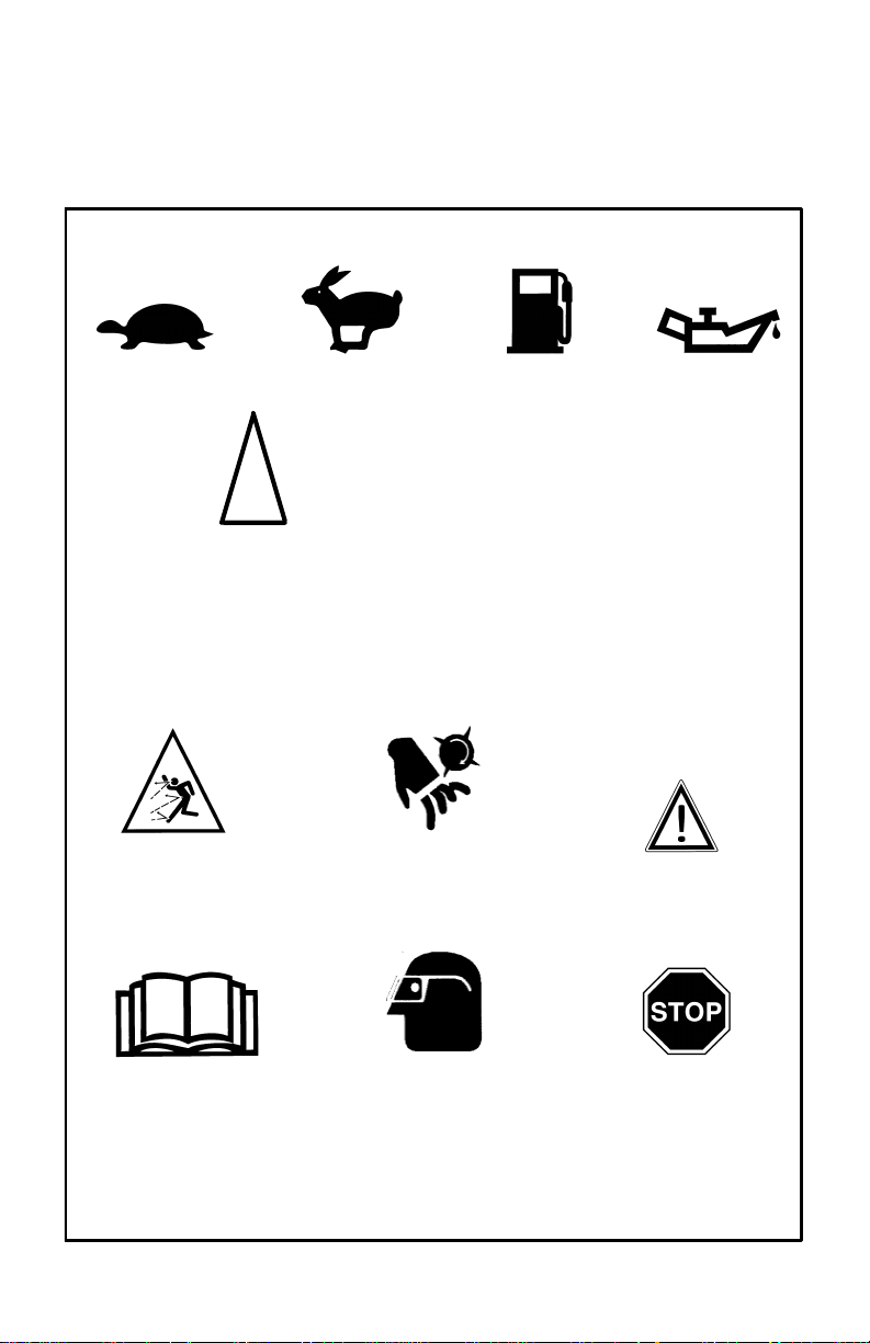
INTERNATIONAL SYMBOLS
IMPORTANT: Many of the following symbols are located on your unit or on literature supplied with the product. Before you operate the unit, learn and understand the purpose for
each symbol.
Control And Operating Symbols
Slow Fast
Choke OFF
Half Choke
Full Choke
Safety Warning Symbols
WARNING
Thrown Objects.
Keep Bystanders Away.
Disconnect Spark Wire Before
Fuel Oil
Rotating Parts. Stop Engine.
WARNING
Making Adjustments.
WARNING
IMPORTANT
Read Owner’s Manual
Before Operating
This Machine.
F-031306L
WARNING
Wear Eye Protection
6
STOP
Page 7
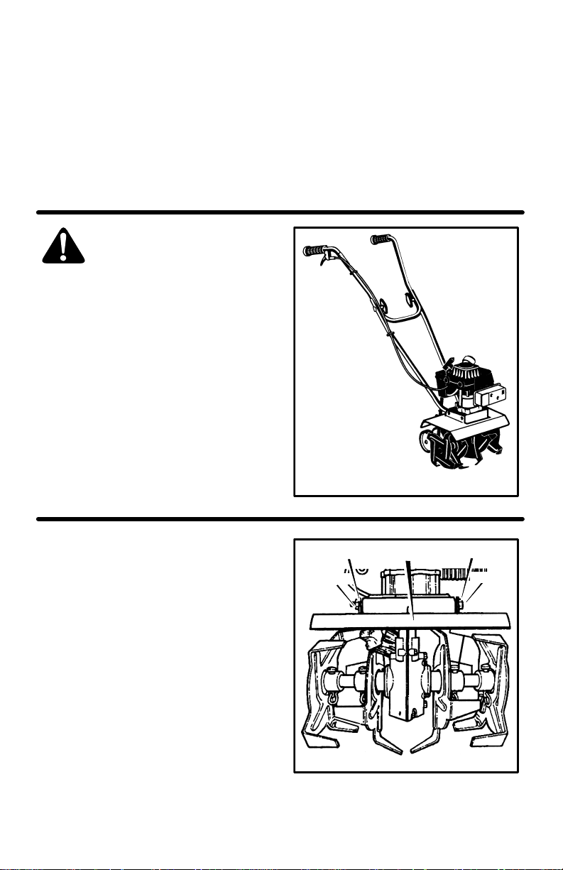
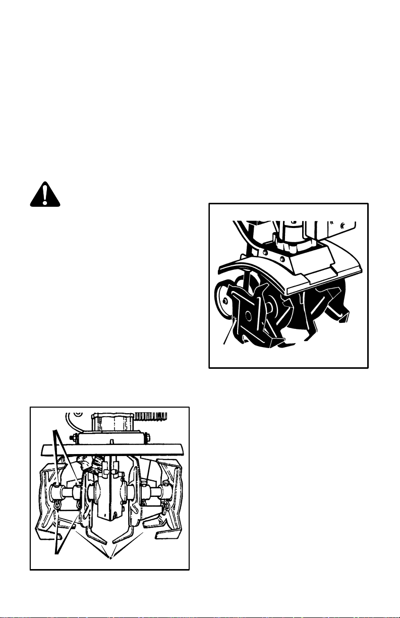
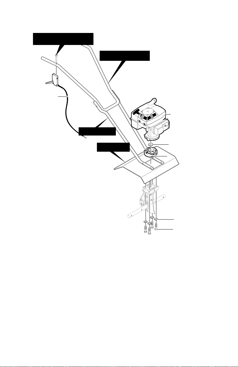
ASSEMBLY
-
ASSEMBLY
PARTS PACKED SEPARATELY
IN CARTON
1 - Owner’s Manual (not shown)
1 - Upper Handle
1 - Right Lower Handle
1 - Left Lower Handle
1 - Parts Bag
WARNING: Always wear safety
glasses or eye shields while as
sembling the cultivator.
Figure 1 shows the cultivator completely assembled.
References to the right or left side of the cultivator are from the viewpoint of the operator’s position behind the unit.
HOW TO REMOVE THE
CULTIVA TOR FROM THE CARTON
1. Remove the parts bag from the carton.
2. Remove the handles from the carton.
3. Remove the packing material positioned
around the unit.
4. Lift the cultivator out of the carton and
place on a hard level surface.
5. Remove the packing material from the
tines.
Figure 1
HOW TO
ASSEMBLE THE HANDLE
The lower handles have a short bend at the
bottom and have been flattened at the top.
1. Unwind the throttle control from around
the engine. Straighten the throttle cable.
Make sure that you do not bend or kink
the cable.
2. Remove the locknuts, spacers, and
screws from the tine shield (see
Figure 2).
F-031306L
7
Spacers
Locknuts
SpacersTine Shield
Bolts
Figure 2
Page 8
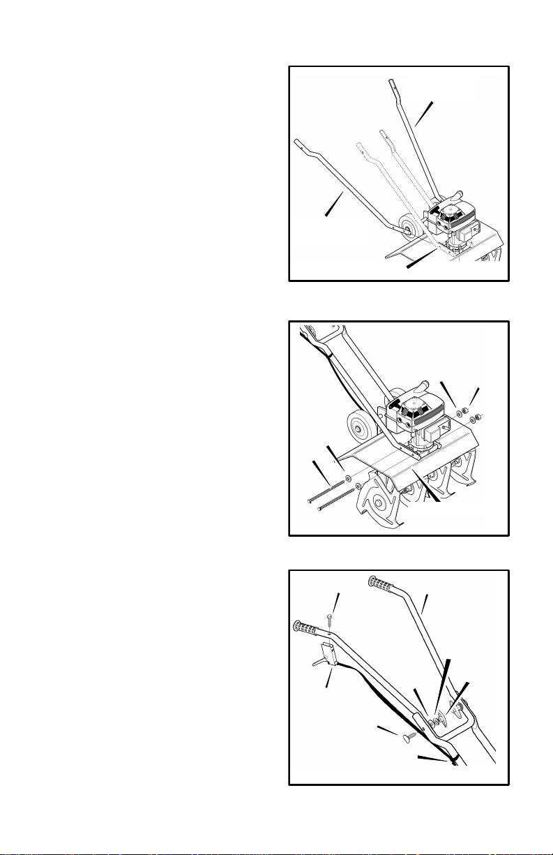
3. Insert the right lower handle into the
ASSEMBLY
mounting channel (see Figure 3). Make
sure the flat end at the top of the handle
is facing inward.
4. Mount a spacer on each screw. Push
the screws through the tine shield, the
lower handle, and half way through the
engine casing (see Figure 4).
5. Insert the left lower handle into the
mounting channel (see Figure 3). Make
sure the flat end at the top of the handle
is facing inward.
6. Push the screws through the engine
casing, the lower handle, and the tine
shield. Secure with spacers and locknuts as shown in Figure 4. Do not tight-
en at this time.
Right Lower
Handle
Mounting Channel
Left Lower
Handle
Figure 3
7. Remove the fasteners from the upper
handle (see Figure 5).
8. Assemble the upper handle to the lower
handles with the fasteners removed in
step 7.
9. Tighten the knobs.
NOTE: To tighten the knobs, hold the
curved carriage bolt head against the
outside of the lower handle as you
tighten the knobs.
10. Tighten the locknuts that hold the ends
of the lower handles (see Figure 4).
Tighten only enough to firmly hold the
handles.
CAUTION: Over tightening the locknuts can change the shape of the handle and damage the engine casing.
11. Mount the throttle control on the right
side of the upper handle with the screw
as shown in Figure 5.
12. Attach the throttle control cable to the
lower handle with the cable fastener.
Make sure the throttle control cable is
routed to the outside of the handles.
F-031306L
Spacer
Screw
Throttle Control
8
Screw
Carriage Bolt
Cable Fastener
Spacer
Tine Shield
Upper Handle
Curved
Washer
Locknut
Figure 4
Flat
Washer
Knob
Figure 5
Page 9

ASSEMBLY
n CHECKLIST
For the best performance and satisfaction
from this quality product, please review the
following checklist before you operate the
cultivator:
n All assembly instructions have been
completed.
n Check carton. Make sure no loose
parts remain in the carton.
n All fasteners have been properly tight-
ened.
As you learn how to use the cultivator, pay
extra attention to the following important
items:
nn Fuel tank is filled with a fresh, clean,
fuel mixture.
nn Become familiar and understand the
function of all controls. Before you
start the engine, operate all controls.
IMPORTANT: This unit is equipped with an internal combustion engine and must not be
used on or near any unimproved forest-covered, brush-covered or grass-covered land
unless the engine’s exhaust system is equipped with a spark arrester meeting
applicable local or state laws (if any). If a spark arrester is used, it must be maintained in
effective working order by the operator.
In the State of California the above is required by law (Section 4442 of the California
Public Resources Code). Other states may have similar laws. Federal laws apply on
federal lands. See an Authorized Service Center for a spark arrester for the muffler.
F-031306L
9
Page 10
OPERATION
KNOW YOUR CULTIVATOR
READ THE OWNER’S MANUAL AND ALL SAFETY RULES BEFORE YOU OPERATE the
cultivator. To familiarize yourself with the location of the controls, compare the illustrations with
your cultivator. Save this manual for future reference.
Throttle Control
Lever
Upper Handle
Lower Handle
Depth Stake and
Transport Wheels
Assembly
Depth Rod and
Transport Wheels
Assembly
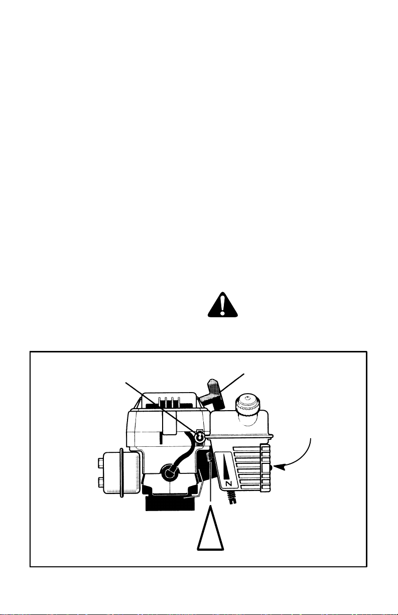
Throttle Control - Controls the engine
speed and the tine rotation. The cultivator is
equipped with a centrifugal clutch that engages the tine drive system when the engine
speed is increased.
Choke Control Lever - Use to assist
when starting a cold engine.
ON / OFF
Switch
Recoil Starter Handle
Choke Control
Air Cleaner
Fuel Cap
Tine Shield
Tines
Figure 6
Recoil Starter Handle - The engine is
equipped with an easy pull recoil starter.
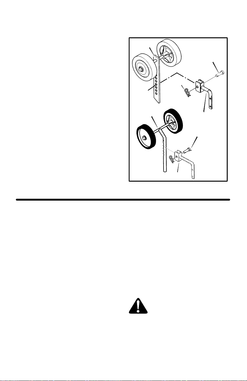
Depth Stake or Depth Rod - Two types
are shown. Mount with the wheels up to adjust the depth of cut. Also use to help control
the direction and speed of the cultivator.
ON / OFF Switch - The ON position al-
lows the engine to start. The OFF position
stops the engine and keeps the engine from
starting.
EYE PROTECTION
Always wear safety glasses. If you wear eye
glasses, put a Wide Vision Safety Mask over
your eye glasses.
F-031306L
Transport Wheels - Mount with the
wheels down when transporting the cultivator.
WARNING: Debris thrown from
the cultivator can result in for-
eign objects being thrown into
the eyes, which can cause severe eye
damage. Always wear safety glasses or
eye shields when operating the cultivator.
10
Page 11
OPERATION
HOW TO USE THE CULTIVATOR
How To Stop The Cultivator
1. Release the throttle control to stop the
tines.
2. Move the ON/OFF switch, on the engine,
to the OFF position.
How To Set The Depth
Your model will either have a depth stake or
a depth rod to control the tilling depth and
the forward speed. Set the depth stake or
the depth rod to the desired tilling position
as follows:
1. Remove the hairpin and the clevis pin
from the depth stake or depth rod (see
Figure 7).
2. Adjust the depth stake or depth rod up-
ward to dig shallower or downward to dig
deeper.
3. Reinstall the clevis pin and hairpin.
HOW TO
OPERATE THE CULTIVATOR
1. Start the engine. See “How To Start The
Engine”.
2. Tilt the unit back on the depth stake or
depth rod until the tines are off the
ground. Squeeze the throttle control all
the way up against the hand grip. The
engine is governor controlled and must
be run at full throttle while tilling.
3. Hold the handle firmly and slowly tilt the
unit forward to begin the tilling action.
4. As the tines begin to make contact with
the ground, hold back on the handles so
Depth
Stake
Clevis Pin
Hair Pin
Depth Rod
Depth Rod Bracket
that the tines will dig into the soil and not
ride forward over the ground.
5. Avoid tilling soil that is too dry as it will
pulverize and produce a dust that will not
hold water. Also, tilling soil that is too wet
will be hard on the machine and produce
unsatisfactory clods.
6. Lowering the depth stake will slow the
cultivator and make it till deeper. Raising
the depth bar will allow it to move faster
and till more shallow. See “How To Set
The Depth Stake or Depth Rod”.
WARNING: Keep away from the
rotating tines. Rotating tines
can cause injury.
Depth Stake
Bracket
Clevis Pin
Figure 7
F-031306L
11
Page 12

OPERATION
BEFORE STARTING THE ENGINE
How To Prepare The Engine
WARNING: Always use a safety
fuel container. Do not smoke
when adding the fuel mixture to
the engine. When inside an enclosure,
do not fill the fuel tank. Before you add
the fuel mixture, stop the engine. Let the
engine cool for several minutes.
How To Mix The Fuel Mixture
The two cycle engine, used on this cultivator,
requires a mixture of gasoline and oil for lubrication of the bearings and other moving
parts. The correct fuel mixture ratio is 24:1
(5.3 oz. oil per one gallon of gas - see the
Fuel Mixture Chart). Gasoline and oil must
be pre-mixed in a clean gasoline container.
Always use fresh, clean, unleaded gasoline.
Mix gasoline and oil as follows:
1. Pour one (1) U.S. quart of fresh, clean,
unleaded automotive gasoline into a one
gallon size gasoline container.
2. Add 5.3 ounces of clean, high quality,
two-cycle oil to the gasoline container.
IMPORTANT: Do not use outboard motor oil or multi-viscosity oils,such as
10W-30 or 10W-40.
3. Install the fuel cap onto the gasoline container. Vigorously shake the gasoline
container to mix the oil with the gasoline.
4. Add an additional three (3) U.S. quarts of
gasoline to the gallon container. Again
shake the gasoline container.
5. This completes the gasoline mixing procedure. The gasoline can now be added
to the fuel tank.
FUEL MIXTURE CHART (mixture 24:1)
U.S.
SI. (Metric
GAS OIL GAS OIL
1 Gal. 5.3 oz. 4 Liters .167 L
2 Gal. 11 oz. 8 Liters .333 L
5 Gal. 27 oz. 20 Liters .833 L
Do not fill the fuel tank with gasoline that does not have oil mixed in it. Shake the
gasoline container before each filling of the fuel tank.
Add more gas
(3 U. S. Quarts)
12
F-031306L
OIl
(5.3 oz)
Gasoline
1U.S.
Quart
1 U.S. Gallon container
Shake Can
1 U.S.
Gallon
Special
Gasoline
Page 13
OPERATION
-
HOW TO START THE ENGINE
Before you start the engine, make sure that
you have read and understand all the instructions on the preceding pages.
1. Fill the fuel tank to 1/2 inch below the
bottom of the fill neck. Reinstall the fuel
tank cap securely. Always use fresh fuel.
Never use fuel that could be stale from
long periods of storage.
2. Move the ON/OFF switch to the ON
position (see Figure 8).
3. If the engine is cold, move the choke
control to the Full Choke position (all the
way down).
NOTE: Do not choke a hot or warm
engine.
4. Put the unit firmly on the tines and depth
stake, or wheels, in an open area.
5. Hold the right handle firmly with your left
hand.
6. Hold the rope handle with your right
hand and pull to start the engine. Repeat
if necessary. (It is sometimes necessary
to hold the throttle control lever against
the hand grip with your left hand. As
soon as the engine starts, slowly release
the throttle control. If released too slowly,
the unit will sometimes move forward).
7. When the engine starts, move the choke
lever to the Half Choke position. When
the engine runs smoothly, move the
choke lever to the No Choke position.
NOTE: If the tines do not stop when
the throttle control is released, adjust
the carburetor idle speed. See “How
To Adjust The Carburetor” in the Service And Adjustments.
8. To stop the engine, release the throttle
control and move the ON/OFF switch to
the OFF position.
9. If the engine becomes flooded remove
and dry the spark plug. See “Spark Plug
Maintenance” in the Maintenance section of this manual. Then, pull the starter
rope with the choke lever in the No
Choke position.
WARNING: The muffler and sur
rounding areas become hot after running the engine. Avoid
these areas.
F-031306L
ON / OFF
Switch
Recoil Starter Handle
No Choke
Half Choke
Full Choke
Choke Control
13
Air Cleaner
Figure 8
Page 14

OPERATION
CULTIVATING TIPS
S Tilling is digging in, turning over and
breaking up packed soil before planting.
Loose unpacked soil helps root growth.
Best tilling depth is 4 to 6 inches. A tiller
will also clear the soil of unwanted vegetation. The decomposition of this vegetation matter enriches the soil. Depending
on the climate (rainfall and wind), it may
be advisable to till the soil at the end of
the growing season to further condition
the soil.
S Avoid tilling soil that is too dry as it will
pulverize and produce a dust that will not
hold water. Also, tilling soil that is too wet
will be hard on the machine and produce
unsatisfactory clods.
S If the cultivator stops forward motion and
tries to dig deeper than necessary, move
the handles from side to side to start forward motion.
S Cultivating is loosening or digging
around growing plants which allows the
plants to flourish.
S When using the cultivator to remove
weeds, it is best to cultivate no deeper
than 1-1/2 inches. Cultivating deeper will
only pull to the surface ungerminated
weed seeds. Raising the depth stake will
allow it to move faster and till more shallow.
S Better growth will be obtained if an area
is tilled properly and used soon after tilling to preserve the moisture content.
S The depth stake (on the back of the culti-
vator) serves a dual purpose. It helps
regulate the depth of the cut and also
acts as a brake to help the operator control the speed of the cultivator.
S Lowering the depth stake will slow the
cultivator and make it till deeper. Raising
the depth stake will allow it to move faster and till more shallow.
HINTS FOR DEPTH STAKE OR
WHEEL ADJUSTMENT
Light cultivation (about 1 to 2 inches
depth) with moderate growth
Adjust the wheels upward to their highest or
next to their highest position. Make sure the
handles are at a comfortable height for operating the cultivator.
S When cultivating around plants or close
areas, you may want to remove the outside tines. See “Tine Replacement” in
the Service/Adjustments section.
WARNING: Read the Owner’s
manual. Know location and
functions of all controls. Keep
all safety devices and shields in place.
Never allow children or uninstructed
adults to operate cultivator. Shut off engine before unclogging tines or making
repairs. Keep bystanders away from machine. Keep away from rotating parts
and tines. They can cause injury.
Seed bed preparation (4 to 6 inches
depth)
Use the depth stake. Adjust the depth stake
downward for deeper cultivation.
Heavy soil (4 inch depth or greater)
Remove the depth stake and work the tines
down with a back and forth motion to at least
a depth of 4 inches. Slowly pull the cultivator
backward allowing the soil to feed forward
over the tines.
F-031306L
14
Page 15

MAINTENANCE
CUSTOMER RESPONSIBILITIES
SERVICE RECORDS
Fill in dates as you
complete regular
service.
Tighten All Screws and
Nuts
Lubricate Tine Shaft
Lubricate Transmission
Check Spark Plug
Clean and Oil Air Cleaner
Filter
Clean Cylinder Exhaust
Ports
Drain Fuel
Before
Each
Use
√ √
PRODUCT SPECIFICATIONS
Model No.: See Nameplate
Date Of Purchase:
Horse Power: 2
Displacement: 3.0 cu. in.
Gasoline Capacity: 20 oz.
Fuel/Oil Mix Ratio: 24:1 Oil To Gas
Spark Plug: Champion
Spark Plug Gap: 0.035 inch
Idle RPM: 1700-3000
(49.2 cc.)
(5.3 oz. oil to 1 gal. gas)
(use unleaded regular)
RCJ-8Y
After
First
2
Hours
Every
Hours
Every
25
Hours
Before
75
Storage
Before
Each
Season
SERVICE
DATES
√ √
√ √
√ √
√
√
√
√
GENERAL RECOMMENDATIONS
The warranty on this cultivator does not cover items that have been subjected to operator abuse or negligence. To receive full value
from the warranty, the operator must maintain the cultivator as instructed in this
manual.
Some adjustments must be made periodically to properly maintain your cultivator.
All adjustments in the Service and Adjustments section of this manual must be
checked at least once each season.
F-031306L
15
Page 16
MAINTENANCE
LUBRICATION
Every 25 hours and/or at the beginning of
each season, make sure the gear box is
filled with lubricant (see Figure 9). Tubes of
gear lubricant are available from most automotive supply stores. Use portable tool
grease such as Lubriplate 630AA (Product
No. 06787, 1-3/4 oz. tube) or Lubriplate
GR-132 (Product No. 15892, 10 oz. tube).
After cleaning and before storage, apply oil
to the tine shaft (see Figure 9).
WARNING: Allow the transmission to cool before filling with
grease.
1. Remove both left side tines. See “How
To Replace The Tines” in the Service
and Adjustments section.
2. Remove the air vent screw (see
Figure 9).
3. Mount a grease gun onto the grease fit-
ting. Fill the transmission until the
grease begins to come out of the air vent
screw hole.
4. Reinstall the air vent screw.
5. Check the condition of the felt washer
(see Figure 9). Replace the felt washer
if it is damaged (see the Repair Parts
section in this manual).
6. Clean and lubricate the tine shaft with a
few drops of oil.
7. Reinstall the left side tines.
8. Remove the right side tines. Check the
felt washer for damage. Clean and oil
the tine shaft. Reinstall the right side
tines.
Air Vent Screw
Tine
Shaft
Felt
Washer
Grease Fitting
Figure 9
HOW TO CLEAN THE TINES
Always remove dirt and debris from the cultivator after each use. Remove any string,
wire or vegetation that may become lodged
in the mechanism and stop the tines from
rotating.
1. Release the throttle control and move
the on-off switch to the OFF position.
Disconnect the spark plug wire from the
spark plug.
2. While wearing gloves, remove the hair-
pins and clevis pins that secure the tine
assemblies to the shaft (see Figure 10).
Remove the tines from the shaft.
3. Remove any lodged debris from the
shaft and tines. Clean and lubricate the
tine shaft with a few drops of oil.
4. Reassemble the tines on the shaft and
secure with a clevis pin and hairpin.
F-031306L
5. Connect the spark plug wire to the spark
plug.
Clevis
Pins
16
Hair Pins
Tines
Figure 10
Page 17
MAINTENANCE
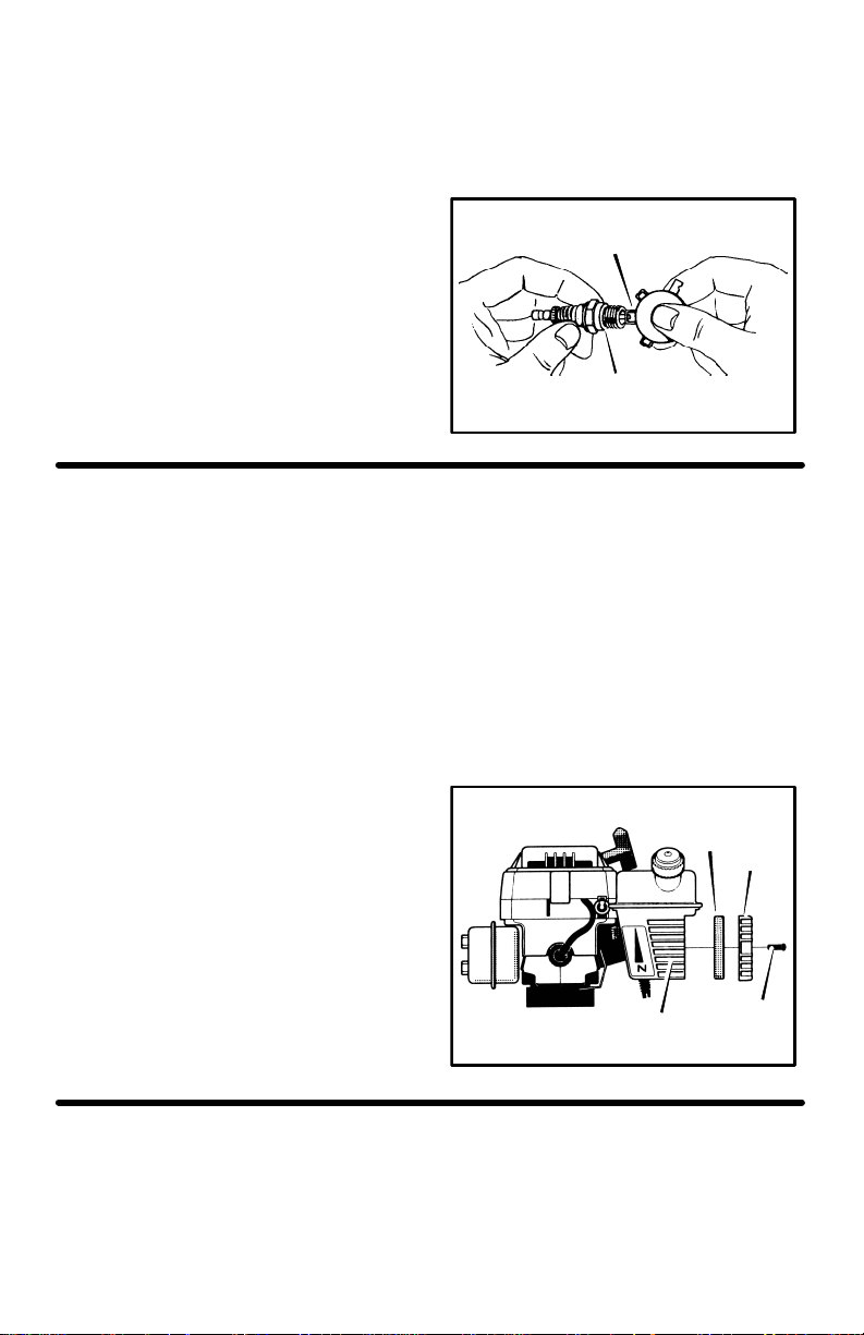
SPARK PLUG
Check the spark plug every 25 hours. Re-
place the spark plug if the electrodes are
pitted or burned or if the porcelain is
cracked.
1. Make sure the spark plug is clean.
Clean the spark plug by carefully scraping the electrodes (do not sand blast or
use a wire brush).
2. Check the spark plug gap with a feeler
gauge. See “Product Specifications” for
the correct spark plug gap and replacement spark plug.
3. Before installing the spark plug, coat
the threads lightly with oil for easy removal. Tighten the spark plug to a torque
of 15 foot-pounds.
Feeler Gauge
0.035”
Spark Plug
Figure 11
HOW TO CLEAN THE AIR FILTER
The engine uses a foam air filter that can be
cleaned and reused. Clean and oil the air
filter every 25 hours. Clean more often in
dusty conditions. Remove and clean the air
filter as follows:
CAUTION: Never run the engine without
the air filter installed. An air filter clogged
with dust can result in loss of engine
power and can cause excessive wear or
damage to the engine. If the air filter is
clogged, clean or replace immediately.
1. Disconnect the spark plug wire from the
spark plug.
2. Remove the screws from the air filter
cover (see Figure 12). Remove the air
filter cover and the air filter.
3. Wipe the cover and the inside of the air
filter housing with a clean cloth.
4. Clean the air filter in a solution of water
and household detergent. Rinse thoroughtly in clean water.
5. Wrap the air filter in a dry clean cloth.
Squeeze out (do not twist) all solution
until dry.
6. Cover the outside of the air filter with
oil. Use the same type of oil as used to
make the fuel mixture. Lightly squeeze
the air filter to distribute and remove
any excess oil.
7. Put the clean air filter into the air filter
housing.
8. Install the air filter cover and secure
with the screws as shown.
9. Connect the spark plug wire to the spark
plug.
Air Filter
Cover
Filter Housing
Screw
Figure 12
CYLINDER EXHAUST PORTS
Clean the cylinder exhaust ports after every
75 hours of operation. For this procedure, we
recommend that you take your unit to a Authorized Service Center.
F-031306L
17
Page 18
SERVICE AND ADJUSTMENT
HOW TO REMOVE AND INSTALL THE TINES
References to the right or left side of the cultivator are from the viewpoint of the operator’s position behind the unit.
All four tines are different and cannot be interchanged. The tines must be correctly
installed or the cultivator will not function
properly.
To till around plants or in small areas, the
outside tines can be removed to reduce the
tilling width to approximately 7 inches.
WARNING: The tines are self
sharpening and will become
carefully.
The tines will all wear evenly. If the tines are
being replaced because of wear, we recommend that all four tines be replaced at the
same time. To replace the tines, do the following:
quite sharp from use. Handle
Tine Removal
1. Put the on-off switch in the OFF position.
2. Disconnect the spark plug wire from the
spark plug.
3. While wearing gloves, remove the hair-
pins and clevis pins that secure the tine
assemblies to the shaft (see Figure 13).
Remove the tines from one side of the
unit.
Clevis
Pins
Tine Installation
1. Clean and lubricate the tine shaft with a
few drops of oil.
2. Place the inside tine on the tine shaft
and reinstall the clevis pin and hairpin.
3. When the tines are properly installed, the
letter R will be visible on the outside of
the right tine (see Figure 14). The letter
L will be visible on the outside of the left
tine.
R
Figure 14
4. Mount the outside tine on the tine shaft
and fasten with the clevis pin and hair-
pin (see Figure 13).
5. The cutting tips on the outside tines all
bend in toward the inside tine. When assembled correctly, the letter R on the
right side, or L on the left side, will be
visible from the outside of the unit.
Hair Pins
F-031306L
Tines
6. Repeat the above steps on the opposite
side of the unit.
NOTE: Make sure the tines are installed
on the correct side of the unit.
Figure 13
18
Page 19
SERVICE AND ADJUSTMENT
HOW TO ADJUST THE CARBURETOR
A dirty air cleaner will cause the engine to
run improperly or to smoke excessively. Before adjusting the carburetor, make sure the
air cleaner is clean. Never make unnecessary adjustments to the carburetor. The carburetor was set at the factory to operate
efficiently under most applications. However,
if adjustments are required, we recommend
you contact your nearest Authorized Service
Center. If you feel that you are competent to
make carburetor adjustment proceed as follows.
WARNING: Use extreme care
when making adjustments that
require the engine to be running. Keep hands, feet, hair and loose
clothing away from all moving parts.
1. Turn the mixture adjustment screw
clockwise to until closed (see Figure 15).
IMPORTANT: T o prevent damage to
the carburetor or to the adjusting
screw, tighten the adjustment screws
with your fingers.
2. Turn the mixture adjustment screw
counterclockwise one turn.
3. Start the engine and let it warm up for
approximately 3 to 5 minutes. Do not adjust the carburetor when the engine is
cold.
4. If the engine runs erratically or stops after the choke lever is moved to the
CHOKE OFF position, then open the
mixture adjustment screw an additional 1/8 turn counterclockwise.
5. With the engine running, release the
throttle control (idle position) to make the
mixture adjustments.
6. Slowly turn the mixture adjustment
screw clockwise until the engine begins
to run erratically. Note this position.
7. Then, slowly turn the mixture adjustment
screw counterclockwise until the engine
again begins to run erratically. Note this
position.
8. Turn the mixture adjusting screw clockwise until it is halfway between the first
position and the second position.
9. Check the engine idle speed. Start the
engine and release the throttle control. If
the tines do not turn with the throttle control is released, the idle speed is correct.
If the tines turn with the throttle control is
released, adjust the engine idle speed as
follows.
10. Have someone tilt the cultivator back on
its depth stake so that the tines are off
the ground.
11. Start the engine.
12. With the throttle in the released (idle
position), turn the idle speed adjust-
ment screw counterclockwise until the
tines stop rotating.
WARNING: The engine governor is set at the factory. Do not
Over speeding the engine above the factory setting can be dangerous. If you
think the engine governor needs an adjustment, contact your nearest Authorized Service Center.
Adjustment Screw
Engine Shown With Air Filter Removed
change the governor setting.
Carburetor
Idle Speed
Mixture
Adjustment Screw
Figure 15
F-031306L
19
Page 20

SERVICE AND ADJUSTMENT
-
-
STORAGE
WARNING: Never store the cul
tivator indoors with fuel in the
fuel tank. Never store in an enclosed, poorly ventilated area where
fumes could reach an open flame, a
spark or a pilot light as on a furnace, water heater or clothes dryer.
WARNING: Do not remove gas
oline while inside a building,
near a fire, or while you smoke.
Gasoline fumes can cause an explosion
or a fire.
When the cultivator is put in storage for thirty
days or more, follow the steps below to
make sure the cultivator is in good condition
the following season.
Cultivator
S Completely clean the cultivator.
S Remove the tines. Clean and apply oil to
the tine shafts. Mount the tines onto the
tine shafts. See “How To Remove And
Install The Tines” in the Service And Adjustments section.
S Loosen the knobs that secure the upper
handle to the lower handle. Carefully fold
the upper handle. Make sure the throttle
cable is not bent. Tighten the knobs.
S The cross piece of the upper handle (be-
tween the lower handles) can now be
used as a carry handle. To store the cultivator up off the floor and out of the way,
the cross piece can also be hooked over
a wall hook.
S Put the cultivator in a building that has
good ventilation.
S Cover the cultivator with a suitable pro-
tective cover that does not retain moisture. Do not use plastic.
IMPORTANT: Never cover the cultivator
while the engine and exhaust areas are
still warm.
NOTE: A yearly checkup or tune-up by a
Authorized Service Center is a good way
to make sure that your cultivator will provide maximum performance for the next
season.
Engine
IMPORTANT: It is important to prevent
gum deposits from forming in fuel system
parts such as the carburetor, fuel filter,
fuel hose, and tank during storage. Also,
using alcohol-blended fuels (called gasohol, ethanol or methanol) can attract
moisture which leads to separation and
formation of acids during storage. Acidic
gas can damage the fuel system of an engine while in storage.
To prevent engine damage when the cultivator is in storage for 30 days or more, follow
the steps below:
S Let the engine run until it is out of gaso-
line.
S Slowly pull the starter handle until you
feel resistance due to compression in
the cylinder, then stop.
S Slowly release the starter rope. This
position will close both the intake and the
exhaust ports and help prevent corrosion
of the piston and cylinder.
F-031306L
20
Page 21

TROUBLE SHOOTING CHART
Engine runs erratically
or
TROUBLE CAUSE CORRECTION
Engine difficult to start
or
Engine runs erratically
Engine will not run at full
speed
Engine speed does not
increase properly
Engine smokes
excessively
Tines continue to rotate
when throttle control is
released
Tines will not turn Debris lodged in tine Remove debris. See “How
Stale fuel mixture Drain fuel tank. Fill with fresh
Too much oil in fuel mixture Check fuel mixture chart and
Dirt in fuel tank or out of fuel Clean fuel tank.
Carburetor out of adjustment See Carburetor Adjustment
Fouled spark plug Clean and set spark plug
Dirty air filter Clean and oil air filter.
Debris interfering with throttle
linkage
Plugged air filter
Too much oil in fuel mixture
Carburetor out of adjustment Adjust carburetor idle speed.
fuel mixture.
mix fresh fuel.
section.
gap.
Clean dirt and debris of top
of carburetor.
Clean and oil air filter.
Check fuel mix chart and mix
fresh fuel.
See “How To Adjust The
Carburetor” in the
Maintenance section.
To Clean The Tines” in the
Maintenance section.
Unit does not till properly Incorrect tine installation Check the tines for proper
F-031306L
installation. See “How To
Remove And Install The
Tines” in the Service And
Adjustments section.
21
Page 22
THROTTLE
17
REF.
MOUNT SCREW
MODEL 11052x4D
REF.
UPPER HANDLES
REF.
LOWER HANDLES
10
KEY
PART NO. DESCRIPTION
NO.
10 2.0HP Engine
11 56694 Flat washer
12 335350 Rotor
13 120380 Washer
REF.
TINE SHIELD
11
12
13
14
323392C
KEY
PART NO. DESCRIPTION
NO.
14 1x90 Screw
17 319306 Cable, Throttle
-- F-031306L Instruction Manual
F-031306L
22
Page 23

312
MODEL 11052x4D
310
311
300
F-031306L
KEY
PART NO. DESCRIPTION
NO.
300 1901017 Transmission
310 339390E701 Bracket, Depth Rod
311 180024 Screw, 1/4-20x1.25
312 782585 Nut, 1/4-20
23
318848C
Page 24

MODEL 11052x4D
483
482
480
482
485
484
493
496
494
KEY
PART NO. DESCRIPTION
NO.
480 7401015 * Shield, Tine *
481
490
495
490
496
491
KEY
PART NO. DESCRIPTION
NO.
491 56157E701 Tine Assy. Inner LH
496
492
494
495
323393A
481 310056 Screw, 1/4-20x5.50
482 672734 Spacer, Flange
483 782585 Nut, 1/4-20
484 48x894 Decal, Murray
485 48x4031 Decal, Caution
490 56158 Washer, Felt
* Includes Key Nos. 484, 485 and four Key Nos 482.
F-031306L
492 56155E701 Tine Assy. Outer LH
493 56156E701 Tine Assy. Inner RH
494 56154E701 Tine Assy. Outer RH
495 56123 Clevis Pin
496 0031x4 Hair Pin
24
Page 25

663
MODEL 11052x4D
660
650
661
662
F-031306L
KEY
PART NO. DESCRIPTION
NO.
650 331176 Z Wheel Support Assy.
660 56123 Clevis Pin
661 31x4 Hair Pin
662 338307 Tire & Rim
663 73664 Push On Nut
25
323396B
Page 26

MODEL 11052x4D
946
REF.
THROTTLE CONTROL
947
950
943
941
930
948
944
942
932
934
949
319375C
KEY
PART NO. DESCRIPTION
NO.
930 7401025 * Upper Handle *
932 339398E701 Lower Handle LH
934 7401022 * Lower Handle RH +
941 56199 Bolt 5/16-18x1.63
942 783000 Formed Washer
943 120393 Flat washer
944 1901018 T Knob
* Includes Key No. 950
+ Includes Key No. 949
F-031306L
KEY
PART NO. DESCRIPTION
NO.
946 56778 Hand Grip
947 426635 Screw 10-16x1.5
948 712267 Cable Tie
949 305828 Decal, Caution
950 48x4030 Decal, Throttle
Control
26
Page 27

Only use a factory repair part. Repair parts, except for the engine or the transmission, are available from the store where
HOW TO ORDER REPAIR PARTS
the unit was purchased, a service shop recommended by the store, or an authorized service shop found in the yellow
pages of the telephone directory. If you cannot get a repair part or service as described above, call or write to the Central
Parts Distributor shown below. When you order, include the following information: (1) Complete Model Number (see
nameplate), (2) Date of Manufacture, (3) Complete Part Number, (4) Description, (5) Quantity.
Repair parts for the engine or the transmission are available from the manufacturer’s authorized service center found
in the yellow pages of the telephone directory. See the individual engine or transmission warranties.
MURRAY, INC. LAWN MOWER CENTRAL PARTS DISTRIBUTORS
BILLIOU’S, INC.
1343 South Main St.
Porterville, CA. 93257
(559)784−41021−877−245−5468
FAX 1−800−266−7337
Arizona, California, Hawaii,
Nevada
BROWN & WISER, INC.
9991 S.W. Avery Street
Tualatin, OR. 97062
(503)692−03301−800−882−4782
FAX (503)691−2041
Alaska, Idaho (counties Ada,
Adams, Benewah, Boise, Bonner,
Boundry, Canyon, Clearwater,
Elmore, Gem, Idaho, Kooten,
Latah, Lewis, NEZ Perce, Owyee,
Payette, Ravalli, Shoshone, Valley,
Washington), Montana (counties
Flathead, Lake, Lincoln, Mineral,
Missoulo, Ravalli, Sanders),
Oregon, Washington
CPT CANADA POWER
TECHNOLOGY LIMITED
Mississauga
161 Watline Avenue
Mississauga, Ontario
L4Z−1P2
(905)890−69001−800−861−9559
Edmonton
101−10411−178 Street
Edmonton, Alberta
T5S 1R5
(780)453−57911−800−861−9559
Ville St−Laurent
234 Migneron Street
Ville St−Laurent, Quebec
H4T 1Y7
(514)731−35591−800−861−9559
Canada
F-031306L
FRANK EDWARDS CO.
3626 Parkway Blvd.
West Valley City, UT 84120
1−800−318−0201
FAX (801)736−8067
Colorado, Idaho (counties
Bannock Bearlake, Bingham,
Blaine, Booneville, Butte, Camas,
Caribou, Cassia, Custer, Franklin,
Fremont, Gooding, Jefferson,
Jerome, Lemhi, Lincoln, Madison,
Minidoka, Oneida, Power, Teton,
Twin Falls) Montana (all counties
except Flathead, Lake, Lincoln,
Mineral, Missoulo, Ravalli,
Sanders), Utah, Wyoming
GARDNER, INC.
1150 Chesapeake Ave.
Columbus, OH. 43212
1−800−848−8946
FAX (614)486−7122
Alabama, Arkansas, (except these
counties: Hempstead, Howard,
Lafayette, Little River, Miller,
Nevada, Pike, Sevier),
Connecticut, Delaware, District
of Columbia, Florida, Georgia,
Illinois (South of Hwy. 80),
Indiana, Iowa, Kansas, Kentucky,
Louisiana, Maine, Maryland,
Massachusetts, Michigan (except
upper Peninsula), Mississippi,
Missouri, Nebraska, New
Hampshire, New Jersey, New
York, North Carolina, Ohio,
Pennsylvania, Rhode Island,
South Carolina, Tennessee,
Vermont, Virgina, West Virginia
Puerto Rico
GULF COAST ENGINE, INC.
4202 Russell Dr.
Corpus Christi, TX. 78408
1−800−825−6999
FAX (888)888−7036
Arkansas (counties Hempstead,
Howard, Lafayette, Little River,
Miller, Nevada, Pike, Sevier) New
Mexico, Oklahoma, Texas,
Mexico
WISCONSIN MAGNETO
4727 N. Teutonia Ave.
Milwaukee, WI. 53209
1−800−733−7388
FAX 1−800−733−0127
Illinois (N. of Hwy. 80), Michigan
(upper Peninsula), Minnesota,
North Dakota, South Dakota,
Wisconsin
Page 28

NOTES
F-031306L
28
Page 29

MURRAY, INC. Garantie limitée de deux ans
Murray, Inc. garantit au premier acheteur que ce produit est exempt de vice de matériel et de fabrication
en condition d’usage normal pour une période de deux (2) ans à partir de la date d’achat. Toutefois, cette
garantie ne couvre pas les moteurs, accessoires (tels que souffleuses, lames de chasse-neige, sacs à
herbe et socs), les transmissions, accumulateurs et pièces d’usure normale (sauf indication ci-dessous)
et ne couvre pas les boîtes-pont puisque les entreprises qui fabriquent ces dispositifs offrent leur propre
garantie ainsi qu’un service par l’intermédiaire de leurs représentants autorisés. Pour toute information
complémentaire veuillez consulter les garanties qui couvrent ces pièces. Si vous n’êtes pas sûr que votre
machine comprennent ou soit équipée d’une ou de plusieurs de ces pièces, consultez votre concessionnaire avant tout achat. Vu les modalités et conditions indiquées par cette garantie limitée, nous réparerons
ou remplacerons à notre choix et sans frais pour le premier acheteur toute pièce couverte par cette garantie limitée pendant la période en vigueur.
Dans le cas où l’accumulateur présentait un défaut dans les quatre-vingt-dix (90) jours à compter de la
date d’achat, nous la remplacerions gratuitement. Si l’accumulateur présente un défaut après quatrevingt-dix (90) jours, mais avant cent vingt (120) jours à compter de la date d’achat nous la remplacerons
pour la moitié du prix de vente au détail en cours au moment de la demande d’échange.
Les pièces d’usure normale comprennent les courroies, lames, adaptateurs de lames, pneumatiques,
phares et couvre-sièges. Ces pièces sont garanties contre tout vice de matériel et de fabrication au moment de la livraison avec le produit. Toute réclamation pour la réparation ou le remplacement des pièces
d’usure normale doit se faire dans les trente (30) jours à compter de la date d’achat. Aucune réclamation
concernant les dommages entraînés par l’usage, l’abus ou la mauvaise utilisation du matériel ne sera
honorée.
Cette Garantie limitée Murray, Inc. de deux (2) ans est votre seul recours. Toutefois cette garantie est
nulle ou ne s’applique pas à toute machine ayant fait l’objet d’une intervention non autorisée, ayant été
modifiée, louée, utilisée de manière abusive ou à des fins commerciales ou professionnelles (non-résidentielles). Votre garantie ne couvre pas les réglages mécaniques mineurs qui ne proviennent pas d’un
vice de matériel ou de fabrication. Pour obtenir de l’aide afin de procéder à ces réglages, consultez votre
manuel.
Pour toute réclamation dans le cadre de cette garantie limitée de deux (2) ans Murray, Inc., rapportez
la machine (ou la pièce défecteuse dans le cas d’une autorisation préalable) ainsi que votre preuve d’achat à une station technique autorisée proche de votre domicile. Pour trouver la station technique autorisée la plus proche, appellez le centre régional de distribution de pièces détachées indiqué sur la liste fournie avec votre machine ou consultez l’annuaire. Si vous renvoyez la machine dans son entité, nous la
réparerons. Si nous autorisons seulement le renvoi de la pièce défectueuse, nous la remplacerons ou
la réparerons. Dans le cas d’un défaut de la boîte de transmission ou de l’engrenage différentiel (par opposition à la boîte-pont), toute la transmission ou le différentiel doit être renvoyé car ce dispositif ne contient pas de pièces réparables par l’utilisateur.
Cette garantie limitée Murray, Inc. de deux (2) ans vous confère des droits juridiques précis et il se peut
que vous disposiez d’autres droits qui varient d’une juridiction à une autre. Cette garantie limitée est
fournie au lieu de toute autre garantie expresse ou implicite
alité marchande et d’aptitude à un usage particulier. Pour toute information complémentaire au sujet
de cette garantie écrite ou pour obtenir de l’aide, appellez au numéro ou écrivez à l’adresse indiqués cidessous. Le numéro du modèle ainsi que le numéro 1-800 du SERVICE À LA CLIENTÈLE est indiqué
sur la plaque du numéro de modèle fixé à la machine.
MURRAY, INC.
Outdoor Power Equipment
Customer Service Department (Service Clientèle)
P.O. Box 268
Brentwood, Tennessee 37027, USA
y compris la garantie implicite de qu-
F-031306L
29
Page 30

INFORMATIONS S’ADRESSANT À L’USAGER
Ce livret d’instructions est destiné aux individus ayant une certaine compétence technique. Comme pour la plupart des manuels de service, certaines étapes ne sont pas décrites. Les étapes qui
indiquent la manière de desserrer ou de serrer des attaches sont des étapes que toute personne
ayant une certaine compétence technique peut accomplir. Lisez et suivez ces instructions avant
d’utiliser la machine.
Familiarisez-vous avec votre machine : Une bonne connaissance de la machine et de son
fonctionnement vous permettra d’en obtenir la meilleure performance. Tout en lisant ce manuel,
comparez les illustrations avec la machine. Apprenez l’emplacement et la fonction des commandes. Pour éviter tout accident, respectez les consignes d’utilisation et les règles de sécurité.
Conservez ce manuel comme référence à l’avenir.
IMPORTANT : un grand nombre de modèles sont vendus non montés dans un emballage en carton. Il incombe au propriétaire de la machine de s’assurer que les instructions de montage présentées dans ce manuel sont suivies à la lettre. D’autres modèles sont vendus déjà montés. Pour les
modèles montés, il incombe au propriétaire de vérifier le bon assemblage de sa machine. Avant
toute utilisation, le propriétaire doit inspecter la machine conformément aux instructions présentées dans ce manuel.
RESPONSABILITÉS DU PROPRIÉTAIRE
Il incombe au propriétaire de suivre les instructions ci-dessous :
1. Lire soigneusement et respecter les règles de sécurité.
2. Se conformer aux instructions pour l’assemblage et la préparation.
3. Inspecter la machine.
4. S’assurer que l’utilisateur de la machine connaît la façon correcte d’utiliser l’équipement standard et tous les accessoires.
5. N’utiliser la machine que lorsque les dispositifs de sécurité (carters, écrans, etc.) sont en place
et fonctionnent correctement.
6. Régler la machine comme il convient.
7. La machine ne doit être réparée qu’avec des pièces réglementaires ou agréées.
8. Effectuer chacune des opérations de maintenance obligatoires concernant la machine.
F-031306L
Les gaz d’échappement du moteur, certains
éléments de leur c omposition, a insi q ue c ertains
organes du véhicule contiennent ou émettent
des substances chimiques qui, selon l’État de
Californie, peuvent causer le cancer, des
malformations à la naissance, ou représentent
un danger pour la reproduction.
Les bornes et pôles de batterie et autres
accessoires de ce type contiennent du plomb et
des composés de plomb, substances chimiques
qui, selon l’État de Californie, peuvent causer le
cancer, des malformations à la naissance, ou
représentent un danger pour la reproduction.
30
Page 31

RÈGLES DE SÉCURITÉ
Règles de sécurité pour l’utilisation de la motobineuse
ATTENTION : La présence de ce symbole indique d’importantes précautions à prendre. Il signifie : “Attention ! Soyez vigilant ! Votre sécurité est en
jeu.”
ATTENTION : Pour prévenir
tout démarrage accidentel lors
du montage, du transport, du
réglage ou de la réparation de la machine, débranchez toujours la bougie et éloignez le fil de tout contact avec celle-ci.
IMPORTANT : Les normes de sécurité requiè-
rent que la machine soit équipée d’un détecteur
de présence de l’utilisateur afin de minimiser
les risques de blessures. Votre machine est
équipée de ce dispositif. Il ne faut dans aucun
cas tenter de désactiver le fonctionnement du
détecteur de présence.
Avant toute utilisation
S Lisez attentivement le manuel de l’utilisa-
teur. Familiarisez-vous bien avec les commandes et l’utilisation correcte de la
motobineuse. Sachez arrêter la motobineuse et rapidement en débrayer les commandes.
S Ne conduisez pas la motobineuse sans
porter des vêtements appropriés. Portez
des chaussures antidérapantes pour ne
pas glisser sur les surfaces glissantes.
S Éloignez toute personne de la zone de tra-
vail, en particulier les enfants et les animaux domestiques de petite taille.
S Inspectez attentivement la zone de travail
envisagée et retirez tout corps étranger.
S Sachez que le conducteur ou l’utilisateur
est tenu seul responsable de tout accident
ou dommage causé aux autres, à leur propriété et à lui-même.
S Débrayez et mettez le levier de vitesse au
point mort avant de démarrer le moteur.
Précautions pour le carburant
S Manipulez le carburant avec prudence car
il est très inflammable.
S Utilisez un récipient agréé.
S Vérifiez la quantité d’essence avant cha-
que utilisation, en veillant à laisser de l’es-
F-031306L
pace pour l’expansion de l’essence par la
chaleur du moteur ou du soleil.
S Remplissez le réservoir en plein air et avec
grande précaution. Ne fumez pas en remplissant le réservoir. Ne remplissez jamais
le réservoir d’essence à l’intérieur d’un bâtiment. Refermez bien le bouchon du réservoir d’essence et essuyez toute coulure
d’essence.
S En cas d’épanchement de carburant, ne
tentez pas de démarrer le moteur mais retirez la machine de l’endroit où a été renversé le carburant et évitez de créer toute
source d’inflammation jusqu’à la dissipation
complète des vapeurs d’essence.
S Ne retirez jamais le bouchon du réservoir
d’essence et n’ajoutez jamais de carburant
quand la machine fonctionne ou quand le
moteur est chaud.
S N’entreposez jamais du carburant ou une
motobineuse contenant du carburant dans
un bâtiment où les vapeurs d’essence peuvent atteindre une flamme.
Sécurité d’utilisation
S Ne laissez jamais des enfants ou de jeu-
nes adolescents utiliser la motobineuse.
Gardez-les à distance lors de l’utilisation
de la motobineuse. Ne laissez jamais des
adultes conduire la motobineuse sans instructions appropriées.
S N’utilisez jamais cette machine sous l’in-
fluence de drogues ou de médicaments
pouvant susciter la somnolence ou altérer
votre aptitude à la conduire.
S N’utilisez jamais cette machine si vous
êtes mentalement ou physiquement inapte
à la conduire en toute sécurité.
S Portez toujours des lunettes ou une visière
de protection lors de l’utilisation, du réglage
ou de la réparation de la motobineuse afin
de protéger vos yeux de tout corps étranger pouvant en être projeté.
S Ne placez pas les mains ou les pieds à
proximité des pièces rotatives.
S Soyez très prudent lors de l’utilisation de la
machine sur les allées en gravier, les pas-
31
Page 32

sages et les routes ou en les traversant.
RÈGLES DE SÉCURITÉ
Prenez garde à tout obstacle caché ou à la
circulation.
S Prenez soin de ne pas glisser ou tomber.
S Ne conduisez jamais la machine sans que
tous les carters, écrans ou autres dispositifs de protection soient en place.
S N’utilisez que des dispositifs et accessoires
approuvés par le fabricant de la machine
(tels que masses d’équilibrage, contrepoids et accessoires similaires).
S Ne conduisez jamais la motobineuse en
vitesse de marche rapide sur des surfaces
dures ou glissantes. Regardez vers l’arrière et soyez prudent en reculant.
S Ne permettez jamais aux personnes avoisi-
nantes de s’approcher de la motobineuse.
S Éloignez les enfants et les animaux de
compagnie lors de l’utilisation de la motobineuse.
S Ne conduisez jamais la motobineuse sous
un faible éclairage ou sans bonne visibilité.
S Soyez prudent lorsque vous cultivez un
terrain dur. Les dents peuvent s’accrocher
dans le sol et pousser la motobineuse en
avant. Si cela se produit, lâchez le guidon
et n’essayez pas de retenir la machine.
S Soyez très prudent en mettant la machine
en marche arrière ou en la tirant vers vous.
S Ne modifiez pas le réglage du régulateur
de régime et ne faites pas fonctionner le
moteur en survitesse.
S Démarrez ou allumez le moteur avec pru-
dence conformément aux instructions et
gardez les pieds à bonne distance des lames.
S Ne soulevez et ne transportez jamais la
machine lorsque le moteur est en marche.
S Ne faites pas tourner le moteur à l’intérieur
d’un bâtiment. Les fumées d’échappement
sont dangereuses et contiennent de l’OXYDE DE CARBONE, un gaz INODORE ET
MORTEL.
S Prenez toutes les précautions possibles
avant de laisser la motobineuse sans surveillance. Arrêtez le moteur et, si elle en
est équipée, retirez la clé.
F-031306L
S Ne surchargez pas la capacité de la moto-
bineuse en tentant de labourer trop profondément et trop vite.
Sécurité d’entreposage
S Consultez toujours le manuel de l’utilisa-
teur pour les détails importants à connaître
si vous allez entreposer la motobineuse
pendant un certain temps.
S Ne stockez jamais une motobineuse dont
le réservoir contient du carburant dans un
bâtiment où se trouve des sources d’ingnition telles que chauffe-eau, chauffage
d’appoint, sèche-linge, etc. Laissez refroidir le moteur avant d’entreposer la motobineuse dans un endroit clos.
S S’il est nécessaire de vider le réservoir de
son carburant, effectuez cette opération à
l’extérieur.
S Maintenez la motobineuse en bon état de
marche. Vérifiez le serrage correct des
fixations à intervalles réguliers.
Sécurité des réparations et du réglage
S Après avoir heurté un corps étranger, arrê-
tez le moteur. Débranchez la bougie et
éloignez le fil de tout contact avec celle-ci
afin d’éviter tout démarrage accidentel. Inspectez soigneusement la motobineuse
pour voir s’il y a des dégâts, puis réparez
tout dommage avant de redémarrer et de
conduire la machine.
S Si la motobineuse se met à vibrer de ma-
nière anormale, arrêtez le moteur et cherchez immédiatement la cause de cette
vibration. Une vibration signale généralement un problème.
S Arrêtez toujours le moteur avant de quitter
la position de travail. Débranchez aussi la
bougie avant de nettoyer les dents et avant
de procéder à une réparation, un réglage
ou une inspection.
S Lors du nettoyage, de la réparation ou de
l’inspection, arrêtez le moteur et vérifiez
que toutes les pièces mobiles se soient arrêtées.
S Ne tentez jamais d’effectuer des réglages
lorsque le moteur est en marche, sauf en
cas de recommandation spécifique du fabricant.
32
Page 33

RÈGLES DE SÉCURITÉ
SYMBOLES INTERNATIONAUX
IMPORTANT : Un grand nombre des symboles suivants se trouvent sur votre machine ou
dans la documentation fournie avec le produit. A vant d’utiliser la machine, apprenez et comprenez la signification de chaque symbole.
Symboles de commandes et de fonctionnement
Lent Rapide
Starter fermé
Mi-starter
Plein starter
Symboles de sécurité
ATTENTION DANGER
Projection d’objets.
Éloignez toute personne
de la zone de travail.
Carburant
ATTENTION DANGER
Pièces rotatives. Arrêter le
moteur. Débranchez le fil de la
bougie avant tout réglage.
Huile
ATTENTION
DANGER
IMPORTANT
Lisez le manuel de
l’utilisateur avant
toute utilisation
de cette machine.
F-031306L
ATTENTION DANGER
Chaussez des lunettes
de protection oculaire
33
STOP
Page 34

MONTAGE
MONTAGE
PIÈCES EMBALLÉES SÉPARÉMENT DANS LE CARTON
1 - Manuel de l’utilisateur (non représenté)
1 - Manche supérieur
1 -Manche inférieur droit
1 - Manche inférieur gauche
1 - Sac de pièces
ATTENTION : Utilisez toujours
une protection des yeux pen-
dant le montage de la motobineuse.
Figure 1 présente la motobineuse entièrement assemblé.
Les références aux côtés droit ou gauche de
la motobineuse se font du point de vue de
l’utilisateur aux commandes de la machine.
DÉBALLAGE DE LA
MOTOBINEUSE
1. Retirez le sac de pièces du carton.
2. Retirez les manches du carton.
3. Retirez les matériaux d’emballage entourant la machine.
4. Soulevez la motobineuse hors du carton
et placez-le sur une surface dure et plane.
5. Retirez les matériaux d’emballage qui
protègent les dents.
Figure 1
MONTAGE DES MANCHES
Les manches inférieurs ont leur extrémité
supérieure aplatie et leur extrémité inférieure
courbée sur une courte longueur.
1. Dégagez le câble d’accélérateur enroulé
autour du moteur. Redressez le câble
d’accélérateur. Veillez à ne pas le plier
ou l’entortiller.
2. Retirez les contre-écrous, les rondel-
les et les vis de de l’écran protecteur
des dents (voir Figure 2).
F-031306L
34
Rondelles
Contre-
écrous
Écran protecteur
des dents
Rondelles
Boulons
Figure 2
Page 35

MONTAGE
3. Insérez le manche inférieur droit dans
la colonne de montage (voir Figure 3).
Vérifiez que le bout plat en haut du manche est dirigé vers l’intérieur.
4. Placez une rondelle sur chaque vis. En-
foncez les vis à travers l’écran des
dents, le manche inférieur, et à moitié
dans le boîtier du moteur (voir Figure 4).
5. Insérez le manche inférieur gauche
dans la colonne de montage (voir
Figure 3). Vérifiez que le bout plat en
haut du manche est dirigé vers l’intérieur.
6. Enfoncez les vis à travers le boîtier du
moteur, le manche inférieur, et l’écran
des dents. Fixez avec les rondelles et
les contre-écrous comme indiqué à la
Figure 4. Ne serrez pas pour l’instant.
7. Retirez les attaches du manche supé-
rieur (voir Figure 5).
8. Assemblez le manche supérieur aux
manches inférieurs avec les attaches
retirées à l’étape 7.
9. Serrez les boutons.
le câble d’accélérateur est passé du côté
extérieur des manches.
Manche infé-
rieur gauche
Manche infé-
rieur droit
Colonne de montage
Rondelle
Rondelle
Vis
Figure 3
Contre-
écrou
REMARQUE : Pour serrer les boutons,
tenez la tête du boulon à tête ronde
courbé appuyée sur la face externe du
manche inférieur tout en serrant.
10. Serrez les contre-écrous qui retiennent
les extrémités des manches inférieurs
(voir Figure 4). Serrez juste assez pour
tenir fermement les manches en place.
ATTENTION : En serrant trop les
contre-écrous vous risquez de déformer le manche et d’endommager le boîtier du moteur.
11. Montez la commande des gaz sur le
côté droit du manche supérieur avec la
vis comme indiqué à la Figure 5.
12. Attachez le câble d’accélérateur au manche inférieur avec la bride. Vérifiez que
F-031306L
35
Vis
Commande
des gaz
Boulon à tête
ronde
Bride de câble
Écran protecteur
des dents
manche supérieur
Rondelle
d’appui
courbée
Figure 4
Rondelle
plate
Bouton
Figure 5
Page 36

MONTAGE
n LISTE DE VÉRIFICATION
Pour obtenir les meilleures performances de
cette machine et une satisfaction maximale,
veuillez passer en revue la liste de vérification qui suit avant d’utiliser la motobineuse.
n Toutes les instructions de montage
ont été suivies.
n Vérifiez l’emballage. Veillez à ce qu’il
ne reste aucune pièce dans le carton
d’emballage.
n Toutes les fixations ont été correcte-
ment serrées.
En apprenant à utiliser la motobineuse, prêtez une attention particulière sur les éléments importants indiqués ci-dessous.
nn Le réservoir d’essence doit être rempli
d’un mélange de carburant propre et
frais.
nn Familiarisez-vous et comprenez bien
la fonction de toutes les commandes.
Avant de démarrer la machine, utilisez toutes les commandes.
IMPORTANT : cette machine est équipée d’un moteur à combustion interne et ne doit
pas s’utiliser sur terrain forestier, buissonnant ou herbeux non préparé, à moins que le
système d’échappement du moteur ne soit équipé d’un pare-étincelles conforme à la
réglementation en vigueur s’il y a lieu. Dans le cas de l’utilisation d’un pare-étincelles,
celui-ci doit être maintenu en parfait état de marche par l’utilisateur.
En Californie, cette précaution est rendue obligatoire par la loi (section 4442 du
California Public Resources Code). Des réglementations similaires peuvent s’appliquer
dans d’autres juridictions. Les lois fédérales s’appliquent sur les territoires fédéraux.
Adressez-vous à un centre de maintenance agréé pour vous procurer un pare-étincelle
d’échappement.
F-031306L
36
Page 37

UTILISATION
-
CONNAISSANCE DE LA MOTOBINEUSE
LISEZ LE MANUEL DE L’UTILISATEUR ET TOUTES LES RÈGLES DE SÉCURITÉ AVANT D’UTILISER la motobineuse. Familiarisez-vous bien avec l’emplacement des commandes de la motobineuse en les comparant aux illustrations. Conservez ce manuel pour référence ultérieure.
Poignée du lanceur à rappel
Commande du doseur
Bouchon du
réservoir à
carburant
Filtre à air
Écran protecteur
des dents
Dents
Figure 6
Poignée
d’accélérateur
Mancheron
supérieur
Mancheron inférieur
Tige de
profondeur
et roues
Tige de
profondeur
et roues
Interrupteur
Marche/Arrêt
Commande d’accélérateur - Contrôle
la vitesse du moteur et la rotation des dents.
La motobineuse est équipée d’un embrayage centrifuge qui engage le système d’entraînement des dents lors de l’accélération.
Levier de commande du doseur - Uti-
lisez-le pour faciliter le démarrage du moteur quand il est froid.
Interrupteur MARCHE/ARRÊT - La
position de MARCHE permet au moteur de
démarrer. La position d’ARRÊT arrête le moteur et l’empêche de démarrer.
PROTECTION DES YEUX
Chaussez toujours des lunettes de protection. Si vous portez des lunettes correctrices,
mettez aussi un masque de sécurité à grande visibilité.
F-031306L
Poignée du lanceur à rappel - Le mo-
teur est équipé d’une poignée de lanceur à
rappel facile à tirer.
Tige ou barre de profondeur - Deux
types sont présentés. Monter avec les roues
levées afin de régler la profondeur du sillon.
Ce dispositif permet aussi de contrôler la direction et la vitesse de la motobineuse.
Roues - Montez les roues en position
abaissée lors du déplacement de la motobineuse.
ATTENTION : Des projections
de corps étrangers lancés par
la motobineuse peuvent atteindre les yeux et provoquer des blessures
graves. Utilisez toujours une protection
des yeux pendant l’utilisation de la moto
bineuse.
37
Page 38

UTILISATION
MODE D’EMPLOI DE LA MOTOBINEUSE
Arrêt de la motobineuse
1. Relâchez la commande d’accélérateur
afin d’arrêter les lames.
2. Mettre l’interrupteur MARCHE/ARRÊT («
ON/OFF ») de la poignée de droite en
position d’ARRÊT (« OFF »).
Réglage de la profondeur
Votre modèle est muni soit d’une tige soit
d’une barre de profondeur pour contrôler la
profondeur de labourage et la vitesse de déplacement vers l’avant. Réglez la tige ou la
barre de profondeurà la position de labourage désirée de la façon suivante :
1. Retirez la goupille et l’axe de chape de
la tige de profondeur ou de la barre de
profondeur (voir la Figure 7).
2. Ajustez la tige ou la barre de profon-
deurvers le haut pour un labourage de
faible profondeur ou vers le bas pour
creuser plus profondément.
3. Remettez en place la goupille et l’axe
de chape.
Tige de
profondeur
Barre de
profondeur
Support de la barre
de profondeur
Goupille
Axe de chape
Support de la tige
de profondeur
Axe de chape
Figure 7
CONDUITE DE L A M O TOBINEUSE
1. Démarrez le moteur. Consultez la section “« Démarrage du moteur »”.
2. Inclinez la machine en arrière sur la tige
ou la barre de profondeur jusqu’à ce que
les lames ne touchent plus le sol. Serrez
la commande d’accélérateur à fond contre la poignée. Le moteur est contrôlé
par un régulateur et doit tourner à la
puissance maximale lors du labourage.
3. Tenez fermement le manche et inclinez
la machine vers l’avant pour commencer
à labourer.
4. Lorsque les lames commencent à entrer
en contact avec le sol, tirez les manches
vers l’arrière de façon à ce que les
lames se mettent à creuser au lieu de
rouler sur le sol.
F-031306L
5. Évitez de labourer un sol trop sec qui se
pulvérisera en poussière et ne retiendra
pas l’humidité. De même, labourer un sol
trop humide fatiguera la machine et produira des mottes de terre peu satisfaisantes.
6. L’abaissement de la la tige de profondeur ralentit la motobineuse et produit un
labourage plus profond. Le rehaussement de la barre de profondeur permet à
la motobineuse de se déplacer plus rapidement avec un labourage moins profond. Consultez la section “« Réglage de
la tige ou de la barre de profondeur »”.
ATTENTION : Restez à l’écart
des lames en mouvement. Les
lames qui tournent peuvent pro-
voquer des blessures.
38
Page 39

UTILISATION
AVANT DE DÉMARRER LE MOTEUR
Préparation du moteur
ATTENTION : Utilisez toujours
un bidon d’essence de sécurité.
Ne fumez pas en versant du mélange dans le réservoir. Ne remplissez
pas le réservoir dans un endroit clos.
Arrêtez le moteur avant d’ajouter du carburant. Laissez le moteur refroidir pendant plusieurs minutes.
Composition du mélange de
carburant
Le moteur à deux temps utilisé sur ce cultivateur requiert l’utilisation d’un mélange
d’essence et d’huile pour la lubrification des
roulements et autre pièces mobiles. Les proportions correctes du mélange sont de 24
pour 1 (5,3 onces d’huile par gallon d’essence U.S. [environ 4 cl d’huile pour 1 litre
d’essence] – voir le Tableau de composition
du mélange). L’huile et l’essence doivent
être mélangées d’avance dans un bidon
d’essence propre. Utilisez toujours de l’essence fraîche, propre et sans plomb.
Mélangez l’essence et l’huile de la façon suivante :
1. Versez un (1) quart de gallon U.S. d’essence à moteur fraîche, propre et sans
plomb dans un bidon d’essence d’une
contenance d’un gallon U.S.
2. Ajoutez 5,3 onces d’huile deux temps de
qualité supérieure dans le bidon d’essence.
IMPORTANT : N’utilisez pas d’huile
pour moteur de hors-bord ou d’huile à
viscosité multiple, telles que les huiles
10W–30 ou 10W–40.
3. Rebouchez le bidon d’essence. Secouez
vigoureusement le bidon d’essence pour
mélanger l’huile et l’essence.
4. Ajoutez trois (3) quarts de gallon U.S.
d’essence supplémentaire dans le bidon
d’un gallon U.S. Secouez le bidon d’essence encore une fois.
5. La préparation du mélange est maintenant terminée. Le mélange est prêt à
verser dans le réservoir.
TABLEAU DE COMPOSITION DU MÉ-
LANGE (dosage 24 : 1)
U.S.
SI (Métrique)
ESSENCE HUILE ESSENCE HUILE
1 gallonUS5,3 oz. 4 litres 0,167 L
2 gallonsUS11 oz. 8 litres 0,333 L
5 gallonsUS27 oz. 20 litres 0,833 L
Ne remplissez pas le réservoir avec de l’essence pure sans huile. Secouez le bidon
d’essence avant chaque remplissage du réservoir.
1 bidon de 1 gallon U.S.
F-031306L
HUILE
(5,3 oz)
Essence
1 quart de
gallon US
Secouez le
bidon
Rajoutez de l’essence
(3 quarts de gallon
US)
39
1 gallon
U.S.
Carburant
spécial
Page 40

UTILISATION
-
r
DÉMARRAGE DU MOTEUR
Avant de démarrer le moteur, assurez-vous
d’avoir bien lu et compris les instructions figurant dans les pages précédentes.
1. Remplissez le réservoir en laissant un
vide d’un peu plus d’un centimètre endessous du bas du goulot du réservoir.
Rebouchez bien le réservoir. Utilisez
toujours de l’essence fraîche. N’utilisez
jamais de l’essence croupie par une longue durée de stockage.
2. Mettez l’interrupteur MARCHE/ARRÊT
(« ON/OFF ») en position de marche («
ON »). VoirFigure 8.
3. Si le moteur est froid, mettez le starter
en position d’enrichissement maximum :
starter ouvert (complètement descendu).
REMARQUE : N’utilisez pas le starter
lorsque le moteur est chaud.
4. Placez la motobineuse en position stable
sur ses lames et sa tige de profondeur,
ou sur ses roues, dans un espace dégagé.
5. Tenez fermement le manche droit par la
main gauche.
6. Saisissez la poignée de démarrage de la
main droite et tirez-la pour démarrer le
moteur. Recommencez si nécessaire. (Il
est parfois nécessaire d’utiliser la main
gauche pour tenir le levier d’accélérateur
contre la poignée. Dès que le moteur démarre, relâchez doucement l’accélérateur. Si l’accélérateur est relâché trop
lentement, la machine peut commencer
à avancer).
7. Lorsque le moteur a démarré, mettez le
levier du starter en position mi-starter.
Lorsque le moteur se met à tourner normalement, remettez le levier du starter à
en position starter fermé (pas d’enrichissement).
REMARQUE : Si les lames ne s’arrêtent pas lorsque la poignée d’accélérateur est relâchée, réglez le ralenti
du carburateur. Voir “ Réglage du carburateur ” dans la rubrique Entretien
et réglages.
8. Pour arrêter le moteur, relâchez l’accélérateur et mettez l’interrupteur de MARCHE/ARRÊT (« ON/OFF ») en position
d’ARRÊT (« OFF »).
9. Si le moteur est noyé, retirez la bougie
pour la sécher. Voir “Entretien de la bougie” dans la section Maintenance de ce
manuel. Tirez ensuite la corde de démarrage avec le starter en position star-
ter fermé.
ATTENTION : Le pot d’échappe
ment et les pièces avoisinantes
sont chauds ou brûlants lorsque le moteur a tourné. Évitez de touche
ces pièces.
F-031306L
Interrupteur
Marche/Arrêt
Commande du starter
40
Poignée du lanceur à rappel
Filtre à air
Starter fermé
Mi-starter
Plein starter
Figure 8
Page 41

UTILISATION
CONSEILS POUR LE LABOURAGE
S Labourer la terre consiste à la creuser, la
retourner et casser les mottes de terre
compactes avant de planter. Une terre
aérée et non tassée permet aux racines
de croître aisément. La profondeur de
labourage conseillée est de 10 à 15 cm.
Une motobineuse permet aussi de débarrasser le sol des mauvaises herbes
qui fertilisent le sol en se décomposant.
En fonction du climat (pluie ou vent), il
peut être utile de labourer à la fin de la
saison de croissance afin de bien préparer le sol.
S Évitez de labourer un sol trop sec qui se
pulvérisera en poussière et ne retiendra
pas l’humidité. De même, labourer un sol
trop humide fatiguera la machine et produira des mottes de terre peu satisfaisantes.
S Une meilleure croissance résultera d’un
bon labourage et de l’utilisation du sol
peu après le labourage afin de préserver
l’humidité de la terre.
S La tige de profondeur (à l’arrière de la
motobineuse) a une double fonction :
elle sert à régler la profondeur de coupe
et sert également de frein, ce qui permet
au conducteur de contrôler la vitesse de
la motobineuse.
S L’abaissement de la tige de profondeur
ralentit la motobineuse et produit un labourage plus profond. Le rehaussement
de la tige de profondeur permet à la motobineuse de se déplacer plus rapidement avec un labourage moins profond.
S Si la motobineuse cesse d’avancer et
essaie de creuser plus profond que nécessaire, bougez les manches d’un côté
à l’autre afin de rétablir la progression
vers l’avant.
S Le binage consiste à creuser et aérer la
terre autour des plantes pour en obtenir
la meilleure croissance possible.
S Lors de l’utilisation de la motobineuse
pour désherber, il est conseillé de biner
à une profondeur ne dépassant pas 3 à
4 cm. Biner plus profondément ne fait
que déterrer les semences non germées. Le rehaussement de la tige de
profondeur permet à la motobineuse de
se déplacer plus rapidement avec un labourage moins profond.
S Lors du binage autour de plantes ou de
terrains étroits, il peut être utile de retirer
les lames extérieures. Voir “Remplacement des lames” dans la rubrique Entretien et réglage.
ATTENTION : Lisez le manuel
de l’utilisateur. Connaissez
l’emplacement et la fonction
de toutes les commandes. Vérifiez que
tous les panneaux et dispositifs de sécurité sont en place. Ne laissez jamais
des enfants, ou des adultes sans formation adéquate, utiliser la motobineuse.
Coupez le moteur avant de dégager la
terre des lames ou d’effectuer une réparation. Éloignez toute autre personne de
la machine. Restez à l’écart des lames
et pièces en mouvement. Celles-ci peuvent provoquer des blessures.
CONSEILS POUR LE RÉGLAGE
DES ROUES ET DE LA TIGE DE
PROFONDEUR
Labourage léger (de 2,5 à 5 cm de
profondeur environ) avec une
croissance modérée
Ajustez les roues sur leur position la plus
haute ou près de celle-ci. Assurez-vous que
les manches sont à une hauteur confortable
pour la conduite de la motobineuse.
Préparation du sol pour semis (de 10 à
15 cm de profondeur)
F-031306L
Utilisez la tige de profondeur. Ajustez la tige
de profondeur vers le bas pour labourer plus
profondément.
Terre forte (10 cm ou plus de profondeur)
Retirez la tige de profondeur et enfoncez les
lames dans le sol d’un mouvement de vaet-vient jusqu’à au moins 10 cm de profondeur. Tirez doucement la motobineuse en
arrière pour permettre à la terre de repasser
par-dessus les lames.
41
Page 42

ENTRETIEN
RESPONSIBILITÉS DE L’ACHETEUR
FICHES D’ENTRETIEN
Remplissez les dates
au fur et à mesure de
la réalisation
de l’entretien régulier.
Serrez tous les boulons
et écrous
Lubrifiez l’arbre des dents
Lubrifiez la transmission
Vérifiez la bougie
Nettoyez et huilez le filtre
à air
Nettoyez les orifices d’é-
chappement du cylindre
Videz l’essence
Avant
Après
cha−
les 2
que
tion
pre−
mières
heures
utilisa−
√ √
CARACTÉRISTIQUES PRODUIT
Nº modèle : Voir plaque d’identification
Date d’achat :
Puissance (HP) : 2
Cylindrée : 3.0 cu. in.
Capacité en essence : 20 oz (env. 60
cl)
Ratio mélange ess/huile : 24:1 hui/ess
(5,3 oz. d’huile pour 1 gal US d’essence
ordinaire sans plomb)
Bougie : Champion
Écartement électrodes : 0,889 mm
Ralenti tr/min: 1700-3000
(49,2 cc)
RCJ-8Y
Toutes
les
25
heures
Toutes
les
75
heures
Avant
le re−
misage
Avant
cha−
que
saison
DATES
CHAQUE
OPÉRA−
√ √
√ √
√ √
√
√
√
√
RECOMMANDATIONS
GÉNÉRALES
La garantie de cette motobineuse ne s’applique pas aux pièces ayant été soumises à
l’abus ou à la négligence de l’utilisateur.
Pour bénéficier pleinement de cette garantie,
l’utilisateur doit entretenir la motobineuse
conformément aux instructions présentées
dans ce manuel.
Certains réglages doivent se faire régulièrement pour un entretien correct de la motobineuse.
Tous les réglages expliqués dans la section
Entretien et réglages de ce manuel doivent
être vérifiés au moins une fois par saison.
DE
TION
F-031306L
42
Page 43

ENTRETIEN
LUBRIFICATION
Toutes les 25 heures et/ou au début de chaque saison, veillez à ce que la boîte de vitesse soit remplie de lubrifiant (voir Figure 9).
Les lubrifiants pour engrenages sont disponibles dans la plupart des magasins d’accessoires pour automobile. Utilisez de la graisse
pour outils portatifs telle que la graisse Lubriplate 630AA (produit no. 06787, 1-3/4 oz. en
tube) ou bien la graisse Lubriplate GR-132
(produit no. 15892, 10 oz. en tube).
Après le nettoyage et avant le remisage, appliquez de l’huile sur l’arbre des lames (voir
Figure 9).
ATTENTION : Laissez refroidir
le système de transmission
avant de le remplir de graisse.
1. Retirez les deux lames de gauche. Voir “
Remplacement des lames” dans la rubrique Entretien et réglages.
2. Retirez la vis de purge d’air (voir
Figure 9).
3. Placez un pistolet graisseur sur le bou-
chon graisseur . Remplissez la transmission jusqu’à ce que la graisse
commence à ressortir par l’orifice de la
vis de purge d’air.
4. Remontez la vis de purge d’air.
5. Vérifiez l’état de la rondelle de feutre
(voir Figure 9). Remplacez la rondelle
de feutre si elle est est endommagée
(voir la rubrique Pièces détachées de ce
manuel).
6. Nettoyez et lubrifiez l’arbre des lames
avec quelques gouttes d’huile.
7. Remontez les lames de gauche.
8. Démontez les lames de droite. Vérifiez
que la rondelle en feutre n’est pas en-
dommagée. Nettoyez et huilez l’arbre
des lames. Remontez les lames de droite.
Vis de purge d’air
Arbre
des
lames
Rondelle
en feutre
Graisseur
Figure 9
NETTOYAGE DES LAMES
Après chaque utilisation, enlevez toujours
tous débris et terre de la motobineuse. Retirez toute corde et tout fil ou morceau de végétation susceptible de se coincer dans le
mécanisme et d’empêcher les lames de tourner.
1. Relâchez l’accélérateur et mettez l’interrupteur de marche/arrêt en position d’arrêt. Débranchez le fil d’allumage de la
bougie.
2. Après avoir enfilé des gants, retirez les
goupilles et les clavettes d’axe fixant
les lames à l’arbre (voir la Figure 10).
Retirez les lames de l’arbre.
3. Retirez tous débris incrustés de l’arbre
et des lames. Nettoyez et lubrifiez l’arbre
des lames à l’aide de quelques gouttes
d’huile.
F-031306L
4. Remontez les lames sur l’arbre et fixezles à l’aide d’une goupille et d’une clavette d’axe.
5. Rebranchez le fil de la bougie.
Clavettes
d’axe
43
Goupilles
lames
Figure 10
Page 44

ENTRETIEN
BOUGIE
Vérifiez la bougie toutes les 25 heures.
Remplacez la bougie si les les électrodes
sont brûlées ou corrodées ou si la porcelaine
est fendue.
1. Vérifiez que la bougie est propre. Net-
toyez la bougie en raclant les électrodes
avec précaution (n’utilisez pas de décapeuse à jet de sable ni de brosse métallique).
2. Vérifiez l’écartement des électrodes
avec une jauge d’épaisseur. Consultez
les “Spécifications” pour l’écartement
correct des électrodes et pour le remplacement de la bougie.
3. Avant de monter la bougie, enduisez le
pas de vis avec une goutte d’huile de
façon à pouvoir la retirer facilement. Vissez la bougie à un couple de 15 pieds-livre.
Jauge d’épaisseur
0,035 po
Bougie
Figure 11
NETTOYAGE DU FILTRE À AIR
Le moteur est équipé d’un filtre à air en
mousse qui peut être lavé et réutilisé. Nettoyez et huilez le filtre à air toutes les 25
heures. Nettoyez-le plus souvent dans un
environnement poussiéreux. Démontez et
nettoyez le filtre de la manière suivante :
ATTENTION : Ne faites jamais tourner le
moteur sans filtre à air. Un filtre à air bouché par la poussière peut engendrer une
perte de puissance et endommager le
moteur ou provoquer son usure prématurée. Si le filtre à air est bouché, nettoyezle ou remplacez-le immédiatement.
1. Débranchez le fil d’allumage de la bougie.
2. Retirez les vis du carter du filtre à air
(voir Figure 12). Retirez le carter du fil-
tre à air et le filtre à air.
3. Essuyez le carter et l’intérieur du filtre à
air avec un chiffon propre.
4. Nettoyez le filtre à air dans une solution
d’eau et de détergent ménager. Rincez
soigneusement à l’eau claire.
5. Enveloppez le filtre à air dans un chiffon
propre et sec. Pressez (sans tordre)
jusqu’à ce que le filtre soit sec.
ORIFICES D’ÉCHAPPEMENT
DU CYLINDRE
Nettoyez les orifices d’échappement du cylindre après toutes les 75 heures d’utilisation. Nous vous conseillons pour cela de
confier la machine à un centre de réparation
agréé.
F-031306L
6. Recouvrez l’extérieur du filtre à air
avec de l’huile. Utilisez le même type
d’huile que pour la composition du carburant. Pressez légèrement le filtre à air
pour répartir l’huile et en éliminer tout
excès.
7. Placez le filtre à air propre dans son
boîtier.
8. Remontez le carter du filtre à air et
fixez-le avec les vis comme indiqué.
9. Rebranchez le fil d’allumage à la bougie.
Filtre à air
Boîtier du filtre à air
Figure 12
44
Carter
Vis
Page 45

ENTRETIEN ET RÉGLAGE
DÉMONTAGE ET MONTAGE DES LAMES
Les références aux côtés droit ou gauche du
cultivateur se font du point de vue de l’utilsateur aux commandes de la machine.
Les quatre lames sont différentes et ne peuvent pas être substituées l’une à l’autre. Les
lames doivent être correctement montées ou
la motobineuse ne fonctionnera pas comme
il convient.
Pour travailler autour de plantes ou sur terrain étroit, il est possible de retirer les lames
extérieures afin de réduire la largeur de labour à environ 18 cm.
ATTENTION : Les lames sont
auto-affûtantes et deviennent
nier avec prudence.
Toutes les lames s’usent à la même vitesse.
Si les lames sont usées et doivent être remplacées, nous conseillons de remplacer les
quatre à la fois. Pour remplacer les lames,
procédez comme suit :
très coupantes à l’usage. Ma-
Démontage des lames
1. Mettez l’interrupteur de marche-arrêt en
position d’arrêt sur « OFF ».
2. Débranchez le fil d’allumage de la bougie.
3. Après avoir enfilé des gants, retirez les
goupilles et les clavettes d’axe fixant
les lames à l’arbre (voir la Figure 13).
Retirez les lames d’un côté de la machine.
Clavettes
d’axe
Montage des lames
1. Nettoyez et lubrifiez l’arbre des lames à
2. Montez la lame intérieure sur l’arbre et
3. Une fois les lames correctement posées,
4. Montez la lame extérieure sur l’arbre et
5. Les extrémités affûtées des lames exté-
6. Répétez les étapes précédentes sur
REMARQUE : Veillez à ce que les lames
soient montées du bon côté de la machine.
l’aide de quelques gouttes d’huile.
remettez en place la goupille et la cla-
vette d’axe.
la lettre R apparaît sur le côté visible de
la lame droite (voir Figure 14). La lettre
L apparaît sur le côté visible de la lame
gauche.
R
Figure 14
remettez en place la goupille et la cla-
vette d’axe (voir Figure 13).
rieures sont toutes courbées vers la
lame intérieure. Si les lames sont montées correctement, les lettres R à droite
et L à gauche apparaissent sur les côtés
visibles de la machine.
l’autre côté de la machine.
Goupilles
F-031306L
Lames
Figure 13
45
Page 46

ENTRETIEN ET RÉGLAGE
RÉGLAGE DU CARBURATEUR
Un moteur dont le filtre à air est sale tourne
mal ou se met à fumer excessivement. Avant
d’effectuer le réglage du carburateur, assurez-vous que le filtre à air est propre. N’effectuez jamais de réglage du carburateur si
cela n’est pas nécessaire. Le carburateur a
été réglé en usine pour fonctionner dans la
plupart des conditions d’utilisation. Cependant, si un réglage s’avère nécessaire, nous
vous conseillons de vous adresser à votre
centre de réparation agréé le plus proche. Si
vous pensez disposer des compétences requises pour effectuer ce réglage vous
même, procédez comme suit :
ATTENTION : soyez très prudent en effectuant des réglages
nécessitant que le moteur soit
en marche. Tenez mains, pieds, cheveux
et vêtements amples loin de toute pièce
en mouvement.
1. Tournez la vis de réglage du mélange
dans le sens des aiguilles d’une montre
jusqu’à ce qu’elle soit fermée (voir
Figure 15).
IMPORTANT : afin de ne pas endom-
mager le carburateur ou la vis de réglage, vissez les vis de réglage avec
les doigts.
2. Tournez la vis de réglage du mélange
d’un tour dans le sens contraire des aiguilles d’une montre.
3. Démarrez le moteur et laissez-le chauffer pendant 3 à 5 minutes. Ne tentez pas
de régler le carburateur quand le moteur
est froid.
4. Si le moteur tourne de manière saccadée ou s’arrête après que le levier du
doseur ait été remis en position FERMÉE, tournez la vis de réglage du mé-
lange de 1/8ème de tour supplémentaire
dans le sens inverse des aiguilles d’une
montre.
5. Le moteur en marche, relâchez la poignée d’accélérateur (en position de ralenti) pour effectuer les réglages du
mélange.
6. Tournez lentement la vis de réglage du
mélange dans le sens des aiguilles
d’une montre jusqu’à ce que le moteur
commence à tourner de manière saccadée. Marquez cette position.
7. Tournez ensuite lentement la vis de réglage du mélange dans le sens inverse
F-031306L
des aiguilles d’une montre jusqu’à ce
que le moteur recommence à tourner de
manière saccadée. Marquez cette position.
8. Tournez la vis de réglage du mélange
dans le sens des aiguilles d’une montre
jusqu’à ce qu’elle soit à mi-chemin entre
la première et la deuxième position.
9. Vérifiez la vitesse de ralenti. Démarrez
le moteur et relâchez l’accélérateur. Si
les dents ne tournent pas lorsque la poignée d’accélérateur est relâchée, le ralenti est bien réglé. Si les dents tournent
lorsque la poignée d’accélérateur est relâchée, réglez le ralenti de la manière
suivante :
10. Demandez à quelqu’un d’incliner la machine en arrière sur la tige de profondeur
jusqu’à ce que les dents ne touchent
plus le sol.
11. Démarrez le moteur.
12. La poignée d’accélérateur relâchée (au
ralenti), tournez la vis de réglage du ralenti dans le sens inverse des aiguilles
d’une montre jusqu’à ce que l’arbre des
dents cesse de tourner.
ATTENTION : Le gouverneur du
moteur est réglé à l’usine. Ne
verneur. Il est dangereux de faire fonctionner le moteur en survitesse au-dessus du réglage d’usine. Si vous pensez
qu’un réglage du gouverneur est nécessaire adressez-vous au Centre de services agréé le plus proche.
Vue du moteur avec filtre à air démonté
46
modifiez pas le réglage du gou-
Carburateur
Vis de réglage
du ralenti
Vis de réglage du
mélange
Figure 15
Page 47

ENTRETIEN ET RÉGLAGE
ENTREPOSAGE
ATTENTION : N’entreposez jamais la motobineuse dans un
bâtiment quand il reste de l’essence dans le réservoir. Ne l’entreposez
jamais dans un endroit clos et peu ventilé où les vapeurs d’essence peuvent atteindre une flamme, une étincelle, ou la
veilleuse d’une chaudière, d’un chauffeeau ou d’un sèche linge.
ATTENTION : Ne videz pas
d’essence à l’intérieur d’un bâ-
timent, près d’un feu ou en fumant. Les vapeurs d’essence peuvent
déclencher un incendie ou une explosion.
Lorsque la motobineuse doit être entreposée
pour une période de 30 jours ou plus, suivez
les démarches suivantes pour veiller à ce
qu’elle soit en bon état de fonctionnement la
saison suivante.
Motobineuse
S Nettoyez toute la motobineuse.
S Démontez les lames. Nettoyez et huilez
les arbres des lames. Montez les lames
sur les arbres. Voir “ Démontage et montage des lames” dans la rubrique Entretien et réglages.
S Dévisser les boutons qui maintiennent le
mancheron supérieur au mancheron inférieur. Pliez le mancheron supérieur
avec précaution. Vérifiez que le câble
d’accélérateur n’est pas tordu. Serrez
les boutons tournants.
S La barre transversale du mancheron su-
périeur (entre les mancherons inférieurs)
peut maintenant servir de poignée de
transport. Pour ranger la motobineuse
en hauteur et économiser de la place,
elle peut être accrochée par la barre
transversale sur un crochet mural.
S Entreposez la motobineuse à l’intérieur
d’un bâtiment bien ventilé.
S Recouvrez la motobineuse d’une housse
appropriée ne retenant pas l’humidité.
N’utilisez pas de plastique.
IMPORTANT : ne couvrez jamais la motobineuse lorsque le moteur et le système
d’échappement sont encore chauds.
REMARQUE : il est conseillé de faire vérifier et régler la motobineuse par un centre de maintenance agréé une fois par an
afin d’en obtenir les meilleures performances la saison suivante.
Moteur
IMPORTANT : Durant le stockage, il est
important d’empêcher la formation de dépôts de gomme sur les éléments du circuit d’alimentation, tels que le
carburateur, le filtre à essence, le tuyau
d’essence, et le réservoir. L’utilisation
d’essence à mélange d’alcool (appelées
alco-essence, éthanol et méthanol) peuvent attirer de l’humidité provoquant une
séparation et la formation d’acides durant
la période de remisage. Les gaz acides
peuvent endommager le circuit d’alimentation d’un moteur pendant le stockage.
Pour éviter que le moteur soit endommagé
pendant la période de remisage, suivez les
démarches suivantes :
S Laissez le moteur tourner jusqu’à ce qu’il
tombe en panne d’essence.
S Tirez doucement la poignée du démar-
reur à rappel jusqu’à ce que la compression dans le cylindre suscite de la
résistance, puis arrêtez.
S Relâchez doucement la poignée du dé-
marreur à rappel. Cette position suscite
la fermeture de l’arrivée d’air et de
l’échappement et réduit ainsi le risque de
corrosion du piston et du cylindre.
F-031306L
47
Page 48

TABLEAU DE DEPANNAGE
p
PANNE CAUSE RÉPARATION
Le moteur est difficile à
démarrer
ou
Le moteur tourne de
manière saccadée
ou
Le moteur n’accélère pas
complètement
Le moteur n’accélère pas
comme il faut
Le moteur émet trop de
fumée
Les lames continuent à
tourner lorsque la poignée
d’accélérateur est relâchée
Mélange d’essence croupie Videz le réservoir d’essence.
Trop d’huile dans le mélange Vérifiez le tableau des
Impuretés dans le réservoir
ou panne sèche
Carburateur mal réglé Consultez la rubrique
La bougie est encrassée Nettoyez la bougie et vérifiez
Filtre à air sale Nettoyez et huilez le filtre à
Débris encombrant la
tringlerie de l’accélérateur
Filtre à air bouché
Trop d’huile dans le mélange
Carburateur mal réglé Réglez le ralenti du
Remettez un mélange de
carburant frais.
proportions et refaites un
nouveau mélange.
Nettoyez le réservoir
d’essence.
Réglage du carburateur.
l’écartement des électrodes.
air.
Nettoyez saletés et débris
au-dessus du carburateur.
Nettoyez et huilez le filtre à
air.
Vérifiez le tableau des
proportions et refaites un
nouveau mélange.
carburateur. Consultez “
Réglage du carburateur ”
dans la section sur la
Maintenance.
Les lames ne tournent pas Débris coincés dans les
La machine ne laboure pas
correctement
F-031306L
lames
Montage incorrect des lames Vérifier que les lames soient
48
Enlever les débris. Consultez
le “ Nettoyage des lames”
dans la section de
Maintenance.
bien montées. Consultez “
Démontage et montage des
lames” dans la rubrique
Entretien et réglages.
Page 49

N’utiliser que des pièces de rechange usine. Les pièces de rechange, à l’exclusion du moteur et de la boîte de vitesse,
COMMANDE DE PIÈCES DÉTACHÉES
sont en vente dans le magasin où le véhicule a été acheté, dans les ateliers de réparation recommandés par le magasin,
et dans les ateliers de réparation agréés figurant dans les pages jaunes de l’annuaire. En cas de difficulté à obtenir des
pièces de rechange ou du service de la manière décrite ci−dessus, téléphoner ou écrire au distributeur central de pièces
indiqué ci−dessous. Lors de la commande, inclure les renseignements suivants : (1) Numéro complet du modèle (voir
la plaque signalétique), (2) date de fabrication, (3) numéro de référence complet de la pièce, (4) description, (5) quantité.
Les pièces de rechange du moteur et de la boîte de vitesses sont en vente dans les centres de réparation agréés par
le fabricant figurant dans les pages jaunes de l’annuaire. Voir les garanties individuelles du moteur ou de la boîte de
vitesse.
DISTRIBUTEURS RÉGIONAUX DE PIÈCES POUR TONDEUSES MURRAY, INC.
BILLIOU’S, INC.
1343 South Main St.
Porterville, CA. 93257
(559)784−41021−877−245−5468
FAX 1−800−266−7337
Arizona, Californie, Hawaii,
Nevada
BROWN & WISER, INC.
9991 S.W. Avery Street
Tualatin, OR. 97062
(503)692−03301−800−882−4782
FAX (503)691−2041
Alaska, Idaho (comtés: Ada,
Adams, Benewah, Boise, Bonner,
Boundry, Canyon, Clearwater,
Elmore, Gem, Idaho, Kooten,
Latah, Lewis, NEZ Perce, Owyee,
Payette, Ravalli, Shoshone, Valley,
Washington), Montana (comtés:
Flathead, Lake, Lincoln, Mineral,
Missoulo, Ravalli, Sanders),
Orégon, Washington
CPT CANADA POWER
TECHNOLOGY LIMITED
Mississauga
161 Watline Avenue
Mississauga, Ontario
L4Z−1P2
(905)890−69001−800−861−9559
Edmonton
101−10411−178 Street
Edmonton, Alberta
T5S 1R5
(780)453−57911−800−861−9559
Ville St−Laurent
234 Migneron Street
Ville St−Laurent, Québec
H4T 1Y7
(514)731−35591−800−861−9559
Canada
FRANK EDWARDS CO.
3626 Parkway Blvd.
West Valley City, UT 84120
1−800−318−0201
FAX (801)736−8067
Colorado, Idaho (comtés:
Bannock Bearlake, Bingham,
Blaine, Booneville, Butte, Camas,
Caribou, Cassia, Custer, Franklin,
Fremont, Gooding, Jefferson,
Jerome, Lemhi, Lincoln, Madison,
Minidoka, Oneida, Power, Teton,
Twin Falls) Montana (tous comtés
sauf: Brown and Wiser), Utah,
Wyoming
GARDNER, INC.
1150 Chesapeake Ave.
Columbus, OH. 43212
(614)488−79511−800−848−8946
Alabama, Arkansas (excepté les
comtés suivants: Hempstead,
Howard, Lafayette, Little River,
Miller, Nevada, Pike, Sevier),
Connecticut, Delaware, District
of Columbia, Florida, Georgia,
Illinois (du sud de la Hwy. 80),
Indiana, Iowa, Kansas, Kentucky,
Louisiana, Maine, Maryland,
Massachusetts, Michigan (sauf la
péninsule supérieure), Mississippi,
Missouri, Nebraska, New
Hampshire, New Jersey, New
York, North Carolina, Ohio,
Pennsylvanie, Rhode Island,
South Carolina, Tennessee,
Virginie, West Virginia
Puerto Rico
GULF COAST ENGINE, INC.
4202 Russell Dr.
Corpus Christi, TX. 78408
1−800−825−6999
FAX (888)888−7036
Arkansas (comtés: Hempstead,
Howard, Lafayette, Little River,
Miller, Nevada, Pike, Sevier) New
Mexico, Oklahoma, Texas,
Mexico
WISCONSIN MAGNETO
4727 N. Teutonia Ave.
Milwaukee, WI. 53209
1−800−733−7388
FAX 1−800−733−0127
Illinois (nord de la Hwy. 80),
Michigan (péninsule supérieure),
North Dakota, South Dakota,
Wisconsin
F-031306L
Page 50

NOTES
F-031306L
50
Page 51

Garantía Limitada de Dos Años de MURRAY, INC.
Murray, Inc. garantiza al comprador original que esta unidad estará libre de defectos en material y mano
de obra, bajo uso y servicio normales, por un período de Dos (2) Años a partir de la fecha de compra;
sin embargo, esta garantía no cubre motores, accesorios (tales como soplador de nieve, cuchilla para
nieve, bolsas recogedoras de hierba y arados), transmisiones, baterías y piezas / partes de desgaste
normal (con las excepciones indicadas más adelante), tampoco cubre los ejes transversales puesto que
las compañías que fabrican estas piezas ofrecen sus propias garantías y proveen servicio por medio de
sus instalaciones autorizadas de servicio en campo. Para obtener mayor información, consulte las garantías que cubren estas piezas en particular. Si usted no está seguro de que su unidad contenga o esté
equipada con una o más de estas piezas, consulte con su vendedor antes de efectuar la compra. De
acuerdo a los términos y condiciones especificadas en esta Garantía Limitada, nosotros repararemos
o reemplazaremos, a nuestro juicio, sin costo para el comprador original, cualquier pieza que esté cubierta por esta Garantía Limitada, durante el período de garantía aplicable.
Si dentro de noventa (90) días de la fecha de compra, usted encuentra un defecto en la batería, nosotros
la reemplazaremos sin costo para usted. Si el defecto aparece después de los noventa (90) días, pero
dentro de cie n t o veinte (120) días de la fecha de compra, nosotros la reemplazaremos por la mitad (1/2)
del precio de venta que esté vigente en el momento de la devolución.
Las piezas de desgaste normal se definen como correas, cuchillas, adaptadores para la cuchilla, llantas
neumáticas, faros y cubiertas de asiento. Se garantiza que estas piezas estarán libres de defectos de
material y mano de obra al momento de entregar el producto. Cualquier reclamo para reparación o reemplazo de piezas / partes de desgaste normal debe ser hecho dentro de treinta (30) días a partir de la fecha
de compra. No se aceptará ningún reclamo por fallas en el material que se deban al uso, abuso o maltrato
por parte del operador.
Esta Garantía Limitada de Dos (2) Años de Murray , Inc. es su remedio exclusivo; sin embargo, esta
garantía queda nula o sin efecto para cualquier unidad que haya sido estropeada, modificada, maltratada, abusada o alquilada, usada con fines comerciales y/o profesionales (no residenciales). Su garantía
no cubre ajustes mecánicos secundarios que no se deban a algún defecto en el material o mano de obra.
Consulte su manual de instrucciones para obtener información acerca de cómo realizar tales ajustes.
Para hacer un reclamo bajo esta Garantía Limitada de Dos (2) Años de Murray , Inc., devuelva la unidad (o la pieza defectuosa, si su devolución ha sido autorizada con anterioridad), junto con su comprobante de venta, al Centro de Servicio Autorizado más cercano. Para localizar el Centro de Servicio Autorizado más cercano, comuníquese con el Distribuidor Central de repuestos de su zona, esta información
aparece en la lista incluida con su unidad, también puede consultar en los listados de las Páginas Amarillas de su guía telefónica local. Si usted devuelve la unidad completa, nosotros la repararemos. Si autorizamos la devolución de la pieza defectuosa solamente, repararemos o cambiaremos la pieza. Cuando
se trata de un defecto en la transmisión o diferencial (no el eje transversal), debe devolverse la transmisión o diferencial completo puesto que estas piezas no cuentan con partes que se puedan reparar.
Esta Garantía Limitada de Dos (2) Años de Murray, Inc., le otorga derechos legales específicos, y es
posible que tenga otros derechos que varían de un Estado a otro. Esta Garantía Limitada es la única
que se proporciona al comprador en lugar de cualquier otra garantía expresa o implícita, incluyendo la garantía implícita de comercialización o la de adecuación a un propósito determinado.
Si usted precisa más información sobre el contenido de esta garantía o si requiere asistencia para obtener algún servicio, llame o escriba a la dirección / número de teléfono indicado más abajo. El número del
modelo junto con el número 1-800 del Centro de ATENCIÓN AL CLIENTE se encuentran en la Placa
de Identificación del Número de Modelo colocada en la unidad.
MURRAY, INC.
Outdoor Power Equipment
Customer Service Department
Brentwood, Tennessee 37027
P.O. Box 268
F-031306L
51
Page 52

Este manual de instrucciones está escrito para una persona que tenga algo de habilidad mecánica. Como en la mayoría de los manuales de servicio, aquí no se describen todos los pasos. Los
pasos acerca de cómo aflojar o apretar los sujetadores son pasos que cualquier persona con un
poco de habilidad mecánica puede seguir . Lea y siga estas instrucciones antes de usar la unidad.
Conozca su producto: Si usted entiende el funcionamiento de la unidad, obtendrá de ésta el mejor rendimiento. A medida que vaya leyendo este manual, vaya comparando las ilustraciones con
la unidad. Aprenda la ubicación y la función de los controles. Para prevenir accidentes, siga las
instrucciones de operación y las normas de seguridad. Guarde este manual para consultas futuras.
IMPORTANTE: Muchas unidades se venden en la caja sin ensamblar. El dueño de la unidad tiene
la responsabilidad de comprobar que se sigan exactamente las instrucciones de ensamblado que
aparecen en este manual. Otras unidades se compran ya ensambladas. En las unidades que se
compran ya ensambladas, el propietario es responsable de comprobar que la unidad haya sido
ensamblada correctamente. El propietario debe revisar minuciosamente la unidad, de acuerdo a
las instrucciones de este manual, antes de usarla por primera vez.
RESPONSABILIDAD DEL PROPIETARIO
La responsabilidad del propietario es seguir las instrucciones a continuación.
1. Lea con atención y siga las reglas para una operación segura.
2. Siga todas las instrucciones de ensamblado y preparación.
3. Revise la unidad.
4. Asegúrese de que la persona que opere la unidad sepa cómo usar correctamente todo el equipo estándar y accesorio.
5. Opere la unidad solamente con los resguardos, placas y otros dispositivos de seguridad en su
lugar y funcionando correctamente.
6. Ajuste la unidad de la manera correcta.
7. Al reparar la unidad use sólo piezas de repuesto autorizadas o aprobadas.
8. Finalice todo mantenimiento en la unidad.
INFORMACIÓN PARA EL PROPIETARIO
F-031306L
Las emanaciones de escape del motor y ciertos componentes de esta unidad contienen o emiten sustancias químicas
conocidas por el Estado de California como carcinógenas,
también pueden causar defectos de nacimiento o causar daños al sistema reproductivo.
Los bornes, terminales y accesorios relacionados con la batería contienen plomo y compuestos del plomo, sustancias
químicas conocidas por el Estado de California como carcinógenas, también pueden causar defectos de nacimiento o
causar daños al sistema reproductivo. DEBE LAVARSE
BIEN LAS MANOS DESPUÉS DE MANIPULAR ESTOS COMPONENTES.
52
Page 53

IMPORTANTE
Normas de seguridad para la operación de la cultivadora
ADVERTENCIA: Busque este símbolo que le indicará puntos importante de
precaución para su seguridad. Este símbolo quiere decir: “Atención! Esté
alerta! Se trata de su seguridad.”
ADVERTENCIA: Para prevenir
el arranque accidental de la má-
quina, cuando la esté ensamblando, transportando, esté realizando
ajustes o reparaciones, siempre desconecte el cable de la bujía y colóquelo de
manera que no haga contacto con la bujía.
IMPORTANTE: Las normas de seguridad re-
quieren que la unidad esté equipada con controles que funcionan solamente en la presencia
del operador para reducir el riesgo de accidentes. Su cultivadora está equipada con este tipo
de controles. Por ningún motivo debe intentar
anular la función de estos controles que sólo
trabajan en la presencia del operador.
Antes de usar la unidad
S Lea con atención el Manual del usuario.
Familiarícese completamente con los controles y con el uso apropiado de la cultivadora. Aprenda a detener la cultivadora y a
desenganchar rápidamente los controles.
S Siempre que use la cultivadora deberá
vestirse con ropa apropiada. Use calzado
que le dé buena tracción en superficies
resbaladizas.
S Mantenga el área de operación libre de
personas, especialmente de niños pequeños y mascotas.
S Revise completamente el área donde se
usará la cultivadora y despéjela de todo
objeto que pueda ser golpeado por la unidad.
S Tenga en cuenta que el operador o usuario
es responsable por los accidentes o peligros para otras personas, sus propiedades, y también para ellos mismos.
S Desenganche todos los embragues y cam-
bie a neutro antes de hacer arrancar el
motor.
Seguridad con el combustible
S Tenga cuidado al manejar el combustible;
es sumamente inflamable.
F-031306L
S Use un bidón aprobado para combustible.
S Revise la cantidad de combustible antes
de cada uso, dejando espacio suficiente
para la expansión que puede causar el calor del motor y/o del sol.
S Llene el tanque de combustible a la intem-
perie y con muchísimo cuidado. No fume
cuando esté reabasteciendo. Nunca llene
el tanque dentro de un local cerrado. Coloque la tapa del tanque de manera que quede segura y limpie cualquier combustible
derramado.
S Si se derrama combustible, no intente ha-
cer arrancar el motor, aleje la máquina del
área del derrame y evite crear cualquier
fuente de ignición hasta que los vapores
del combustible se hayan disipado.
S Nunca quite la tapa del tanque de combus-
tible ni añada combustible a un motor que
esté en marcha o que esté caliente.
S Nunca guarde combustible ni la cultivadora
con combustible en el tanque dentro de un
local donde los vapores puedan alcanzar
una llama expuesta.
Operación segura
S Nunca permita que niños o adolescentes
operen la cultivadora. Manténgalos alejados mientras se está utilizando. Nunca
permita que adultos operen la cultivadora
sin no han recibido las instrucciones apropiadas.
S No opere esta máquina si está tomando
drogas u otros medicamentos que puedan
causar sueño o afectar su habilidad para
operar esta máquina con seguridad.
S No use esta máquina si no está física o
mentalmente capacitado para hacerlo de
una manera segura.
S Siempre use gafas de seguridad o caretas
protectoras al operar, ajustar o reparar la
unidad para proteger sus ojos de objetos
que pudieran ser lanzados por la cultivadora.
S No ponga las manos o los pies cerca o de-
bajo de piezas giratorias.
53
Page 54

S Preste mucha atención cuando opere la
IMPORTANTE
cultivadora sobre o a través de entradas
de auto, senderos o caminos cubiertos de
grava. Esté alerta a peligros ocultos o al
tráfico.
S Tenga mucho cuidado para no resbalar o
caer.
S Nunca opere la cultivadora sin colocar en
su lugar los respectivos resguardos, placas
u otros dispositivos de seguridad.
S Use solamente aditamentos y accesorios
aprobados por el fabricante de la máquina.
(como por ejemplo, pesos para las ruedas,
contrapesos, etc.).
S Nunca opere la cultivadora a alta velocidad
de transporte sobre superficies duras o
resbaladizas. Siempre que retroceda mire
hacia atrás y hágalo con cuidado.
S Nunca permita que haya personas cerca
de la cultivadora en marcha.
S Mantenga alejados a niños y mascotas du-
rante la operación de la máquina.
S Nunca opere la cultivadora sin tener buena
visibilidad o luz suficiente.
S Tenga cuidado al cultivar sobre tierra com-
pacta. Los dientes podrían atascarse en el
suelo e impulsar la cultivadora hacia adelante. Si esto ocurre, suelte los mangos y
no intente detener la máquina.
S Tenga mucho cuidado al retroceder o jalar
la máquina hacia usted.
S No haga ajustes al regulador de velocidad
del motor ni haga funcionar el motor a una
velocidad excesiva.
S Haga arrancar el motor o enciéndalo con
cuidado de acuerdo a las instrucciones y
con los pies bastante alejados de los dientes de la unidad.
S Nunca levante ni cargue una máquina
mientras el motor está en marcha.
S Nunca deje correr el motor dentro de un
recinto o área cerrada. Los vapores del
sistema de escape son peligrosos, contienen MONÓXIDO DE CARBONO, un GAS
INODORO y MORTAL.
S Tome todas las precauciones posibles
cuando deba dejar la cultivadora desatendida. Pare el motor y saque la llave (si la
hay).
F-031306L
S No exceda la capacidad de su cultivadora
al tratar de arar muy profundo a una velocidad muy rápida.
Almacenamiento seguro
S Cuando la cultivadora va a estar almace-
nada por largo periodo, consulte las instrucciones del manual del usuario para
obtener información detallada importante al
respecto.
S Nunca guarde la cultivadora con combusti-
ble en el tanque dentro de una construcción donde pudieran haber fuentes de
ignición tales como calentadores de agua y
estufas, secadoras de ropa, etc. Deje que
el motor se enfríe antes de guardar la unidad en un recinto cerrado.
S Si es necesario vaciar el tanque, hágalo al
aire libre.
S Mantenga la cultivadora en condiciones
seguras de funcionamiento. Revise con
regularidad todos los sujetadores para
mantenerlos debidamente apretados.
Reparación / Ajustes seguros
S Si golpea algún objeto con la unidad, pare
el motor. Desconecte el cable de la bujía y
manténgalo alejado de ésta para evitar un
arranque accidental del motor. Inspeccione
la cultivadora cuidadosamente para ver si
sufrió algún daño, y si está averiada deberá repararla antes de hacerla funcionar
nuevamente.
S Si la cultivadora comienza a vibrar de una
manera anormal, apague el motor y revise
la unidad de inmediato para encontrar la
causa. Generalmente la vibración es una
indicación de alguna avería.
S Apague el motor siempre que tenga que
dejar la unidad. También, desconecte el
cable de la bujía antes de despejar los
dientes y antes de hacer cualquier reparación, ajuste o inspección a la unidad.
S Antes de limpiar, reparar o inspeccionar la
unidad, apague el motor y asegúrese de
que todas las piezas o parte movibles se
hayan detenido.
S Nunca trate de hacer ajustes mientras el
motor esté en marcha, a menos que esto
sea recomendado específicamente por el
fabricante de la unidad.
54
Page 55

IMPORTANTE
SÍMBOLOS INTERNACIONALES
IMPORTANTE: La mayoría de los símbolos a continuación se encuentran ubicados en la
unidad o en l a información que viene con el producto. Antes de usar la unidad, familiarícese
con el significado y propósito de cada uno de los símbolos.
Símbolos de control y funcionamiento
Marcha lenta Marcha rápida
Cebador APAGADO
Cebado medio
Cebado completo
Símbolos de advertencia y seguridad
ADVERTENCIA
Lanza objetos.
Mantener transeúntes
alejados.
ADVERTENCIA
Piezas giratorias. Apagar el
motor y desconectar el cable
de la bujía antes de hacer
ajustes a la unidad.
Combustible
Aceite
ADVERTENCIA
IMPORTANTE
Leer el Manual del
usuario antes de
operar esta máquina.
F-031306L
ADVERTENCIA
Usar protección para
los ojos.
55
PARAR
Page 56

ENSAMBLAJE
ENSAMBLAJE
PARTES EMPACADAS POR SEPARADO EN LA CAJA
1 - Manual del usuario (no aparece en la figura)
1 - Mango superior
1 - Mango derecho inferior
1 - Mango izquierdo inferior
1 - Bolsa de partes
ADVERTENCIA: Use siempre
gafas de seguridad o caretas
protectoras mientras ensambla
la cultivadora.
La Figura 1 muestra la cultivadora completamente ensamblada.
Cuando se indica el lado derecho o el lado
izquierdo de la cultivadora en este manual,
siempre se refiere al punto de vista del operador en su posición detrás de la unidad.
CÓMO SACAR LA CULTIVADORA
DE LA CAJA
1. Saque la bolsa de partes de la caja.
2. Saque los mangos de la caja.
3. Retire el material de empaque colocado
alrededor de la unidad.
4. Levante y saque la cultivadora de la caja
y colóquela sobre una superficie plana y
estable.
CÓMO ENSAMBLAR EL MANGO
Los mangos inferiores tienen un doblez corto
en la parte inferior y han sido aplanados en
la parte superior.
1. Desenrolle el control de aceleración de
alrededor del motor. Estire el cable de
aceleración. Asegúrese de no doblar ni
retorcer el cable.
2. Retire las contratuercas, los espacia-
dores y los tornillos de la cubierta protectora de los dientes (Figura 2).
5. Retire el material de empaque colocado
alrededor de los dientes.
Figura 1
Protector
Espaciadores
Contratuercas
de los dientes
Espaciadores
Pernos
F-031306L
Figura 2
56
Page 57

3. Inserte el mango inferior derecho en la
ENSAMBLAJE
guía de montaje (Figura 3). Asegúrese
que el extremo plano en la parte superior del mango quede orientado hacia
adentro.
4. Monte un espaciador sobre cada torni-
llo. Empuje los tornillos a través de la
cubierta protectora de los dientes, el
mango inferior y hasta la mitad en la
caja del motor (Figura 4).
5. Inserte el mango inferior izquierdo en
la guía de montaje (Figura 3). Asegúrese que el extremo plano en la parte superior del mango quede orientado hacia
adentro.
6. Empuje los tornillos a través de la caja
del motor, del mango inferior y de la
cubierta protectora de los dientes.
Asegure con los espaciadores y las
contratuercas como se muestra en
Figura 4. No los apriete todavía.
7. Retire los sujetadores del mango su-
perior (Figura 5).
8. Monte el mango superior a los mangos
inferiores usando los sujetadores que
quitó en el paso 7.
9. Apriete las perillas.
NOTA: Para apretar las perillas, sujete
la cabeza curva del perno de coche
contra la parte exterior del mango inferior mientras aprieta las perillas.
10. Apriete las contratuercas que sujetan
los extremos de los mangos inferiores
(Figura 4). Apriételas lo suficiente solamente para sujetar firmemente los mangos.
PRECAUCIÓN: Apretar demasiado las
contratuercas puede cambiar la forma
del mango y dañar la caja del motor.
11. Monte el control de aceleración en el
lado derecho del mango superior usan-
do el tornillo de la manera que se
muestra en Figura 5.
12. Conecte el cable del control de aceleración al mango inferior usando el sujeta-
dor de cable. Asegúrese de que el
cable del control de aceleración esté enrutado hacia afuera de los mangos.
Mango inferior
derecho
Guía de montaje
Espaciador
Tornillo
Tornillo
Control de
aceleración
Perno de coche
Sujetador de cable
Mango inferior
izquierdo
Espaciador
Protector de los
dientes
Mango superior
Arandela
plana
Arandela
curva
Figura 3
Contra-
tuerca
Figura 4
Perilla
Figura 5
F-031306L
57
Page 58

ENSAMBLAJE
n LISTA DE COMPROBACIÓN
Para obtener un rendimiento óptimo y la mayor satisfacción de este producto de alta calidad, favor de revisar la siguiente lista de
comprobación antes de hacer funcionar su
cultivadora:
n Se han completado todas las instruc-
ciones de ensamblado.
n Revise la caja. Compruebe que no
quede ninguna pieza o parte en la caja.
n Todos los sujetadores han sido apre-
tados firmemente.
A medida que vaya aprendiendo a usar la
cultivadora preste especial atención a los
siguientes puntos importantes:
nn El tanque se llena con una mezcla de
combustible fresca y limpia.
nn Familiarícese y entienda la función de
todos los controles. Antes de hacer
arrancar el motor, verifique el funcionamiento de todos los controles.
IMPORTANTE: Esta unidad está equipada con un motor de combustión interna y no
debe ser usada en o cerca de ningún terreno basto de cubierta forestal, de maleza o de
hierba, a menos que el sistema de escape del motor esté equipado con un parachispas
que cumpla con las leyes locales y estatales aplicables (si existen). Si se usa el
parachispas, el operador debe mantenerlo en buenas condiciones de funcionamiento.
En el Estado de California lo indicado anteriormente es exigido por ley (Sección 4442
del Código de Recursos Públicos de California). Otros estados pueden tener leyes
similares. Las leyes federales aplican sobre los terrenos federales. Para conseguir un
parachispas para el sistema de escape, acuda a un Centro de Servicio Autorizado.
F-031306L
58
Page 59

OPERACIÓN
s
CONOZCA SU CULTIVADORA
ANTES DE HACER FUNCIONAR LA CULTIVADORA, LEA EL MANUAL DEL USURARIO Y
TODA LA INFORMACIÓN SOBRE SEGURIDAD. Para familiarizarse con la ubicación de los
controles, compare las siguientes ilustraciones con su cultivadora. Guarde este manual para
consultas futuras.
ENCENDIDO / APAGADO
Palanca de control
de aceleración
Mango superior
Mango inferior
Conjunto de barra
de profundidad y
ruedas de trans-
porte
Conjunto de varilla de
profundidad y ruedas
de transporte
Control de aceleración - Controla la ve-
locidad del motor y la rotación de los dientes.
La cultivadora está equipada con un embrague centrífugo que engancha el sistema de
transmisión de los dientes cuando se aumenta
la velocidad del motor.
Palanca de control del ahogador - Se
usa para ayudar a arrancar el motor en frío.
Interruptor de ENCENDIDO / APAGA-
La posición ENCENDIDO permite ha-
DO -
cer arrancar el motor. La posición APAGADO
para el motor y no lo deje arrancar.
Interruptor
Manija de arranque manual
Control de ahogador
Tapa de
combustible
Filtro de aire
Cubierta protectora
de los dientes
Dientes
Figura 6
Manija de arranque manual - El motor
está equipado con una manija de arranque
manual fácil de usar.
Barra de profundidad o varilla de profundidad -
con las ruedas arriba para ajustar la profundidad del corte. También se usa para ayudar a
controlar la dirección y la velocidad de la cultivadora.
Se muestran dos tipos. Móntela
Ruedas de transporte - Monte las ruedas
en la posición más baja cuando esté trasladando la cultivadora.
PROTECCIÓN PARA LOS OJOS
Use siempre gafas de seguridad. Si usa anteojos recetados, colóquese una careta de
seguridad de visión amplia sobre sus anteojos.
F-031306L
ADVERTENCIA: La cultivadora
puede lanzar con fuerza objeto
y basuras a los ojos, lo cual
puede causar lesiones graves. Use siempre gafas de seguridad o caretas protectoras durante la operación de la cultivadora.
59
Page 60

OPERACIÓN
CÓMO USAR LA CULTIVADORA
Cómo detener la cultivadora
1. Suelte el control de aceleración para detener la rotación de los dientes.
2. Mueva el interruptor de ENCENDIDO /
APAGADO, en el motor, a la posición
APAGADO.
Cómo ajustar la profundidad
El modelo que usted escoja tendrá una barra de profundidad o una varilla de profundidad para controlar la profundidad del
arado y la velocidad de avance. Ajuste la
barra de profundidad o la varilla de profundidad a la posición de arado desea, si-
guiendo las indicaciones siguientes:
1. Retire el pasador abierto y el pasador
de horquilla de la barra de profundidad o varilla de profundidad
(Figura 7).
2. Ajuste de la barra de profundidad o va-
rilla de profundidad hacia arriba para
cavar a menos profundidad o hacia abajo para cavar a mayor profundidad.
3. Instale nuevamente el pasador de hor-
quilla y el pasador abierto.
Barra de pro-
fundidad
Varilla de
profundidad
Soporte de la barra
de profundidad
Pasador
abierto
Pasador de
horquilla
Soporte de la
varilla de pro-
fundidad
Pasador de
horquilla
Figura 7
CÓMO OPERAR LA
CULTIVADORA
1. Arranque el motor. Consulte “Cómo hacer arrancar el motor”.
2. Incline la unidad hacia atrás sobre la barra de profundidad o la varilla de profundidad hasta que los dientes no toquen el
suelo. Apriete el control de aceleración
contra el manillar todo lo que pueda. El
motor es controlado por un regulador de
velocidad y debe hacerlo funcionar a su
máxima aceleración cuando está cultivando.
3. Sujete el mango firmemente y lentamente incline la unidad hacia adelante para
iniciar la acción de cultivar.
4. A medida que los dientes comienzan a
hacer contacto con la tierra, sujete la
unidad por los mangos para que los
dientes se entierren en el suelo y la uni-
F-031306L
dad no avance simplemente sobre la tierra.
5. Evite arar tierra muy seca, ya que esto
sólo producirá un polvo que no retiene
agua. Asimismo, evite arar tierra muy
mojada, ya que esto excederá la capacidad de la máquina y producirá terrones /
acumulaciones de tierra.
6. Bajando la barra/varilla hará que la cultivadora avance más lento y que cave a
mayor profundidad. Levantar la barra/varilla de profundidad le permitirá avanzar
más rápido y excavar la tierra a menor
profundidad. Consulte “Cómo ajustar la
barra de profundidad o la varilla de profundidad”.
ADVERTENCIA: Manténgase
alejado de los dientes giratorios, éstos pueden causar le-
siones.
60
Page 61

OPERACIÓN
ANTES DE HACER ARRANCAR EL MOTOR
Cómo preparar el motor
ADVERTENCIA: Use siempre un
recipiente de seguridad para el
combustible. No fume cuando
esté reabasteciendo el motor. No reabastezca dentro de un local cerrado.
Apague el motor antes de añadir combustible. Deje enfriar el motor por varios
minutos.
Cómo preparar la mezcla de
combustible
El motor de dos tiempos que tiene esta cultivadora requiere una mezcla de gasolina y
aceite para lubricar los cojinetes y las demás
piezas movibles. La proporción indicada para la mezcla es de 24:1 (5.3 onzas de aceite
por cada galón de gasolina - consulte la Tabla de mezcla de combustible). Es necesario
premezclar la gasolina y el aceite en un contenedor de gasolina limpio. Use siempre gasolina nueva, limpia y sin plomo.
Mezcle la gasolina y el aceite de la manera
siguiente:
1. Coloque un (1) cuarto de galón (U.S.) de
gasolina para automóvil nueva, limpia y
sin plomo, dentro de un contenedor de
gasolina con capacidad para un galón.
2. Añada al contenedor de gasolina 5.3 onzas de aceite para motor de dos tiempos
asegurándose que el aceite esté limpio y
que sea de buena calidad.
IMPORTANTE: No use aceite de motor
fuera de bordo o aceites multiviscosidad como 10W-30 ó 10W-40.
3. Coloque la tapa en el contenedor y agítelo vigorosamente para mezclar la gasolina con el aceite.
4. Añada al contenedor otros tres (3) cuartos de galón (U.S.) de gasolina adicional.
Agite nuevamente el contenedor de gasolina.
5. Con esto se completa la preparación de
la mezcla de gasolina. Ahora, puede añadirla al tanque de combustible.
TABLA DE MEZCLA DE COMBUSTIBLE
GAS. ACEITE GAS. ACEITE
1 galón 5.3 oz. 4 litros 0.167 L
2 galones. 11 oz. 8 litros 0.333 L
5 galones. 27 oz. 20 litros 0.833 L
(proporción de 24:1)
U.S.
SI. (métrico)
No llene el tanque de combustible con gasolina sin antes mezclarla con aceite. Agite
el bidón de gasolina cada vez que tenga que llenar el tanque de combustible.
Añada más gasolina
(3 cuartos de galón
U.S.)
61
Gasolina
especial
F-031306L
Aceite
(5.3 oz)
Gasolina
1/4 de
galón
U.S.
Bidón de 1 galón U.S.
Agite el bidón
1 galón
U.S.
Page 62

OPERACIÓN
CÓMO HACER ARRANCAR EL MOTOR
Antes de hacer arrancar el motor, asegúrese
de haber leído y entendido todas las instrucciones dadas en las páginas anteriores.
1. Llene el tanque de combustible hasta
llegar a 1/2 pulgada del tope del tubo de
llenado. Vuelva a colocar en su sitio la
tapa del tanque de combustible de manera que quede segura. Use siempre
combustible fresco. Nunca use gasolina
que pueda estar rancia debido al almacenamiento prolongado.
2. Mueva el interruptor de ENCENDIDO/
APAGADO a la posición ENCENDIDO
(Figura 8).
3. Cuando el motor está frío, Mueva el contro de cebado a la posición Cebado
completo (hasta abajo).
NOTA: No trate de cebar un motor ca-
liente o tibio.
4. Coloque la unidad de manera que quede
apoyada firmemente sobre los dientes y
la barra de profundidad o las ruedas, en
un área abierta.
5. Sujete firmemente el mango derecho
con su mano izquierda.
6. Sujete la manija de arranque manual
con la mano derecha y jálela para hacer
arrancar el motor. Repita si es necesario. (A veces es necesario sujetar la palanca de control de aceleración con la
mano izquierda, contra la empuñadura.
Tan pronto se encienda el motor, suelte
lentamente el control de aceleración. Si
lo suelta muy lentamente, a veces la unidad se desplazará hacia adelante).
7. Una vez que el motor arranque, mueva
la palanca de control de cebado a la posición de Cebado medio. Cuando el
motor esté funcionando de manera regular, mueva la palanca de control de cebado a la posición Cebador apagado.
NOTA: Si los dientes no dejan de girar cuando se suelta el control de
aceleración, ajuste la marcha en vacío
del carburador. Consulte“Cómo ajustar el carburador” en la sección de
Servicio y Ajustes.
8. Para parar el motor, suelte el control de
aceleración y mueva el interruptor de
ENCENDIDO / APAGADO a la posición
APAGADO.
9. Si el motor se ahoga, saque la bujía y
séquela. Consulte “Mantenimiento de la
bujía” en la sección de Mantenimiento
de este manual. Luego, jale la cuerda de
arranque teniendo la palanca del cebador en la posición Cebador apagado.
ADVERTENCIA: El silenciador
y las áreas que lo rodean se
calientan mucho luego de
arrancar el motor. No toque estas
áreas.
F-031306L
Interruptor
ENCENDIDO / APAGADO
Manija de arranque manual
Cebador apagado
Cebado medio
Cebado completo
Control de cebado
62
Filtro de aire
Figura 8
Page 63

OPERACIÓN
CONSEJOS PARA CULTIVAR
S Arar es cavar, revolver y aflojar la tierra
compactada antes de cultivar. La tierra
suelta facilita el crecimiento de las raíces. La profundidad ideal de la excavación es de 4 a 6 pulgadas. La
cultivadora también despejará la tierra
de maleza. La descomposición de esta
materia vegetal sirve como abono y enriquece la tierra. Según el clima (lluvia y
viento), es aconsejable cultivar la tierra
después de la temporada de cosecha
para enriquecer aún más el suelo.
S Evite arar tierra muy seca, ya que esto
sólo producirá un polvo que no retiene
agua. Asimismo, evite arar tierra muy
mojada, ya que esto excederá la capacidad de la máquina y producirá terrones /
acumulaciones de tierra.
S Conseguirá un mejor crecimiento de sus
plantas o vegetales si el área ha sido
arada adecuadamente y se usa de inmediato para mantener el contenido de
humedad.
S La barra / varilla de profundidad (ubica-
da en la parte trasera de su cultivadora)
sirve dos propósitos. Ayuda a regular la
profundidad del corte y también sirve como freno para ayudar al operador a controlar la velocidad de la cultivadora.
S Bajando la barra / varilla hará que la cul-
tivadora avance más lento y que cave a
mayor profundidad. Levantar la barra /
varilla de profundidad le permitirá avanzar más rápido y excavar la tierra a menor profundidad.
S Si la cultivadora deja de avanzar y trata
de cavar más profundo que lo necesario,
mueva el mango de lado a lado para iniciar la marcha hacia adelante.
S Cultivar es aflojar o cavar alrededor de
las plantas que están creciendo lo cual
les ayuda en su crecimiento.
S Cuando use la cultivadora para quitar la
maleza, obtendrá mejores resultados al
arar a una profundidad no mayor de 1
pulgada y media (1 1/2). Al arar a mayor
profundidad sólo conseguirá sacar a la
superficie las semillas de maleza que no
han germinado. Levantar la barra / varilla de profundidad le permitirá avanzar
más rápido y excavar la tierra a menor
profundidad.
S Cuando esté arando alrededor de plan-
tas o en áreas muy estrechas, tal vez
sea conveniente que quites los dientes
externos. Consulte “Reemplazo de los
dientes” en la sección de Servicio y
Ajustes.
ADVERTENCIA: Lea el Manual
del usuario Conozca la ubica-
ción y las funciones de todos
los controles. Mantenga todos los dispositivos y guardas de seguridad en su
lugar. Nunca permita que niños o adultos no familiarizados con la cultivadora
la utilicen. Apague el motor antes de
desobstruir los dientes o hacer reparaciones a la unidad. No permita que haya
gente cerca cuando opere la máquina.
Manténgase alejado de las partes y
dientes giratorios. Estos pueden causar
lesiones.
SUGERENCIAS PARA AJUSTAR
LA BARRA DE PROFUNDIDAD O
LAS RUEDAS
Arado liviano (1 ó 2 pulgadas de
profundidad) con vegetación de
crecimiento moderado
Mueva las ruedas hacia arriba a su posición
más alta o a la segunda posición más alta.
Asegúrese que los mangos estén a una altura cómoda para operar la cultivadora.
Preparación para el sembrado (de 4 a
6 pulgadas de profundidad)
F-031306L
Use la barra de profundidad. Ajuste la barra
de profundidad hacia abajo para un arado
más profundo.
Arado pesado (más de 4 pulgadas de
profundidad)
Desmonte la barra de profundidad y haga
que los dientes se entierren bien moviendo
la máquina de atrás para adelante hasta alcanzar una profundidad mínima de 4 pulgadas. Jale lentamente la cultivadora de
manera que la tierra se desplace hacia adelante sobre los dientes.
63
Page 64

MANTENIMIENTO
RESPONSABILIDADES DEL CLIENTE
Des−
pués
Antes
de ca−
√ √
de las
prime−
ras
2
horas
Cada
horas
REGISTROS DE
SERVICIO
Anote las fechas a
medida que complete
cada servicio.
Apretar todos los tornillos
y tuercas
Lubricar el eje de los
dientes
da uso
Cada
25
75
horas
Antes
de
guardar
√ √
Antes
de
cada
tempo−
rada
FECHAS
DE
SERVICIO
Lubricar la transmisión
Revisar la bujía
Limpiar y lubricar el filtro
de aire
Limpiar los orificios de es-
cape del cilindro
Vaciar el combustible
ESPECIFICACIONES DEL
PRODUCTO
Modelo No.: Ver la placa de
Fecha de compra:
Caballos de
fuerza: 2
Cilindrada: 3.0 pulg. cúb.
Capacidad de
gasolina: 20 onzas
Proporción - mezcla de combustible/
aceite: 24:1 Aceite a gasolina
(5.3 onzas de aceite a1 galón
de gasolina) (use gasolina
regular sin plomo)
Bujía: Champion
F-031306L
identificación
(49.2 cc.)
RCJ-8Y
√ √
√ √
√
√
√
√
Entrehierro: 0.035 pulgada
RPM de marcha en vacío: 1700-3000
RECOMENDACIONES GENERALES
La garantía de esta cultivadora no cubre piezas que hayan estado sujetas a abuso o negligencia por parte del operador. Para recibir
el valor total de la garantía, el operador debe
mantener la cultivadora de la manera indicada en este manual.
Para mantener su cultivadora en buen estado, es necesario hacerle algunos ajustes
periódicamente.
Todos los ajustes a la unidad indicados en la
sección de Servicio y Ajustes de este manual, deben ser realizados por lo menos una
vez durante cada temporada.
64
Page 65

MANTENIMIENTO
LUBRICACIÓN
Después de cada 25 horas de uso y/o a principios de cada temporada, asegúrese de
que la caja de engranajes esté llena con lubricante (Figura 9). Los tubos de lubricante
para engranajes se pueden obtener en la
mayoría de las tiendas de repuestos para
automóviles. Use un engrasador portátil tal
como el Lubriplate 630AA (Producto No.
06787, tubo de 1-3/4 onzas) o Lubriplate
GR-132 (Producto No. 15892, tubo de 10
onzas).
Después de limpiar la unidad y antes de almacenarla, aplique aceite al eje de los dien-
tes (Figura 9).
ADVERTENCIA: Deje que la
transmisión se enfríe antes de
aplicar el lubricante.
1. Desmonte ambos dientes del lado izquierdo. Consulte “Cómo reemplazar los
dientes” en la sección de Servicio y
Ajustes.
2. Saque el tornillo del escape de aire
(Figura 9).
3. Coloque la pistola engrasadora en la bo-
quilla de engrase. Llene la transmisión
hasta que comience a salir grasa por el
agujero del tornillo de escape de aire.
4. Vuelva a instalar el tornillo de escape
de aire.
5. Revise la condición de la arandela de
fieltro (Figura 9). Reemplace la arandela de fieltro si está dañada (consulte la
sección de Piezas de Repuesto en este
manual).
6. Limpie y lubrique, con unas pocas gotas
de aceite, el eje de los dientes.
7. Reinstale los dientes del lado izquierdo.
8. Retire los dientes del lado derecho. Revise la arandela de fieltro por si estuviera dañada. Limpie y lubrique el eje de
los dientes. Reinstale los dientes del
lado derecho.
Tornillo para el escape de aire
Eje de
los
dientes
Arandela
de fieltro
Válvula de
lubricación
Figura 9
CÓMO LIMPIAR LOS DIENTES
Siempre limpie la suciedad y desechos que
se acumulan en la cultivadora después de
cada uso. Quite cualquier cordel, alambre o
maleza que se encuentre atascada en el
mecanismo y detenga la rotación de los
dientes.
1. Suelte el control de aceleración y mueva
el interruptor a la posición APAGADO.
Desconecte el cable de la bujía.
2. Usando guantes de protección, retire los
pasadores abiertos y los pasadores
de horquilla que sujetan los dientes al
eje (Figura 10). Retire los dientes del
eje.
3. Retire cualquier desecho que se encuentre atascado en el eje y en los dientes. Limpie y lubrique, con unas pocas
gotas de aceite, el eje de los dientes.
F-031306L
4. Vuelva a montar los dientes en el eje y
sujételos con un pasador de horquilla y
pasador abierto.
5. Conecte el cable de la bujía.
Pasado-
res de
horquilla
Pasadores
abiertos
65
Dientes
Figura 10
Page 66

MANTENIMIENTO
BUJÍA
Revise la bujía cada 25 horas. Reemplace
la bujía si los electrodos están dañados o
quemados o si la porcelana está agrietada.
1. Compruebe que la bujía está limpia.
Limpie la bujía raspando con cuidado
los electrodos (no use chorro de arena
ni cepillo de alambre para limpiarla).
2. Revise el entrehierro de la bujía usando
una lámina calibradora. Consulte la
sección “Especificaciones del Producto”
para informarse de la medida correcta
para el entrehierro de la bujía y sobre el
tipo de bujía de repuesto.
3. Antes de instalar la bujía, aplique una
capa ligera de aceite a la parte roscada
para facilitar su remoción. Apriete la bujía hasta lograr un par de apriete de 15
libras-pie.
Lámina calibradora
0.035”
Bujía
Figura 11
CÓMO LIMPIAR EL FILTRO DE AIRE
El motor usa un filtro de aire hecho de gomaespuma que se puede limpiar y volver a
usar. Limpie y lubrique el filtro de aire cada
25 horas de uso. Límpielo más a menudo en
condiciones de mucho polvo. Quite y limpie
el filtro de aire de la forma siguiente:
PRECAUCIÓN: Nunca ponga el motor en
marcha sin que tenga el filtro de aire instalado. Un filtro de aire obstruido con polvo puede reducir el rendimiento del
motor y causar desgaste o daño extensivo a éste. Si el filtro de aire está tapado,
límpielo o reemplácelos inmediatamente.
1. Desconecte el cable de la bujía.
2. Quite los tornillos de la cubierta del
filtro de aire (ver Figura 12). Retire la
cubierta del filtro de aire y el filtro de
aire.
3. Limpie la cubierta y la parte interior del
alojamiento del filtro de aire con un
paño limpio.
4. Lave el filtro de aire en una solución de
agua y detergente de uso casero. Enjuague muy bien con agua limpia.
5. Envuelva el filtro de aire en un paño
limpio y seco. Estruje (sin retorcer) toda
la solución hasta que se seque.
SALIDAS DE ESCAPE DEL CILINDRO
Limpie las salidas de escape del cilindro
después de cada 75 horas de operación. Se
recomienda llevar la unidad a un Centro de
Servicio Autorizado para realizar este procedimiento.
6. Cubra la parte de afuera del filtro de ai-
re con aceite. Use el mismo tipo de aceite que se usa para hacer la mezcla de
combustible. Apriete ligeramente el filtro
de aire para distribuir y sacar cualquier
exceso de aceite.
7. Coloque filtro de aire limpio en el aloja-
miento del filtro.
8. Instale la cubierta del filtro de aire y
sujétela con los tornillos como se
muestra.
9. Conecte el cable de la bujía.
Filtro de
aire
Cubierta
Alojamiento
del filtro
Tornillo
Figura 12
F-031306L
66
Page 67

SERVICIO Y AJUSTE
CÓMO DESMONTAR Y MONTAR LOS DIENTES
Cuando se indica el lado izquierdo o derecho de la cultivadora en este manual, siempre se refiere al punto de vista del operador
en su posición detrás de la unidad.
Los cuatro dientes son diferentes y no se
pueden intercambiar. Los dientes deben ser
instalados correctamente o la cultivadora no
funcionará bien.
Para cultivar en espacios estrechos o alrededor de las plantas, se pueden desmontar
los dientes de ambos extremos reduciendo
la anchura de cultivo a 18 centímetros (7
pulgadas), aproximadamente.
ADVERTENCIA: Los dientes se
afilan solos y el uso los hará
deben manipularse con cuidado.
Los dientes se desgastarán de manera uniforme. En caso de que se tengan que reemplazar debido al desgaste, se recomienda
reemplazar las cuatro unidades de dientes al
mismo tiempo. Siga los pasos siguientes
para reemplazar los dientes:
aún más afilados, por lo tanto
Desmontaje de los dientes
1. Coloque el interruptor en la posición
APAGADO.
2. Desconecte el cable de la bujía.
3. Usando guantes de protección, retire los
pasadores abiertos y los pasadores
de horquilla que sujetan las unidades
de dientes al eje (Figura 13). Desmonte
los dientes de un lado de la unidad.
Pasado-
res de
horquilla
Instalación de los dientes
1. Limpie y lubrique, con unas pocas gotas
de aceite, el eje de los dientes.
2. Monte el diente interno en el eje y vuelva
a instalar el pasador de horquilla y el
pasador abierto.
3. Cuando los dientes se instalan correctamente, se verá la letra R en el lado exterior del diente derecho (Figura 14). La
letra L aparecerá en el lado exterior del
diente izquierdo.
R
4. Monte el diente externo en el eje y sujételo con el pasador de horquilla y el
pasador abierto (Figura 13).
5. Los bordes cortantes en el lado exterior
de los dientes externos están orientadas
hacia el diente interno. Cuando los dientes se instalan correctamente, se ve la
letra R en el lado derecho, o la letra L en
el lado izquierdo, mirando de la parte de
afuera de la unidad.
6. Repita los pasos anteriores en el otro
lado de la unidad.
NOTA:Asegúrese de instalar los dientes
en los lados correctos en la unidad.
Figura 14
Pasadores
abiertos
F-031306L
Dientes
Figura 13
67
Page 68

SERVICIO Y AJUSTE
-
CÓMO AJUSTAR EL CARBURADOR
Un filtro de aire tapado impedirá el buen funcionamiento del motor o provocará la generación excesiva de humo. Asegúrese de que
el filtro de aire esté limpio antes de ajustar el
carburador. Nunca haga ajustes innecesarios al carburador, éste ha sido calibrado en
la fábrica para funcionar de manera óptima
en la mayoría de las condiciones de uso. No
obstante, si es necesario ajustarlo, se recomienda comunicarse con el Centro de Servicio de Sears más cercano a usted. Si está
suficientemente capacitado como para hacer
ajustes al carburador, siga los pasos a continuación.
ADVERTENCIA: Tenga muchísimo cuidado al hacer ajustes
té en marcha. Mantenga las manos, los
pies y el cabello suelto alejado de todas
las partes movibles.
1. Gire el tornillo de ajuste de la mezcla
2. Gire el tornillo de ajuste de la mezcla
3. Arranque el motor y déjelo calentar entre
4. Si nota que la marcha del motor es irre-
5. Con el motor en marcha, suelte el con-
6. Gire lentamente el tornillo de ajuste de
7. Luego, gire lentamente el tornillo de
F-031306L
que requieran que el motor es-
hacia la derecha hasta que cierre (ver
Figura 15).
IMPORTANTE: Para evitar daño al
carburador o al tornillo de ajuste, use
los dedos para apretar los tornillos de
ajuste.
una vuelta hacia la izquierda.
3 y 5 minutos. No se debe ajustar el
carburador con el motor frío.
gular, o si éste se apaga al colocar la
palanca del cebador en la posición de
apagado, gire el tornillo de ajuste de la
mezcla 1/8 de vuelta adicional hacia la
izquierda.
trol de aceleración (marcha en vacío)
para hacer los ajustes de la mezcla.
la mezcla hacia la derecha hasta que el
motor empiece a correr de forma irregular. Fíjese en esta posición.
ajuste de la mezcla hacia la izquierda
hasta que el motor empiece a correr
nuevamente de manera irregular. Fíjese
en esta posición.
8. Gire el tornillo de ajuste de la mezcla hacia la derecha hasta que se encuentre
entre la primera y la segunda posición.
9. Revise la velocidad de marcha en vacío.
Arranque el motor y desenganche el
control de aceleración. Arranque el motor y desenganche el control del acelerador. La velocidad de marcha en vacío
está correcta si los dientes no giran
cuando se suelta el control de aceleración. Si los dientes giran cuando el control de aceleración se suelta, ajuste la
marcha en vacío de motor, de la manera
indicada a continuación.
10. Pida a alguien que incline la cultivadora
hacia atrás sobre la barra de profundidad para que los dientes no toquen el
suelo.
11. Arranque el motor.
12. Con el control de aceleración en la posición desenganchada (marcha en vacío),
gire el tornillo de ajuste de marcha en
vacío hacia la izquierda hasta que los
dientes dejen de girar.
ADVERTENCIA: El regulador
del motor viene ajustado de la
regulador. Hacer funcionar el motor a
una velocidad excesiva puede ser peligroso. Si piensa que el regulador del mo
tor requiere un ajuste, comuníquese con
el Centro de Servicio Autorizado más
cercano a usted.
Tornillo de ajuste de
marcha en vacío
El motor se muestra sin el filtro de aire
68
fábrica. No cambie el ajuste del
Carburador
Tornillo de ajuste
de la mezcla
Figura 15
Page 69

SERVICIO Y AJUSTE
-
ALMACENAMIENTO
ADVERTENCIA: Nunca guarde
la cultivadora con combustible
en el tanque dentro de un recin
to cerrado. Nunca la guarde en un área
cerrada y con poca ventilación, donde
los vapores del combustible puedan alcanzar una llama expuesta, chispas o el
piloto de un sistema de calefacción, calentador de agua o secadora de ropa.
ADVERTENCIA: No vacíe el
tanque de combustible dentro
de un recinto cerrado, cerca de
fuego o de alguna llama expuesta, o
mientras está fumando. Los vapores de
la gasolina pueden causar una explosión
o un incendio.
Cuando sea necesario guardar la cultivadora
por treinta días o más, siga los pasos indicados a continuación para asegurar que la cultivadora esté en buenas condiciones de uso
para la próxima temporada.
Cultivadora
S Limpie completamente la cultivadora.
S Desmonte los dientes. Limpie y lubrique
los ejes de los dientes. Monte los dientes en los ejes respectivos. Consulte
“Cómo desmontar y montar los dientes”
en la sección de Servicio y Ajustes.
S Afloje las perillas que sujetan el mango
superior al mango inferior. Doble con
cuidado el mango superior. Asegúrese
de no doblar el cable de aceleración.
Apriete las perillas.
S El travesaño del mango superior (entre
los mangos inferiores) puede usarse como un asa de transporte. También puede usarlo para colgar la cultivadora en
un gancho de la pared.
S La cultivadora debe almacenarce en un
lugar que disponga de buena ventilación.
S Proteja la cultivadora con una cubierta
apropiada que no retenga humedad. No
use cubiertas de plástico.
IMPORTANTE: Nunca cubra la cultivadora mientras el motor y las áreas de escape estén todavía calientes.
NOTA: Una revisión o afinado anual, hecho en un Centro de Servicio Autorizado,
es una buena manera de asegurar que su
cultivadora le brindará un rendimiento
óptimo la próxima temporada.
Motor
IMPORTANTE: Es importante evitar que
se formen residuos de gomoresina en los
componentes del sistema de combustible
tales como el carburador, el filtro del
combustible, la línea y el tanque de combustible durante el almacenamiento de la
unidad. Además, el uso de combustibles
mezclados con alcohol (llamados gasohol, etanol o metanol) puede atraer humedad, lo cual lleva a la separación de
ácidos durante el almacenamiento. Los
gases ácidos que se forman pueden dañar el sistema de combustible del motor
durante el almacenamiento.
Para prevenir el daño al motor cuando la cultivadora se guarde por 30 días o más, siga
los pasos siguientes:
S Deje el motor en marcha hasta que se le
termine la gasolina.
S Jale lentamente la manija de arranque
manual hasta que sienta resistencia por
la compresión en el cilindro, entonces
deténgase.
S Suelte lentamente la cuerda de arranque
manual. En esta posición se cierran las
válvulas de entrada y salida, ayudando a
evitar la corrosión del pistón y del cilindro.
F-031306L
69
Page 70

TABLA DE LOCALIZACION DE AVERIAS
El motor marcha de forma
marcha
PROBLEMA CAUSA SOLUCIÓN
El motor arranca con
dificultad
o
El motor marcha de forma
irregular
o
El motor no corre a toda
marcha
El motor tiene dificultad
para acelerar
El motor genera humo
excesivo
Los dientes continúan
girando al desenganchar
el control de aceleración
Combustible viejo Vacíe el tanque de
Demasiado aceite en la
mezcla de combustible
Suciedad en el tanque o falta
de combustible
Carburador desajustado Consulte la sección sobre
Bujía sucia Limpie y calibre el
Filtro de aire sucio Limpie y lubrique el filtro de
Suciedad que interfiere con
el paso de gases del
regulador
Filtro de aire obstruido
Demasiado aceite en la
mezcla de combustible
Carburador desajustado Ajuste la marcha en vacío
combustible. Llénelo con una
mezcla fresca de
combustible.
Revise la tabla de mezcla de
combustible y mezcle más
combustible fresco.
Limpie el tanque de
combustible.
ajuste del carburador.
entrehierro de la bujía.
aire.
Limpie el polvo y suciedad
de la parte superior del
carburador.
Limpie y lubrique el filtro de
aire.
Revise la tabla de mezcla de
combustible y mezcle más
combustible fresco.
del carburador.
Consulte “Cómo ajustar el
carburador” en la sección de
Mantenimiento.
Los dientes no giran Los dientes están obstruidos
La unidad no cultiva
correctamente
F-031306L
con suciedad
Montaje incorrecto de los
dientes
70
Quite la suciedad. Consulte
“Cómo limpiar los dientes” en
la sección de Mantenimiento.
Compruebe que los dientes
estén instalados
correctamente. Consulte
“Cómo quitar y montar los
dientes” en al sección de
Servicio y Ajustes.
Page 71

NOTA
F-031306L
71
Page 72

CÓMO HACER UN PEDIDO DE PIEZAS DE REPUESTO
Use solamente piezas de repuesto de fábrica. Las piezas de repuesto, con excepción del motor o la transmisión, se
encuentran disponibles en la tienda donde se compró la unidad, en un taller recomendado por la tienda o en un centro
de servicio autorizado que se encuentre listado en las páginas amarillas del guía de teléfonos. Si no puede conseguir
un repuesto o servicio de la forma que se indica anteriormente, llame o escriba al Distribuidor Central de Repuestos
que aparece más abajo. Cuando haga el pedido, incluya la información siguiente: (1) Número de Modelo Completo (se
encuentra en la placa de identificación), (2) Fecha de Fabricación, (3) Número de Pieza Completo, (4) Descripción, (5)
Cantidad.
Las piezas de repuesto para el motor o la transmisión se encuentran disponibles por medio del centro de servicio
autorizado por el fabricante cuya información puede conseguir en las páginas amarillas del guía de teléfonos. Consulte
las garantías individuales para el motor o transmisión.
MURRAY, INC. − DISTRIBUIDORES CENTRALES DE REPUESTOS − CORTACÉSPED
BILLIOU’S, INC.
1343 South Main St.
Porterville, CA. 93257
(559)784−41021−877−245−5468
FAX 1−800−266−7337
Arizona, California, Hawaii,
Nevada
BROWN & WISER, INC.
9991 S.W. Avery Street
Tualatin, OR. 97062
(503)692−03301−800−882−4782
FAX (503)691−2041
Alaska, Idaho (condados: Ada,
Adams, Benewah, Boise, Bonner,
Boundry, Canyon, Clearwater,
Elmore, Gem, Idaho, Kooten,
Latah, Lewis, NEZ Perce, Owyee,
Payette, Ravalli, Shoshone, Valley,
Washington), Montana (condados:
Flathead, Lake, Lincoln, Mineral,
Missoulo, Ravalli, Sanders),
Oregon, Washington
CPT CANADA POWER
TECHNOLOGY LIMITED
Mississauga
161 Watline Avenue
Mississauga, Ontario
L4Z−1P2
(905)890−69001−800−861−9559
Edmonton
101−10411−178 Street
Edmonton, Alberta
T5S 1R5
(780)453−57911−800−861−9559
Ville St−Laurent
234 Migneron Street
Ville St−Laurent, Quebec
H4T 1Y7
(514)731−35591−800−861−9559
Canadá
F-031306L
FRANK EDWARDS CO.
3626 Parkway Blvd.
West Valley City, UT 84120
1−800−318−0201
FAX (801)736−8067
Colorado, Idaho (condados:
Bannock Bearlake, Bingham,
Blaine, Booneville, Butte, Camas,
Caribou, Cassia, Custer, Franklin,
Fremont, Gooding, Jefferson,
Jerome, Lemhi, Lincoln, Madison,
Minidoka, Oneida, Power, Teton,
Twin Falls) Montana (excepto
condados Flathead, Lake, Lincoln,
Mineral, Missoulo, Ravalli,
Sanders), Utah, Wyoming
GARDNER, INC.
1150 Chesapeake Ave.
Columbus, OH. 43212
1−800−848−8946
FAX (614)486−7122
Alabama, Arkansas (excepto
condados: Hempstead, Howard,
Lafayette, Little River, Miller,
Nevada, Pike, Sevier),
Connecticut, Delaware, District
of Columbia, Florida, Georgia,
Illinois (al sur del Hwy. 80),
Indiana, Iowa, Kansas, Kentucky,
Louisiana, Maine, Maryland,
Massachusetts, Michigan
(excepto upper Peninsula),
Mississippi, Missouri, Nebraska,
New Hampshire, New Jersey,
New York, North Carolina, Ohio,
Pennsylvania, Rhode Island,
South Carolina, Tennessee,
Vermont, Virgina, West Virginia
Puerto Rico
GULF COAST ENGINE, INC.
4202 Russell Dr.
Corpus Christi, TX. 78408
1−800−825−6999
FAX (888)888−7036
Arkansas (condados: Hempstead,
Howard, Lafayette, Little River,
Miller, Nevada, Pike, Sevier)
Nuevo México, Oklahoma, Texas,
México
WISCONSIN MAGNETO
4727 N. Teutonia Ave.
Milwaukee, WI. 53209
1−800−733−7388
FAX 1−800−733−0127
Illinois (al norte del Hwy. 80),
Michigan (upper Peninsula),
Minnesota, North Dakota, South
Dakota, Wisconsin
 Loading...