

Page 1
Intelligent Xpansion Series
IX3212 PDM Reference Manual
00-02-0829
2018-02-26
Section 80
Page 2

Please read the following information before installing.
BEFORE BEGINNING USE OF THIS PRODUCT:
Read and follow all instructions.
Please contact Enovation Controls immediately if you have any
questions.
Page 3

CONTENTS
1 INTRODUCTION .......................................................................................................................................................... 3
1.1 OVERVIEW ........................................................................................................................................................................ 3
1.2 DESCRIPTION ..................................................................................................................................................................... 5
1.3 NOTATION CONVENTIONS USED IN THE MANUAL ..................................................................................................................... 6
2 INSTALLATION ............................................................................................................................................................ 7
2.1 MOUNTING ORIENTATION ................................................................................................................................................... 7
2.2 DIMENSIONS ..................................................................................................................................................................... 8
2.3 CIRCUIT PROTECTION .......................................................................................................................................................... 9
2.4 RECOMMENDED WIRING PRACTICES ...................................................................................................................................... 9
3 ELECTRICAL CONNECTIONS ....................................................................................................................................... 11
3.1 CONNECTORS J1 AND J2 .................................................................................................................................................... 11
3.2 CONNECTOR J3 ................................................................................................................................................................ 12
3.3 CONNECTOR J4 ................................................................................................................................................................ 13
3.4 CONNECTOR J5 ................................................................................................................................................................ 14
3.5 CONNECTOR J6 ................................................................................................................................................................ 15
4 COMMUNICATION .................................................................................................................................................... 16
4.1 OVERVIEW ...................................................................................................................................................................... 16
4.1.1 Source Address ................................................................................................................................................... 16
4.1.2 Loss of Communication ...................................................................................................................................... 16
4.1.3 Output Modes .................................................................................................................................................... 17
4.1.4 Special Methods of Operation ............................................................................................................................ 17
4.1.4.1 Power on Reset (POR) ................................................................................................................................................ 17
4.1.4.2 Local Source Control .................................................................................................................................................. 17
4.2 NAMING AND NUMBERING CONVENTIONS ............................................................................................................................ 18
4.3 CONFIGURING .................................................................................................................................................................. 20
4.3.1 Configure Output Function ................................................................................................................................. 21
4.3.1.1 Configuration Identifier ............................................................................................................................................. 22
4.3.1.2 Output Channel.......................................................................................................................................................... 22
4.3.1.3 Soft-Start Step Size .................................................................................................................................................... 22
4.3.1.4 Motor/Lamp Mode .................................................................................................................................................... 24
4.3.1.5 Loss of Communication .............................................................................................................................................. 25
4.3.1.6 POR Command ........................................................................................................................................................... 26
4.3.1.7 POR Enable ................................................................................................................................................................ 27
4.3.1.8 Command Type .......................................................................................................................................................... 27
4.3.1.9 Motor Braking ............................................................................................................................................................ 28
4.3.1.10 LSC Digital Input ......................................................................................................................................................... 28
4.3.1.11 Calibration Time ......................................................................................................................................................... 28
4.3.1.12 Response .................................................................................................................................................................... 29
4.3.2 Configure Output Channels ................................................................................................................................ 30
4.3.2.1 Output Channel Group Identifier ............................................................................................................................... 31
4.3.2.2 Current Limit .............................................................................................................................................................. 31
4.3.2.3 Feedback Type ........................................................................................................................................................... 32
4.3.2.4 Automatic Reset ........................................................................................................................................................ 32
4.3.2.5 High-Side or H-Bridge ................................................................................................................................................ 33
4.4 COMMANDING ................................................................................................................................................................ 34
4.4.1 Command Output Channels ............................................................................................................................... 35
4.4.1.1 Output Command Identifier ...................................................................................................................................... 36
4.4.1.2 Command .................................................................................................................................................................. 36
4.4.1.3 Enable ........................................................................................................................................................................ 37
Page 4

4.4.1.4 Module Transmit Rate ............................................................................................................................................... 37
4.5 FEEDBACK AND DIAGNOSTICS .............................................................................................................................................. 38
4.5.1 Analog Inputs 1-2, Digital Feedback .................................................................................................................. 39
4.5.1.1 Feedback and Diagnostics Identifier .......................................................................................................................... 40
4.5.1.2 Digital Inputs .............................................................................................................................................................. 40
4.5.1.3 Analog Inputs ............................................................................................................................................................. 41
4.5.2 Analog Inputs 3-4, Output Diagnostics .............................................................................................................. 42
4.5.2.1 Output Diagnostic ...................................................................................................................................................... 43
4.5.3 Analog Inputs 5-6, Battery and Sensor Supply ................................................................................................... 44
4.5.3.1 Sensor Supply Low ..................................................................................................................................................... 45
4.5.3.2 Sensor Supply High .................................................................................................................................................... 45
4.5.3.3 Battery Voltage .......................................................................................................................................................... 45
4.5.4 Analog Inputs 7-8, Software Version and Power Supply .................................................................................... 46
4.5.4.1 Total Current Status ................................................................................................................................................... 47
4.5.4.2 Power Supply Status .................................................................................................................................................. 47
4.5.4.3 Software Version ....................................................................................................................................................... 47
4.5.5 Output Feedback ................................................................................................................................................ 48
4.5.5.1 Current, Power, Position or Rate Feedback ............................................................................................................... 49
4.5.6 Output Function Handshake .............................................................................................................................. 50
4.5.7 Output Configuration Handshake ...................................................................................................................... 51
4.6 EXAMPLE MESSAGES ......................................................................................................................................................... 53
4.6.1 Arbitration Field ................................................................................................................................................. 53
4.7 EXAMPLE PSEUDO CODE .................................................................................................................................................... 54
4.7.1 Configure and Verify Outputs............................................................................................................................. 54
4.7.2 Command Outputs ............................................................................................................................................. 54
4.7.3 Read Diagnostics ................................................................................................................................................ 54
5 TROUBLESHOOTING ................................................................................................................................................. 55
5.1 OUTPUT DOES NOT RESPOND ............................................................................................................................................. 55
5.2 PDM DOES NOT FUNCTION ............................................................................................................................................... 55
6 SPECIFICATIONS........................................................................................................................................................ 56
7 CONDENSED MESSAGE DEFINITION .......................................................................................................................... 58
Page 5
1 Introduction
1.1 Overview
Murphy’s Intelligent Xpansion™ Power Distribution Module (PDM) expands CAN bus networks
and replaces existing fuse and relay boxes with more reliable, solid-state switches that can
directly drive lights, cooling fans, wiper motors and directional DC motors.
Each of the 12 PDM outputs can switch or proportionally drive 15A loads and feature built-in
over-current detection and shutdown capability. Outputs can be paired to run up to six electric
motors with H-bridge direction control.
Twelve digital inputs monitor switched battery, ground and floating inputs. Additionally, eight
analog inputs are available with a 5V sensor supply.
Wiring length is reduced and costs are cut by remotely locating the PDM module near signals
and loads. Then the I/O is multiplexed using a CAN bus network, which allows engineers to
greatly simplify harness design for ease of installation and improved reliability.
For applications not requiring a CAN bus, the inputs can directly trigger outputs so there is no
need for a separate microcontroller.
The enclosure is fully sealed and potted to withstand wash-down and dust.
The unit is compact and can be mounted nearly anywhere on a vehicle.
The PDM is an advanced CAN-based I/O module with built-in fault detection for directly driving
high current loads such as work lights, DC motors and actuators, wiper motors and many other
loads. It allows for the flexible I/O extension of CAN bus systems using the SAE J1939
protocol or stand-alone operation replacing traditional switch-activated fuse and relay boxes.
Section 80 00-02-0829
2018-02-26 - 3 -
Page 6

The PDM features a compact, composite polymer aluminum housing and can operate in either
12V or 24V systems. The solid construction and compact enclosure facilitate mounting
anywhere on the vehicle.
The PDM provides a novel alternative to current relay/fuse-based solutions. The PDM is potted
and has no mechanical parts. It eliminates relays and fuses on the outputs so outputs can be
switched ON/OFF or driven proportionally. Output status can be monitored for improved
diagnostics, while analog and digital input devices are easily connected and their signals
accessed via CAN messages.
The PDM is fully sealed and uses field-proven Deutsch connectors for superior performance in
the most adverse environments. In addition, the 12 fully protected solid-state outputs have the
capacity to handle high current loads.
The compact housing design simplifies mounting in tight areas and eases harness installation
through reduced wiring. An innovative I/O structure that can be monitored and configured
remotely allows for quick adaptation in numerous mobile applications.
This robust unit is intended for use in conditions where reliable operation is crucial, extreme
temperature variations are common, high shock and vibration levels exist and electromagnetic
interference (EMI) is normal.
The PDM is designed for mobile equipment use and is configurable using the SAE J1939
Group A Proprietary message construct.
Section 80 00-02-0829
2018-02-26 - 4 -
Page 7

1.2 Description
The IX3212 PDM is a robust, compact, fully encapsulated unit and is designed for off-highway
mobile equipment and other industrial applications.
It features 12 tri-state digital inputs, eight analog inputs and 12 high-current (15 A) high-side
outputs. The unit also features a fully protected 5V sensor supply capable of driving 70 mA.
The 12 high-current outputs can be configured as H-Bridge pairs. The outputs also can be
configured for pulse-width-modulated (PWM) operation. Outputs 1 to 6 feature a 500 Hz PWM
frequency with better than 1 percent duty cycle resolution; these can be used to proportionally
drive outputs. Outputs 7 to 12 offer 100 Hz PWM frequency with 10 percent duty cycle
resolution. These outputs are best suited for applications where it is acceptable for output
levels to increase in incremental steps or with a defined ramp rate.
Each output channel incorporates output-overload-shutdown configurable in 2.5A increments,
diagnostic indication of short circuit, overload (based on shutdown value) and open circuit. An
indication is given when the entire module has total current overload. The regulated 5-volt
output is monitored and two bits indicate diagnostic status for an overload, short circuit or
short-to-supply.
The PDM uses CAN messages to receive configuration and control messages as well as send
feedback and diagnostics using J1939 Proprietary Group A constructs.
Section 80 00-02-0829
2018-02-26 - 5 -
Page 8
1.3 Notation Conventions Used in the Manual
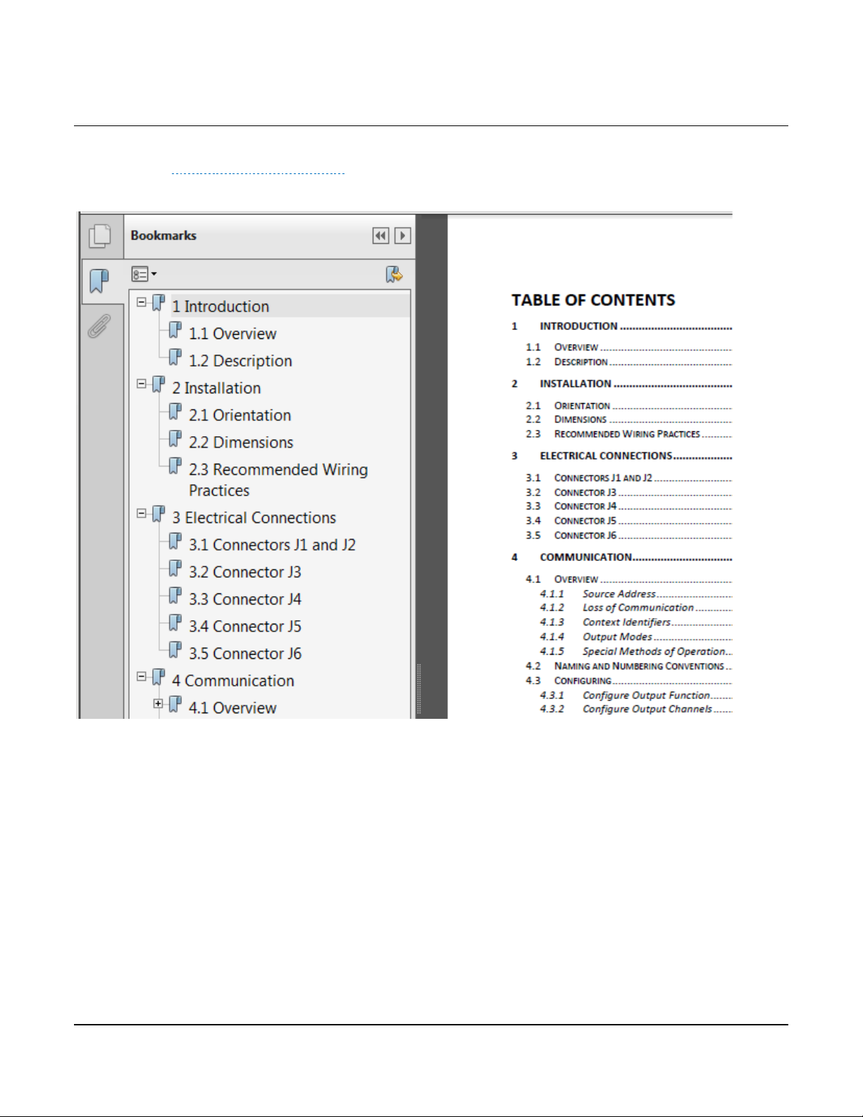
This document features Adobe Reader bookmarks to quickly jump between sections.
Additionally, blue-colored hyperlinks are used throughout the manual to allow easy navigation
between the various CAN messages.
Section 80 00-02-0829
2018-02-26 - 6 -
Page 9
2 Installation
2.1 Mounting Orientation
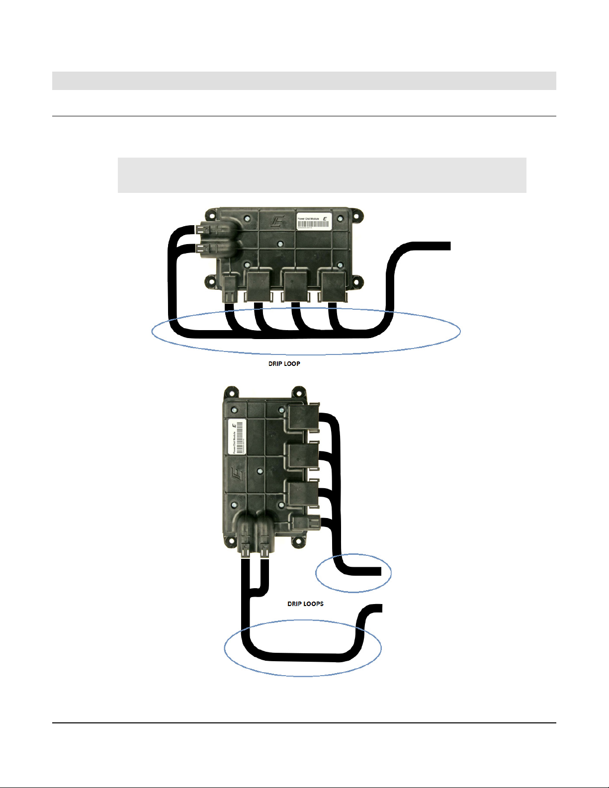
The PDM should be mounted on a vertical surface with either J3 – J6 facing down or to the
right. Secure the module with either 6 mm or 1/4 in. diameter fasteners.
IMPORTANT: The harness should have a drip loop(s) to allow water
to run off the wires.
IX3212 PDM shown in preferred mounting orientations
Section 80 00-02-0829
2018-02-26 - 7 -
Page 10
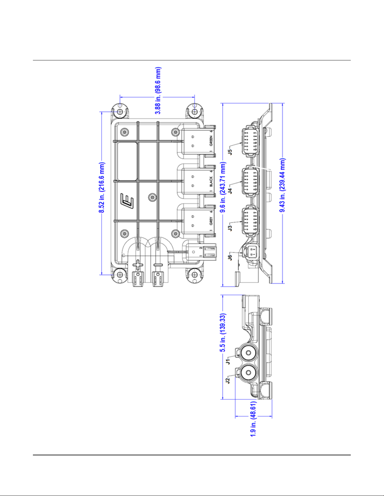
2.2 Dimensions
IX3212 PDM Dimensions
Section 80 00-02-0829
2018-02-26 - 8 -
Page 11
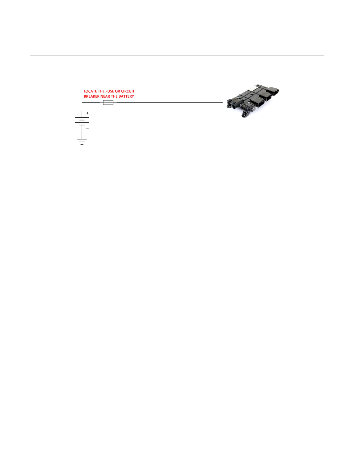
2.3 Circuit Protection
A fuse or circuit break on the positive power input (connector J2) is required and should be
located near the power source (e.g. battery).
The outputs are monitored for over-current conditions and turn-off in the event of the fault. For
information on how to configure the output current limit, refer to Section 4.3.2 – Configure
Output Channels.
2.4 Recommended Wiring Practices
This section contains information about the IX3212 connectors and pin outs. Please use the
following recommended wiring practices when installing and using the PDM:
• Ensure correct and adequate single point ground to prevent ground loops.
• Use twisted or twisted shielded pair cable for the CAN bus per the applicable standard.
• Ensure the appropriate sized conductor is specified for the intended load current in the
harness design for the particular application.
o SAE J1614 specifies requirements and design guidelines for electrical wiring
systems of less than 50 V and cable diameters from 0.35 mm2 to 19 mm2 used
on off-road, self-propelled earthmoving machines as defined in SAE J1116 and
agricultural tractors as defined in ASAE S390.
o SAE J2202 recommends and describes the application of the primary wiring
distribution system of less than 50 V and includes wire sizes 0.5 mm2 to 19 mm2
on heavy-duty on-highway trucks.
o SAE J1128, ISO 6722 and JASO D608-92 automotive wiring standards aid in
determining the recommended conductor sizing table for the respective 12V or
24V system that is powering the load.
o ABA specifies a marine wiring standard that differs from SAE J1128.
• Wire gauges should be capable of handling at least 135 percent of the circuit’s current
protection rating.
o Determine the maximum load the wire is expected to carry, the location of wiring
(e.g. in a cab or engine compartment) and ambient temperature).
o Determine the length of the wire needed to extend from the power source to the
load. Include the ground wire length if used.
Section 80 00-02-0829
2018-02-26 - 9 -
Page 12

o Insure that the voltage drop at the load is kept within the recommended
CABLE CONVERSION CHART – METRIC vs. ENGLISH
LOW-TENSION PRIMARY CABLE – SAE J1128
Metric
English
Metric
English
0.5 mm2
20 Ga
5.0 mm2
10 Ga
0.8 mm2
18 Ga
8.0 mm2
8 Ga
1.0 mm2
16 Ga
13.0 mm2
6 Ga
2.0 mm2
14 Ga
19.0 mm2
4 Ga
3.0 mm2
12 Ga
10 percent maximum level for the respective 12V or 24V power system.
• Wire gauge reductions are permissible after the point at which circuit protection is
added or enabled.
• Wires should be specified with suitable insulation type for the environment. For
instance, GXL (general purpose, cross-linked polyethylene insulated) wire with a
medium insulation thickness has a rating of +135°C (+275°F) where the compartment
temperatures can exceed +80°C (+176°F) such as the engine compartment.
NOTE: Review the individual over-current shutdown values in the
configuration and use the correct wire gauge conductor to accommodate
maximum load current configured.
• Use a protective fuse or circuit breaker on the positive input power lead (J2) that is
sized appropriately for the PDM supply steady-state load current. Typical maximum
load current is 60 percent - 80 percent of the fuse rating not to exceed 70 A.
• Verify that the harness is constructed to meet the needs of the application environment
(e.g. shock, vibration, moisture, temperature, chemicals and impact).
• Make certain that the harness is designed and constructed to minimize induced
interference resulting from EMI coupling between signal wires.
• Separate power circuits from low-level signals.
• Make provisions for drip loops to attach devices in exposed locations and prevent
moisture entry and formation within the connectors.
• Provide sufficient clearance from moving parts.
• Wires routed through holes in the vehicle body/chassis should use grommets.
• Avoid sharp metal edges, fasteners and other abrasive surfaces or use protective
shielding when routing harness assembly.
• Route wires to avoid exhaust system components or other high temperature areas. Use
appropriate heat shielding or other insulation where routing is a problem.
• Avoid routing near wheel wells or provide adequate mechanical protection (e.g.
convoluted conduit) to the wire assembly.
Section 80 00-02-0829
2018-02-26 - 10 -
Page 13
3 Electrical Connections
PIN
FUNCTION
LIMIT
Mating Connector
J1
Ground
70 A continuous (return)
DTHD 06-1-4S
J2
V
BATT
70 A continuous (source)
DTHD 06-1-4S
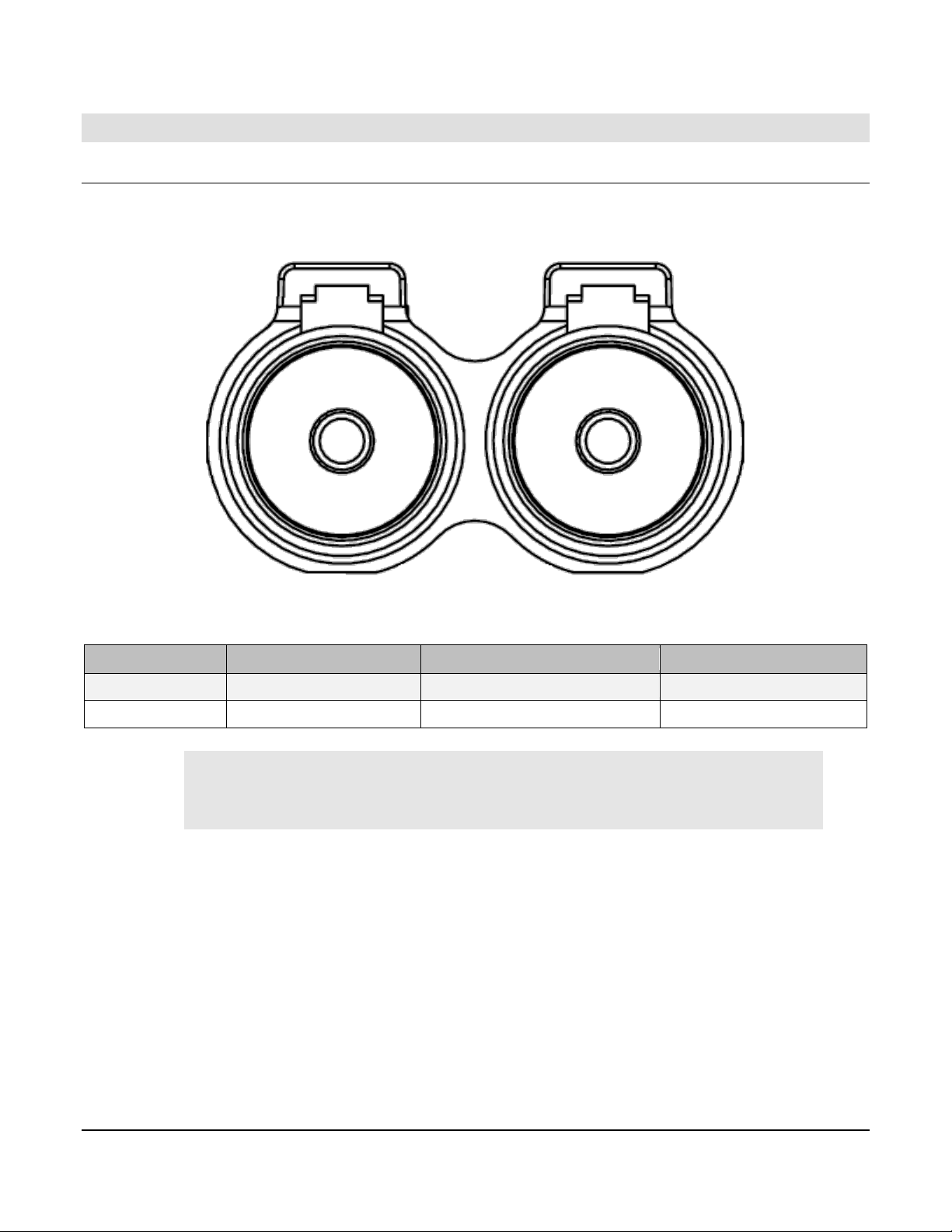
3.1 Connectors J1 and J2
The connector pinout is as viewed looking into the PDM receptacles or from the wire side of
the mating plugs.
J2 J1
+ −
IMPORTANT: A circuit breaker or fuse is required on the
connection leading to J2 and should be located near the battery or
power source.
Section 80 00-02-0829
2018-02-26 - 11 -
Page 14
Pin
Function
Limit
Mating Connector
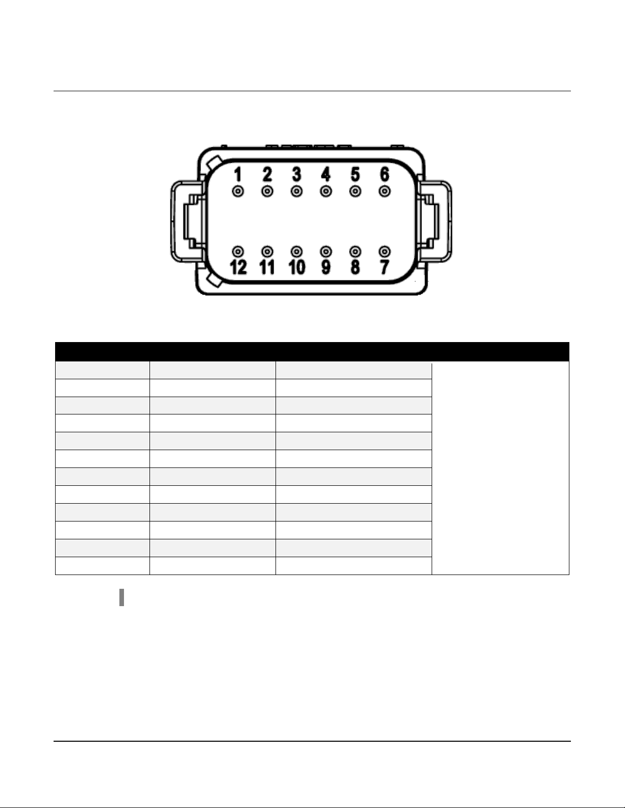
J3-1
5V Regulated Output
GND (Isolated)
5 V @ 70 mA (both pins)
J3-2
Digital Input 12
0-28 VDC
J3-3
Digital Output 7
15 A (PWM @ 100 Hz)
J3-4
Digital Output 8
15 A (PWM @ 100 Hz)
J3-5
Digital Output 9
15 A (PWM @ 100 Hz)
J3-6
Digital Output 10
15 A (PWM @ 100 Hz)
J3-7
Analog Input 8
0 – 5 V
J3-8
Analog Input 7
0 – 5 V
J3-9
Analog Input 6
0 – 5 V
J3-10
Analog Input 5
0 – 5 V
J3-11
Analog Input 4
0 – 5 V
J3-12
5V Regulated Output
(+)
5 V @ 70 mA (Both pins)
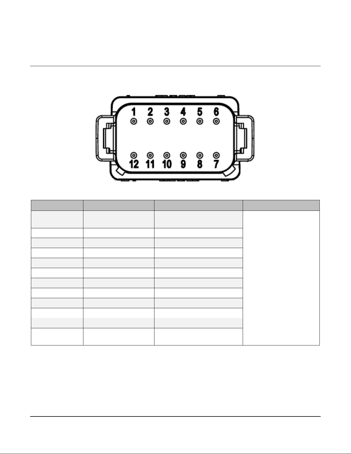
3.2 Connector J3
The connector pinout is as viewed looking into the PDM receptacles or from the wire side of
the mating plugs.
J3
DT06-12SA (Gray)
Section 80 00-02-0829
2018-02-26 - 12 -
Page 15
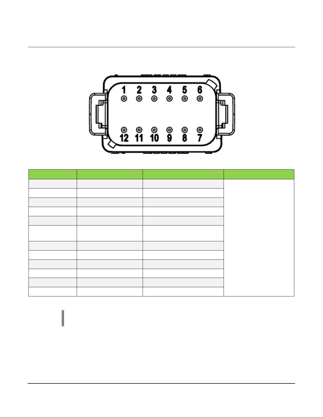
3.3 Connector J4
Pin
Function
Limit
Mating Connector
J4-1
Digital Output 1
15 A (PWM @ 500 Hz)
J4-2
Digital Output 2
15 A (PWM @ 500 Hz)
J4-3
Digital Output 3
15 A (PWM @ 500 Hz)
J4-4
Digital Output 4
15 A (PWM @ 500 Hz)
J4-5
Digital Output 5
15 A (PWM @ 500 Hz)
J4-6
Digital Output 6
15 A (PWM @ 500 Hz)
J4-7
Analog Input 3
0 – 5 V
J4-8
Analog Input 2
Resistive
J4-9
Analog Input 1
Resistive
J4-10
Digital Input 11
0 – 28 VDC
J4-11
Digital Input 2
0 – 28 VDC
J4-12
Digital Input 1
0 – 28 VDC
The connector pinout is as viewed looking into the PDM receptacles or from the wire side of
the mating plugs.
J4
DT06-12SB (Black)
NOTE: Digital Inputs 1 and 2 are used to set the Source Address.
Section 80 00-02-0829
2018-02-26 - 13 -
Page 16
3.4 Connector J5
PIN
FUNCTION
LIMIT
Mating Connector
J5-1
CAN LOW
-
J5-2
Digital Input 3
0 – 28 VDC
J5-3
Digital Input 4
0 – 28 VDC
J5-4
Digital Input 5
0 – 28 VDC
J5-5
Digital Input 6
0 – 28 VDC
J5-6
Regulated Output GND
(Isolated)
5 V @ 70 mA (both pins)
J5-7
Regulated Output (+)
5 V @ 70 mA (both pins)
J5-8
Digital Input 7
0 – 28 VDC
J5-9
Digital Input 8
0 – 28 VDC
J5-10
Digital Input 9
0 – 28 VDC
J5-11
Digital Input 10
0 – 28 VDC
J5-12
CAN HIGH
-
The connector pinout is as viewed looking into the PDM receptacles or from the wire side of
the mating plugs.
J5
DT06-12SC (Green)
NOTE: The CAN bus circuit has an auto-termination detection circuit builtin that is disabled by default.
Section 80 00-02-0829
2018-02-26 - 14 -
Page 17
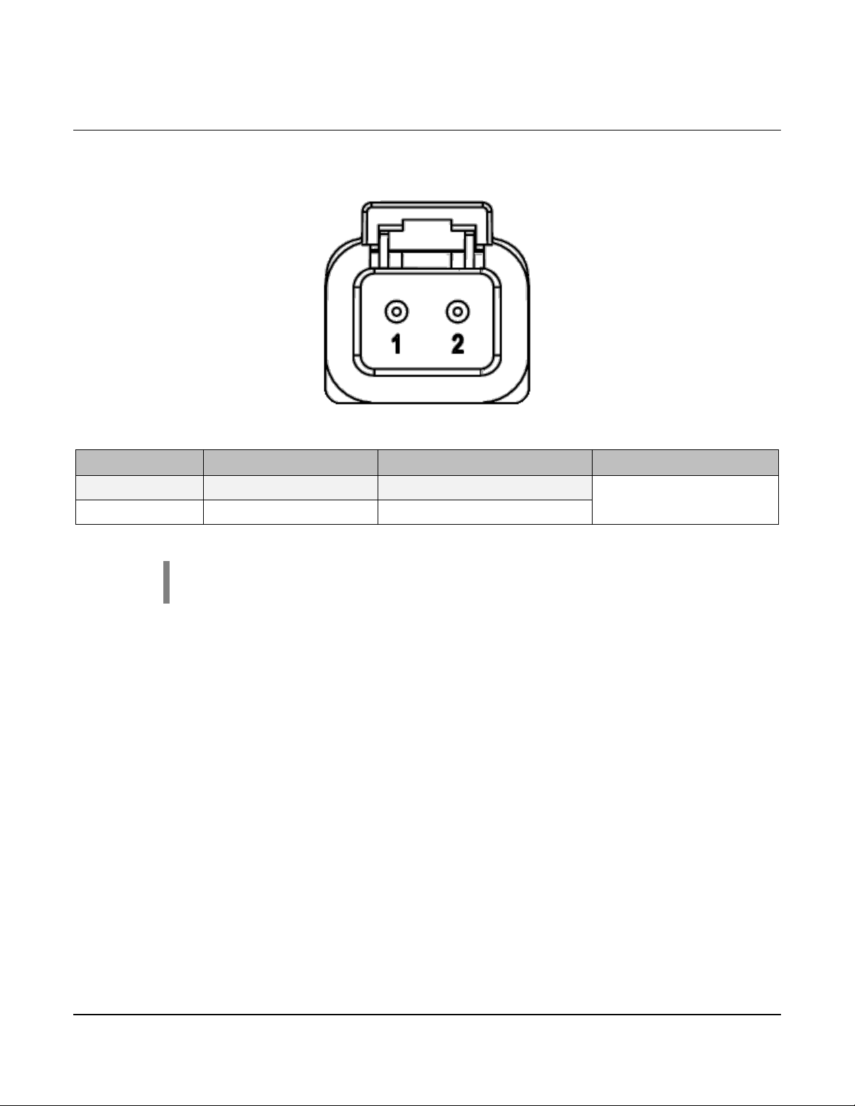
3.5 Connector J6
PIN
FUNCTION
LIMIT
Mating Connector
J6-1
Digital Output 12
15 A (PWM @ 100 Hz)
J6-2
Digital Output 11
15 A (PWM @ 100 Hz)
The connector pinout is as viewed looking into the PDM receptacles or from the wire side of
the mating plugs.
J6
DTP06-2S
NOTE: Deutsch DT series contacts are size 16. DTP series contacts are
size 12.
Section 80 00-02-0829
2018-02-26 - 15 -
Page 18

4 Communication
4.1 Overview
The IX3212 PDM uses proprietary SAE J1939 CAN messages to configure control, and
communicate the I/O status. PowerView displays or a compatible CAN 2.0B CAN bus device
can be used to send CAN messages.
Each CAN message has an identifier in the first byte that determines the message context.
There are five unique identifiers associated with command and configuration and nine unique
identifiers associated with input status, feedback, diagnostics and data reported by the PDM.
4.1.1 Source Address
The Source Address (SA) is set using the first two digital inputs. A 1/open indicates the input
is open circuit or at high potential (i.e., connected to battery positive DC). A 0 indicates the
input is connected to a low potential (i.e., ground). Inputs contain a pull-up resistor that
interprets the input as High if left unconnected. Table 1 lists the available source addresses
and allows for up to four PDM modules on a single CAN bus. The PDM defaults to SA 30
(17h) if the inputs are not connected. The PDM does not support SA arbitration according to
J1939.
Digital Input 1 Digital Input 2 SA
1/open 1/open
0 1/open 31 (1Fh)
1/open 0 32 (20h)
0 0 33 (21h)
Table 1 – Source Address Selection
IMPORTANT: When multiple PDMs are connected to the same CAN
bus, each PDM must have a unique SA.
The PDM sends messages to and expects to receive messages from SA 17 (11h) regardless
of the actual SA claimed by the configuring and controlling device(s). If a system has a cruise
control or steer axle controller, the SA may conflict with the PDM.
30 (1Eh) default
4.1.2 Loss of Communication
The PDM expects to receive commands from a controlling device every second. If a CAN
command message is not received, the PDM assumes that the CAN bus is faulted and goes
into a Loss of Communication mode. Each output can be individually configured to respond in
prescribed way and is further defined in the section on Loss of Communication.
Section 80 00-02-0829
2018-02-26 - 16 -
Page 19

4.1.3 Output Modes
Two slave modes of operation are possible where the PDM is configured and controlled by a
PowerView display or some other CAN bus controller.
1. High-Side Switch (HSS): This mode of operation is the typical standard output to turn a
load on or off. The individual outputs can switch up to 15 A loads. This mode also
supports PWM to drive a load proportionally (open-loop).
2. H-Bridge (HB): This mode allows two adjacent outputs to switch polarity of the voltage
applied to the load. This is often used to change direction of a DC motor and run it in
reverse. This mode supports PWM to drive a load proportionally.
4.1.4 Special Methods of Operation
The PDM is a flexible power I/O module and offers the following configurable features:
4.1.4.1 Power on Reset (POR)
This mechanism enables the PDM to retain an output state through power cycles of the unit.
The PDM can power up with individual outputs at predefined PWM levels.
4.1.4.2 Local Source Control
Local Source Control (LSC) is a mode that enables any digital input to trigger the
respective output. The effect of this mode is to allow any number of outputs to be
autonomously commanded by the specified input.
It is possible to use the PDM in stand-alone operation using LSC. Once the PDM has
been configured on the production line, the unit can operate autonomously.
An example use of this function is connecting a key switch to a digital input on the PDM
to power an output, which in turn energizes the remainder of the electronic modules that
are driven by the key switch.
Using this feature inhibits the other output modes of operation such as the PWM values
on the specific outputs configured for LSC mode.
IMPORTANT: Configuring LSC mode on an output disables the Loss
of Communication function for the respective output since there is
no way of knowing if CAN communication is expected or not.
Section 80 00-02-0829
2018-02-26 - 17 -
Page 20

4.2 Naming and Numbering Conventions
Example Message
Data Length
Start Position
Length
Parameter Name
Reference
1
1 byte
Feedback and Diagnostics Identifier
4.5.1.1
2.5
2 bits
Digital Input 3
4.5.1.2
2.3
2 bits
Digital Input 2
4.5.1.2
3.7
2 bits
Digital Input 8
4.5.1.2
3.5
2 bits
Digital Input 7
4.5.1.2
4.7
2 bits
Digital Input 12
4.5.1.2
4.5
2 bits
Digital Input 11
4.5.1.2
4.1
2 bits
Digital Input 9
4.5.1.2
5
2 bytes
Analog Input 1
4.5.1.3
The byte/bit order is represented in the following figure. Bit 1 is the least significant bit (lsb)
and Bit 8 is the most significant bit (msb). Byte 1 is the transmitted first and Byte 8 is last (i.e.
sequential).
The structures are defined for each type of configuration, control, feedback and diagnostic
message.
The following example message structure closely follows the SAE J1939 PGN convention.
The message must contain 8 bytes.
8 bytes
2.7 2 bits Digital Input 4 4.5.1.2
2.1 2 bits Digital Input 1 4.5.1.2
3.3 2 bits Digital Input 6 4.5.1.2
3.1 2 bits Digital Input 5 4.5.1.2
4.3 2 bits Digital Input 10 4.5.1.2
7 2 bytes Analog Input 2 4.5.1.3
Section 80 00-02-0829
2018-02-26 - 18 -
Page 21

Bit placement is sequential from the starting byte/bit position. For example, an analog input is
Byte 1
Byte 2
Byte 3
Byte 4
Bits
8 7 6 5 4 3 2 1 8 7 6 5 4 3 2 1 8 7 6 5 4 3 2 1 8 7 6 5 4 3 2
1
Data
1 1 0 1 1 1 0 1 1 1 1 1 1 1 0 0
expressed as a 10 bit value in 2 bytes of data. The start position is given as 2.2 meaning byte
2, bit 2. The 10 bits are ordered starting in byte 2, bit 2 and continue throughout byte 1. The
illustration below shows the numeric value 221 (DDh) or 00 1101 1101 in binary format in the
dark gray portion. The light gray bits are not used.
Example Start Position
NOTE: As specified by J1939, unused data bits are filled with 1 and report
back as 0.
Section 80 00-02-0829
2018-02-26 - 19 -
Page 22

4.3 Configuring
The IX3212 PDM is configured via the CAN bus messages for either slave or LSC
(autonomous) operation. In the slave configuration, where a PowerView display or a CAN bus
controller is controlling the PDM, it is recommended that the configuration messages be sent
on every power-up. It is also possible to re-configure the PDM on the fly.
The following two message types define how to configure the PDM:
• Configure Output
• Configure Output Channels
PowerVision Configuration Studio® 2.7 and later versions have a development application
which makes it easy to configure and control the Output Functions and Channels using
PowerView displays.
See the PowerVision Applications Reference Manual for further details on the use of the
application.
Section 80 00-02-0829
2018-02-26 - 20 -
Page 23

4.3.1 Configure Output Function
CAN message sent to the PDM to set up the configuration or command the outputs.
Transmission Repetition
On change of state
Data Length
8 bytes
Data Page
0
PDU Format (PF)
239
Proprietary A, PDU1 format
PDU Specific (PS)
Priority
5
Parameter Group Number
61184 (EF00h)
1
1 byte
Configuration or Command Identifier
4.3.1.1
2
1 byte
Output Channel Number
4.3.1.2
4
1 byte
Motor/Lamp Mode
4.3.1.4
5.3
6 bits
Reserved (Always high, binary 111111)
6
1 byte
Reserved (always FFh)
7.4
5 bits
POR Command
4.3.1.6
7.2
1 bit
Command Type
4.3.1.8
7.1
1 bit
Motor Braking
4.3.1.9
8.5
4 bits
LSC Digital Input
4.3.1.10
8.1
2 bits
Response
4.3.1.12
The Configure Output Function message sets the mode, power-on characteristics and general
behavior for each output. The message must be sent at least one time for LSC and as often
as required if the output configuration needs to change. A handshake message is returned by
the PDM to confirm the setup.
30 (1Eh) or as set DA (Source Address of the PDM)
Start Position Length Parameter Name Reference
3 1 byte Soft-Start Step Size 4.3.1.3
5.1 2 bits Loss of Communication 4.3.1.5
7.3 1 bit POR Enable 4.3.1.7
8.3 2 bits Calibration Time 4.3.1.11
Section 80 00-02-0829
2018-02-26 - 21 -
Page 24

4.3.1.1 Configuration Identifier
This identifier is a secondary address that indicates the type of message, in this case output functionality.
0 Output Configuration
Data Length:
1 byte
Resolution:
5 states / 1 byte
0 offset
Data Range:
0
Operational Range:
same as data range
PGN:
PGN 61184 – Configure Output
This specifies which output channel, 1-12, is configured by the message.
1 = Channel 1, 2 = Channel 2, 3 = Channel 3, etc.
Data Length:
1 byte
Resolution:
8 states / 1 byte
0 offset
Data Range:
Type:
Status (command)
PGN:
PGN 61184 – Configure Output
Motors and lamps often require soft-starting to reduce the in-rush current and prevent the PDM from producing
255 (FFh) = 100% (Soft-Start disabled)
Data Length:
Resolution:
1% / 1 bit
0 offset
Data Range:
1 to 100
Operational Range:
same as data range
Type:
Type:
Status (command)
4.3.1.2 Output Channel
1 to 12 Operational Range: same as data range
4.3.1.3 Soft-Start Step Size
over-current errors. Also lights can be soft-started to reduce the in-rush current and potentially extend the
filament life.
1 = 1%, 2 = 2%, 3 = 3%, etc.
1 byte
Status (command)
PGN:
PGN 61184 – Configure Output
Soft-start step size is a PWM value representing a percentage in which the output is increased
in steps. Depending on the mode (i.e. lamp or motor) selected, the time between each step
varies. The first step lasts 500 ms in either mode. The subsequent steps are only 20 ms in
lamp mode. Alternately, the motor mode remains at 500 ms step intervals. Lower percentage
soft-start values therefore equate to longer soft-start times.
Section 80 00-02-0829
2018-02-26 - 22 -
Page 25

For example, a soft-start value of 10% using lamp mode means that the PDM reaches 100%
after 680 ms. Whereas the same 10% value using motor mode takes 5,000 ms to reach
100%. The illustrations below show the time base of an example 10% PWM value.
Command (Lamp Mode)
100
90
80
70
60
50
40
30
PWM Value (%)
20
10
0
0
100
200
Elapsed Time (ms)
300
400
500
600
700
Command (Motor Mode)
100
90
80
70
60
50
40
30
PWM Value (%)
20
10
0
0
1000
Elapsed Time (ms)
2000
3000
4000
5000
Depending on the Command (final) value and the soft-start step size, the elapsed time to
reach the final PWM value may vary by one or two steps.
Section 80 00-02-0829
2018-02-26 - 23 -
Page 26

4.3.1.4 Motor/Lamp Mode
The over-current profile can be selected depending on the type of load. See the current profile in the figures
1 Motor
Data Length:
1 byte
Resolution:
Data Range:
0 to 1
Operational Range:
same as data range
Type:
Status (command)
PGN:
below.
0 Lamp
2 states / 1 byte 0 offset
PGN 61184 – Configure Output
Lamp filaments exhibit a high peak inrush current when first powered. A stair-shaped profile
for the overcurrent protection is preprogrammed at the factory.
The lamp mode peak current is limited to 110 A nominally for 17.2 ms. The next level is 43.3 A
for 137 ms. Finally, up to 15 A of continuous current is the maximum limit. If the limit is
exceeded anywhere along the profile including a lower continuous current limit that may be
set, the FET goes into protection mode.
Section 80 00-02-0829
2018-02-26 - 24 -
Page 27

DC motors or inductive loads such as relays exhibit a delayed inrush or stall current. A
Defines how the outputs behave when CAN communication is lost. This can be useful in many applications, but
11 = CH 0% (off)
Data Length:
2 bits
Resolution:
Data Range:
0 to 3
Operational Range:
same as data range
Type:
Status (command)
PGN:
window-shaped profile for the overcurrent and overheating protection is pre-programmed at
the factory.
The motor mode peak current is limited to 43.3 A nominally for up to 429 ms. The final level is
set at up to 15 A continuous current. If the limit is exceeded anywhere along the profile
including a lower continuous current limit that may be set, the FET goes into protection mode.
The Soft-Start function can be used in combination with the motor/lamp mode to affect the
inrush current and prevent an over-current condition.
NOTE: The inductance of the motor, inertia of the rotor and load,
including a stalled rotor condition factor into whether the PDM is capable
of driving a DC motor. Experimentation is often necessary to determine if
a DC motor is compatible with the PDM.
4.3.1.5 Loss of Communication
because the PDM is no longer under supervisory control, appropriate testing should be conducted to ensure safe
operation.
00 = CH Unchanged (Last Commanded)
01 = CH -100% (H-Bridge Only)
10 = CH +100%
4 states / 2 bits 0 offset
PGN 61184 – Configure Output
Section 80 00-02-0829
2018-02-26 - 25 -
Page 28

The POR Command sets the percentage PWM level for each output at module power on/reset. This establishes
Data Length:
Resolution:
6.25 % / lsb
-100 % offset
Data Range:
-100 % to 100 %
Operational Range:
same as data range
Type:
POR Command Value
Commanded PWM %
Actual PWM %
01111
93.75
100
01100
75
75
01011
68.75
68.75
01010
62.5
62.5
00111
43.75
43.75
00110
37.5
37.5
00101
31.25
31.25
00010
12.5
12.5
00001
6.25
6.25
00000
0
0
11101
-18.75
-18.75
11100
-25
-25
11011
-31.25
-31.25
4.3.1.6 POR Command
the output PWM level an individual output will be commanded to at start up. This can be useful in many
applications, but because the PDM is no longer under supervisory control, appropriate testing should be
conducted to ensure safe operation.
5 bits, signed
Status (command)
PGN:
PGN 61184 – Configure Output
01110 87.5 87.5
01101 81.25 81.25
01001 56.25 56.25
01000 50 50
00100 25 25
00011 18.75 18.75
11111 -6.25 -6.25
11110 -12.5 -12.5
Section 80 00-02-0829
2018-02-26 - 26 -
Page 29

POR Command Value
Commanded PWM %
Actual PWM %
11010
-37.5
-37.5
11001 -43.75 -43.75
10111
-56.25
-56.25
10110
-62.5
-62.5
10101
-68.75
-68.75
10010
-87.5
-87.5
10001
-93.75
-93.75
10000
-100
-100
POR enables the above power on reset functionality for the individual output.
0 Enabled
Data Length:
Resolution:
2 states / 1 bit
0 offset
Data Range:
0 to 1
Operational Range:
same as data range
Type:
Command type determines if the loss of CAN feature is enabled or disabled.
1 Disabled
Data Length:
1 bit
Resolution:
Data Range:
0 to 1
Operational Range:
same as data range
Type:
Status (command)
PGN:
11000 -50 -50
10100 -75 -75
10011 -81.25 -81.25
4.3.1.7 POR Enable
1 Disabled
1 bit
Status (command)
PGN:
PGN 61184 – Configure Output
4.3.1.8 Command Type
0 Enabled
2 states / 1 bit 0 offset
PGN 61184 – Configure Output
Section 80 00-02-0829
2018-02-26 - 27 -
Page 30

4.3.1.9 Motor Braking
Motor braking for H-bridge controlled outputs. This enables motor braking for the specific H-Bridge pair.
1 Enabled
Data Length:
1 bit
Resolution:
Data Range:
0 to 1
Operational Range:
same as data range
Type:
Status (command)
PGN:
Specifies the Digital Input number that is associated with the output channel for the LSC mode.
0xFF.
Data Length:
4 bits
Resolution:
Type:
Status (command)
PGN:
PGN 61184 – Configure Output
Calibration time. This feature is not currently supported.
NOTE: Since this feature is unsupported, these two bits must always be 11.
Data Length:
Data Range:
0 to 1
Operational Range:
same as data range
Type:
Status (command)
0 Disabled
2 states / 1 bit 0 offset
PGN 61184 – Configure Output
4.3.1.10 LSC Digital Input
0 Channel 1
1 Channel 2
2 Channel 3
..
11 Channel 12
15 (0xF) LSC disabled (default)
NOTE: When not using LSC, all 4 bits must be 1111 (0x15). The two bytes associated
with calibration time below, since it is unsupported, must be 11. The two bits associated
with Response below must also be 11. Therefore, when not using LSC, Byte 8 must be
12 states / 4 bits 0 offset
Data Range:
0 to 11 Operational Range: same as data range
4.3.1.11 Calibration Time
0 Override Fixed (always 0 for H-bridge)
1 Override Calibration Time
2 bits
Resolution:
PGN:
2 states / 2 bits 0 offset
PGN 61184 – Configure Output
Section 80 00-02-0829
2018-02-26 - 28 -
Page 31

4.3.1.12 Response
Response indicates how the output channel turns-on depending on the input is active low, high or both (either
11 Active Low or High
Data Length:
2 bits
Resolution:
Data Range:
0 to 1
Operational Range:
same as data range
Type:
Status (command)
PGN:
low or high).
00 Reserved
01 Active Low
10 Active High
2 states / 2 bits 0 offset
PGN 61184 – Configure Output
Section 80 00-02-0829
2018-02-26 - 29 -
Page 32

4.3.2 Configure Output Channels
Configure Output Channels is a message sent to the PDM to set up the high-current output channels as a single
Transmission Repetition
On change of state (at least one time, < 1 sec)
Data Length
PDU Format (PF)
239
Proprietary A, PDU1 format
PDU Specific (PS)
30 (1Eh) or as set
DA (Source Address of the PDM)
Priority
Parameter Group Number
61184 (EF00h)
Start Position
Length
Parameter Name
Reference
2.5
4 bits
Current Limit (Output Channel 1 or 7)
4.3.2.2
2.3
2 bits
Feedback Type (Output Channel 1 or 7)
4.3.2.3
2.1
1 bit
High-Side or H-Bridge (Output Channel 1 or 7)
4.3.2.5
3.5
4 bits
Current Limit (Output Channel 2 or 8)
4.3.2.2
3.2
1 bit
Automatic Reset (Output Channel 2 or 8)
4.3.2.3
3.1
1 bit
High-Side or H-Bridge (Output Channel 2 or 8)
4.3.2.5
4.2
1 bit
Automatic Reset (Output Channel 3 or 9)
4.3.2.3
4.1
1 bit
High-Side or H-Bridge (Output Channel 3 or 9)
4.3.2.5
5.3
2 bits
Feedback Type (Output Channel 4 or 10)
4.3.2.3
5.2
1 bit
Automatic Reset (Output Channel 4 or 10)
4.3.2.3
The following CAN message also configures the outputs in two groups.
high-side output or as an H-bridge pair. It also sets the current limit and reset behavior. Depending on the
output configuration identifier, the message applies to either output channels 1-6 or 7-12 respectively.
Note: When channels are set to H-bridge pair, they are paired
consecutively (i.e. 1 and 2, 3 and 4, etc.).
8 bytes
Data Page
1 1 byte Output Channel Group Identifier 4.3.2.1
2.2 1 bit Automatic Reset (Output Channel 1 or 7) 4.3.2.3
3.3 2 bits Feedback Type (Output Channel 2 or 8) 4.3.2.3
0
5
4.5 4 bits Current Limit (Output Channel 3 or 9) 4.3.2.2
4.3 2 bits Feedback Type (Output Channel 3 or 9) 4.3.2.3
5.5 4 bits Current Limit (Output Channel 4 or 10) 4.3.2.2
5.1 1 bit High-Side or H-Bridge (Output Channel 4 or 10) 4.3.2.5
Section 80 00-02-0829
2018-02-26 - 30 -
Page 33

6.5
4 bits
Current Limit (Output Channel 5 or 11)
4.3.2.2
6.3 2 bits Feedback Type (Output Channel 5 or 11) 4.3.2.3
6.2
1 bit
Automatic Reset (Output Channel 5 or 11)
4.3.2.3
6.1
1 bit
High-Side or H-Bridge (Output Channel 5 or 11)
4.3.2.5
7.2
1 bit
Automatic Reset (Output Channel 6 or 12)
4.3.2.3
7.1
1 bit
High-Side or H-Bridge (Output Channel 6 or 12)
4.3.2.5
This identifier is a secondary address that determines which set of outputs will be configured.
7 Output Channels 7-12
Resolution:
2 states / 1 byte
0 offset
Data Range:
0
Operational Range:
same as data range
Type:
PGN:
PGN 61184 – Configure Output Channels
Current Limit sets the steady-state, over-current shutdown level in 2.5A increments.
7-15 Reserved
Data Length:
4 bits
Resolution:
7 states / 4 bits
0 offset
Type:
Status (command)
PGN:
PGN 61184 – Configure Output Channels
7.5 4 bits Current Limit (Output Channel 6 or 12) 4.3.2.2
7.3 2 bits Feedback Type (Output Channel 6 or 12) 4.3.2.3
8 1 byte Reserved (FFh)
4.3.2.1 Output Channel Group Identifier
6 Output Channels 1-6
Data Length:
1 byte
Status (command)
4.3.2.2 Current Limit
0 – 0.0 A
1 – 2.5 A
2 – 5.0 A
3 – 7.5 A
4 – 10.0 A
5 – 12.5 A
6 – 15.0 A
Data Range:
0 – 15 A Operational Range: same as data range
Section 80 00-02-0829
2018-02-26 - 31 -
Page 34

4.3.2.3 Feedback Type
Feedback type is always set to Current. The other modes are not supported on the IX3212-24.
11 Current feedback (always)
Data Length:
2 bits
Resolution:
4 states / 2 bits
0 offset
Data Range:
3
Operational Range:
same as data range
Type:
Status (measured)
PGN:
PGN 61184 – Configure Output Channels or Output Configuration Handshake
Automatic Reset specifies if the PDM shall autonomously reset the output or remain in the OFF state during an
1 No automatic reset (remain in OFF state)
Data Length:
1 bit
Resolution:
Type:
Status (command)
PGN:
PGN 61184 – Configure Output Channels or Output Configuration Handshake
00 Position feedback (not supported on the IX3212-24)
01 Rate feedback (not supported on the IX3212-24)
10 Power feedback (not supported on the IX3212-24)
4.3.2.4 Automatic Reset
over-current event. Once an output is turned OFF by the PDM, the output needs to be commanded OFF prior to
commanding the output.
0 Automatic reset (5 attempts to reset before remaining OFF)
Data Range:
states / 1 byte 0 offset
0 Operational Range: same as data range
Section 80 00-02-0829
2018-02-26 - 32 -
Page 35

4.3.2.5 High-Side or H-Bridge
High-side or H-Bridge configures either a single output for driving discrete loads or assigns a pair of outputs for
1 H-Bridge (dual)
Data Length:
1 bit
Resolution:
Data Range:
0
Operational Range:
same as data range
Type:
Status (command)
PGN:
directional motor control. H-Bridge pairs are grouped as follows: 1 and 2, 3 and 4, 5 and 6, etc.
Note: When configuring the output for H-bridge operation, the second
channel in the pair (even number) must have byte 2 set to 255.
0 High-Side (single)
2 states / 1 bit 0 offset
PGN 61184 – Configure Output Channels
Section 80 00-02-0829
2018-02-26 - 33 -
Page 36

4.4 Commanding
After the configuration is complete, the IX3212 outputs can be commanded. The following
message type defines how to command the PDM:
• Command Output Channels
Section 80 00-02-0829
2018-02-26 - 34 -
Page 37

4.4.1 Command Output Channels
CAN message sent to the PDM to drive the outputs.
Transmission Repetition
20 – 500 ms
Data Length
8 bytes
Data Page
PDU Specific (PS)
30 (1Eh) or as set
DA (Source Address of the PDM)
Priority
5
Parameter Group Number
Start Position
Length
Parameter Name
Reference
3
1 byte
Command (Output Channel 2 or 8)
4.4.1.2
4
1 byte
Command (Output Channel 3 or 9)
4.4.1.2
6
1 byte
Command (Output Channel 5 or 11)
4.4.1.2
7
1 byte
Command (Output Channel 6 or 12)
4.4.1.2
8.2
1 bit
Enable (Output Channel 2 or 8)
4.4.1.3
8.3
1 bit
Enable (Output Channel 3 or 9)
4.4.1.3
8.6
1 bit
Enable (Output Channel 6 or 12)
4.4.1.3
8.7
2 bits
Module Transmit Rate / Unused
4.4.1.4
The command output channels message sets the PWM value of each output channel. The
message bytes refer to outputs 1-6 or 7-12, depending on the value of the identifier in the first
byte.
NOTE: A Command message must be broadcast to the PDM at least
once every second. Otherwise the PDM enters the Loss of
Communication state.
0
PDU Format (PF)
1 1 byte Output Command Identifier 4.4.1.1
2 1 byte Command (Output Channel 1 or 7) 4.4.1.2
5 1 byte Command (Output Channel 4 or 10) 4.4.1.2
8.1 1 bit Enable (Output Channel 1 or 7) 4.4.1.3
239 Proprietary A, PDU1 format
61184 (EF00h)
8.4 1 bit Enable (Output Channel 4 or 10) 4.4.1.3
8.5 1 bit Enable (Output Channel 5 or 11) 4.4.1.3
Section 80 00-02-0829
2018-02-26 - 35 -
Page 38

4.4.1.1 Output Command Identifier
This value defines which output channels the Command Output Channels message is referencing.
5 Output Channels 7-12
Data Length:
1 byte
Resolution:
2 states / 1 byte
0 offset
Data Range:
PGN:
PGN 61184 – Command Output Channels
This value defines the output channel’s PWM value as a percentage.
255 -0.78125%
Data Length:
1 byte
Resolution:
Data Range:
Type:
Status (command)
PGN:
PGN 61184 – Command Output Channels
4 Output Channels 1-6
4 or 5 Operational Range: same as data range
Type:
Status (command)
4.4.1.2 Command
This is a signed value (msb is the sign bit).
Note: When an output is either disabled or the second channel in an
H-bridge pair, the command should be set to 0 for that channel.
0 0%
1 +0.78125%
…
127 +100%
128 -100%
…
0.78125 % / lsb 0 offset
-100% to +100% Operational Range: same as data range
IMPORTANT: It may be necessary to turn on the outputs in a
staggered manner when multiple high-currents loads need to be
energized due to the high inrush current.
Section 80 00-02-0829
2018-02-26 - 36 -
Page 39

4.4.1.3 Enable
This value defines whether the specified channel is enabled or disabled.
1 Enabled
Data Length:
Resolution:
2 states / 1 bit
0 offset
Data Range:
0 or 1
Operational Range:
same as data range
Type:
This value defines the repetition rate that the PDM will transmit the feedback and diagnostics.
03 10ms
Data Length:
2 bits
Resolution:
4 states / 2 bits
0 offset
Data Range:
PGN:
PGN 61184 – Command Output Channels
NOTE: When a channel is disabled, it must have byte 2 set to 255 (FFh).
0 Disabled
1 bit
Status (command)
PGN:
PGN 61184 – Command Output Channels
4.4.1.4 Module Transmit Rate
00 500ms
01 250ms
02 50ms
0 to 3 Operational Range: same as data range
Type:
Status (command)
Section 80 00-02-0829
2018-02-26 - 37 -
Page 40

4.5 Feedback and Diagnostics
The IX3212 PDM will periodically transmit feedback messages with the measured analog
values and handshake.
The following message type defines how to command the PDM:
• Analog Inputs 1-2, Digital Inputs Feedback
• Analog Inputs 3-4, Output Diagnostics
• Analog Inputs 5-6, Battery and Sensor Supply
• Analog Inputs 7-8, Software Version and Power Supply
• Output Feedback
• Output Function Handshake
• Output Configuration Handshake
Section 80 00-02-0829
2018-02-26 - 38 -
Page 41

4.5.1 Analog Inputs 1-2, Digital Inputs Feedback
Transmission Repetition
50 ms minimum (5x the base rate)
Data Length
PDU Format (PF)
239
Proprietary A, PDU1 format
DA (Source Address of the configuring display or
controller)
Priority
5
Parameter Group Number
Start Position
Length
Parameter Name
Reference
1
1 byte
Feedback and Diagnostics Identifier
4.5.1.1
2.5
2 bits
Digital Input 3
4.5.1.2
2.3
2 bits
Digital Input 2
4.5.1.2
3.5
2 bits
Digital Input 7
4.5.1.2
3.3
2 bits
Digital Input 6
4.5.1.2
4.7
2 bits
Digital Input 12
4.5.1.2
4.5
2 bits
Digital Input 11
4.5.1.2
4.1
2 bits
Digital Input 9
4.5.1.2
5
2 bytes
Analog Input 1
4.5.1.3
The analog channel feedback is the value of the input signal on the respective channel with 10
bit resolution. The digital input indicates if the input is open (floating), connected to ground or
the battery.
CAN message sent by the PDM to communicate the measured values.
8 bytes
Data Page
PDU Specific (PS)
2.7 2 bits Digital Input 4 4.5.1.2
2.1 2 bits Digital Input 1 4.5.1.2
3.7 2 bits Digital Input 8 4.5.1.2
3.1 2 bits Digital Input 5 4.5.1.2
0
17 (11h)
61184 (EF00h)
4.3 2 bits Digital Input 10 4.5.1.2
7 2 bytes Analog Input 2 4.5.1.3
Regardless of the Source Address of the configuring and controlling device, that device must
listen for feedback messages addressed to Source Address 17 (11h).
Section 80 00-02-0829
2018-02-26 - 39 -
Page 42

4.5.1.1 Feedback and Diagnostics Identifier
All feedback and diagnostic messages contain a unique identifier which determines the associated information.
136 (88h) Output Configuration Handshake Channels 7-12
Data Length:
1 byte
Resolution:
Data Range:
0
Operational Range:
same as data range
Type:
Status (command)
PGN:
Three states describe each digital input.
Data Length:
2 bits
Resolution:
Type:
Status (measured)
PGN:
PGN 61184 – Feedback and Diagnostics
128 (80h) Analog Inputs 1-2, Digital Inputs
129 (81h) Analog Inputs 3-4, Output Diagnostics
130 (82h) Analog Inputs 5-6, Battery and Sensor Supply
131 (83h) Analog Inputs 7-8, Miscellaneous Feedback
132 (84h) Outputs 1-6 Feedback
133 (85h) Outputs 7-12 Feedback
134 (86h) Motor Model Handshake
135 (87h) Output Configuration Handshake Channels 1-6
1 state / 1 byte 0 offset
PGN 61184 – Feedback and Diagnostics
4.5.1.2 Digital Inputs
00 Open Circuit
01 Short-to-ground
10 Short-to-battery
11 Not Available
3 states / 2 bits 0 offset
Data Range:
- Operational Range: same as data range
Section 80 00-02-0829
2018-02-26 - 40 -
Page 43

Each analog input is represented by a 10-bit raw value for the 0-5V range by using two bytes.
MSB (2 bits)
Data Length:
2 bytes
Resolution:
Data Range:
Type:
Status (command)
PGN:
PGN 61184 – Feedback and Diagnostics
4.5.1.3 Analog Inputs
LSB (8 bits)
10 bits 0 offset
0-1023 Operational Range: same as data range
Example: If we consider the 10 bits of Analog Input 1 where 9 is the most significant bit and 0
is the least significant bit with n representing the unused bits, the bytes are ordered as follows:
LSB (byte 5): 76543210
MSB (byte 6): nnnnnn98
See the Condensed Message Definition at the end of the manual for a representation of all
analog inputs.
Section 80 00-02-0829
2018-02-26 - 41 -
Page 44

4.5.2 Analog Inputs 3-4, Output Diagnostics
CAN message sent by the PDM to communicate the measured values of Analog Inputs 3 and 4 as well as the
Output diagnostics.
Transmission Repetition
Data Length
8 bytes
Data Page
0
PDU Format (PF)
DA (Source Address of the configuring display or
controller)
Priority
Parameter Group Number
61184 (EF00h) - Feedback and Diagnostics
Start Position
Length
Parameter Name
Reference
2.7
2 bits
Output 1 Diagnostic
4.5.2.1
2.5
2 bits
Output 2 Diagnostic
4.5.2.1
2.1
2 bits
Output 4 Diagnostic
4.5.2.1
3.7
2 bits
Output 5 Diagnostic
4.5.2.1
3.3
2 bits
Output 7 Diagnostic
4.5.2.1
3.1
2 bits
Output 8 Diagnostic
4.5.2.1
4.7
2 bits
Output 9 Diagnostic
4.5.2.1
4.3
2 bits
Output 11 Diagnostic
4.5.2.1
4.1
2 bits
Output 12 Diagnostic
4.5.2.1
7
2 bytes
Analog Input 4
4.5.1.3
The analog channel feedback is the value of the associated analog inputs. The analog input is
represented by a 10 bit raw value for the 0-5 V range. The output diagnostics indicate: no
fault, a short-circuit, an over-current condition or an open-circuit.
20 – 500 ms
239 Proprietary A, PDU1 format
PDU Specific (PS)
1 1 byte Feedback and Diagnostics Identifier 4.5.1.1
2.3 2 bits Output 3 Diagnostic 4.5.2.1
3.5 2 bits Output 6 Diagnostic 4.5.2.1
4.5 2 bits Output 10 Diagnostic 4.5.2.1
17 (11h)
5
5 2 bytes Analog Input 3 4.5.1.3
Section 80 00-02-0829
2018-02-26 - 42 -
Page 45

4.5.2.1 Output Diagnostic
Output channel diagnostic status.
11 Open-circuit
Data Length:
2 bits
Resolution:
4 states / 2 bits
0 offset
Data Range:
PGN:
PGN 61184 – Feedback and Diagnostics
00 No faults
01 Short-circuit
10 Over-current
0-3 Operational Range: same as data range
Type:
Status (measured)
Section 80 00-02-0829
2018-02-26 - 43 -
Page 46

4.5.3 Analog Inputs 5-6, Battery and Sensor Supply
Transmission Repetition
20 – 500 ms
Data Length
PDU Format (PF)
239
Proprietary A, PDU1 format
DA (Source Address of the configuring display or
controller)
Priority
5
Parameter Group Number
Start Position
Length
Parameter Name
Reference
1
1 byte
Feedback and Diagnostics Identifier
4.5.1.1
4.5.3.2
below
3
2 bytes
Battery Voltage
4.5.3.3
5
2 bytes
Analog Input 5
4.5.1.3
The analog channel feedback is as follows: The analog input is represented by a 10 bit raw
value for the 0-5 V range. The Sensor supply bits indicate the supply is OK when the bit is
high (1). The battery voltage indicates the measured voltage 16 bits reflecting 0-63.99 Volts.
CAN message sent by the PDM to communicate the measured values.
8 bytes
Data Page
PDU Specific (PS)
2.1 1 bit Sensor Supply Low 4.5.3.1
2.2 1 bit Sensor Supply High
2.3-8 6 bits Reserved (always 3Fh (63)
7 2 bytes Analog Input 6 4.5.1.3
0
17 (11h)
61184 (EF00h) - Feedback and Diagnostics
Section 80 00-02-0829
2018-02-26 - 44 -
Page 47

4.5.3.1 Sensor Supply Low
5V sensor supply is out of range low.
1 5V output OK
Data Length:
1 bit
Resolution:
1
0 offset
Data Range:
PGN:
PGN 61184 – Feedback and Diagnostics
5V sensor supply is out of range high.
1 5V output OK
Data Length:
1 bit
Resolution:
Type:
Status
PGN:
PGN 61184 – Feedback and Diagnostics
The measured value of the battery voltage.
Data Length:
Data Range:
0-63.999 V
Operational Range:
same as data range
Type:
Status (measured)
PGN:
0 5V output too low
0-1 Operational Range: same as data range
Type:
Status
4.5.3.2 Sensor Supply High
0 5V output too high
1 0 offset
Data Range:
0-1 Operational Range: same as data range
4.5.3.3 Battery Voltage
2 bytes
Resolution:
10 bits 0 offset
PGN 61184 – Feedback and Diagnostics
Section 80 00-02-0829
2018-02-26 - 45 -
Page 48

4.5.4 Analog Inputs 7-8, Software Version and Power Supply
CAN message sent by the PDM to communicate the measured values.
Transmission Repetition
Data Length
8 bytes
Data Page
0
PDU Format (PF)
DA (Source Address of the configuring display or
controller)
Priority
Parameter Group Number
61184 (EF00h) - Feedback and Diagnostics
Start Position
Length
Parameter Name
Reference
2.1
1 bit
Total Current Status
4.5.4.1
2.2
1 bit
Power Supply Status
4.5.4.2
5
2 bytes
Analog Input 7
4.5.1.3
7
2 bytes
Analog Input 8
4.5.1.3
20 – 500 ms
239 Proprietary A, PDU1 format
PDU Specific (PS)
1 1 byte Feedback and Diagnostics Identifier 4.5.1.1
3 2 bytes Software Version 4.5.4.3
17 (11h)
5
Section 80 00-02-0829
2018-02-26 - 46 -
Page 49

4.5.4.1 Total Current Status
Total current status.
1 Total current OK
Data Length:
1 bit
Resolution:
1
0 offset
Data Range:
PGN:
PGN 61184 – Feedback and Diagnostics
Power supply status.
1 Power supply OK
Data Length:
1 bit
Resolution:
Type:
Status
PGN:
PGN 61184 – Feedback and Diagnostics
Data Length:
2 bytes
Resolution:
-
0 offset
Data Range:
Type:
Status (measured)
PGN:
PGN 61184 – Feedback and Diagnostics
0 Total current too high
0-1 Operational Range: same as data range
Type:
Status
4.5.4.2 Power Supply Status
0 Power supply NOT OK
1 0 offset
Data Range:
0-1 Operational Range: same as data range
4.5.4.3 Software Version
The software version number is represented by a 16 bit value.
- Operational Range: same as data range
Section 80 00-02-0829
2018-02-26 - 47 -
Page 50

4.5.5 Output Feedback
Transmission Repetition
20 – 500 ms
Data Length
8 bytes
Data Page
PDU Format (PF)
239
Proprietary A, PDU1 format
DA (Source Address of the configuring display or
controller)
Priority
5
Parameter Group Number
61184 (EF00h) - Feedback and Diagnostics
1
1 byte
Feedback and Diagnostics Identifier (132 or 133)
4.5.1.1
2
1 byte
Output 1 or 7 Feedback
4.5.5.1
4
1 byte
Output 3 or 9 Feedback
4.5.5.1
5
1 byte
Output 4 or 10 Feedback
4.5.5.1
7
1 byte
Output 6 or 12 Feedback
4.5.5.1
8
1 byte
Unused (always FFh)
WARNING: Closed-loop proportional control is not recommended due to the nondeterministic nature of the CAN bus.
CAN message sent by the PDM to communicate the measured values of the digital outputs channels.
0
PDU Specific (PS)
Start Position Length Parameter Name Reference
3 1 byte Output 2 or 8 Feedback 4.5.5.1
6 1 byte Output 5 or 11 Feedback 4.5.5.1
17 (11h)
Section 80 00-02-0829
2018-02-26 - 48 -
Page 51

4.5.5.1 Current, Power, Position or Rate Feedback
Note: Only current feedback is supported.
Rate Feedback, .25 % / sec / LSB, range 0 to 63.75%
Data Length:
1 byte
Resolution:
1 byte
0 offset
Data Range:
Type:
Status (measured)
PGN:
PGN 61184 – Feedback and Diagnostics
Current Feedback, resolution of 0.125 A / lsb
Power Feedback, 1 W / LSB
Position Feedback, 1% / LSB, offset 75%, range -75 to 180%
0-15 A Operational Range: same as data range
Section 80 00-02-0829
2018-02-26 - 49 -
Page 52

4.5.6 Output Function Handshake
CAN message sent by the PDM to communicate the output channel number, soft-start parameters, motor/lamp
mode, loss of communication and other output controls.
Transmission Repetition
Data Length
8 bytes
Data Page
0
PDU Format (PF)
DA (Source Address of the configuring display or
controller)
Priority
Parameter Group Number
61184 (EF00h) - Feedback and Diagnostics
Start Position
Length
Parameter Name
Reference
2
1 byte
Channel Number
4.3.1.2
3
1 byte
Soft-Start Step Size
4.3.1.3
5
1 byte
Loss of Communication
4.3.1.5
6
1 byte
Reserved (always FFh)
7.3
1 bit
Power On Reset Enable
4.3.1.7
7.2
1 bit
Command Type
4.3.1.8
7.1
1 bit
Motor Braking
4.3.1.9
8.3
2 bits
Calibration Time
4.3.1.11
8.1
2 bits
Response
4.3.1.12
The handshake message is sent back every time a configuration message is received as an
acknowledgement of the output channel setup. The handshake message is also sent once per
second thereafter for a means of checking the output configuration.
On receipt of configuration message or 1,000 ms
239 Proprietary A, PDU1 format
PDU Specific (PS)
1 1 byte Feedback and Diagnostics Identifier 4.5.1.1
4 1 byte Motor/Lamp Mode 4.3.1.4
7.4 5 bits Power On Reset Command 4.3.1.6
8.5 4 bits Digital Input 4.3.1.10
17 (11h)
5
Section 80 00-02-0829
2018-02-26 - 50 -
Page 53

4.5.7 Output Configuration Handshake
This CAN message is broadcast by the PDM to communicate the settings of a group of output channels.
12 respectively.
Transmission Repetition
Data Length
8 bytes
Data Page
0
PDU Format (PF)
DA (Source Address of the configuring display or
controller)
Priority
Start Position
Length
Parameter Name
Reference
2.5
4 bits
Current Limit (Output Channel 1 or 7)
4.3.2.2
2.3
2 bits
Feedback Type (Output Channel 1 or 7)
4.3.2.3
3.5
4 bits
Current Limit (Output Channel 2 or 8)
4.3.2.2
3.3
2 bits
Feedback Type (Output Channel 2 or 8)
4.3.2.3
3.1
1 bit
High-Side or H-Bridge (Output Channel 2 or 8)
4.3.2.5
4.5
4 bits
Current Limit (Output Channel 3 or 9)
4.3.2.2
4.2
1 bit
Automatic Reset (Output Channel 3 or 9)
4.3.2.3
4.1
1 bit
High-Side or H-Bridge (Output Channel 3 or 9)
4.3.2.5
After the output channels settings are sent to the PDM, the stored settings are then broadcast
back to the configuring device in order to verify the intended configuration. Only after the
settings are in agreement should the output be enabled.
CAUTION: Use this message to verify the output settings prior to enabling any
output.
Depending on the Feedback and Diagnostics Identifier byte, the message pertains to Output Channels 1-6 or 7-
20 – 500 ms
239 Proprietary A, PDU1 format
PDU Specific (PS)
Parameter Group Number
1 1 byte Feedback and Diagnostics Identifier (135 or 136) 4.5.1.1
2.2 1 bit Automatic Reset (Output Channel 1 or 7) 4.3.2.3
2.1 1 bit High-Side or H-Bridge (Output Channel 1 or 7) 4.3.2.5
3.2 1 bit Automatic Reset (Output Channel 2 or 8) 4.3.2.3
4.3 2 bits Feedback Type (Output Channel 3 or 9) 4.3.2.3
17 (11h)
5
61184 (EF00h) - Feedback and Diagnostics
5.5 4 bits Current Limit (Output Channel 4 or 10) 4.3.2.2
5.3 2 bits Feedback Type (Output Channel 4 or 10) 4.3.2.3
Section 80 00-02-0829
2018-02-26 - 51 -
Page 54

This CAN message is broadcast by the PDM to communicate the settings of a group of output channels.
Depending on the Feedback and Diagnostics Identifier byte, the message pertains to Output Channels 1-6 or 7-
12 respectively.
Transmission Repetition
Data Length
8 bytes
Data Page
0
PDU Format (PF)
DA (Source Address of the configuring display or
controller)
Priority
Parameter Group Number
61184 (EF00h) - Feedback and Diagnostics
Start Position
Length
Parameter Name
Reference
5.1
1 bit
High-Side or H-Bridge (Output Channel 4 or 10)
4.3.2.5
6.5
4 bits
Current Limit (Output Channel 5 or 11)
4.3.2.2
6.2
1 bit
Automatic Reset (Output Channel 5 or 11)
4.3.2.3
6.1
1 bit
High-Side or H-Bridge (Output Channel 5 or 11)
4.3.2.5
7.2
1 bit
Automatic Reset (Output Channel 6 or 12)
4.3.2.3
20 – 500 ms
239 Proprietary A, PDU1 format
PDU Specific (PS)
5.2 1 bit Automatic Reset (Output Channel 4 or 10) 4.3.2.3
6.3 2 bits Feedback Type (Output Channel 5 or 11) 4.3.2.3
7.5 4 bits Current Limit (Output Channel 6 or 12) 4.3.2.2
7.3 2 bits Feedback Type (Output Channel 6 or 12) 4.3.2.3
7.1 1 bit High-Side or H-Bridge (Output Channel 6 or 12) 4.3.2.5
8 1 byte Reserved (always FFh)
17 (11h)
5
Section 80 00-02-0829
2018-02-26 - 52 -
Page 55

4.6 Example Messages
4.6.1 Arbitration Field
The IX3212 PDM follows SAE J1939-21, which defines proprietary Parameter Group Numbers
(PGNs). The Protocol Data Unit (PDU) is the bit arbitration field of every message on the CAN
bus.
The first three bits are the Priority (P) of the message. The recommended value is 5h (5).
When combined with the Reserved (R) bit and Data Page (DP) bit, the value becomes 14h
(20).
NOTE: Your application may require adjusting the priority based on other
devices on the CAN bus.
The PDU1 format is followed, and the PDU Format (PF) is always set to EFh (239), which is
reserved for proprietary use.
The PowerView display or CAN bus controller send messages to the PDM at Destination
Address 1Eh (30), which is the same as the PDM Source Address.
The PDM broadcasts messages to Destination Address 11h (17) regardless of the actual
Source Address of the PowerView display or CAN bus controller.
The resulting arbitration headers of the messages sent to and from the PDM would look like
the following.
The eight data bytes from the various PGNs follow the respective header.
Section 80 00-02-0829
2018-02-26 - 53 -
Page 56

4.7 Example Pseudo Code
These are example program flows to configure, command and read the feedback messages.
4.7.1 Configure and Verify Outputs
The following pseudo code outlines the possible steps to take in configuring the PDM:
FOR Outputs 1-12
CONFIGURE Output n function
READ Output n function handshake
VERIFY Output n function
ENDFOR
FOR Output Groups 1-6 and 7-12
CONFIGURE Output Group
READ Output Config Handshake Message
ENDFOR
4.7.2 Command Outputs
The following pseudo code outlines the possible steps to command the PDM:
SEQUENCE
COMMAND Outputs 1-6
COMMAND Outputs 7-12
READ AI 1-2 and DIs
READ AI 3-4 and Output Diagnostics
READ AI 5-6 and Supplies
READ AI 7-8
READ Outputs 1-6 Feedback
READ Outputs 7-12 Feedback
IF Error
Take Action
ENDIF
4.7.3 Read Diagnostics
SEQUENCE
READ AI 1-2 and DIs
READ AI 3-4 and Output Diagnostics
READ AI 5-6 and Supplies
READ AI 7-8
Section 80 00-02-0829
2018-02-26 - 54 -
Page 57

5 Troubleshooting
5.1 Output Does Not Respond
Check the battery or power supply connection.
Check the power supply rating.
• The PDM switches a high amount of current. Many power supplies are incapable
of sourcing adequate current. Using a battery is the preferred method for
powering the PDM.
Check the CAN bus and messaging.
5.2 PDM Does Not Function
Check the battery or power supply connection.
Check the external circuit breaker or fuse.
Check the power supply connection to the PDM.
• Verify by connecting a voltmeter to the 5V Sensor Supply and determine if the
unit has power. If the Sensor Supply is not providing 5V, continue to next step.
PDM has been damaged.
• If the PDM is subjected to an extreme over-current event and has no response,
replace the unit.
Section 80 00-02-0829
2018-02-26 - 55 -
Page 58

6 Specifications
12V System
24V System
ON
ON
ON
ON
High-Side
8.625 V
17.25V
Low-Side
2.64 V
5.28 V
Operating Voltage:
12V/24V nominal (8-32 V)
Reverse polarity protection
Operating Current:
Total: 70 A, simultaneous active outputs
Standby (idle) current draw: <100 mA, 80 mA typical
Sleep current draw: 35 mA typical
Inputs:
Digital:
12 digital tri-state (high-side, low-side, open)
Input impedance: 7.7 kΩ
min
max
min
Analog:
2 analog (resistive), input impedance 2.2 kΩ pull-up
6 analog (0 - 5 VDC), input impedance 100 kΩ pull-down
10 bit resolution
Outputs:
12 Digital High current (15 A maximum each, 70 A total)
Configurable as high-side switch, open-loop PWM or up to 6 H-bridge pairs
PWM frequency: 500 Hz (Outputs 1-6) and 100 Hz (Outputs 7-12)
Maximum off state leakage current: <0.1 mA
Open Load Detection
0.2 A minimum, 0.5 A typical
Sensor Supply: 5 VDC at 70 mA
CAN Interface: CAN 2.0B Active, SAE J1939 Proprietary A messaging, 250 kbps
max
Housing: PBT cover with E-coated cast aluminum base
Dimensions: 245 mm (L) x 140 mm (W) x 50 mm (H)
Weight: 2 lbs (900 gram)
Connectors: Nickel-plated copper alloy contact surface
Section 80 00-02-0829
2018-02-26 - 56 -
Deutsch DT series 12 pin (J3, J4, and J5);
Page 59

Deutsch DTP series 2 pin (J6);
Deutsch DT HD power series 1 pin (J1 and J2).
Environmental:
Operating Temperature: -40°C to +85°C (-40°F to +185°F)
Storage Temperature: -40°C to +135°C (-40°F to +275°F)
Environmental Sealing: IP 66 and 67
Shock: 30 G, 3 cycles
Vibration: 5 – 25 G, 50 – 2000 Hz, 72 hrs/axis
Immunity:
EN 60945 (ESD immunity, ±6 kV contact and ±8 kV air)
EN 61326-1 (radiated immunity, 10 V/m from 80 MHz to 2.7 GHz)
EN 61326-1 (conducted immunity, fast transients)
EN 61326-1 (conducted immunity, surges on power lines)
EN 60945 (conducted immunity, RF disturbance)
EN 61326-1 (magnetic immunity)
SAE J1113-25 (tri-plate, 10 kHz to 200 MHz L3 (200 V/m) and 200 MHz to 1 GHz
L2 (100 V/m))
Emissions:
EN 60945 (conducted, 10 kHz to 30 MHz)
EN 60945 Sec. 9.3 / CISPR 11 Class B (radiated, 150 kHz to 2 GHz)
Section 80 00-02-0829
2018-02-26 - 57 -
Page 60

7 Condensed Message Definition
Analog Inputs 1-2,
Digital Inputs
Analog Inputs 3-4,
Output Diagnostics
Outputs 1-4
Diagnostics
Outputs 5-8
Diagnostics
Outputs 9-12
Diagnostics
Analog Inputs 5-6,
Battery and Sensor Supply
Analog Inputs 7-8,
SW Version, Power Supply
PDM Receive Messages Byte 1 Byte 2 Byte 3 Byte 4 Byte 5 Byte 6 Byte 7 Byte 8
Configure Output Function 0 Output Channel Soft-Start Step Size Motor/Lamp Mode Loss of Comm FF POR, Cmd, Braking LSC, Response
Configure Outputs 1-6 6 Output 1 Config Output 2 Config Output 3 Config Output 4 Config Output 5 Config Output 6 Config FF
Configure Outputs 7-12 7 Output 7 Config Output 8 Config Output 9 Config Output 10 Config Output 11 Config Output 12 Config FF
Command Outputs 1-6 4 Output 1 Command Output 2 Command Output 3 Command Output 4 Command Output 5 Command Output 6 Command Outputs 1-6 Enable
Command Outputs 7-12 5 Output 7 Command Output 8 Command Output 9 Command Output 10 Command Output 11 Command Output 12 Command Outputs 7-12 Enable
PDM Transmit Messages Byte 1 Byte 2 Byte 3 Byte 4 Byte 5 Byte 6 Byte 7 Byte 8
128 Digital Inputs 1-4 Digital Inputs 5-8 Digital Inputs 9-12 Analog Input 1 LSB Analog Input 1 MSB Analog Input 2 LSB Analog Input 2 MSB
129
130 Sensor Supply Status Battery Voltage LSB Battery Voltage MSB Analog Input 5 LSB Analog Input 5 MSB Analog Input 6 LSB Analog Input 6 MSB
131 Power Supply Status Software Rev LSB Software Rev MSB Analog Input 7 LSB Analog Input 7 MSB Analog Input 8 LSB Analog Input 8 MSB
Outputs 1-6 Feedback 132 Output 1 Feedback Output 2 Feedback Output 3 Feedback Output 4 Feedback Output 5 Feedback Output 6 Feedback FF
Outputs 7-12 Feedback 133 Output 7 Feedback Output 8 Feedback Output 9 Feedback Output 10 Feedback Output 11 Feedback Output 12 Feedback FF
Output Function Handshake 134 Output Channel Soft-Start Step Size Motor/Bulb Mode Loss of CAN Not Used POR, Cmd, Braking LSC, Response
Outputs 1-6 Config Handshake 135 Output 1 Config Output 2 Config Output 3 Config Output 4 Config Output 5 Config Output 6 Config FF
Outputs 7-12 Config Handshake 136 Output 7 Config Output 8 Config Output 9 Config Output 10 Config Output 11 Config Output 12 Config FF
Analog Input 3 LSB Analog Input 3 MSB Analog Input 4 LSB Analog Input 4 MSB
Byte Name Bit 8 Bit 7 Bit 6 Bit 5 Bit 4 Bit 3 Bit 2 Bit 1
POR, Command, Braking POR Command POR Enable Command Type Motor Braking
LSC, Response LSC Digital Input # Calibration Time Response
Outputs 1-6 Enable PDM Transmit Rate Output 6 Enable Output 5 Enable Output 4 Enable Output 3 Enable Output 2 Enable Output 1 Enable
Outputs 7-12 Enable Reserved (Always 11) Output 12 Enable Output 11 Enable Output 10 Enable Output 9 Enable Output 8 Enable Output 7 Enable
Configuration CH X Current Limit Feedback Type Automatic Reset HS or H-Bridge
Digital Inputs 1-4 Digital Input 4 Digital Input 3 Digital Input 2 Digital Input 1
Digital Inputs 5-8 Digital Input 8 Digital Input 7 Digital Input 6 Digital Input 5
Digital Inputs 9-12 Digital Input 12 Digital Input 11 Digital Input 10 Digital Input 9
Diagnostic CH 1-4 Diagnostic Bits CH 1 Diagnostic Bits CH 2 Diagnostic Bits CH 3 Diagnostic Bits CH 4
Diagnostic CH 5-8 Diagnostic Bits CH 5 Diagnostic Bits CH 6 Diagnostic Bits CH 7 Diagnostic Bits CH 8
Diagnostic CH 9-12 Diagnostic Bits CH 9 Diagnostic Bits CH 10 Diagnostic Bits CH 11 Diagnostic Bits CH 12
Sensor Supply Status Reserved (Always 111111) Sensor Supply High Sensor Supply Low
Power Supply Status Reserved (Always 111111) Power Supply Status Total Current Status
Page 61

NOTES
Page 62

 Loading...