

Page 1
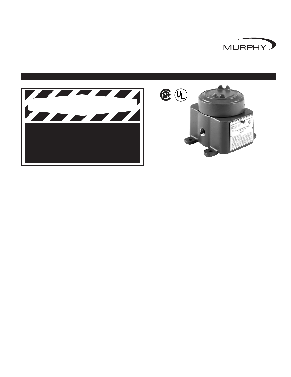
Shock/Vibration Control Switches
Installation Instructions
Models: VS2, VS2C, VS2EX, VS2EXR, VS2EXRB and VS94
GENERAL INFORMATION
Please read the following instructions before installing. A visual inspection of this product for damage during shipping is recommended before
mounting. It is your responsibility to have a qualified person install the unit, and make sure installation conforms with NEC and local codes.
Model VS2EX
LISTED
*
BEFORE BEGINNING INSTALLATION OF THIS MURPHY PRODUCT
✔✔
Disconnect all electrical power to the machine.
✔✔
Make sure the machine cannot operate during installation.
✔✔
Follow all safety warnings of the machine manufacturer.
✔✔
Read and follow all installation instructions.
VS-7037N
Revised 04-05
Section 20
(00-02-0185)
R
VS-7037N page 1 of 8
Description
The Murphy shock and vibration switches are available in a variety of
models for applications on machinery or equipment where excessive
vibration or shock can damage the equipment or otherwise poses a
threat to safe operation. A set of contacts is held in a latched position
through a mechanical latch and magnet mechanism. As the level of
vibration or shock increases an inertia mass exerts force against the
latch arm and forces it away from the magnetic latch causing the latch
arm to operate the contacts. Sensitivity is obtained by adjusting the
amount of the air gap between the magnet and the latch arm plate.
Applications include all types of rotating or reciprocating machinery
such as cooling fans, engines, pumps, compressors, pump jacks, etc.
Models
VS2: Base mount; non hazardous locations.
VS2C: C-clamp mount; non hazardous locations.
VS2EX: Explosion-proof; Class I, Div. 1,
Groups C and D.
VS2EXR: Explosion-proof with remote reset.
VS2EXRB: Explosion-proof; Class I, Div. 1, Group B; with
remote reset.
VS94: Base mount; non hazardous locations, NEMA 4X/IP66.
Remote Reset Feature (VS2EXR,
VS2EXRB and VS94 only)
Includes built-in electric solenoid which allows reset of tripped unit from a
remote location. Standard on VS2EXR and VS2EXRB. Optional on
VS94 (options listed below).
-R15: Remote reset for 115 VAC
-R24: Remote reset for 24 VDC
Time Delay Option (VS94 only)
Overrides trip operation on start-up. For VS94 series models, the delay
time is field-adjustable from 5 seconds up to 6-1/2 minutes with a 20turn potentiometer (15 seconds per turn approximately). Options listed
below:
-T15: Time delay for 115 VAC
-T24: Time delay for 24 VDC
Space Heater Options (VS94 only)
This optional space heater board prevents moisture from condensing
inside the VS94 Series case. Options listed below:
-H15: Space heater for 115 VAC
-H24: Space heater for 24 VDC
Warranty
A limited warranty on materials and workmanship is given with this FW
Murphy product. A copy of the warranty may be viewed or printed by going
to www.fwmurphy.com/support/warranty.htm
WARNING
Page 2
VS-7037N page 2 of 8
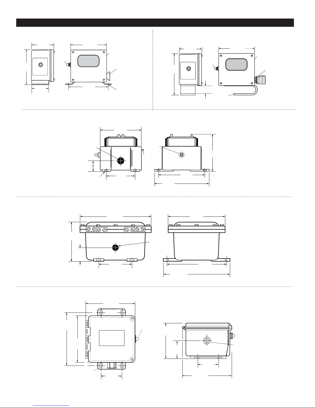
DIMENSIONS
3 in.
(76 mm)
4-3/4 in.
(121 mm)
2-1/4 in.
(57 mm)
5-1/8 in.
(130 mm)
Mounting Holes
Slotted
Sensitivity
Adjustment
Reset
Push
Button
4-19/32 in.
(116 mm)
Plug
1/4 x 1/2 in.
(6 mm x 13 mm)
Slot 2 places
3 in.
(76 mm)
4-3/4 in.
(121 mm)
Slotted
Sensitivity
Adjustment
5-7/16 in.
(138 mm)
Reset
Push
Button
Weatherproof
Strain Relief
Bushing
C-Clamp
27/32 in.
(21 mm)
1/2 NPT
Conduit
5-5/8 in.
(143 mm)
3 in.
(76 mm)
Mounting Holes
Reset
Push
Button
Slotted
Sensitivity
Adjustment
5-1/4 in.
(133 mm)
Mounting Holes
4-7/8 in.
(124 mm)
6-3/8 in.
(162 mm)
3/8 in.
(10 mm)
4 places
1-3/4 in.
(44 mm)
10-5/8 in.
(270 mm)
6 in.
(152 mm)
4-1/2 in.
(114 mm)
Mounting Centers
1/2 NPT
Conduit
9-1/8 in.
(232 mm)
Mounting Centers
10-3/16 in.
(259 mm)
8-5/8 in.
(219 mm)
2-1/2 in.
(64 mm)
VS2
VS2C
VS2EX and VS2EXR
VS2EXRB
7-9/64 in.
(181 mm)
4 in.
(102 mm)
6-1/2 in.
(165 mm)
6-29/32 in.
(176 mm)
Manual
Reset
Push-button
Mounting slot
5/16 x 9/16 in.
(8 x 14 mm)
4-places.
6-1/2 in.
(165 mm)
4-5/8 in.
(118 mm)
1-5/8 in.
(41 mm)
4 in.
(102 mm)
3/4 NPT
conduit fitting
VS94
Page 3
VS-7037N page 3 of 8
SPECIFICATIONS
VS2 and VS2C
•
Case: Weatherproof (equal to NEMA 3R) suitable for non-hazardous areas.
VS2: Base mount
VS2C: C-clamp mount. Includes 45 feet (13.7 meters), 2-conductor 16
AWG, 30 strands/0.25 mm strand dia. (1.5 mm2) cable, and five cable
hold down clamps.
•
Contacts: SPDT double make leaf contacts, 5A @ 480 VAC.
•
Range adjustment: 0 - 7 G’s; 0 - 100 Hz /0.100 in. displacement.
VS2EX
•
Case: Explosion-proof and weatherproof aluminum alloy housing;
meets NEMA 7/IP50 specifications; Class I, Division 1, Groups C &
D; UL and CSA listed.*
VS2EX: base mount.
•
Snap-switches: 2-SPDT snap-switches; 5A @ 480 VAC;*
2A resistive, 1A inductive, up to 30 VDC.
•
Range adjustment: 0 - 7 G’s; 0 - 100 Hz /0.100 in. displacement.
•
Normal Operating Temperature: -40 to 140°F (-40 to 60°C).
VS2EXR
•
Case: Same as VS2EX.
•
Snap-switch: 1-SPDT snap-switch and reset coil; 5A @ 480 VAC;*2A
resistive, 1A inductive, up to 30 VDC.
•
Remote Reset (optional):
Option Operating Current
-R15: 350 mA @ 115 VAC
-R24: 350 mA @ 24 VDC
•
Range adjustment: 0 - 7 G’s; 0 - 100 Hz /0.100 in. displacement.
•
Normal Operating Temperature: -40 to 140°F (-40 to 60°C).
VS2EXRB
•
Case: Explosion-proof aluminum alloy housing; rated Class I,
Division 1, Group B hazardous areas.
•
Snap-switch: 1-SPDT snap-switch with reset coil (option available for
additional SPDT switch); 5A @ 480 VAC; 2A resistive, 1A inductive,
up to 30 VDC.
•
Remote Reset:
Option Operating Current
-R15: 350 mA @ 115 VAC
-R24: 350 mA @ 24 VDC
•
Range adjustment: 0 - 7 G’s; 0 - 100 Hz /0.100 in. displacement.
VS94
•
Case: Polyester fiberglass reinforced; NEMA type 4 and 4X; IP66; CSA
types 4 and 12.
•
Conduit Fitting: 3/4 NPT conduit fitting connection.
•
Normal Operating Ambient Temperature:
0 to 140°F (-18 to 60°C).
•
Snap-switches: 2-SPDT snap acting switches; 5A @ 480 VAC; 2A
resistive, 1A inductive, up to 30 VDC.
•
Range adjustment: 0 - 7 G’s; 0 - 100 Hz /0.100 in. displacement.
•
Heater (optional):
Option Operating Current
H15 .023 A @ 115 VAC
H24 .12 A @ 24 VDC
•
Remote Reset (optional):
Option Operating Current
R15 .17 A @ 115 VAC
R24 .36 A @ 24 VDC
•
Time Delay (optional):
Option Operating Current Standby Current
T15 .360 A @ 115 VAC .01 A @ 115 VAC
T24 1.15 A @ 24 VDC .01 A @ 24 VDC
•
Time Delay/Remote Reset: Adjustable 20-turn potentiometer from
5 seconds to 6-1/2 minutes (15 seconds per turn approximately).
*CSA and UL listed with 480 VAC rating.
The VS2 and VS94 series shock switches are sensitive to shock and
vibration in all three planes of motion - up/down, front/back and side/side.
Front/back is the most sensitive (The reset pushbutton is located on the
“front” of the unit). For maximum sensitivity mount the unit so that the
front faces into the direction of rotation of the machine. (See Dimensions on
page 2 for sensitivity adjustment location).
The VS2 and VS94 Series must be firmly attached/mounted to the machine
so that all mounting surfaces are in rigid contact with the mounting surface
of the machine. For best results, mount the instrument in-line with the
direction of rotating shafts and/or near bearings. In other words, the reset
push button should be mounted pointing into the direction of shaft rotation
(see page 5). It may be necessary to provide a mounting plate or bracket to
attach the VS2 and VS94 Series to the machine. The mounting bracket
should be thick enough to prevent induced acceleration/vibration upon the
VS2 or VS94 Series. Typically 1/2 in. (13mm) thick plate is sufficient. See
illustrations on page 5 for typical mounting locations.
CAUTION:
A dust boot is provided on the reset pushbutton
for all series to prevent moisture or dust intrusion. The sensitivity
adjustment for model VS2EX is not sealed; therefore, mounting
orientation should be on a horizontal plane or with the sensitivity adjustment
pointing down. Sensitivity adjustment for model VS2 is covered by a plug.
The plug must be in place and tight to prevent moisture or dust intrusion.
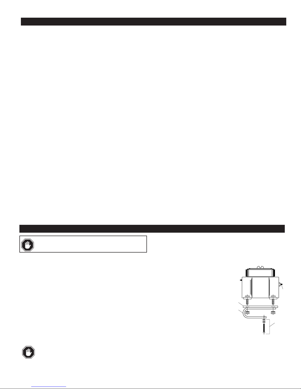
C-Clamp Installation (VS2C model only)
A C-Clamp is supplied with the VS2C model only.
The C-Clamp is shipped installed on the VS2C
but must be installed on the VS2EX and
VS2EXR switches.
1. The C-Clamp (B) will already be installed on
a 1/4 in. (6 mm) thick steel mounting plate
(A). Bolt the VS2 switch to the mounting
plate as illustrated — with four 5/16 in.
bolts, nuts, and washers.
2. The mounting location should provide
convenient access to the TATTLETALE
®
push button (C).
3. The hardened set screw and nuts (D) are used to
tighten the switch to an I-Beam or cross member such as a
Sampson post of an oilwell pumpjack.
WARNING: STOP THE MACHINE AND DISCONNECT ALL
ELECTRICAL POWER BEFORE BEGINNING INSTALLATION.
INSTALLATION
Continued on next page.
A
B
C
D
Page 4

All Models
1. Firmly secure the unit to the equipment using the base foot mount or
C-Clamp if applicable. See C-Clamp Installation page 3.
For oilwell pumpjacks attach the VS2 and VS94 Series to the Sampson
post or walking beam. See Typical Mounting Locations page 5.
2. Make the necessary electrical connections to the vibration switch. See
Internal Switches, page 6 for electrical terminal locations and page 7 for
typical wiring diagrams. DO NOT EXCEED VOLTAGE OR CURRENT
RATINGS OF THE CONTACTS. Follow appropriate electrical
codes/methods when making electrical connections. Be sure that the run of
electrical cable is secured to the machine and is well insulated from
electrical shorting. Use of conduit is recommended.
NOTE: If the electrical cable crosses a pivot point such as at the pivot of
the walking beam, be sure to allow enough slack in the cable so that no
stress is placed on the cable when the beam moves.
If conduit is not used for the entire length of wiring, conduit should be
used from the electrical supply box to a height above ground level that
prevents damage to the exposed cable from the elements, rodents, etc. or
as otherwise required by applicable electrical codes. If conduit is not
attached directly to the VS2 and VS94 Series switch, use a strain relief
bushing and a weatherproof cap on the exposed end of the conduit. A
“drip loop” should be provided in the cable to prevent moisture from
draining down the cable into the conduit should the weathercap fail.
Sensitivity Adjustment
All models of the VS2 and VS94 Series cover a wide range of sensitivity.
Each model is adjusted to the specific piece of machinery on which it is
installed. After the switch has been installed in a satisfactory location (see
page 5) the sensitivity adjustment will be increased or decreased so that the
switch does not trip during start-up or under normal operating conditions.
This is typically done as follows:
1. REPLACE ALL COVERS, LIDS, AND
ELECTRICAL ENCLOSURES.
2. Press the reset push button to engage the magnetic latch. To be sure the
magnetic latch has engaged, observe latch
through the window on the VS2 and
VS2C (see DETAIL “A”). On the
VS2EX, VS94 series the reset button
will remain depressed meaning the
magnetic latch has engaged.
3. Start the machine.
4. If the instrument trips on start-up,
allow the machine to stop. Turn the sensitivity adjustment 1/4 turn
clockwise, (adjustment for VS94 and VS2EXRB models is located within
the box, see DETAIL “B”).
Depress the reset button and restart the machine. Repeat this process until
the unit does not trip on start-up.
5. If the instrument does NOT trip on start-
up, stop the machine. Turn the sensitivity
adjustment 1/4 turn counter-clockwise.
Repeat the start-up/stop process until the
instrument trips on start-up. Turn the
sensitivity adjustment 1/4 turn clockwise
(less sensitive). Restart the machine to
verify that the instrument will not trip on
start-up.
6. Verify that the unit will trip when abnormal shock/vibration exists.
VS94 Time Delay Adjustment
1. Apply power to the time delay circuit. (see
page 7 for time delay circuit). The time delay function will be initiated.
2. Time the length of the delay with a watch. Let time delay expire. After it
expires, the override circuit will de-energize the solenoid, allowing the latch
arm to trip. A clicking noise is heard.
3. TURN THE POWER OFF TO RESET THE TIME DELAY CIRCUIT.
NOTE: Allow 30 seconds bleed-time between turning the
power “OFF” and “ON”.
4. Locate the time adjustment pot (DETAIL “C”).
The time is factory-set at the lowest setting (5
seconds approximately). To increase time,
rotate the 20-turn pot clockwise as needed
(15 seconds per turn approximately).
5. Repeat the above steps as necessary to
obtain desired time delay.
NOTE: An external time delay can be used
with the remote reset feature of the VS2EXR
series to provide a remote reset and override of the trip
operation on start-up. Time delay must automatically disconnect after
equipment start-up.
VS-7037N page 4 of 8
INSTALLATION
Continued
WARNING: STOP THE MACHINE AND DISCONNECT ALL
ELECTRICAL POWER BEFORE BEGINNING INSTALLATION.
DETAIL “A”
Sensitivity
Adjustment
Reset Push button
DETAIL “C”
Turn to
increase
Pot
Turn to
decrease
WARNING: MAKE THE AREA NON-HAZARDOUS BEFORE
OPENING THE EXPLOSION-PROOF (-EX) ENCLOSURES.
WARNING: REMOVE ALL POWER BEFORE OPENING
THE ENCLOSURE. IT IS YOUR RESPONSIBILITY TO HAVE A
QUALIFIED PERSON PERFORM ADJUSTMENTS, AND MAKE
SURE IT CONFORMS WITH NEC AND LOCAL CODES. DO
NOT ADJUST SENSITIVITY WHILE THE MACHINE IS RUNNING. STAND
CLEAR OF THE MACHINE AT ALL TIMES WHEN IT IS OPERATING.
WARNING: REMOVE ALL POWER BEFORE OPENING
ACCESS DOOR. IT IS YOUR RESPONSIBILITY TO HAVE A
QUALIFIED PERSON ADJUST THE UNIT, AND MAKE SURE
IT CONFORMS WITH NEC AND LOCAL CODES.
DETAIL “B”
Less
Sensitive
Sensitivity
adjustment
More Sensitive
Page 5

VS-7037N page 5 of 8
TYPICAL MOUNTING LOCATIONS
Engine Compressor
Turbine Centrifugal
Compressor
Engine
and
Vertical
Shaft
Pump
“Y” Type
Reciprocating
Compressor
Generator
Sets
Cooling Tower Fan or
Heat Exchanger
Pumping Unit
2-Throw Balance-Opposed Compressor
NOTE: If installing on
cylinders, 2 vibration/shock
switches are recommended1 for each cylinder.
Reset
Reset
Reset
Reset
Reset
These are typical mounting locations for best operation. Other mountings are possible.
See
Installation
section on page 3.
NOTE:
Reset
Reset
Reset
Reset
Page 6

VS-7037N page 6 of 8
INTERNAL SWITCHES
VS2 and VS2C VS2EXR
NO1 NC COM NO2
SPDT Switch Terminals
Sensitivity
Adjustment
Remote Reset
Terminal
Sensitivity
Adjustment
NC NO COM
Ground
Terminal
SPDT Snap-Switch
VS2EX
SPDT Snap-Switch
SPDT Snap-Switch
NC NO COM
NC NO COM
Sensitivity
Adjustment
Ground
Terminal
SPDT
Snap-Switch
VS94
VS2EXB and VS2EXRB
NC NO COM
SPDT
Snap-Switch
Time Delay and/or
Remote Reset
Terminal (Optional)
NC NO COM
Remote Reset
Terminal
Sensitivity
Adjustment
Ground
Terminal
Optional SPDT
Snap-Switch
(VS2EXRB only)
SPDT
Snap-Switch
NC NO COM
NC NO COM
Ground
Terminal
Sensitivity
Adjustment
Heater Board
Terminal (Optional)
Page 7

VS-7037N page 7 of 8
WARNING: REMOVE POWER BEFORE OPENING THE UNIT (ACCESS DOOR). STOP THE MACHINE AND DISCONNECT ALL
ELECTRICAL POWER BEFORE BEGINNING THE WIRING OPERATION. IT IS YOUR RESPONSIBILITY TO HAVE A QUALIFIED
PERSON INSTALL AND WIRE THE UNIT, AND MAKE SURE IT CONFORMS WITH NEC AND APPLICABLE CODES.
ELECTRICAL
Typical Wiring Diagram for Single or Dual CD Ignition
VS2 and VS2C
Resistor
SPDT Switch
COM
To good
engine ground
CD Ignition
2
Contacts shown in the RESET position.
(100 Ω, 3 Watt)
CD Ignition
1
VS2EXR and VS2EXRB
Typical Wiring Diagram for Single or Dual CD Ignitions
SPDT Switch
(Optional 2-SPDT [DPDT])
Contacts shown in the
RESET position
N.C.N.O.
N.C.N.O.
Momentary
Push Button
115 VAC or
Voltage
24 VDC (
is specified
when ordered).
Remote Reset
Typical Wiring Diagram for Single or Dual CD Ignitions
VS2EX
SPDT Switch
(Optional 2-SPDT [DPDT])
Contacts shown in the
RESET position
NO2NCNO1
CD Ignition
2
CD Ignition
1
Resistor
(100 Ω, 3 Watt)
N.C.N.O.
N.C.N.O.
†
COM
COM
To good
engine ground
To good
engine
ground
VS94
Typical Wiring Diagram for Single or Dual CD Ignitions
2-SPDT
Switches (DPDT)
Contacts shown in the
RESET position
N.C.N.O.
N.C.N.O.
COM
COM
To good
engine
ground
COM
COM
†
To good
engine
ground
†
Additional
Switch
Optional
on VS2EXRB
only
Momentary
Contact for
Remote
Reset only
Maintained
Contact for
Time Delay
115 VAC or
24 VDC
Time Delay or
Remote Reset
(Optional)
115 VAC or 24 VDC
Time
Delay
*
*
CD Ignition
2
CD Ignition
Resistor
(100 Ω, 3 Watt)
1
VS2, VS2C, VS2EX, VS2EXR, VS2EXRB and VS94
Typical Wiring Diagram for Electric Motors
NOTE: Terminal N.O. is
terminal NO1 on models
VS2 and VS2C.
L1 L2 L3
MOTOR
Switch Terminals
N.O.
(see Note)
Push-button
Station
HC
N.C.
Hand Off
Automatic
Selector
HC
To good
engine ground
Contacts shown
in the RESET position
COM
A
H
1
Heater Board
(Optional)
Resistor
(100 Ω, 3 Watt)
To good
engine ground
*
Voltage is specified
when ordered.
CD Ignition
VS2, VS2C, VS2EX, VS2EXR, VS2EXRB and VS94
Typical Wiring Diagram for Distributor Ignition or Diesel
NOTE: Terminal N.O. is
terminal NO1 on models
VS2 and VS2C.
Diesel Fuel
Shutoff Valve
Ignition Coil
Switch Terminals
N.O.
(see Note)
Distributor
N.C.
Contacts shown
in the RESET position
COM
Ignition
Switch
Ammeter
Battery
CD Ignition
2
Page 8

VS-7037N page 8 of 8
SERVICE PARTS
PART NO. DESCRIPTION
VS2
20000030 Movement assembly
20000031 Glass and gasket assembly
20000032 Reset push button assembly
VS2C
20000030 Movement assembly
20000031 Glass and gasket assembly
20000032 Reset push button assembly
20050021 Mounting clamp
20000185 VS2C 5-clamp hardware package assembly.
20050465 2-Conductor electrical cable, 45 feet (13.7 meters)
VS2EX
20010091 Movement assembly
20050087 Cover
00000309 Cover gasket
20010090 Snap-switch and insulator kit (1 switch per kit)
prior to September 1, 1995.*
20000288 Snap-switch and insulator kit (1 switch per kit) for models
manufactured on September 1, 1995 or later.*
20000289 C-clamp conversion mounting kit
VS2EXR
20000262 Movement assembly
20050087 Cover
00000309 Cover gasket
20010090 Snap-switch and insulator kit (1 switch per kit)
prior to September 1, 1995.*
20000288 Snap-switch and insulator kit (1 switch per kit) for models
manufactured on September 1, 1995 or later.*
20000049 Reset solenoid assembly (115 VAC)
20000234 Reset solenoid assembly (24 VDC)
20000289 C-clamp conversion mounting kit
PART NO. DESCRIPTION
VS2EXRB
20010090 Snap-switch and insulator kit (1 switch per kit)
prior to September 1, 1995.*
20000288 Snap-switch and insulator kit (1 switch per kit) for models
manufactured on September 1, 1995 or later.*
20000057 Inside snap-switch and insulator kit (1 switch per kit) for
model VS2EXRB-D prior to September 1, 1995.*
20000058 Outside snap-switch and insulator kit (1 switch per kit) for
model VS2EXRB-D prior to September 1, 1995.*
20000287 Outside snap-switch and insulator kit (1 switch per kit) for model
VS2EXRB-D manufactured on September 1, 1995 or later.*
20000290 Inside snap-switch and insulator kit (1 switch per kit) for model
VS2EXRB-D manufactured on September 1, 1995 or later.*
20050077 Adjustment shaft
20000262 Movement assembly
20000049 Reset solenoid assembly (115 VAC)
20000234 Reset solenoid assembly (24 VDC)
VS94 Series
25050506 Dust boot
00000232 Conduit fitting
20010090 Snap-switch and insulator kit (1 switch per assembly)
prior to September 1, 1995.**
20000288 Snap-switch and insulator kit (1 switch per assembly)
for models manufactured on September 1, 1995 or later.***
* If no date code is found, refer to the old switch. Models with date 0895 and before use old switch.
Dated 0995 after, use straight snap-switch arm, no rollers.
** Models dated Q1 thru Q8 (formed snap-switch arm and rollers).
***Models date coded Q9 thru Q12 and R1 thru R12 (straight snap-switch arm, no rollers).
CONTROL SYSTEMS & SERVICES DIVISION
P.O. Box 1819; Rosenberg, Texas 77471; USA
+1 281 633 4500 fax +1 281 633 4588
e-mail sales@fwmurphy.com
INDUSTRIAL PANEL DIVISION
P.O. Box 470248
Tulsa, Oklahoma 74147 USA
+1 918 317 4100 fax +1 918 317 4266
e-mail sales@fwmurphy.com
FRANK W. MURPHY, LTD.
Church Rd.; Laverstock, Salisbury SP1 1QZ; U.K.
+44 1722 410055 fax +44 1722 410088
e-mail sales@fwmurphy.co.uk
www.fwmurphy.co.uk
MURPHY DE MEXICO, S.A. DE C.V.
Blvd. Antonio Rocha Cordero 300, Fracción del Aguaje
San Luis Potosí, S.L.P.; México 78384
+52 444 8206264 fax +52 444 8206336
Villahermosa Office +52 993 3162117
e-mail ventas@murphymex.com.mx
www.murphymex.com.mx
In order to consistently bring you the highest quality, full featured products, we reserve the right to change our specifications and designs at any time.
FW Murphy
P.O. Box 470248
Tulsa, Oklahoma 74147 USA
+1 918 317 4100 fax +1 918 317 4266
e-mail sales@fwmurphy.com
www.fwmurphy.com
Printed in U.S.A. 078792
 Loading...