

Page 1
VS-96013B page 1 of 4
VS2 Series
■
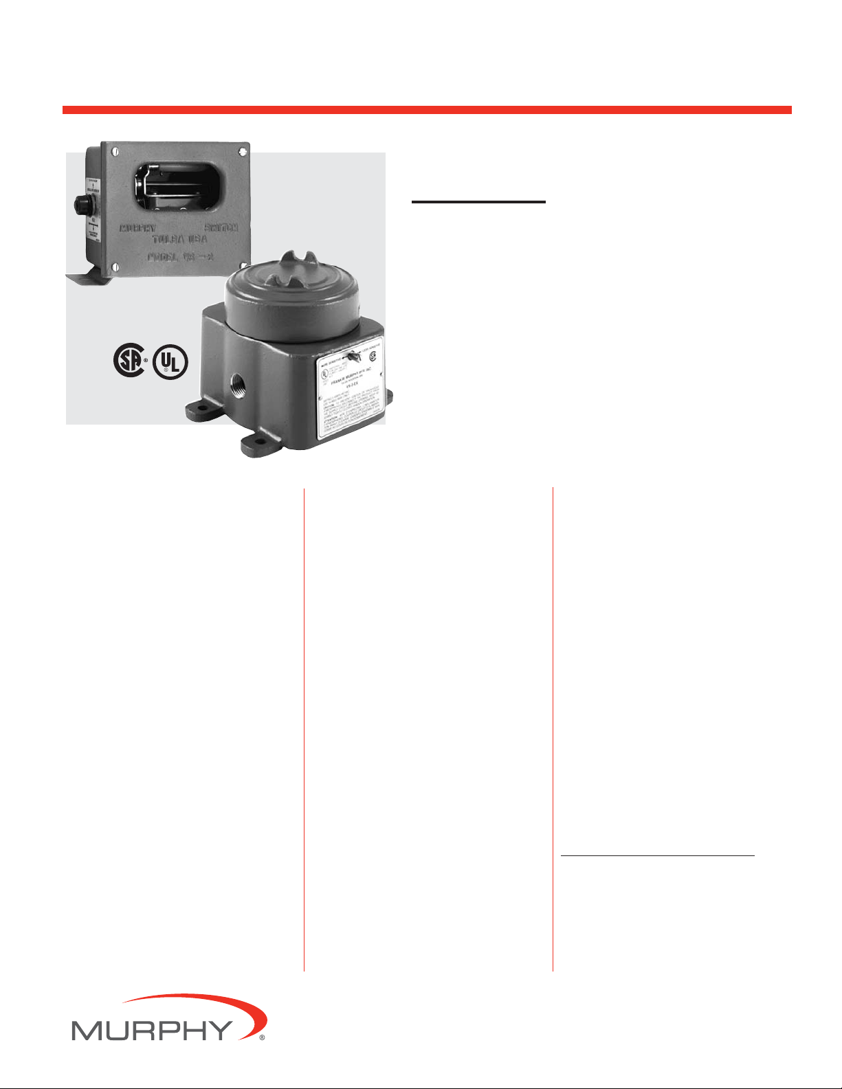
Designed to Detect Shock/Vibration
in 3-Planes of Motion
■
Fully Adjustable
■
Includes Magnetic Latching Feature
■
Manual or Electric Reset
Description
The VS2 Series switches are shock sensitive
mechanisms for shutdown of engine or electric motor powered equipment. These
switches use a magnetic latch to ensure reliable operation. Explosion-proof “EX” models for hazardous locations are available.
Applications
Ideal for use on engines, pumps, compressors, heat exchangers and pumping units, the
VS2 Series can be used anywhere shutdown
protection from damaging shock/vibration is
desired. Switches are field adjustable to sensitivity required in each application.
Specifications
VS2 and VS2C
Case: Equal to NEMA 3R. Suitable for
non-hazardous areas.
VS2: Base mount
VS2C: C-clamp mount, includes 45 ft. (13.7 m)
2-conductor cable, and 5 cable clamps.
Contacts: SPDT-double make leaf contacts,
5A @ 480 VAC.
VS2EX
Case: Base mount, explosion-proof aluminum
alloy housing; meets NEMA 7/IP50 specifications; Class I, Division 1, Groups C & D;
UL and CSA listed.*
Snap-switches: 2-SPDT snap-switches; 5A
@ 480 VAC;* 2A resistive, 1A inductive,
up to 30 VDC.
Normal Operating Temperature: -40 to
140°F (-40 to 60°C).
VS2EXR
Case: Same as VS2EX.
Snap-switch: 1-SPDT snap-switch and reset
coil; 5A @ 480 VAC;* 2A resistive, 1A
inductive, up to 30 VDC.
Remote Reset : 115 VAC or 24 VDC (specify).
VS2EXRB
Case: Explosion-proof aluminum alloy
housing; rated Class I, Division 1, Group
B hazardous areas.
Snap-switch: 1-SPDT snap-switch with
reset coil (option available for 2-SPDT
switches); 5A @ 480 VAC; 2A resistive,
1A inductive, up to 30 VDC.
Remote Reset: 115 VAC or 24 VDC (specify).
Basic Operation
Pushing the reset button moves the tripping
latch into a magnetically held position.
A shock/vibration will move the magnet
beyond this holding position, thus freeing
the spring loaded tripping latch to transfer
the contacts and shutdown the machinery
(see dimensional diagrams in the following
pages for visual representation of parts).
Remote Reset Option
(VS2EXR and VS2EXRB)
The remote reset option includes a builtin electric solenoid which allows reset of
tripped unit from a remote location.
Available for 115 VAC or 24 VDC.
Warranty
A limited warranty on materials and workmanship
is given with this FW Murphy product. A copy of
the warranty may be viewed or printed by going to
www.fwmurphy.com/support/warranty.htm
VS2EX
VS2
*CSA and UL listed with 480 VAC rating.
LISTED
*
VS-96013B
Revised 09-08
Catalog Section 20
00-02-0076
Shock and Vibration Switch
Page 2
VS-96013B page 2 of 4
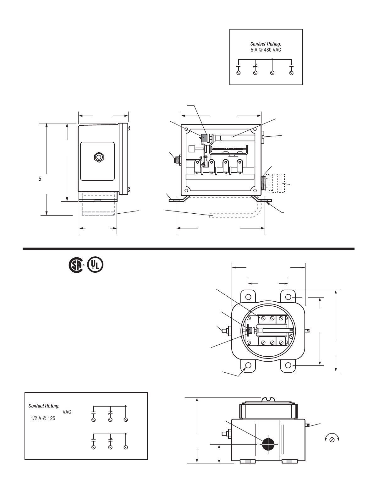
ELECTRICAL
Contact Rating:
5 A @ 480 VAC
VS2 and VS2C
VS2EX
• NEMA 7/IP50 Specifications
• Snap-switch Contacts
• TATTLETALE
®
Reset Button
The VS2 and VS2C are designed for use in non-hazardous locations. They have leaf type SPDT, double make contacts that can
be used for shutdown and/or alarm. They have a slotted sensitivity
adjustment located on the side of the case (see drawing below).
Model VS2EX is housed in an explosion-proof enclosure with
threaded cover. This enclosure is CSA and UL listed for Class I,
Division 1, Groups C & D hazardous locations. In place of the
leaf type contacts, 2-SPDT snap-switches are used in this model.
Sensitivity is externally adjustable and, when tripped, the VS2EX
gives a TATTLTALE
®
indication on the reset button. It is con-
structed to meet NEMA 7 specifications.
ELECTRICAL
Contact Rating:
5 A @ 125–480 VAC
1/2 A @ 125 VDC
1/4 A @ 250 VDC
2 A Resistive 30 VDC
1 A Inductive 30 VDC
2-SPDT Switches (DPDT)
NO1
COM
NO2NC
4-11/16 in.
(119 mm)
5-3/8 in.
(137 mm)
VS2C Model
SIDE VIEW FRONT VIEW
Air Gap
3-1/8 in.
(80 mm)
2-1/4 in.
(57 mm)
Permanent
Magnet
Reset
Push
Button
Mounting
Bracket
C-clamp
Mounting
Bracket
VS2C Model
(Cover removed)
NO1 NC COM NO2
5-1/8 in. (130 mm)
Mounting Holes
4-40 NC
Screw
Terminal
Permanent
Magnet
TATTLETALE
Reset Push
Button
Air Gap
(10 mm)
4-11/16 in.
(119 mm)
3/8 in.
4 places
Adjustment
Armature
Slotted Sensitivity
Adjustment
1/2 Conduit
Threads
Weatherproof
Strain Relief
Bushing (VS2C)
1/4 x 1/2 in.
(6 mm x 13 mm)
Slot 2 places
5-5/8 in. (143 mm)
3 in.
(76 mm)
Mounting
Holes
5-1/4 in.
®
NC NO COM
NC NO
COM
TOP VIEW
(Cover removed)
(133 mm)
Mounting
Holes
6-3/8 in.
(162 mm)
COM
N.C.N.O.
COM
N.C.N.O.
1/2 NPT
Conduit
4-7/8 in.
(124 mm)
(44 mm)
1-3/4 in.
SIDE VIEW
Slotted
Sensitivity
Adjustment
MORE
SENSITIVE
LESS
SENSITIVE
Page 3

VS2EXR
• Remote Reset Feature
• NEMA 7 Specifications
• Snap-switch Contacts
• TATTLETALE
®
Reset Button
Model VS2EXR features an electric remote reset feature in addition to the TATTLETALE
®
reset button. The VS2EXR uses only
one SPDT snap-switch and is CSA and UL listed for Class I,
Division 1, Groups C & D hazardous locations. It is constructed
to meet NEMA 7 specifications.
VS2EXRB
• For Group B Locations
• Snap-switch Contacts
• DPDT Feature Optional
Model VS2EXRB is constructed for use in Class I, Division 1,
Group B, hazardous locations. It has, as standard, a SPDT snapswitch and an electric remote reset. Option is available for DPDT
snap-switch.
ELECTRICAL
Contact Rating:
5 A @ 125–480 VAC
1/2 A @ 125 VDC
1/4 A @ 250 VDC
2 A Resistive 30 VDC
1 A Inductive 30 VDC
Remote Reset Rating:
115 VAC or 24 VDC (Specify)
350 mA AC/DC
Remote
Reset
SPDT
Snap-switch
ELECTRICAL
Contact Rating:
5 A @ 125–480 VAC
1/2 A @ 125 VDC
1/4 A @ 250 VDC
2 A Resistive 30 VDC
1 A Inductive 30 VDC
Remote Reset Rating:
115 VAC or 24 VDC (Specify)
350 mA AC/DC
N.C.N.O.
COM
N.C.N.O.
COM
Remote
Reset
Option SPDT
Snap-switch (DPDT)
SPDT
Snap-switch
VS-96013B page 3 of 4
Remote
Reset Coils
5-5/8 in. (143 mm)
3 in.
(76 mm)
Mounting
Holes
N.C.N.O.
COM
TATTLETALE
Reset Push
Button
4-40 NC
Screw Terminal
4-7/8 in.
(124 mm)
Permanent
Magnet
Air Gap
3/8 in.
(10 mm)
4 places
1/2 NPT
Conduit
1-3/4 in.
(44 mm)
5-1/4 in.
(133 mm)
®
NC NO COM
TOP VIEW
(Cover removed)
SIDE VIEW
Mounting
Holes
Slotted
Sensitivity
Adjustment
MORE
SENSITIVE
6-3/8 in.
(162 mm)
LESS
SENSITIVE
9-1/8 in.
(232 mm)
Mounting
Centers
6 in.
(152 mm)
6 in.
(152 mm)
2-1/2 in.
(64 mm)
10-5/8 in.
(270 mm)
TOP VIEW
(Cover removed)
8 in.
(203 mm)
NC NO COM
8-5/8 in.
(219 mm)
1/2 NPT
Conduit
10-3/16 in.
(259 mm)
4-1/2 in.
(114 mm)
Mounting Centers
SIDE VIEW
Page 4

How to Order
To order your VS2 Series model use the diagram below.
Part number example: VS2EXR-24
___ – ___
Options
24 = 24 VDC reset coil on VS2EXR or VS2EXRB
15 = 115 VAC reset coil on VS2EXR or VS2EXRB
D = DPDT switch on VS2EXRB only
LC = Less case
LCC = Less cable and clamps on VS2C
Base Model
VS2
VS2C
VS2EX
VS2EXR
VS2EXRB
NOTE: Order C-clamp
mounting kit as a separate
line item for VS2EX and
VS2EXR.
Service Parts
When ordering service parts, specify both part number and description in listing below.
PART NO. DESCRIPTION
VS2 and VS2C
20-00-0030 Movement assembly
20-00-0031 Glass and gasket assembly
20-00-0032 Reset push button assembly
20-05-0021 Mounting clamp (VS2C)
20-00-0261 Cable clamp assembly (1 each) (VS2C)
20-05-0465 2-Conductor electrical cable, 45 feet (13.7 meters) (VS2C)
20-00-0137 5 clamps and 45 feet (13.7 meters) of cable (VS2C)
VS2EX
20-01-0091 Movement assembly
20-05-0087 Cover
00-00-0309 Cover gasket
20-01-0090 Snap-switch and insulator kit (1 switch per kit)
prior to September 1, 1995.*
20-00-0288 Snap-switch and insulator kit (1 switch per kit) for models
manufactured on September 1, 1995 or later.*
20-00-0289 C-clamp conversion mounting kit
VS2EXR
20-00-0262 Movement assembly
20-05-0087 Cover
00-00-0309 Cover gasket
20-01-0090 Snap-switch and insulator kit (1 switch per kit)
prior to September 1, 1995.*
20-00-0288 Snap-switch and insulator kit (1 switch per kit) for models
manufactured on September 1, 1995 or later.*
20-00-0049 Reset solenoid assembly (115 VAC)
20-00-0234 Reset solenoid assembly (24 VDC)
20-00-0289 C-clamp conversion mounting kit
VS2EXRB
20-01-0090 Snap-switch and insulator kit (1 switch per kit)
prior to September 1, 1995.*
20-00-0288 Snap-switch and insulator kit (1 switch per kit) for models
manufactured on September 1, 1995 or later.*
20-00-0057 Inside snap-switch and insulator kit (1 switch per kit) for
model VS2EXRB-D prior to September 1, 1995.*
20-00-0058 Outside snap-switch and insulator kit (1 switch per kit) for
model VS2EXRB-D prior to September 1, 1995.*
20-00-0287 Outside snap-switch and insulator kit (1 switch per kit) for model
VS2EXRB-D manufactured on September 1, 1995 or later.*
20-00-0290 Inside snap-switch and insulator kit (1 switch per kit) for model
VS2EXRB-D manufactured on September 1, 1995 or later.*
20-05-0077 Adjustment shaft
20-00-0262 Movement assembly
20-00-0049 Reset solenoid assembly (115 VAC)
20-00-0234 Reset solenoid assembly (24 VDC)
* Models with date 0895 and before use old switch. Dated 0995 after, use straight snap-switch
arm, no rollers.
Shipping Information
VS2 and VS2C
Shipping Weight:
VS2: 2 lb 8 oz. (1.1 kg)
VS2C: 7 lb (3.2 kg)
Shipping Dimensions:
VS2: 8-1/4 x 9-1/4 x 5 in. (210 x 235 x 127 mm)
VS2C: 12 x 7 x 5-1/2 in. (305 x 178 x 140 mm)
VS2EX
Shipping Weight: 4 lb 8 oz. (2 kg)
Shipping Dimensions: 8-1/4 x 9-1/4 x 5 in. (210 x 235 x 127 mm)
VS2EXR
Shipping Weight: 5 lb 8 oz. (2.2 kg)
Shipping Dimensions: 8-1/4 x 9-1/4 x 5 in. (210 x 235 x 127 mm)
VS2EXRB
Shipping Weight: 17 lb 8 oz. (7.9 kg)
Shipping Dimensions: 12 x 12 x 10 in. (305 x 305 x 254 mm)
VS-96013B page 4 of 4
FRANK W. MURPHY, LTD
Church Rd Laverstock
Salisbury SP1 1QZ UK
Phone: +44 172 241 0055 Fax: +44 172 241 0088
E-mail: sales@fwmurphy.co.uk
Web site: www.fwmurphy.co.uk
COMPUTRONIC CONTROLS, LTD
41 - 43 Railway Terrace
Nechells, Birmingham B7 5NG UK
Phone: +44 121 327 8500 Fax: +44 121 327 8501
E-mail: sales@computroniccontrols.com
Web site: www.computroniccontrols.com
FW MURPHY INSTRUMENTS (HANGZHOU) CO. LTD
77 23rd Street
Hangzhou Economic & Technological Development Area
Hangzhou, Zhejiang 310018 China
Phone: +86 571 8788 6060 Fax: +86 571 8684 8878
FW MURPHY INTERNATIONAL TRADING (SHANGHAI) CO., LTD.
Suite 1704, Tower B, City Center of Shanghai; 100 Zunyi Road
Shanghai, 200051 China
Phone: +86 21 6237 2082 Fax: +86 21 6237 2083
Web site: mhong@fwmurphy.com
FW MURPHY
P.O. Box 470248
Tulsa, Oklahoma 74147 USA
+1 918 317 4100 Fax: +1 918 317 4266
E-mail: sales@fwmurphy.com
INDUSTRIAL PANEL DIVISION
Fax: +1 918 317 4124
E-mail: ipdsales@fwmurphy.com
MURPHY POWER IGNITION
Web site: www.murphy-pi.com
CONTROL SYSTEMS & SERVICES DIVISION
P.O. Box 1819
Rosenberg, Texas 77471 USA
Phone: +1 281 633 4500 Fax: +1 281 633 4588
E-mail: sales@fwmurphy.com
Printed in U.S.A.
www.
fwmurphy
.com
 Loading...