

Page 1
TTDJ-99062N page 1 of 8
TTDJ Series Fully-Configurable Fault Annunciator
Installation and Operations Manual
TTDJ-99062N
Revised 04-04
Section 50
(00-02-0412)
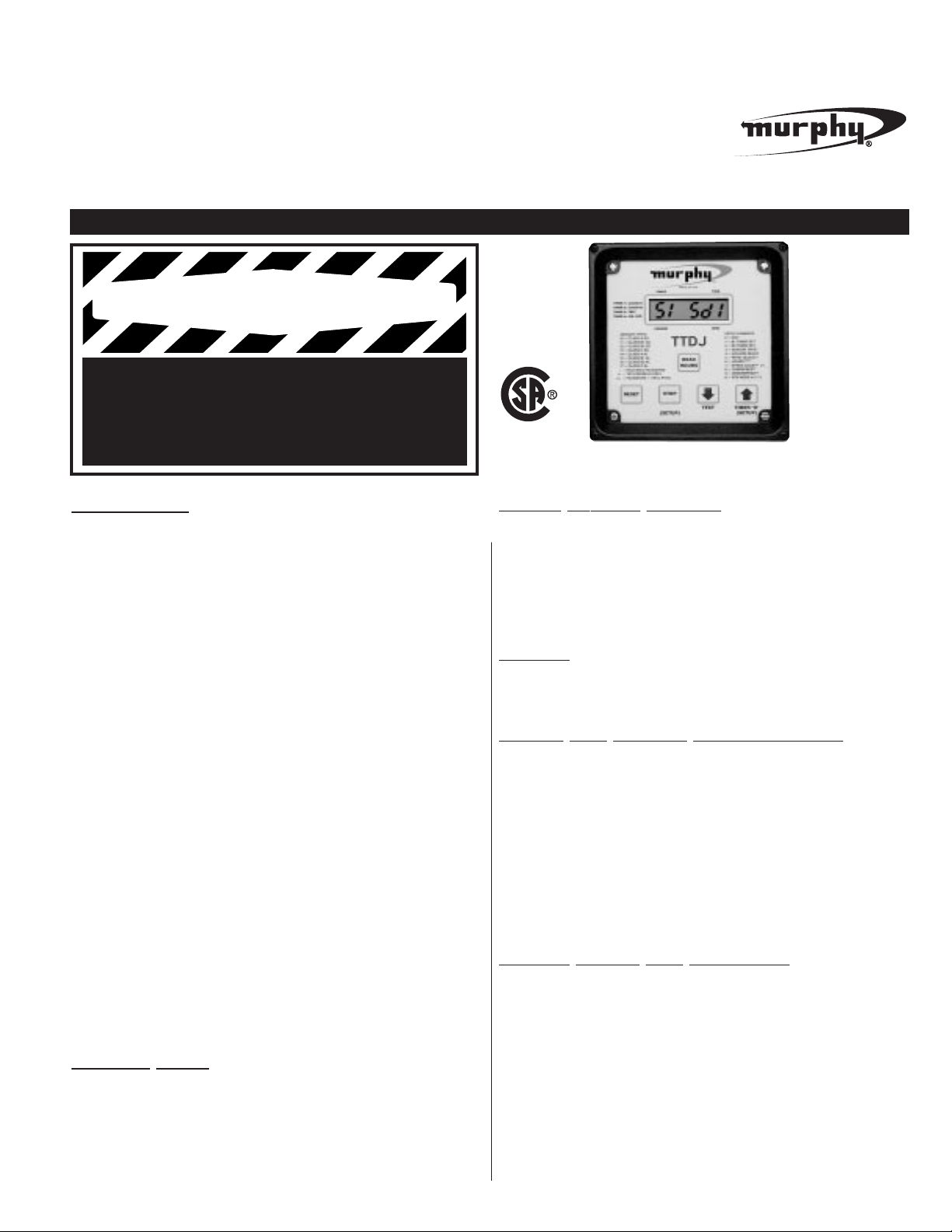
Description
The TTDJ is a solid-state fault annunciator and shutdown control system,
with hour meter, designed to protect engines, compressors and their associated equipment. Four TTDJ modules are available:
TTDJ-DC
:
Powered by 12 or 24 VDC systems without tachome-
ter and overspeed sensing. Includes RS485 serial port.
TTDJ-DC-T: Powered by 12 or 24 VDC systems with internal
tachometer and overspeed sensing. Includes RS485 serial port.
TTDJ-IGN: Powered by negative ground CD ignition systems
without tachometer and overspeed sensing. Without RS485 port.
TTDJ-IGN-T
:
Powered by negative ground CD ignition systems
with internal tachometer/overspeed sensing.Without RS485 port.
All TTDJ models will accept 32 sensor inputs from normally open and/or
normally closed sensors. Each of the first 16 inputs can be configured for
Shutdown or Alarm Before Shutdown
*
, and can be locked out by one of
the Two Start-Run timers (B1:0-5 min.; B2:0-9:59 min.), or configured as
Class C. The annunciator provides for both closing of a fuel valve, and
grounding of an ignition after a time delay. The TTDJ has built-in Elapsed
Time Meter. Run Hours and Tachometer Settings are stored in nonvolatile memory, as well as the last 4 shutdowns and one alarm (alarm
only stored if active at the time of shutdown). The TTDJ liquid crystal
display annunciates any fault from the sensor inputs, displays engine
speed and elapsed time.
Other features for all TTDJ models are: built-in Test Mode to test the sensor
circuits without shutting down, on-board backup battery to retain the fault
display after shutdown (IGN models only), and a history of the last 4 shutdowns with their associated Run Hours, also stored in non-volatile memory.
TTDJ-DC and TTDJ-DC-T models feature an RS485 serial communications
port (MODBUS RTU slave) to interface with micro-controllers, PC’S,
PLC’s and controllers.
Module/ Head
The module is the brain of the control system. It contains the microcomputer, the Liquid Crystal Display (LCD), the membrane keys for configuring the sensors inputs, the Sensor Inputs Terminal Blocks and the Power
Inputs and Control Output Terminal Block. The TTDJ-DC module also
includes an RS485 serial communications port (MODBUS RTU slave).
Liquid
Crystal Display
The Liquid Crystal Display sequentially provides shutdown/alarm
condition, run hours, rpm, and timer information. A shutdown or
alarm condition is indicated by the appropriate sensor number in
the first two leftmost digits. Hours display uses all the digits. RPM
display is shown in the rightmost digits with a Run Indicator in the first
digit. The Timer display shows the timer number in the first digit and the
time in the last three digits.
T
imers
Active Timers are indicated by the timer number in the first digit of the display, and the remaining time in the last three digits. Timer 1= Class “B1”,
Timer 2= Class “B2”, Timer 3= Test, Timer 4= Ignition Ground Delay.
Power and Control Inputs/Outputs
The TTDJ power and control inputs and outputs are connected to the
Power Inputs terminal block on the back of the TTDJ.
In the TTDJ-IGN and TTDJ-IGN-T the FV+ output is a non-switched output that supplies stored energy from an internal capacitor. -FV and
ALARM outputs are non reversible switched outputs (switched OFF for
normal operation, switched ON for alarm and shutdown). When a shutdown fault is detected, the -FV and ALARM turn ON and after a time
delay, the IGN input switches to ground. The alarm output does not
operate for Manual Stop (code 52).
On the TTDJ-DC and TTDJ-DC-T the IGN, FV, and ALARM outputs
are programmed to switch ON for normal operation.
Sensor Inputs and Terminals
Up to 32 dry contact sensor inputs or Murphy device transistor outputs
can be connected to the back of the TTDJ via a terminal block (32 pair,
screw type, each with a jumper). Sensor inputs 1 to 16 are configurable as
Class“A”, Class “B1”, Class “B2” or Class “C” functions, Shutdown or
Alarm Before Shutdown*. The Class“B” timers allow sensor inputs to be
locked out at start-up. Sensor inputs configured for Alarm Only will cause
the Alarm Output to turn on when tripped, and the sensor number will be
annunciated while the unit continues to run. TTDJ sensor inputs 17-28 are
dedicated as Class “A” Shutdown only. Sensor input 29 can be configured as a
Class “A”, or Class “ESD” input. Sensor input 32 is dedicated as Class “ESD”.
Sensor inputs 30 & 31 can have special functions or be Class “A”. An y
tripped sensor is detected within 1 second after faulted.
Please read the following information before installing. This installation information is intended for all TTDJ Series models.
A visual inspection of this product before installation for any damage during shipping is recommended.
GENERAL INFORMATION
BEFORE BEGINNING INSTALLATION OF THIS MURPHY PRODUCT
✔ Disconnect all electrical power to the machine.
✔ Make sure the machine cannot operate during installation.
✔ Follow all safety warnings of the machine manufacturer.
✔ Read and follow all installation instructions.
CSA Certified for Use in Class I, Div. 2,
Groups C and D Hazardous Areas.
US Patent 6,144,116
(model TTDJ-IGN-T only)
C US
*
Alarm Before Shutdown is a function that causes annunciation and the alarm output, but will not cause a shutdown.
WARNING
Page 2
Emergency Shutdown
Sensor input number 32 is dedicated to Emergency Shutdown. The
Emergency Shutdown sensor input overrides the Test timer. Additionally,
sensor input 29 can be configured as a Class “A” or Class “ESD” input.
Remote Reset
(optional, Setup 5 = 1, 3, 5 or 7)
When the Remote Reset feature is selected, point 30 with a closed contact
resets the TTDJ in the same manner as when using the Reset key. The
closed contacts to operate the Remote Reset feature should be kept closed
only momentarily for approximately 1 second to cause a remote reset.
Remote Lockout (optional, Setup 5 = 2, 3, 6 or 7)
The Remote Lockout inhibits the Class B1 and Class B2 Lockout timers.
These Lockouts are ignored when a closed switch is seen at Input 31. An
open switch at Input 31 allows the Lockouts to function normally. When the
Remote Lockout is active it resets Class “C”, “B1” and “B2” Lockout timers.
This is intended to be used with automatic starting systems. With a contact closure on terminals 31 with the unit not running, the display will
alternate between either RPM (-T models) and the Class “B1” timer, or
the display will flash (non-T models). The TTDJ should be put into
remote lockout immediately before stopping the engine. The contact closure should be opened once the engine is running. At that time the “B1”
and “B2” timers will be allowed to count down.
Reset Key
The Reset key resets All
faults and initiates the Class “B” timers.
Overspeed (-T models only)
These models feature an internal tachometer with Overspeed Shutdown
(50). This shutdown bypasses the Ignition Ground Delay. It is not
locked out by the Test Timer.
Underspeed Annunciation (-T models only)
TTDJ-IGN-T models display (51) when an underspeed condition occurs. It is
not locked out by the Test Timer.
Loss
of Ignition Annunciation (non -T models)
The TTDJ-IGN models will display (51) when ignition input is lost. It is
not locked out by the Test Timer.
Run/Stop Key (Manual Stop)
The Manual Run/Stop key is used for system shutdown from the panel.
When pressed, the unit will shutdown the system without turning on the
Alarm Output (on -DC models the Alarm Output is turned off on Manual
Stop). Manual Stop (Shutdown 52) is not locked out by the Test Timer.
Low Backup Battery Voltage (-IGN models)
The TTDJ-IGN models have an internal backup battery. When the
“Lowbatt” display appears (this message will alternate with other displays) the battery needs to be replaced, see page 3 for details.
Timer “O” Key
This key zeros the current displayed timer: Class “B1”, “B2”, Ignition
Ground Timer, or Test Timer. If the TTDJ is in the Test mode, it exits Test.
Test Key
Initiates the Test Timer with 5 minutes. Test mode is indicated by the “3” in
the first digit of the display. Faulted inputs are displayed as in normal operation, but the system is not shutdown and the Alarm Output is not turned on.
Press “Reset” to reset the fault and press the Timer “O” to exit. The following shutdowns override Test: Emergency Shutdown (32), Overspeed (50),
Manual Stop (52), Underspeed (51), Loss of Ignition (51) and Optional
Additional ESD if chosen as ESD. If Class “C” functions are used, they will
need to be bypassed to test other sensors. When exiting “Test” with Class
“C” functions, press “Reset” and “Timer 0” simultaneously.
Shutdown History
The TTDJ models store the last 4 shutdown codes and any alarm present
at shutdown, as well as the elapsed time reading at which they occurred.
For instance, if the unit is shutdown from sensor input 1, the display will
show “01 SD1” to indicate the last shutdown. Shutdown #1 was sensor
input #1. Press the “Up” key for “Shutdown 2”, “3”, “4”, and for any present
“Alarm”. To view the elapsed time reading at which any of the shutdowns
occurred, press “Push To Read Hours” key while viewing that shutdown.
Class “B” Lockout Timer
Allows the system to become fully operational without shutting down by
start-up related conditions. Class “B1” and Class “B2” Sensor inputs are
locked out until their corresponding timer expires. Class “B1” Timer is selectable from 0:00-5:00 minutes, and Class “B2” Timer from 0:00-9:59 minutes.
Class
“C” Functions
There is a practical limit of sensor inputs defined as Class “C” Shutdown
and/or Class “C” alarm of 8 points. The Class “C” function operation is that
the sensor will be initially faulted on Start-up. If the sensor never clears there
will not be any annunciation and alarm or shutdown. If the sensor clears for a
full 2 seconds, then it is armed to alarm or shutdown. Pressing the Reset key
will allow a Class “C” alarm function to go back to the Start-up state where it
can remain faulted without annunciation and alarm. An example of a Class
“C” function is Low Discharge pressure.
Ignition
Ground Delay
This delay is selectable from 0-20 seconds. To select the delay use SETUP.4,
see User Set Up Menusand To Enter User Set Up on page 5.
Hourmeter
The TTDJ internal hourmeter keeps track of Run Hours. To display Run
Hours for 5 seconds, press the Push to Read key. Run Hours are stored
in non-volatile memory, maintaining hours in the absence of power.
RS485 Serial Port (TTDJ-DC / TTDJ-DC-T)
The RS485 serial port (MODBUS RTU slave) on the back of the module is
provided for communicating with micro-controllers, PC’s, PLC’s and
SCADA systems (see RS485 Typical Connections, below). It is recommended that a termination
resistor** (customer supplied) be used on the
first and last device connected in a daisy-chain configuration.
The communication parameters are 9600 baud, no parity, 8 bits with 1 stop
bit (9600,N,8,1), half-duplex. The shield terminal on the TTDJ terminal
block should only be used if the drain wire on the shielded cable is not connected to ground anywhere else. Each device must have a unique RTU node
number. A retry delay of 0.3 second may be helpful (set up for 3 retries).
Modbus
Integer Holding Registers
40001= RPM
40002= ETM (elapsed Time Meter 0-65535 Hrs.)
40003= Class B1 (in seconds)
40004= Shutdown Numbers (0=OK) (1-32, 50-52 =SD shutdown)
40005= Output Status (Bit 0= IGN, Bit 1= FV, Bit 2= ALR)
40006= Inputs 1-16 (Bit 0 = TB1..., Bit 15= TB16) (True 1= Inactive)
40007= Inputs 17-32 (Bit 0= TB17.., Bit 15= TB32) (True 1= Inactive)
If 40006 and 40007 both contain “FF” there are no active shutdowns.
RS485 typical connections
TTDJ-99062N page 2 of 8
GENERAL INFORMATION Continued from page 1
**
Terminating resistor is 120 ohms. Install Terminating resistor at the
master and the last slave. Use only Belden 9841 or 3105A cable or
cabling with a characteristic impedance of 120 ohms.
NOTE: The common or
Power Supply grounds
between connected
devices must be connected also.
TTDJ #N+1
RTU Node #N+1
A**
B
SHD
TTDJ #2
RTU Node #3
A**
B
SHD
TTDJ #N
RTU Node #N
A
B
SHD
Other Device
RTU Node #2
A
B
SHD
Polling Device
MODBUS Master
A**
B
SHD
TTDJ #1
RTU Node #1
A
B
SHD
Polling Device
MODBUS Master
A**
B
SHD
Page 3
The TTDJ-IGN models include a Backup Power Battery located within the
TTDJ module. To gain access to and to replace the battery do the following:
1. Make sure the area is made Non-Hazardous
and shut down the System
(remove power).
2. Using extreme caution remove the Power Supply Cover Screws (located
on the back of the TTDJ module).
3. Gently pull the Power Supply Cover away from the back of the TTDJ to
have access to the old Backup
Battery.
4. Locate the old Backup
Battery.
5. Using extreme caution, not to damage any component, replace the battery
with a 6 VDC, 1300 mAh, Duracell
®
DL223A or Sanyo®CR-P2 Lithium
battery, available from Murphy (p/n 00005125).
6. Carefully proceed to replace the Power Supply Cover.
7. You are now ready to power up your system and resume operations.
TTDJ-99062N page 3 of 8
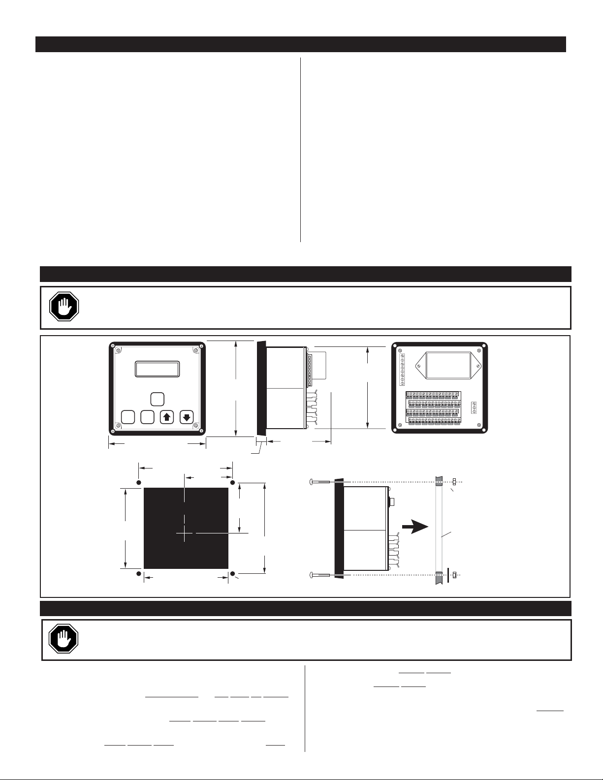
TTDJ MOUNTING DIMENSIONS (All Models)
WARNING: PERFORM THE MOUNTING OPERATION WITH POWER SOURCE OFF. THE TTDJ SERIES MODULE WAS DESIGNED
TO BE MOUNTED WITHIN A WEATHERPROOF ENCLOSURE. IT IS INTENDED FOR MOUNTING IN A FLAT PANEL. A SQUARE
MOUNTING HOLE OF 5-1/2 IN. (140 MM) AND FOUR MOUNTING SCREW HOLES ARE NEEDED. INSERT THE MODULE FROM THE
FRONT SIDE OF THE PANEL AND SECURE THE FOUR MOUNTING SCREWS AND NUTS THROUGH THE BEZEL.
REPLACING THE BATTERY (-IGN Models only)
WARNING: THE BACKUP POWER BATTERY IS LOCATED WITHIN THE TTDJ MODULE. THEREFORE, EXTREME CAUTION MUST BE
EXERCISED WHEN REPLACING IT. FOR CLASS I, DIVISION 2, HAZARDOUS AREAS INSTALLATIONS, FIRST, SHUTDOWN THE SYSTEM
AND MAKE SURE THAT THE HAZARDOUS AREA IS KNOWN TO BE NON-HAZARDOUS BEFORE OPENING THE POWER SUPPLY COVER.
Power Input (Operating Voltages):
TTDJ-DC; TTDJ-DC-T Models:10- 32VDC, 500 mW max.
TTDJ-IGN; TTDJ-IGN-T Models:90-350 VDC negative ground
CD ignition; approx. 650µA @ 100VDC.
Sensor Inputs: 32 N.O. or N.C. passive switches.
Inputs 1-16: Configurable as Class “A”, “B1”, “B2”, or “C” Shutdown or
Alarm Before Shutdown*.
Inputs 17-28: Dedicated Class “A” shutdowns.
Inputs 29: Configurable as Class “A” or Class “ESD”.
Input 30: Selectable Remote Reset or Class “A”.
Input 31: Remote Lockout or Class“A”; inhibits the Class “B1 &
B2” Lockout Timers.
Input 32: Class “ESD” Overrides Test Timer, typically used for emergency
shutdown.
Outputs: 0.5 A @ 350 VDC.
Outputs Selection: Ground ignition immediately or trip fuel valve and ground igni
tion after time delay.
Communications: RS485 Serial Port, Modbus RTU slave (TTDJ-DC models).
Operating Temperature: -40 to 185°F (-40 to 85°C).
Storage Temperature: -40 to 185°F (-40 to 85°C).
Sensor Scan Rate: Within 1 second.
B1 Start/Run Timer: Adjustable, 0 - 5 minutes.
B2 Start/Run Timer: Adjustable, 0 - 9:59 minutes.
Pulses per Revolution Range for Tach. Calibration:
32-360 (TTDJ-DC-T); 1 - 16 (TTDJ-IGN-T).
Overspeed Set point: 0 - 9999 rpm.
Underspeed Set point: 0 - 5000 rpm.
Magnetic Pickup: 5 - 120 Vrms, 0-10 kHz.
On-Board Backup Power 00005125 (-IGN Versions only):
6 VDC, 1300 mAh, Duracell®DL223A or Sanyo®CR-P2 Lithium battery.
Tachometer Accuracy: ±0.5% of the display reading or ±1 RPM
whichever is greater.
Hourmeter Range: 0 to 65535 hrs.
Hourmeter Accuracy: ±15 minutes per year.
SPECIFICATIONS
*
Alarm Before Shutdown is a function that causes annunciation and the alarm output, but will not cause a shutdown.
5-1/4 in.
(133 mm)
Panel Mounting Side View
Keps
Nut
Mounting
Hole
Panel
RESET
6-1/2 in. (165 mm)
5.50 in.
(140 mm)
SENSOR RPM
READ
HOURS
RUN
STOP
6.0 in. (152.3 mm)
Mounting Hole
5.50 in. (140 mm)
3.0 in.
(76 mm)
6-1/2 in.
(165 mm)
49/64 in.
(19 mm)
3.0 in.
(76 mm)
(152 mm)
0.156 in. (4 mm)
dia. 4 places
6.0 in.
3-3/8 in.
(86 mm min. mounting clearence)
Screw
Page 4

TTDJ-99062N page 4 of 8
TYPICAL WIRING DIAGRAMS (All Models)
IGN
GRD
FV+
FVALR
NA
NA
NA
10-32 VDC
Power
supply
Wiring must be kept
separate from ignition leads.
90-350 VDC Capacitive
Discharge Ignition System
Typical Normally
Open Sensors
Typical Normally Closed
Sensor (Remove jumper)
Sensor Input Terminals
NOTES:
1. Sensors are normally open or normally closed
mechanically actuated passive switches
or Murphy
certified, non-incendive or intrinsically safe products
.
2. Non-incendive field circuits–VOC= 10.5 VDC, ISC= 1.2 mA.,
CA= 21 uf, LA= 1000 mH.
3. IGN, FV and Alarm outputs are rated 0.5 A continuous 350 VDC.
4. Power input 90-350 VDC, CD ignition.
5. ALR relay must be hermetically sealed relay,
CSA or UL approved for use in Class I, Div. 2,
Grps C & D hazardous locations.
Sensor leads max. length= 500 ft.
POS
NEG
DIODE
FUEL VALVE
ALARM RELAY
IGN
POS
NEG
User wiring installed per NEC for Class I,
Div. 2, Grps. C & D hazardous locations.
Non-incendive field wiring connections to
passive switches. Route leads separate from
other wiring. Refer to Notes (1,2).
FV
ALR
Power Supply
Cover
RS485
A
SD
GRD
NA
FV
ALR
MPU
GRD
10-32VDC
B
SHD
Power Supply
Cover
12-24 VDC
Power supply
Magnetic Pickup
5 to 120 Vrms
Typical Normally
Open Sensors
Typical Normally
Closed Sensor
(Remove jumper)
Sensor Input Terminals
NOTES:
1. Sensors are normally open or normally closed mechanically
actuated passive switches,
or Murphy, certified, non-incendive
or intrinsically safe products.
2. Non-incendive field circuits–VOC= 10.5 VDC, ISC= 1.2 mA.,
CA= 21 uf, LA= 1000 mH.
3. SD, FV and Alarm outputs are rated 0.5 A continuous 350 VDC.
4. Power supply, power input 10-32 VDC, 16 W max.
6. K1 and K2 must be hermetically sealed relays, CSA or UL approved
for use in Class I, Div. 2, Grps C & D hazardous locations.
7. Fuel Valve in this diagram could be another relay like K1 and K2.
Sensor leads max. length= 500 ft.
+12/24 VDC
-12/24 VDC
K1
ALARM RELAY
IGNITION RELAY
DIODE
–+
–+
K2
User wiring installed per NEC for Class I,
Div. 2, Grps. C & D hazardous locations.
– WARNING –
Explosion hazard.
DO NOT Connect or
disconnect RS485
leads unless
the area is known
to be non hazardous.
Non-incendive field wiring
connections to passive switches.
Route leads separate from other
wiring, refer to Notes 1 and 2.
FUEL VALVE
FV
Alternate hook-up for using latching
48 VDC coil solenoid for alarm air horn.
NOTE: FV– terminal cannot be used
with this hook-up for a CD fuel valve.
SOL
FV+
FV–
ALR
WARNING: FOR HAZARDOUS APPLICATION REQUIREMENTS, THE TTDJ COMPLETE SYSTEM MUST BE INSTALLED
IN ACCORDANCE WITH THE NATIONAL ELECTRICAL CODE (NEC) CLASS I, DIVISION 2, GROUPS C & D (ARTICLE 504)
SPECIFICATIONS AND PER MURPHY DRAWING 50-08-0039. SENSOR INPUT WIRES MUST BE SEPARATED A MINIMUM
OF 2 IN. (51 MM) FROM OTHER WIRES.
TTDJ-DC AND TTDJ-DC-T TYPICAL WIRING
TTDJ-IGN AND
TTDJ-IGN-T TYPICAL WIRING
Page 5

TTDJ-99062N page 5 of 8
RESET
TYPE SETUP
STOP STOP STOP
TTDJ SENSOR SETUP MAP
TIMER "0"
STOP STOP STOP STOP
TIMER "0"
(SETUP)
TEST
STOP
(SETUP)
STOP
STOP
STOP
STOP
Page 6

TTDJ-99062N page 6 of 8
RESET
STOP
STOP
STOP STOP
STOP
STOP
STOP
STOP
STOP
STOP
(SETUP)
TIMER "0"
TEST
STOP
(SETUP)
STOP STOP
TTDJ SETUP MAP
STOP STOP
STOP STOP
STOP STOP
STOP
STOP
STOP
STOP
STOP
STOP
STOP
STOP
STOP
STOP
Page 7

User Set Up Menus
The following are the User Setup Menus for All TTDJ models:
SETUP.1 = Class B1 Timer (0 – 5:00)
SETUP.2 = Class B2 Timer (0 – 9:59)
*SETUP.3 = Sensor 1-16 Type Setup
SETUP.4 = Ignition Ground Delay (0 – 20 sec.)
*SETUP.5 = Remote Setup
0= No Remote Lockout or Reset, #29 is Class “A”
1= Remote Reset, No Remote Lockout, #29 is Class “A”
2= Remote Lockout, No Remote Reset #29 is Class “A”
3= Remote Reset, and Lockout, #29 is Class “A”
4= No Remote Reset or Lockout, #29 is Class “ESD”
5= Remote Reset, No Remote Lockout, #29 is Class “ESD”
6= Remote Lockout, No Remote Reset #29 is Class “ESD”
7= Remote Reset and Lockout, #29 is Class “ESD”
*SETUP.6 = Hours Setup
The User
Setup Menus shown below are also available for -T models:
*SETUP.7 = Pulses per revolution
SETUP.8 = Overspeed
SETUP.9 = Underspeed
The User
Setup Menu shown below is for ALL -DC models:
SETUP.A = Modbus RTU node number 1-16 (-DC models)
*These Set Up Menus are code protected (for all models).
To
Enter User Set
Up Menus
(Must be in Manual Stop #52)
To enter the User
Setup Menus the TTDJ unit Must
be in the Manual
Stop (#52) condition. If a shutdown is present other than Manual Stop,
press the “Reset” key, then immediately Press and Hold Both the
Run/Stop and Up
(Timer 0) keys. Now follow these steps:
1. Press and hold both the Run/Stop and Up (Timer 0) keys until the
LCD reads (HOLD).
2. Continue to hold both keys for 3 more seconds approximately. The
display reads (SETUP.0), you are now in the User
Setup Menu.
3. Use the Up key (Timer 0) and Down (Test) keys to select the desired
Setup Menu.
4. Press the Run/Stop key to enter the desired Setup Menu.
NOTE: Some settings are password protected.
5. Use the Up and Down keys to preset the desired parameter. Press
Reset to zero the value.
6. When the desired value is entered, press Run/Stop.
7. Repeat Steps 3-6 until all parameters are preset.
8. To exit User Setup, select SETUP.0 and press Run/Stop.
Code
Protection
For Setup Menus that are code protected, the LCD will read “CODE.00”
prompting the user to enter a code before allowing setup. Use the Up
and Down keys to enter the code. If the code is entered incorrectly, the
LCD will read “Error”. After 3 incorrect entries, the Code Setup is exited. Once the correct Code is entered, the Setup Menu is accessed.
To Calibrate the Tachometer (TTDJ-DC-T
and TTDJ-IGN-T models)
The TTDJ measures RPM based on the number of pulses per engine revolution. To calibrate the tachometer first enter the User Set Up Menus, see
steps 1-3 from “To
Enter User Set Up Menus” above.
Select SETUP.7. Enter the code, then enter your number of pulses per
engine revolution (refer to Pulses/Revolution
, above right).
Pulses/Revolution
TTDJ-IGN-T (Ignition Model)
For this model the number of pulses per revolution is determined by the number of cylinders and cycles of the engine, according to the following table:
TTDJ-DC-T (DC Model)
For TTDJ-DC-T models the pulses per revolution can come from a magnetic pickup. The number of pulses per revolution is simply the number
of teeth on the flywheel gear (32 to 360).
Sensor Input Set Up
Sensor inputs 1-16 are configurable. The following types are available:
Type 0 = Class A, Shutdown
Type 1 =Class B1, Shutdown
Type 2 =Class B2, Shutdown
Type 3 =Class C, Shutdown
Type 4 = Class A, Alarm Before Shutdown
†
Type 5 = Class B1, Alarm Before Shutdown
†
Type 6 = Class B2, Alarm Before Shutdown
†
Type 7 = Class C, Alarm Before Shutdown
†
To configure a Sensor Input:
1. Enter the SETUP.3 menu (enter the code). The Display will read:
(3 00).
2. Use the Up and Down keys to select the input to be configured.
For example if you select Input #1 the display reads:
(3 01).
3. Press the Run/Stop key. Assuming you selected Input #1, and that
input is currently configured as a Class A, Shutdown, the display
will read (01 0).
4. Use the Up and Down keys to select the desired Sensor Input Type.
5. Press the Run/Stop key, the display reads: (3 01).
6. Repeat Steps 2-5 as necessary.
7. To Exit press Reset, the display shows: (3 00).
Then press the Run/Stop key.
Elapsed Time Set / Reset
Enter the Elapsed
Time Set Up. SETUP.6. First make sure the jumper
for Input #30 is installed. To Set
the time do the following:
1. Enter the SETUP.6 menu (enter the code). The display will read the
elapsed time in hours, after the 6 (for example:
(6.00001) if the elapsed time is 1 hour).
2. Set the desired time using the Up/Down keys. Press Resetto zero the time.
3. When the desired time is entered, press the Run/Stop key.
4. To exit User Setup, press Reset, the display will show:
(SETUP 0) and press the Run/Stop key.
NOTE: Decimal fractional of the elapsed time is lost when the Elapsed
Time Setup is entered, and it can only be set to the nearest hours.
TTDJ USER CONFIGURATION AND SETUP
Cylinders Cycles Pulses
121
222
241
323
424
442
525
Cylinders Cycles Pulses
626
643
828
844
10 4 5
12 4 6
16 4 8
NOTE: Divide the number of cylinders by 2 for split capacitor ignitions.
Multiply the number of cylinders by 2 for throw away spark ignitions.
†
Alarm Before Shutdown is a function that causes annunciation
and the alarm output, but will not cause a shutdown.
TTDJ-99062N page 7 of 8
Page 8

TTDJ-99062N page 8 of 8
System Start Up
Press the RESET key to clear any faulted sensor input and unground/enable
ignition for engine operation. Apply starting power to the engine.
The first thing displayed on versions with Tachometer is the engine speed.
While there is time remaining in either of the Class “B” timers, the display
will alternate between engine speed and the Class “B” timers (4 seconds
each). Once the Class “B1” timer expires, while there is time remaining in
the Class “B2” timer, the display will alternate between the engine speed and
the Class “B2” timer (4 seconds each). Once both Class “B” timers expire,
the engine speed is displayed continuously.
While there is time remaining in the Class “B1” timer, the display will alternate
between engine speed and the Class “B1” time remaining for example: “1 0:30”
(4 seconds each). All sensor inputs configured as Class “B1” are locked out at
this point. For non -T models the “B1” display will be steady. To zero this
timer, press TIMER “0”.
Once the Class “B1” timer expires while there is time remaining in the Class
“B2” timer, the display will alternate between engine speed and the Class “B2”
time remaining for example: “2 0:30” (4 seconds each). All sensor inputs
configured as Class “B2” are locked out at this point. For non -T models the
“B2” display will be steady. To zero this timer press the TIMER “0” key, after
the Class “B2” timer has expired.
To display the run hours, press the “Display Hours” key. The current Run hours will
be displayed for 5 seconds. NOTE: On all non tachometer models (non -T) the
RUN HOURS are displayed after the Class “B” Timers expire, instead of ENGINE
SPEED. The decimal point flashes to indicate the unit is running.
If any one of the sensor inputs configured as an ALARM-ONLY is faulted, the
Alarm Output will turn ON, and the sensor number will be displayed in the first
two digits. Press the RESET key after the sensor input has cleared, to clear the display and to turn OFF the Alarm output.
If the engine speed exceeds the Overspeed Set point the engine will shutdown,
bypassing the Ignition Ground Delay. The TTDJ-T models will display “50”.
Overspeed overrides the Test mode.
If after the Class “B1” Timer expires the engine speed falls below the
Underspeed Setpoint , the engine will shutdown. The TTDJ will
annunciate/display “51”. Underspeed overrides the Test mode.
To manually shutdown the engine, press the STOP/RUN key. The TTDJ will
shutdown the system and the display will indicate “52”. Manual Stop overrides the Test mode.
Upon reaching a shutdown condition, the unit will trip the fuel valve, and, after
the delay expires, ground the ignition. This delay is bypassed on Overspeed
(50), Emergency Shutdown (32), and sensor input #29 if configured as Class
“ESD”.
TTDJ-IGN models annunciate/display “51” when ignition input is lost.
The energy stored in the FV+ circuit will trip the fuel valve.
After the shutdown condition is cleared on the equipment, press RESET key.
The Test Timer is used to verify that sensors are wired properly and working
correctly. To perform a sensor test while running do the following:
1.
Press the TEST key and verify that the Test Timer is shown with
5 minutes: (3 5.00).
2.
Trip the first sensor to be tested and verify that the sensor number and
class type appear on the display (see displays below). The display will
alternate between the Sensor Number and the Test timer.
3.
Clear the sensor then press the RESET key. Verify that the sensor number is cleared from the display.
4.
Repeat Steps 2 and 3 for each sensor.
5.
To exit, press the TIMER “0” key or allow the Test Timer to expire.
NOTE: Any of the following conditions will override the Test Timer:
Emergency Shutdown (32), Overspeed Shutdown (50), Underspeed Shutdown
-T models (51), Loss of Ignition (51) non-T models, Manual Stop (52), and
sensor input #29, if configured as a Class “ESD”..
In Test, when a sensor is tripped, he sensor number and the Class type are
displayed, for example if sensor #1 (01) a Class “B1” shutdown is tripped in
the Test the LCD reads “01 t1”. The following are the Test Mode Displays:
(t0): Class “A” Shutdown
(t1): Class “B1” Shutdown
(t2): Class “B2” Shutdown
(t3): Class “C” Shutdown
(t4): Class “A” Alarm
(t5): Class “B1” Alarm
(t6): Class “B2” Alarm
(t7): Class “C” Alarm
SEQUENCE OF OPERATIONS
A limited warranty on materials and workmanship is given with this
FWMurphy product.
A copy of the warranty may be viewed or printed by going to www.fwmurphy.com/warranty.asp.
R
E
G
I
S
T
E
R
E
D
USA–ISO 9001:2000 FM 28221
UK–ISO 9001:2000 FM 29422
Printed in U.S.A.
M
ur
C
al
c
CALL MURCAL TO PLACE YOUR ORDER
P: (6 61 )2 72 -4 70 0 F: (6 61 )9 47 -7 57 0
w w w. m u r c a l . c o m e - m a i l : s a l e s @ m u r c a l . c o m
Engine Speed (-T Models Only)
Class “B1” Timer
Class “B2” Timer
Elapsed Time
Alarm Only Condition
Overspeed (-T Models Only)
Underspeed (-T Models Only)
Manual Stop
Ignition Ground Delay
Loss of Ignition
Resetting Shutdown Fault
Test Timer
Test Mode Display
Warranty
 Loading...