

Page 1
TSM-95129N
®
FRANK W.
MFR.
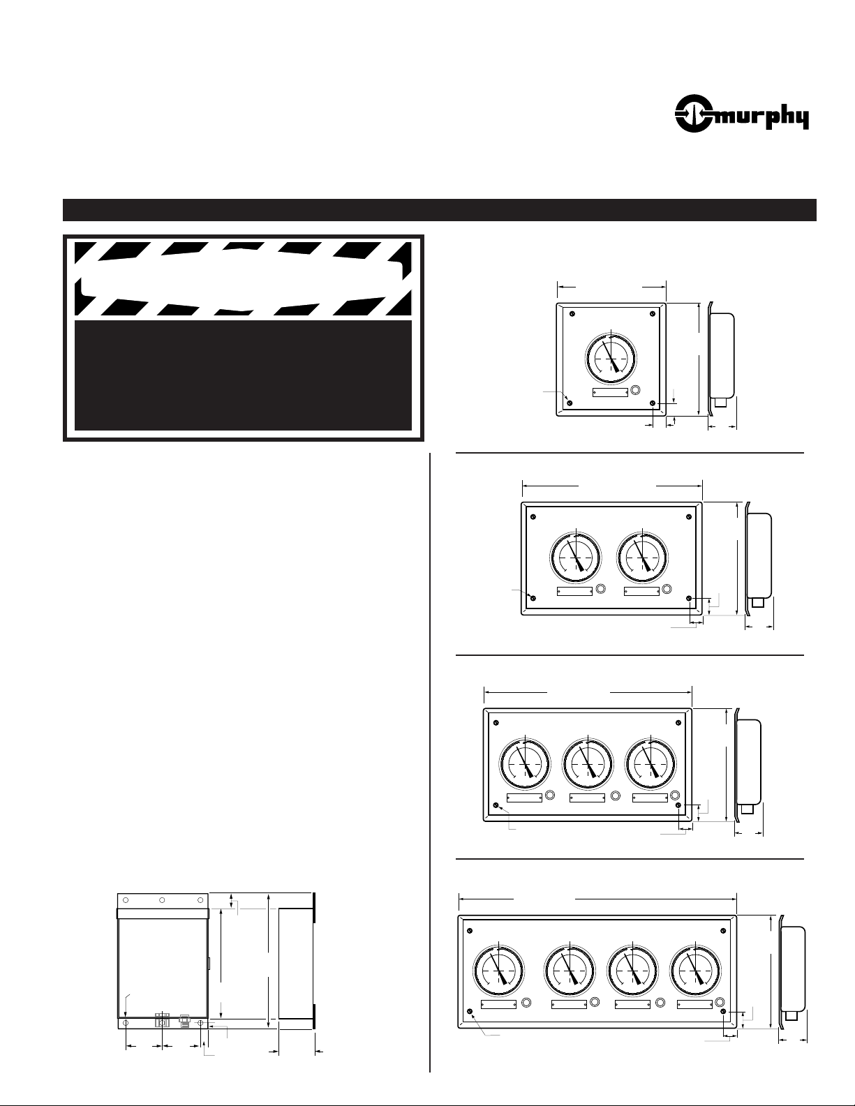
1-1/2 in. (38 mm)
1/4 in.
(6 mm) dia.
4-places
Mounting Holes
1-1/2 in.
(38 mm)
14 in. (355 mm)
14 in.
(355 mm)
3 in.
(76 mm)
1/4 in.
(6 mm) dia.
4-places
Mounting Holes
25-3/8 in. (645 mm)
14 in.
(355 mm)
3 in.
(76 mm)
1-3/16 in.
(30 mm)
2-1/2 in.
(63 mm)
12-1/4 in.
(311 mm)
1-1/4 in.
(32 mm)
9/32 in.
(7 mm) dia.
6-places
10 in.
(254 mm)
5/8 in.
(16 mm)
4-1/8 in.
(105 mm)
3 in.
(76 mm)
3 in.
(76 mm)
36 in. (914 mm)
1/4 in. (6 mm) dia.
4-places–Mounting Holes
14 in.
(355 mm)
3 in.
(76 mm)
1-3/16 in.
(30 mm)
2-1/2 in.
(63 mm)
14 in.
(355 mm)
3 in.
(76 mm)
1-3/16 in.
(30 mm)
2-1/2 in.
(63 mm)
39-1/2 in. (1 m)
1/4 in. (6 mm) dia.
4-places–Mounting Holes
Revised 01-97
SM Series TANKTENDTMSystems
Section 15
(00-02-2019)
Installation and Operation Instructions
Models: SM1, SM1VR, SM2, SM2VR, SM3, SM3VR, SM4, SM4VR
Please read the following information before installing. A visual inspection of this product for damage during shipping is recommended
before mounting. It is your responsibility to have a qualified person install this unit and make sure it conforms to NEC and local codes.
GENERAL INFORMATION
Mounting Dimensions
SM1 / SM1VR (1-Tank Monitoring Systems)
WARNING
BEFORE BEGINNING INSTALLATION OF THIS MURPHY PRODUCT
✔ Disconnect all electrical power to the machine.
✔ Make sure the machine cannot operate during installation.
✔ Follow all safety warnings of the machine manufacturer.
✔ Read and follow all installation instructions.
The SM Series System
can monitor above or below ground,
single or multi-tank systems (4 tanks maximum). The SM Series
includes BGT1 gage (s) in a wall mounting panel. The SMVR series
includes a vapor recovery option that compensates for gas blankets or
head pressure caused by vapor recovery storage systems.
The SM includes a push-button actuated electrical pump assembly, that
supplies the air to clear sensing lines for current readings. Pump operating voltages available are 120 or 230 VAC (see below).
SM Series Specifications
Panel: Hollow wall mount, cold rolled steel, painted.
Shipping Weight (P100 Pump included):
SM1: 27 lb. (12.25 kg) approximately.
SM2: 44 lb. (20 kg) approx.
SM3: 54 lb. (24.5 kg) approx.
SM4: 65 lb. (29.5 kg) approx.
Shipping Dimensions for All Models (P100 Pump included):
40 x 9 x 15-3/4 in. (1016 x 229 x 400 mm).
SMPA and SMPA230 Pump Assemblies
Operating Voltage: 120 VAC (SMPA); 230 VAC (SMPA230).
2
Power Cable: Insulated, 16 AWG (1.5 mm
) x 8 ft. (2.4 m).
Case: Weatherproof enclosure; painted.
Shipping Weight: 10 lbs. (4.53 kg).
Shipping Dimensions: 12 x 12 x 10 in. (305 x 305 x 254 mm).
SM2 / SM2VR
SM3 / SM3VR
(2-Tank Monitoring Systems)
(3-Tank Monitoring Systems)
*
*
SMPA and SMPA230 Mounting Dimensions
SM4 / SM4VR
(4-Tank Monitoring Systems)
*
* Mounting dimensions also apply for vertical mounting configurations.
Page 2

INSTALLATION
A
B
C
D
E
F
G
Steel Tube Located
3 in. (76 mm) Off
Bottom (typical)
A. Manwell
B. Driveway Surface
C. UTKN Tank Plug
D. Coupling
E. Stand-Pipe
F. Tank Plug Opening
G. 1/4 in. (6 mm) dia. Steel Tube
Product
SM1 Model
Below ground
tank (vented)
Tubing
To Pump
Assembly
FEET
MURPHY
LEVELGAGE
A
B
C
D
E
F
G
H
Steel Tube Located
3 in. (76 mm) Off
Bottom (typical)
A. Manwell
B. Driveway Surface
C. UTKN Tank Plug
D. Coupling
E. Stand-Pipe
F. Tank Plug Opening
G. 1/4 in. (6 mm) dia. Steel Tube
H. Vapor Recovery Line
Product
Below ground
tank (vented)
Keep tip of
line above
product level
Vapor Recovery
Tubing
Tubing
SM1 Model
To Pump
Assembly
FEET
MURPHY
LEVELGAGE
UTKN Tank Plug
or tank top
1/2 in. (13 mm)
Ferrule
Tubing
Tubing Fitting
(2 included)
Compression
Nut
Hole Plug
1/4 in. (6 mm) dia.
304 Stainless Steel
tubing (probe);
12 ft. (3.6 m) long
Compression
Nut
Ferrule
Hole Plug
Sensor Fitting
UTKN
Tank Plug
Vapor Recovery
connection (plugged)
Tubing
Connection
1/4 x 12 ft. (3.6 m)
Steel Tubing
WARNING: Installation of the SM and SMVR Series MUST BE made by qualified installer. Hazardous conditions exist with flam-
mable and corrosive products. Extinguish all smoking materials. Risk of explosion, fire and burning can cause serious or fatal injury.
Installing a Tank Plug Kit (all models)
The tank plug kit includes 12 ft. (3.6 m) x 1/4 in.
(6 mm) dia. stainless steel tube and fittings.
Tank plug is available in 2 NPT or 4 NPT.
1.
Locate tank(s) service cover and install
a UTKN tank plug kit for each tank.
Necessary hardware is available from
Murphy, refer to “Service Parts and
Accessories” section, on page 4.
2.
Route a tubing line (1/4 in. [6 mm] outside dimension) from the tank top to the
panel location. If applicable, cut a channel in the
driveway surface to route the tubing. The use of rigid conduit is recommended especially when routing the tubing line under a driveway surface.
Refer to Fig. 1, at right.
3.
Before inserting the 1/4 in. (6 mm) dia.
stainless steel tubing (probe) through tank
plug fitting, make sure tubing can reach
bottom and also will allow extra tubing for adjustments. Now lower the
tubing until it touches the bottom
of the tank, do this as follows
(refer to Detail A, at right):
A. First, loosen ferrule and ferrule
fitting nut.
B. Insert the tubing through the
ferrule nut and fitting.
C. Mark tubing at top of fitting–raise tub-
ing exactly 3 in. (76 mm) off bottom and
finger tighten ferrule and compression nut.
Tank Plug
Detail A
Fig. 1
Fig. 2
SM Series Typical Installation
SMVR Series (Vapor Recovery Systems)
typical Installation
D. Cut excess stainless steel tubing allowing 1/2 in. (13 mm) extension
4.
Connect tubing line to tank probe as shown
(refer to Detail B, at right).
5.
Now connect other end of tubing line
to the SM/SMVR gage panel fitting. Tubing should be continuous
length without splices.
6.
For SMVR models, connect a
second line from the tank top (if
using UTKN kit, remove Hole
Plug and install second sensor fitting and line) to the SMVR gage 1/8
NPTF fitting line. Second sensing line
is to be installed through the tank top and
into the tank, but keep the tip of the line above
product level (refer to Fig. 2, at right and Fig. 3, next page).
7.
Securely tighten all fittings; all connections must be air tight.
2
prohibit re-adjustment if necessary.
above the compression nut.
CAUTION:
Excessive tightening of ferrule fittings will
Detail B
Page 3

INSTALLATION
To Tank 1 Plug
Sensor Fitting
To Tank 2 Plug
Sensor Fitting
SM Panel (SM2 Model Shown)
To Tank 1 Plug
Vapor Recovery
Fitting
To Tank 2 Plug
Vapor Recovery
Fitting
To Pump
Assembly
FEET
MURPHY
LEVELGAGE
FEET
MURPHY
LEVELGAGE
120 VAC or 230 VAC
Tubing to SM Panel
Pressure SWICHGAGE
®
kPa
PRESSURE
0
100
20
40
60
0
300
80
600
PSI
M
U
R
P
H
Y
S
W
I
C
H
G
A
G
E
®
Low trip point
adjustment
High trip point
adjustment
Tubing
Power
Cable
Compression
Nut
Ferrule
Sensor Fitting
Pump
Panel
Turn to Lower
the Pointer
Turn to Raise
the Pointer
Tubing
Check
Valve
Valve
Flat
1/4 NPTM
straight
fitting
1/4 NPTM
straight fitting
Ferrule
Ferrule nut
1/2 NPTM to
1/4 NPTF
Reducer
UTKN Tank Plug
or tank top
Hole Plug
T
A
N
K
Continued
Installing the CKBO Check Valve
The optional CKBO check valve is designed
to prevent product from backing up into the
Detail C
Fig. 3
gage(s). We recommend installing the
CKBO valve at top of the tank plug as
follows (refer to Detail C):
1.
Determine a location for the valve.
Use of sealant on all fitting
threads is strongly suggested.
2.
Attach CKBO to the tank plug
using wrench on valve flats.
See markings on the valve body
for positioning.
3.
Attach tubing to CKBO as shown.
Securely tighten all fittings.
All connections must be air tight.
Installing the SMPA /SMPA230 Pump Assembly
The pump assembly should be installed near the SM or SMVR panel.
Connect the pump as follows (refer to Fig. 3 and 4 also see Detail D):
1.
Before connecting the tubing from the SM or
SMVR panel to the pump assembly, make sure
the tubing reaches the pump assembly
sensor fitting.
2.
Connect the end of the tubing to the sen-
sor fitting as shown at right (Detail D).
Tubing should be continuous length
without splices.
3.
The pump assembly includes a power
cable, 16 AWG (1.5 mm2), 8 ft. (2.4 m)
long. Connect the cable to 120 VAC or
230 VAC power source.
The pump assembly has a pressure SWICHGAGE
with low and high pressure set points. When the gage pointer reaches the
low pressure set point, the pump starts to built up purge pressure. When the
pointer reaches the high set point, sufficient volume is reached stopping the
pump. The set points are factory pre-set for your convenience.
Detail D
Fig. 4
®
SM Panel Tubing Configuration
(SM2 Model shown)
Pump Assembly
Resetting the Pointer
After the SM/SMVR complete system has been connected, reset the pointer
for proper level indication, proceed as follows
(see Fig. 5 and Detail E):
1.
2.
3.
4.
5.
CAUTION:
SM and SMVR models are precalibrated in feet of
static pressure above gage connection. Pointer MUST be reset to zero.
Detail E
Determine actual product level by any reliable
means and record this value.
Very carefully remove the retaining ring
guarding against its spring-action, it can
cause injuries. Remove the lens also.
Carefully hold the pointer, as shown at
right, making sure not to bend it.
With a small screwdriver, turn the setting
screw to corresponding stick reading value
recorded in step 1.
Clockwise to raise the pointer — counter clockwise to lower the pointer.
Replace the lens and snap ring.
Fig. 5
SM Panel (SM2 Model Shown)
Snap Ring
Pointer
FEET
MURPHY
LEVELGAGE
Read Button
UNLEADED UNLEADED
FEET
MURPHY
LEVELGAGE
3
Page 4

INSTALLATION
®
FRANK W.
MFR.
Continued
Operation Sequence
IMPORTANT:
installed and operative. Check that all connections are air tight.
1.
Make sure that the pump assembly is connected to a power source,
either 120 VAC or 230 VAC according to the pump model used.
2.
Depress the read button, located next to the gage(s) and hold until the
gage pointer stops traveling across the scale. See Fig. 6, at right.
3.
When pointer stops release the read button to allow pointer to settle.
4.
The value observed in the dial of the gage, is the level of the tank.
5.
Perform this operation as necessary for each tank to be checked.
Make sure SM Series system is completely
Service Parts and Accessories
UTKN2:
UTKN2LT:
UTKN4:
UTKN4LT:
UTKN4VR:
UTKN4VRLT:
SMPA:
SMPA230:
05090051:
CKBO:
85-01-0405:
85-01-0402:
85-01-0403:
86-03-0405:
85-03-0407:
2 NPTM tank plug kit (includes 12 ft. [3.66 m] of stainless steel tubing/probe and fittings).
2 NPTM tank plug less tubing (includes fittings).
4 NPTM tank plug kit (includes 12 ft. [3.66 m] of stainless steel tubing/probe and fittings).
4 NPTM tank plug less tubing (includes fittings).
4 NPTM tank kit for vapor recovery (tubing and fittings included).
4 NPTM tank plug for vapor recovery– less tubing (includes fittings).
Pump assembly for 120 VAC.
Pump assembly for 230 VAC.
Pressure SWICHGAGE®instrument with low and high pressure limit contacts, 15 psi scale.
Check Valve assembly–prevents product from backing up into gage.
1/2 NPTM x 1/4 NPTF reducing bushing–for CKBO valve mounting.
1/4 in. (6 mm) dia. 316 stainless steel tubing/ft. (probe).
1/4 in. (6 mm) dia. poly tubing/ft. (sensing line).
1/4 x 1/4 male hex nipple kit–for connecting tubing line to tank top.
1/4 x 1/4 male hex fitting kit–for connecting tubing or probe line to the tank top.
Fig. 6
SM Panel (SM2 Model Shown)
Snap Ring
Pointer
FEET
MURPHY
LEVELGAGE
Read Button
UNLEADED UNLEADED
FEET
MURPHY
LEVELGAGE
Warranty
A two year limited warranty on materials and workmanship is provided with this Murphy product.
Details are available on request and are packed with each unit.
In order to consistently bring you the highest quality, full featured products, we reserve the right to change our specifications and designs at any time.
■ Murphy de México, S.A. de C.V.
Blvd. Antonio Rocha Cordero 300, Fracción del Aguaje
San Luis Potosí, S.L.P.; México 78384
tel. +52-48-206264 fax +52-48-206336
e-mail murmexsl@sanluis.podernet.com.mx
■ Murphy Switch of California
P.O. Box 900788; Palmdale, California 93590; USA
tel. (805) 272-4700 fax (805) 947-7570
e-mail sales@murphyswitch.com
■ Frank W. Murphy France
tel. +33 1 30 762626 fax +33 1 30 763989
Since 1939
■ Frank W. Murphy Manufacturer
P.O. Box 470248; Tulsa, Oklahoma 74147; USA
tel. (918) 627-3550 fax (918) 664-6146
e-mail fwmurphy@ionet.net
■ Frank W. Murphy Southern Division
P.O. Box 1819; Rosenberg, Texas 77471; USA
tel. (281) 342-0297 fax (281) 341-6006
e-mail murphysd@intertex.net
Printed in U.S.A.
4
■ Frank W. Murphy, Ltd.
Church Rd.; Laverstock, Salisbury SP1 1QZ; U.K.
tel. +44 1722 410055 fax +44 1722 410088 tlx 477088
e-mail sales@fwmurphy.co.uk
■ Frank W. Murphy Pte., Ltd.
26 Siglap Drive; Republic of Singapore 456153
tel. +65 241-3166 fax +65 241-8382
e-mail fwmsales@fwmurphy.com.sg
■ Murphek Pty., Ltd.
1620 Hume Highway; Campbellfield, Vic 3061; Australia
tel. +61 3 9358-5555 fax +61 3 9358-5558
 Loading...