

Page 1
RPS-00092B page 1 of 4
MODEL & PART NUMBERS: DC SOLENOIDS & ACCESSORIES SHIPPING WEIGHT
Model No. Description ozs (kg)
RP2307B 12 VDC, 1 in. (25 mm) stroke, 11 lbf (49 N) pull, 23 lbf (102 N) hold 24 ozs (0.7 kg)
RP2308B 24 VDC, 1 in. (25 mm) stroke, 11 lbf (49 N) pull, 23 lbf (102 N) hold 24 ozs (0.7 kg)
RP2309B 12 VDC, 1-1/2 in. (38 mm) stroke, 14 lbf (62 N) pull, 34 lbf (151 N) hold 48 ozs (1.4 kg)
RP2310B 24VDC, 1-1/2 in. (38 mm) stroke, 14 lbf (62 N) pull, 34 lbf (151 N) hold 48 ozs (1.4 kg)
65-01-0108 Clevis yoke assembly 1 ozs (.03 kg)
65-01-0110 Clevis yoke chain assembly 2 ozs (.04 kg)
40-05-0315 Threaded rod (1-1/2 in.) .05 ozs (.001 kg)
00-00-2457 RPS in-line ball joint .05 ozs (.001 kg)
00-00-2458 RPS 90° ball joint 1 ozs (.03 kg)
RP Series
■
One Solenoid For Pull/Push Operation
■
No Internal Switches
■
Reduce Coil Burnout
■
Boost Reliability
■
Reduce Adjustments
■
High Force–Small Size
■
Can Be Used With Most Engines
Start Systems
■
SD85 Solenoid Drive Time Delay
Available To Greatly Reduce Possibility
Of Coil Burnout And Facilitate Low
Current Piloted Operation.
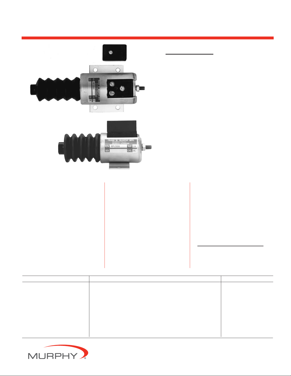
RP2307B & RP2308B
RP2309B & RP2310B
RPS-00092B
Revised 11-03
Catalog Section 40
(00-02-0107)
Pull/Push DC Solenoids for
Diesel Engines
Description
Murphy push/pull DC Solenoids
provide single unit versatility for engine
applications, such as shutdown.
A choice of two models and two
voltages is available. All models come
complete with return spring and rubber
seal boot. See the next page for
specifications and options.
Basic Models
Models RP2307B and RP2308B give a
full one inch (25 mm) stroke at 11
pounds (49 N) and hold up to 23 pounds
(102 N) at full voltage, continuous duty.
They will operate at any stroke less than
maximum; refer to the chart shown on
page 2.
Models RP2309B and RP2310B can
pull 14 pounds (62 N) with a one-and-ahalf inch (38 mm) stroke. They hold up
to 34 pounds (151 N) at full voltage,
continuous duty. See the chart on page 2
for holding force at any stroke less than
maximum.
SD85 Solenoid Drive
Time Delay
Using the SD85 ensures the energize
coil is only powered for 1-2 seconds
with each operation. If the plunger does
not seat in that time, it is highly
unlikely it will seat. The hold coil is
energized as long as the signal to the
SD85 is active. This insures long life of
the RP solenoid.
Warranty
A limited warranty on materials and workmanship
is given with this FW Murphy product. A copy of
the warranty may be viewed or printed by going
to www
.fwmurphy.com/support/warranty.htm
Page 2
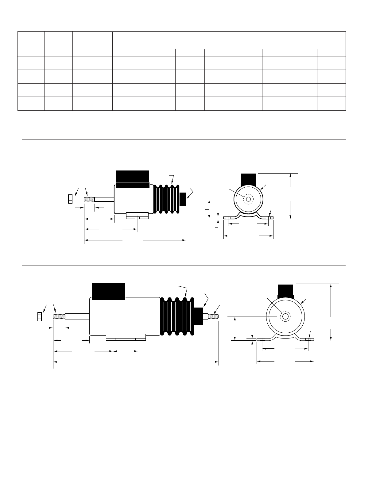
RP2307B and RP2308B
RP2309B and RP2310B
Solenoid Dimensions
Solenoid Shown with Plunger Seated (Coil Energized)
Solenoid Shown with Plunger Seated (Coil Energized)
†
A stud with nut is supplied, loose.
1-1/2 in. (38 mm)—1/4-28
part number: 40-01-0055
Solenoid
Model
Number
Maximum
Stroke
In. (mm)
Power in Watts
Seated Inrush
Force* in Pounds [Kilograms] at 100% Voltage**
Stroke in Inches (Millimeters)
Hold 1/8(3) 1/4(6) 1/2(13) 3/4(19) 1 (25) 1-1/4 (32) 1-1/2 (38)
Continuous
RP2307B 1 (25) 18 624
25 [11.34] 22 [9.98] 21 [9.53] 17 [7.71] 14 [6.35] 10 [4.54] — —
<13> [5.90] <12> [5.44] <11> [4.99] <10> [4.54] <8> [3.63] <6> [2.72] — —
RP2308B 1 (25) 12 696
27 [12.25] 25 [11.34] 23 [10.43] 19 [8.62] 15 [6.80] 11 [4.99] — —
<15> [6.80] <14> [6.35] <13> [5.90] <12> [5.44] <9> [4.08] <7> [3.18] — —
RP2309B 1-1/2 (38) 18 1029
32 [14.52] 30 [13.61] 27 [12.25] 22 [9.98] 18 [8.16] 13 [5.90] 8 [3.63] 6 [2.72]
<19> [8.62] <18> [8.16] <16> [7.26] <14> [6.35] <11> [4.99] <9> [4.08] <6> [2.72] <4> [1.81]
RP2310B 1-1/2 (38) 12 960
35 [15.88] 34 [15.42] 31 [14.06] 26 [11.79] 22 [9.98] 17 [7.71] 12 [5.44] 7 [3.18]
<20> [9.07] <19> [8.62] <17> [7.71] <15> [6.80] <12> [5.44] <9> [4.08] <7> [3.18] <4> [1.81]
*Forces shown are without return spring. Forces shown < > are with return spring. Forces shown in [ ] are in kilograms.
**To determine the operating current, divide the power (watts) indicated in the above table by the applied voltage.
Solenoids will operate at any stroke less than maximum.
†
A stud with nut is supplied, loose.
1-1/2 in. (38 mm)—1/4-28
part number: 40-01-0055
Watts Power/Cold Force in Pounds at 100% Voltage/Inches Stroke
RPS-00092B page 2 of 4
Note 1. Typical operating temperature for single 15 second operation of the energize coil is less than:
140°F(60°C) ± 10°F (6°C) for 1 in. (25 mm) Stroke Solenoids (70°F/21°C Rise above ambient)
120°F(49°C) ± 10°F (6°C) 1-1/2 in. (38 mm) Stroke Solenoids (50°F/10°C Rise above ambient)
See CAUTION statement on next page and note maximum housing temperature is 185°F (85°C).
Note 2. The energize-coil should not be activated for more than 15 seconds.
Longer energize-coil activation times will damage the solenoid.
Note 3. Allow minimum 15 minutes for cooling between activations of energize-coil to avoid damaging the
solenoid. (Depends on length of time energize coil is energized.)
Note 4. The energize-coil must fully seat the plunger to allow the hold-coil to function properly.
1/4-28 Shaft w/nut
shown installed
(is supplied loose)
1/2 in.
(13 mm)
1-19/32 in.
(40 mm)
2-13/16 in.
(72 mm)
5 in.
(127 mm)
Boot
Internal
1/4-28
(25 mm)
†
1 in.
3/32 in.
(2 mm)
NOTE: Remove
or pierce decal
to install shaft.
2 in.
(51 mm)
2-1/2 in.
(64 mm)
1-5/8 in.
Diameter
2-7/16 in.
(62 mm)
9/32 in.
(7 mm)
1/4-28 Shaft w/nut
shown installed
(is supplied loose)
21/32 in.
(17 mm)
2-1/16 in.
(52 mm)
3-9/32 in.
(83 mm)
1-1/2 in.
(38 mm)
7-7/32 in.
(184 mm)
Boot
Internal
1/4-28
†
Shown with
stud and nut
installed.
1-1/8 in.
(28 mm)
Remove or
pierce decal
to install shaft.
3/32 in.
(2 mm)
2 in.
(51 mm)
Diameter
9/32 in.
(7 mm)
2-1/2 in.
(64 mm)
3-1/8 in.
(79 mm)
2-7/8 in.
(73 mm)
Page 3

RPS-00092B page 3 of 4
Mechanical Installation
1. Bolt the solenoid securely to the mounting bracket.
2. Connect linkage and check for binding. Plunger should move
freely throughout the complete stroke and be allowed to
“bottom” at the internal stop of the solenoid.
DO NOT MOUNT WITH BOOT DOWN.
DO NOT APPLY ANY GREASE OR LUBRICATION TO PARTS.
IMPORTANT: If the plunger does not seat, it will release
prematurely when shifted to the “holding” mode of operation.
Readjust linkage to lengthen the plunger stroke. Adjust the yoke
in increments of 1/2 turn until plunger will remain in hold
position.
Electrical Installation
1. Refer to the diagrams above for typical electric wiring.
2. Use minimum 10 AWG [65/0.3 mm (4.5 mm)] wire size, as
noted in the wiring diagrams. A smaller wire will reduce the
current available and thus the pulling force. Wire length must
be kept to a minimum.
Operation
The solenoid coil is connected to the existing engine starter
system or an equivalent circuit. A SD85 is recommended. At
starting, both the Energize and Hold-in coils are energized. In
the run mode, the Hold-in coil is continuously energized while
the Energize coil has to be disconnected, reducing the heating
effect and power consumption and avoiding damage to the
device.
NOTE: Coils that burn out due to improper electrical hookup,
misadjustment or improper operation are not covered by Murphy
factory warranty.
NOTE: A cool down period of 15 minutes minimum should be
allowed between energized pull in cycles.
*Wires must be minimum 10 AWG (65/0.3 mm [4.5 mm]) to develop full force.
*Wires must be minimum 10 AWG (65/0.3 mm [4.5 mm]) to develop full force.
Typical Wiring Diagrams
CAUTION: The solenoid housing is hot to the
touch. A temperature rise to 185°F (85°C) is
permissible.
Typical time-delayed shutdown using a 760A magnetic switch
(SD85 is optional)
NOTE: In either application if the starter
hangs, on starters with integral solenoids, the
energize coil remains energized.
CAUTION: On certain starter solenoids/contactor relays,
current can feed back through the energize terminal
from the hold coil and provide a parallel path to ground
through the device connected to the energize terminal.
Typical time-delayed shutdown using a 518PH magnetic switch
(SD85 is optional)
20P-F 20T-F
®
SWICHGAGE
Instruments
Typical Closed Loop™ Circuit
Emergency
Stop
TATTLETALE
G NC
518PH
®
SW
SW
B
1
2
In-Line
Fuse
Existing
Start
System
OFF
ON
Turn OFF for
Emergency Stop
IG
Start Key
Switch
B
ST
*
10 AWG
Starter
Motor
12345
10 AWG
ON OFF
Fuel Lever
12345
SD85
10 AWG
SD85
*
*
N.O.
Starter Contactor
Relay
N.O.
10 AWG
10 AWG
*
Energize
*
Hold
Battery
RP2300 Series
Solenoid
Battery
Key Switch
OFF: No power.
ON: Power to hold coil of
fuel solenoid.
START: Power to energize
coil of fuel solenoid.
20P
SWICHGAGE
Instruments
START
20T
®
760A
Time-Delay
Before Shutdown
NO BNC
SG
Starter
Starter Contactor
Relay
10 AWG
10 AWG
*
*
Energize
Hold
Motor
RP2300 Series
Solenoid
*
10 AWG
ON OFF
Fuel Lever
Page 4

RPS-00092B page 4 of 4
RPS Linkage Parts and Assemblies
Threaded Rod
(40-05-0315)
RPS 90° Ball Joint
(00-00-2458)
RPS In-Line Ball Joint (00-00-2457)
SD85: Solenoid Drive Time Delay
The SD85 is used when the solenoid is duty cycled for short time
periods such as 2-position throttle operation. It also provides
enhanced operational control for normal on-off applications. The
SD85 activates both coils of the solenoid for a short time then deenergizes the Energize-coil. The Hold-in coil remains energized.
SD85: Specifications
Input Voltage 8 to 30 VDC
Current Ratings:
40 ma standby (quiescent) 8 to 30 VDC
75 Amps Pull-in @12 VDC
1 Amps Hold @ 12 VDC
37.5 Amps Pull-in @ 24 VDC
0.5 Amps Hold @ 24 VDC
Terminal #3 2 Amps Maximum
Terminal #5 112.5 Amps Maximum during Pull-in
Control
Switch
(continuous HOLD
power to #2 and
temporary PULL
power to #4)
SD85 Terminal Block
Clevis Yoke Bead Chain Assemblies
65-01-0110
12 inch
(300 mm)
Chain
7/8 in.
(22 mm)
5/8 in.
(16 mm)
2 in.
(51 mm)
1/16 x 3/8
Cotter Pin
1/16 in.
(2 mm)
diameter
1/4-28
Thread
1/4 in. (6 mm) diameter
Clevis Yoke
Clevis Yoke Assembly
65-01-0108
Accessories
2-3/16 in.
(56 mm)
2-1/4 in.
(57 mm)
2-1/2 in. (64 mm)
Mounting Holes
3 in. (76 mm)
Mounting Holes
3/16 in. (5 mm)
diameter 2-places
NOTE: Wires designated 10 ga. must be
at least 10 AWG [65/0.3 mm (4.5 mm)] to
develop full force.
CONTROL SYSTEMS & SERVICES DIVISION
P.O. Box 1819; Rosenberg, Texas 77471; USA
+1 281 633 4500 fax +1 281 633 4588
e-mail sales@fwmurphy.com
MURPHY DE MEXICO, S.A. DE C.V.
Blvd. Antonio Rocha Cordero 300, Fracción del Aguaje
San Luis Potosí, S.L.P.; México 78384
+52 444 8206264 fax +52 444 8206336
Villahermosa Office +52 993 3162117
e-mail ventas@murphymex.com.mx
www.murphymex.com.mx
FRANK W. MURPHY, LTD.
Church Rd.; Laverstock, Salisbury SP1 1QZ; U.K.
+44 1722 410055 fax +44 1722 410088
e-mail sales@fwmurphy.co.uk
www.fwmurphy.co.uk
MURPHY SWITCH OF CALIFORNIA
41343 12th Street West
Palmdale, California 93551-1442; USA
+1 661 272 4700 fax +1 661 947 7570
e-mail sales@murphyswitch.com
www.murphyswitch.com
In order to consistently bring you the highest quality, full featured products, we reserve the right to change our specifications and designs at any time.
MACQUARRIE CORPORATION
1620 Hume Highway
Campbellfield, Vic 3061; Australia
+61 3 9358 5555 fax +61 3 9358 5558
e-mail murphy@macquarrie.com.au
FW Murphy
P.O. Box 470248
Tulsa, Oklahoma 74147 USA
+1 918 317 4100
fax +1 918 317 4266
e-mail sales@fwmurphy.com
www.fwmurphy.com
R
E
G
I
S
T
E
R
E
D
USA–ISO 9001:2000 FM 28221
UK–ISO 9001:2000 FM 29422
Printed in U.S.A.
1-1/2 in.
3/8 in.
(9 mm)
3/8 in.
(9 mm)
(38 mm)
1/4-28 Threads
1/4-28
Threads
1-1/4 in.
(32 mm)
2 in.
(51 mm)
1/4-28 Threads
1-1/4 in.
(32 mm)
10 ga.
Ground
Solenoid
Hold
1 2 3
10 ga.
Energize
10 ga.
12-24 VDC
4 5
NC
B
10 ga.
TATTLETALE®
Option
 Loading...