

Page 1
Description
The ASM160 is an engine controller with automatic start/stop, and selectable
warmup/cooldown or glowplug capabilities.
The ASM160 operates from a 12 or 24 volt battery. It includes crank and rest
cycles, sensing circuit for crank disconnect and overspeed, overcrank, and recrank protection on false starts. Four LEDs indicate first-out shutdown for:
Low Oil Pressure, High Temperature, Overcrank, Overspeed. Afifth LED
indicates Engine Running. There are also two (2) spare inputs that will cause
the unit to shut down without annunciation on the front LED’s.
Specifications
Power Input: 12 or 24 VDC.
Operating Temperature: -40 to 185°F (-40 to +85°C).
Inputs: Ground or positive inputs for High Temperature, Low Pressure, and
two spares.
Lamp and Output Test: One ground only input for lamp and output test.
Outputs: 5 Arelay for cranking and fuel valve. 300 mAtransistor for fault
annunciation, warmup/cooldown, or glowplug.
Cycle Crank Timer: Selectable to 3, 5, 10 or infinite attempts.
Crank/Rest Cycle Timing: Crank time 10 seconds. Rest time 15 seconds.
Glow Plug Time Delay: Field adjustable from 1 to 300 seconds.
Warmup T ime Delay: Field adjustable from 1 to 300 seconds.
Cooldown Time Delay: Field adjustable from 1 to 300 seconds.
Shutdown Lockout Time Delay: 15 second lockout for low oil,
high temperature, one spare and loss of speed shutdown on start-up.
Crank Disconnect Speed Setting: Field adjustable from 30 to 8500 Hz.
Overspeed Trip Point Setting: Field adjustable from 30 to 8500 Hz.
Magnetic Pickup Input: Requires 3V rms minimum 30 to 100 Hz;
Requires 2V rms minimum 100 Hz and up; Maximum 35V rms.
Installation Accessories
●
Tools as needed for module mounting, such as drill and screw driver.
●
12 and 14 AWG (4.0 mm2and 2.5 mm2) wire for hook up.
●
Set of wire termination tools.
●
Wire termination; such as spade terminals.
ASM160 MURPHYMATIC®Micro-controller
Installation and Operation Instructions
Please read the following information before installing. A visual inspection of this product for damage
from shipping is recommended before installing. It is your responsibility to have a qualified person install
this unit and make sure it conforms to local codes.
GENERAL INFORMATION
BEFORE BEGINNING INSTALLATION OF THIS MURPHY PRODUCT
✔ Disconnect all electrical power to the machine.
✔ Make sure the machine cannot operate during installation.
✔ Follow all safety warnings of the machine manufacturer.
✔ Read and follow all installation instructions.
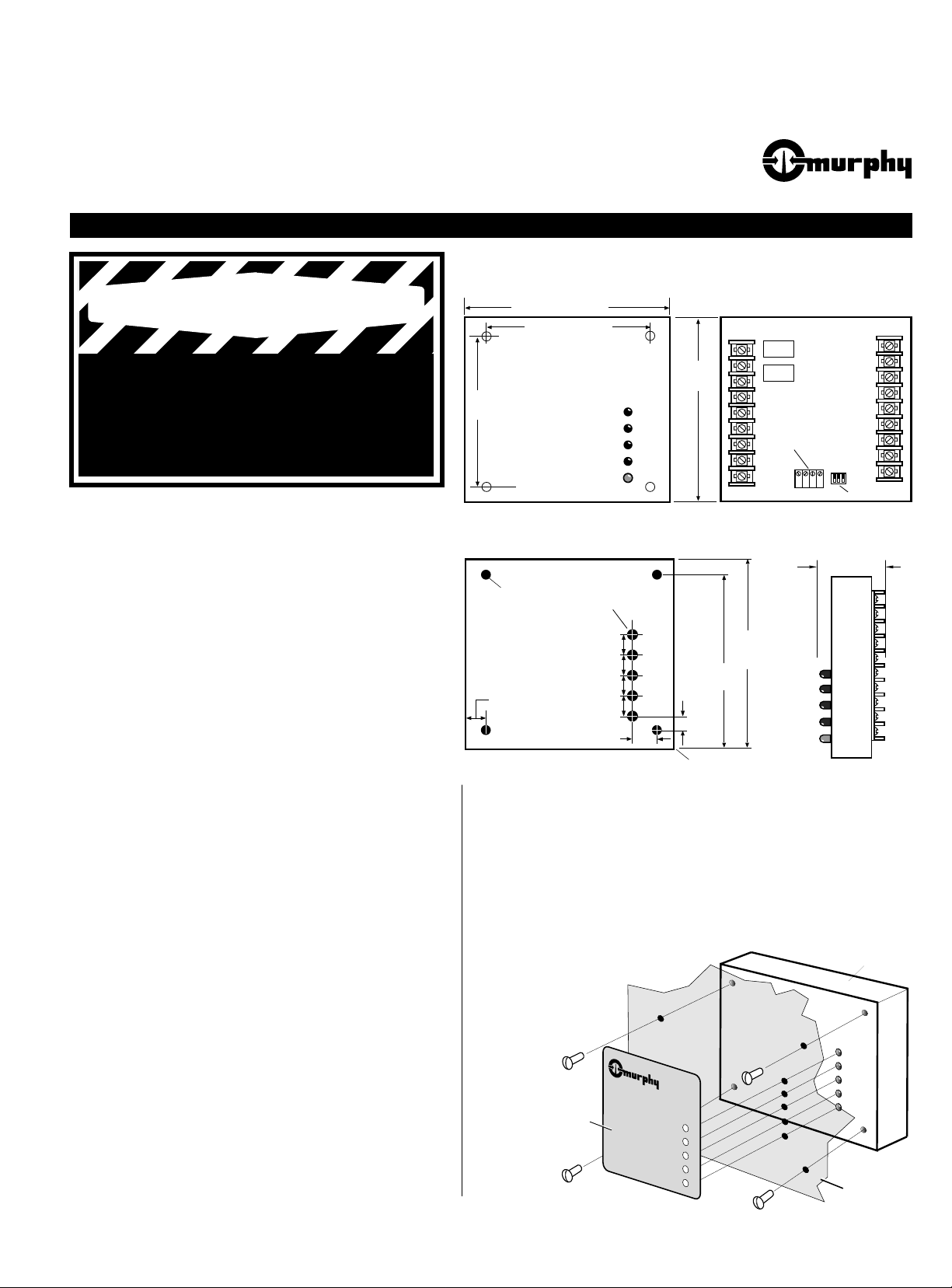
ASM160 Mounting Dimensions
ASM-97073N
Revised 3-00
Section 40
(00-02-0276)
®
FRANK W.
MFR.
Mounting Drill Pattern
Side View
Front View
Back View
0.45 in. (11 mm)
0.45 in. (11 mm)
0.45 in. (11 mm)
0.45 in. (11 mm)
Origin
0.59 in.
(15 mm)
0.20 in.
(5 mm)
0.68 in. (17 mm)
4.32 in.
(110 mm)
4.82 in.
(122 mm)
5-7/16 in. (138 mm)
1-63/64 in.
(50 mm)
4-53/64 in.
(122 mm)
0.250 in.
(6 mm) dia.
Potentiometers
DIP switches
0.203 in.
(5 mm) dia.
3-53/64 in.
(97 mm)
4-1/4 in. (108 mm)
Mounting the ASM160 Module
1.
To mount the ASM160 module to a panel, drill five (0.250 in. [6 mm] dia.) holes
for LED indicators and four (0.203 in. [5 mm] dia.) holes for the mounting
screws. See “Mounting Drill Pattern”, above, for dimensions.
2.
Insert the ASM160 module from the back of the panel into the pre-drilled holes.
See schematic below.
3.
Secure the module in place with the four mounting screws provided.
4.
Make sure the panel is clean and free of oil. Remove the adhesive cover from the
back of the ASM160 label. Position the label
on the panel and press firmly.
®
Label
Module
Panel or Wall
OIL PRESSURE
ENGINE TEMPERATURE
OVERCRANK
OVERSPEED
RUN
1
WARNING
Page 2

The ASM160 is a pilot duty device. The outputs are designed for control only .
1.
Wire the ASM160, using 14 AWG (2.5 mm2) stranded wire. When wiring to
terminal 18 (the common power for the external relay loads), we suggest using
larger wire size (12 AWG [4.0 mm2]).
2.
When hooking the battery positive (+) and ground wires to the ASM160, route
them directly from the battery to the unit. This will help reduce electrical noise
coupling and avoid voltage losses from other devices.
3.
If a standby battery charger is installed, it must be wired directly to the battery,
NOT to the ASM160. This could cause electronic "noise" produced by the
charger to be coupled into the microprocessor. If the "noise" is severe, erratic
operation will occur.
4.
Do not route low voltage DC (battery) control wires in the same conduit as
high voltage AC wires.
5.
Use shielded cable for connecting the magnetic pickup to the ASM160.
Ground only one end of the shield (suggest to ground it at the engine).
6.
Always place reverse bias diodes across inductive loads (see “Typical Wiring
Diagram”, Note: 2, below). This increases the contact life and helps eliminate a
source of electromagnetic noise.
7.
Output terminals 1 and 2 are rated for 5 A. Output terminals 3, 4, 5, 6, 7 and 8
are rated for 300 mA sinking.
WARNING:
Disconnect ALL electrical power before beginning the wiring. STOP ALL machinery before performing the hook up.
Any load connected to the panel which exceeds current ratings MUST be piloted at the load.
WIRING THE ASM160
MAKING ADJUSTMENTS TO THE ASM160
Typical Wiring Diagram
On the back of the ASM160, you will find four
(4) potentiometers and three (3) DIP switches
for customizing your controller. The four
potentiometers are designated as follows:
R1 = Overspeed Adjustment
(30-8500 Hz)
R 2 = Crank Disconnect Adj.
(30-8500 Hz)
R3 = Glow Plug or Warmup
Delay (1-300 seconds)
R4 = Cooldown Delay
(1-300 seconds) not used when
Glow Plug feature is selected.
Overspeed (R1 Pot)
The OVERSPEED pot is used to set the point at
which the unit will signal for a shutdown if the
engine speed should reach excessive RPM.
To set the OVERSPEED value, turn the OVERSPEED Pot (R1) fully clockwise and run the
engine up to the maximum operating speed.
Next, slowly turn the Pot (R1) counterclock-
wise until the engine shuts down on OVERSPEED. Now, turn Pot (R1) clockwise two
turns. This will adjust the OVERSPEED setpoint slightly higher than the maximum engine
operating speed.
Potentiometers
DIP Switches
7
8
9
10
123
ON
R1 R2
R3
R4
25 Turn Pot
ASM160 Module
Back View Detail
Potentiometer
Detail
2
NOTES:
1
Close to start and run, open to stop.
2
For Pilot Duty Only. External Load not to exceed 5 A.
Place reverse bias diodes across induction loads.
3
Remote lights (if used) not to exceed 300 mA.
4
At Load/Glow Plug Relay not to exceed 300 mA.
Fuel Test
1
Crank
2
At Load/
3
Glow Plug
Overcrank
4
Overspeed
5
Oil Pressure
6
7
O Temp.
H
2
Run
8
9
Lamp Test (IN)
Overspeed Adj.
Crank Disconn. Adj.
Spare (delayed)
Spare (immediate)
Relay Com. (B+)
Cooldown Delay
Glowplug / Warmup Delay
Auto
Gnd (-)
Mag. P/U
Oil Pressure
H2O Temp.
Number of cranks
Warmup or Glow Plug
Mode Select
2
Pilot
Relay
Starter
Assembly
4
To Battery (+)
2
3
3
Solenoid
Fuel Valve
Glowplug/At load
Pilot Relay
3
3
3
Closed Switch
For Lamp Test
Auto
Off
1
Remote
Start/Stop
10
Switch
Test
Selector
Switch
11
12
13
14
15
16
17
18
Ground or
Positive Input
Ground or
Positive Input
Ground or
Positive Input
Ground or
Positive Input
This Shutdown
is immediate with
no LED indication.
Shielded
Cable
Magnetic
Pickup
These Shutdowns
are locked out during
shutdown lockout delay
12 AWG (4.0 mm2) min.
F-1
15 Amp
12/24VDC
Battery
Battery Cable
Page 3

MAKING ADJUSTMENTS TO THE ASM160 continued
SEQUENCE OF OPERATIONS
Sequence of Operations with Panel in “Auto”
When the ASM160 receives an automatic start signal, the glow plug delay (if
selected) begins timing and the glow plug output turns on. When the delay expires,
the fuel and crank outputs turn on. When the engine starts, the glow plug output is
turned off. At this time, the Shutdown Lockout and the Warmup Time Delay (if
selected) will begin timing, and the starter will be disengaged. The Shutdown
Lockout Delay serves a dual purpose. It causes the ASM160 to disregard the signals
to the Oil Pressure and Engine Temperature inputs at engine start up. If the engine
false starts before the delay expires, the engine will re-crank after a fixed delay (35
seconds), to let the engine stop moving before engaging the starter. When the delay
expires, the Loss of Speed Signal shutdown is armed. Loss of Speed Signal occurs
when both Overcrank and Overspeed LED’s turn on if the speed drops below the
crank disconnect set point.
When the Warmup delay expires, the “At Load” output turns on (if selected).
The spare shutdown on terminal 16 is locked out during the Shutdown Lockout
Delay. The spare shutdown on terminal 17 is armed immediately. There is no LED
annunciation for either of the spare shutdowns. They are reset by moving the TestOff-Auto switch to Off position (breaking power) and back to Auto position.
If the engine speed exceeds the Overspeed set point (user adjustable), the ASM160
will signal the engine to shut down and annunciate Overspeed as the cause of shut-
down, and lockout the engine from any further start attempts. The Overspeed condition can be reset by moving the Test-Off-Auto switch into the Off position (breaking power) and back to Auto position.
If a Low Oil Pressure or High Engine Temperature shutdown condition occurs
while the engine is running, the ASM160 will signal the engine to shut down and
annunciate the failure on the appropriate LED. It will then lock out the engine from
any further start attempts. Please note that the Shutdown Lockout Delay must have
expired to get a shutdown on these functions. This is also reset by moving the TestOff-Auto switch to Off to break power and back to Auto.
When the ASM160 receives an automatic stop signal from the remote start contacts, the “At Load” output turns off, and the Cooldown time delay (if selected) will
begin timing. When this delay expires, the engine is signaled to stop.
Sequence of Operations with Panel in “Test”
When the Test - Off - Auto switch is placed in the "TEST" position, an automatic
start signal is simulated. Therefore, the controller will operate the same as it does in
"AUTO." However, it will continue to run as long as there are no signals from monitored conditions or until the Test - Off - Auto switch is moved to the "Auto" or
"Off" positions. Keep in mind, it will still shut down the engine if a monitored condition occurs such as low oil pressure or high temperature.
Crank Disconnect (R2 Pot)
The CRANK DISCONNECT adjustment is used to let the ASM160 know when the
engine has started so that it will disengage the starter. First, set the throttle at fast
idle. Now, turn the Pot (R2) fully clockwise, loosen the crank wire at Terminal #2.
Cause the engine to start and immediately disconnect the crank wire (terminal #2)
to prevent further cranking. Slowly turn the Pot (R2) counter-clockwise until the
green light (Engine Running) turns ON. This adjustment must be complete within
90 seconds, or the engine will shut down indicating OVERCRANK. If this happens, simply connect the crank wire (terminal #2), enable starter circuit, manually
reset and try again.
Glow Plug Delay (R3 Pot)
Selected by DIP Switch #3
The GLOW PLUG DELAY adjustment is used to energize the glow plug circuit.
The glow plug delay begins timing after the remote auto start signal is received, or
the controller is started in “test”. During this delay the glow plug output is turned
on. When this delay expires, the auto start sequence begins. To increase the setting,
turn the Pot (R3) clockwise. To decrease the setting, turn the Pot (R3) counter-
clockwise.
Warmup Delay (R3 Pot)
Selected by DIP Switch #3
The WARMUP DELAY adjustment is used to energize the warmup/cooldown circuit. The warmup delay begins timing after the engine starts, with the output turning on when delay expires. To increase the setting, turn the Pot (R3) clockwise. To
decrease the setting, turn the Pot (R3) counterclockwise.
Cooldown Delay (R4 Pot)
Selected by DIP Switch #3
NOTE: Cooldown delay (Pot R4) functions only when Switch #3 is turned OFF.
The COOLDOWN DELAY adjustment is used to energize the cooldown circuit.
The cooldown delay begins timing after a stop signal is received. To increase the
setting, turn the Pot
(R4)
clockwise. To decrease the setting, turn the Pot
(R4)
counterclockwise.
Overcrank Adjustments (DIP
Switches)
The ASM160 allows you to crank the engine 3, 5,
10 or infinite number of attempts (refer to the
DIP Switch Setting Chart shown below). If after
these attempts the engine fails to start, the
ASM160 will signal OVERCRANK. If infinite
number of cranks is selected, the Overcrank
shutdown will not operate. The engine will cycle
crank as long as there is sufficient battery power
available.
If the engine fails to start and the ASM160 re-crank’s the
engine, it will count this as a cranking attempt. This way, if the engine false starts
the same number of times as the selected cranking attempts, then the unit will lockout and indicate OVERCRANK.
Crank Attempts Switch 1 Switch 2
3ONON
5 ON OFF
10 OFF ON
Infinite OFF OFF
Feature Switch 3
GLOW PLUG ON
WARMUP/COOLDOWN OFF
Move Switch Up
to Turn On
123
ON
DIP Switch Setting Charts
NOTE: Switches
1 and 2 are for Crank Attempt selection
. Switch
3 is for Glow Plug or
Warmup/Cooldown feature selection.
DIP Switches
Detail
3
Page 4

Warranty
A two-year limited warranty on materials and workmanship is provided with this Murphy product.
Details are available on request and are packed with each unit.
TROUBLESHOOTING INFORMATION
WARNING:
Make sure voltage and current requirements are within the ASM160 ratings. Determine the polarity for the applica-
tion. Use appropriate wire size for voltage and current. Do NOT route/bundle AC POWER wires with any other wiring.
These instructions will assist in the correction of most problems which you may encounter with the unit. Before checking the
list, first check all wiring and connections. If problems persist after the checks, consult any Murphy facility.
SYMPTOM CORRECTIVE ACTION
When T est - Off - Auto Switch is placed in the TEST
Position, nothing happens.
Check your fuse to make sure it is good. Use a SFE 14 fuse. If good, check with a meter
to see that battery (+) is present on middle terminal of toggle switch. Also, confirm voltage is present at terminal 10 when switch is in TEST position.
Starter does not hold in long enough for the engine
to start.
Unit is possibly seeing a voltage drop. Ensure that battery is hooked directly to unit,
14 AWG wire is used, and no short circuits are present. Also make sure that the crank
disconnect pot (R2) is turned up high enough.
Odd, erratic behavior is noticed.
Check to ensure that all alternator and ignition wiring is routed in a separate wiring loom
from the rest of the control wiring. Also, confirm the use of shielded cable for the magnetic pickup. Resistor type spark plug wires and/or RF type spark plugs may be necessary for spark ignition engines.
Unit will not start when remote start / stop contact
closes.
Unit shuts down on oil pressure soon after start.
Move panel mounted Test - Off - Auto switch to the “AUTO” position.
Check oil level. Shutdown lockout delay pot is fixed at 15 seconds to give engine time to
develop oil pressure.
Engine cranks but never starts.
Make sure your fuel valve circuit is wired to terminal #1.
Engine starts but green light blinks on briefly
then goes out for 35 seconds. This occurs the
same number of times set for crank attempts.
Engine is then shutdown on Overcrank.
Check to ensure Crank Disconnect adjustment is properly set. Refer to “Crank Disconnect
(R2 Pot)” paragraph on page 3.
Output appears not to function.
Tighten connections to back of ASM160. Usually a good tight torque on the screw will
solve this problem. You can verify operation by hooking a lamp to the suspect output.
4
Printed in U.S.A.
®
FRANK W.
MFR.
FRANK W. MURPHY MFR.
CONTROL SYSTEMS & SERVICES DIVISION
P.O. Box 1819; Rosenberg, Texas 77471; USA
tel. (281) 342-0297 fax (281) 341-6006
e-mail sales@fwmurphy.com
FRANK W. MURPHY, LTD.
Church Rd.; Laverstock, Salisbury SP1 1QZ; U.K.
tel. +44 1722 410055 fax +44 1722 410088
e-mail sales@fwmurphy.co.uk
http://www.fwmurphy.co.uk
FRANK W. MURPHY FRANCE
tel. +33 1 30 762626 fax +33 1 30 763989
MURPHY DE MEXICO, S.A. DE C.V.
Blvd. Antonio Rocha Cordero 300, Fracción del Aguaje
San Luis Potosí, S.L.P.; México 78384
tel. +52-48-206264 fax +52-48-206336
e-mail ventas@murphymex.com.mx
FRANK W. MURPHY PTE., LTD.
No. 2 Tuas South Street 2,
Sprintecs Bldg., #02-01/02
Singapore 638042
tel. +65 863-1398 fax +65 863-0208
e-mail fwmsales@fwmurphy.com.sg
In order to consistently bring you the highest quality, full featured products, we reserve the right to change our specifications and designs at any time.
MURPHY SWITCH OF CALIFORNIA
41343 12th Street West
Palmdale, California 93551-1442; USA
tel. (661) 272-4700 fax (661) 947-7570
e-mail sales@murphyswitch.com
http://www.murphyswitch.com
MACQUARRIE CORPORATION
1620 Hume Highway;
Campbellfield, Vic 3061; Australia
tel. +61 3 9358-5555 fax +61 3 9358-5558
e-mail murphy@macquarrie.com.au
FRANK W. MURPHY MANUFACTURER P.O. Box 470248; Tulsa, Oklahoma 74147; USA tel. (918) 627-3550 fax(918) 664-6146 e-mail sales@fwmurphy.com http://www.fwmurphy.com
BSI
R
E
G
I
S
T
E
R
E
D
F
I
R
M
FM 28221
FM 29422
USA–ISO 9001
UK–ISO 9002
NATIONAL
ACCREDITATION
OF CERTIFICATION
BODIES
Since 1939
 Loading...