

Page 1
MGC-02029B
Revised 06-03
Catalog Section 75
(00-02-0500)
Generator Control System
FWMurphy
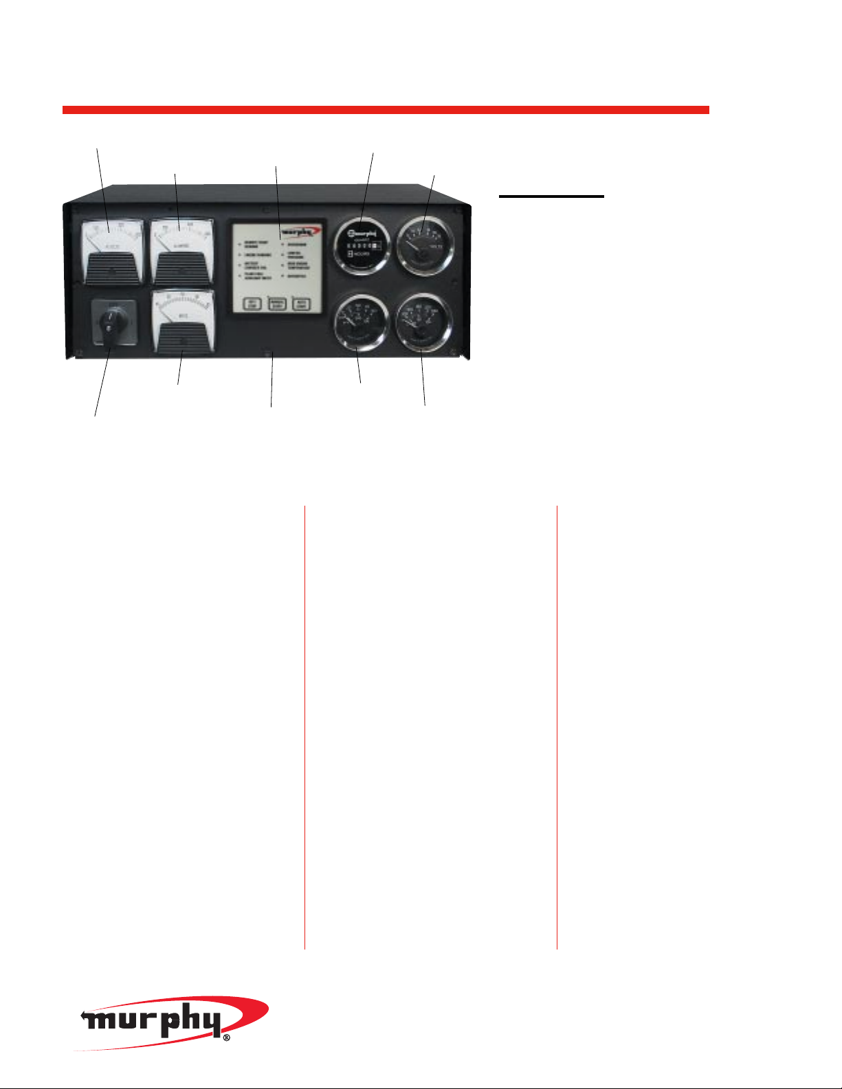
Description
The compact and powerful MGC2000 generator
control system features a unique, simple-to-install
and setup design and enhanced operation.
The control method for the MGC2000 may be
specified for using either the AS3000 Autostart
automatic controller or the 518APH electrically
tripped annunciator method.
The system is available in two basic configurations:
MGC2000
features mechanical gages:
- MGC2000-A Automatic Control: with
Murphy’s AS3000 Generator Controller.
- MGC2000-M Manual Control: with
518APH annunciator control.
Both configurations include standard AC
voltmeter, AC ammeter, and frequency meter.
Available for single-phase, standard three-phase,
and three-phase, re-configurable generators.
MGC2000E
features electric gages:
- MGC2000E-A Automatic Control: with
Murphy’s AS3000 Generator Controller.
- MGC2000E-M Manual Control: with
518APH annunciator control.
Both configurations include standard AC volt-
meter, AC ammeter, and frequency meter.
Available for single-phase, standard three-phase,
and three-phase, re-configurable generators.
Features
•
Dynamic design allows for easy installation
and full operation flexibility.
•
1/4 inch quick disconnect terminations
•
Shock mount assemblies to minimize damage
•
AC voltmeter and ammeter
•
Phase selector switch
•
Frequency meter: 45-65hz
•
Optional hourmeter; DC Voltmeter;
DC ammeter
•
First-out fault shutdown and indication
(AutoStart models only) of low oil pressure,
high temperature and auxiliary inputs
•
Inputs can be from engine-mounted fault
switches or panel-mounted SWICHGAGE
®
instruments.
•
Magnetic pickup or generator AC speed
sensing (AutoStart models only). For automat-
ic crank release and overspeed fault shutdown.
Speed calibration is automatic–adjustment free.
Additional switch inputs allow optional remote
control of crank disconnect and overspeed fault.
•
Generator AC Hz meter output: 0-1 mA.
•
User-friendly: Well-thought-out routine for
faster and easier set up.
•
Interfaces with existing equipment: functions
seamlessly with many other Murphy instruments and controls (AutoStart models only).
Specifications
Pressure Gage: 100°psi (680 kPa) [7 bar]
Mechanical Gage Pressure Connection: 1/8” NPT.
Electric Gage Pressure Connection: 2-wire.
Temperature Gage: 0-250°F (121°C)
Mechanical Gage Temperature Connection: 12ft.
(3.67 m) capillary tubing and sensing bulb.
Electric Gage Temperature Connection: 2-wire.
Enclosure: 16 Ga CRS powder coated.
Optional NEMA 4X Type Enclosure:
Water and dust tight indoor/outdoor enclosure
intended to protect enclosed equipment against
splashing, seepage, falling or hose-directed
water and severe external condensation.
AC Meters: AC ammeter and an AC voltmeter
and a frequency meter are standard features.
Ranges must be specified.
Single or Three Phase: Specify.
Control Method: may be specified:
- AS3000 Autostart automatic controller or
- 518APH Annunciator control method.
NOTE: Autostart method is highly recommended.
DC Voltage:
12 or 24 volt DC voltage must be specified.
MGC2000
■
New Dynamic Design Allows for
Easy Installation and Full Operation
Flexibility
■
Features Murphy’s AS3000 Engine/
Generator Controller
■
User-Friendly, Well Thought-out
Routine for Faster/Easier Setup
AS3000 Autostart
Generator Controller
Voltmeter
Hourmeter
Pressure Gage
Temperature Gage
Frequency Meter
1 - 3 Phase
Selector Switch
16 ga CRS Enclosure,
NEMA 4 Optional
AC Ammeter
AC Voltmeter
Page 2
Power supply:
•
Continuous voltage range: 8-35 VDC
•
Brown out voltage < 5 VDC for 2 secs (recovery to 8V)
•
Blackout voltage: 0V for 50mS (from 10V, recovery to 5V)
•
Overvoltage withstand: 50 VDC for 5 seconds (to SAEJ1810 load
dump immunity
•
Reverse voltage withstand: 100 VDC continuous
Current consumption (standby): 50mA
Current consumption (max): 500mA (plus output loads)
DC Inputs:
•
Pressure, coolant temperature
•
Closed to negative DC (±3V) on fault auxiliary and charger faults
•
Remote start positive open from positive DC to start
•
Remote start negative close to negative DC (±3V) to start.
AC Inputs:
•
Magnetic pickup: 3 – 60 VAC, 50Hz – 10 kHz.
•
Generator AC: 600 VAC max (L-L or L-N), 50/60 Hz.
Outputs:
•
Fuel: positive DC (FET switched), 5A max.
•
Crank, preheat: positive DC (FET switched), 2A max.
•
Common alarm, fault lockout negative DC (semiconductor), 300mA max.
•
Generator Hz. meter: 0 – 1 mADC (@ 45–65Hz).
Physical:
•
Operating temperature: -10 to +65 oC
•
Relative humidity: 95% @ 60 oC
•
Environmental protection: AS3000U front: IP65, NEMA4
Vibration: ISO 88528 pt.9, & 3 axis 3g
Standard terminal blocks inside the MGC2000 enclosure. Booted type
grommets for a tight seal are available.
MGC-02029B page 2 of 4
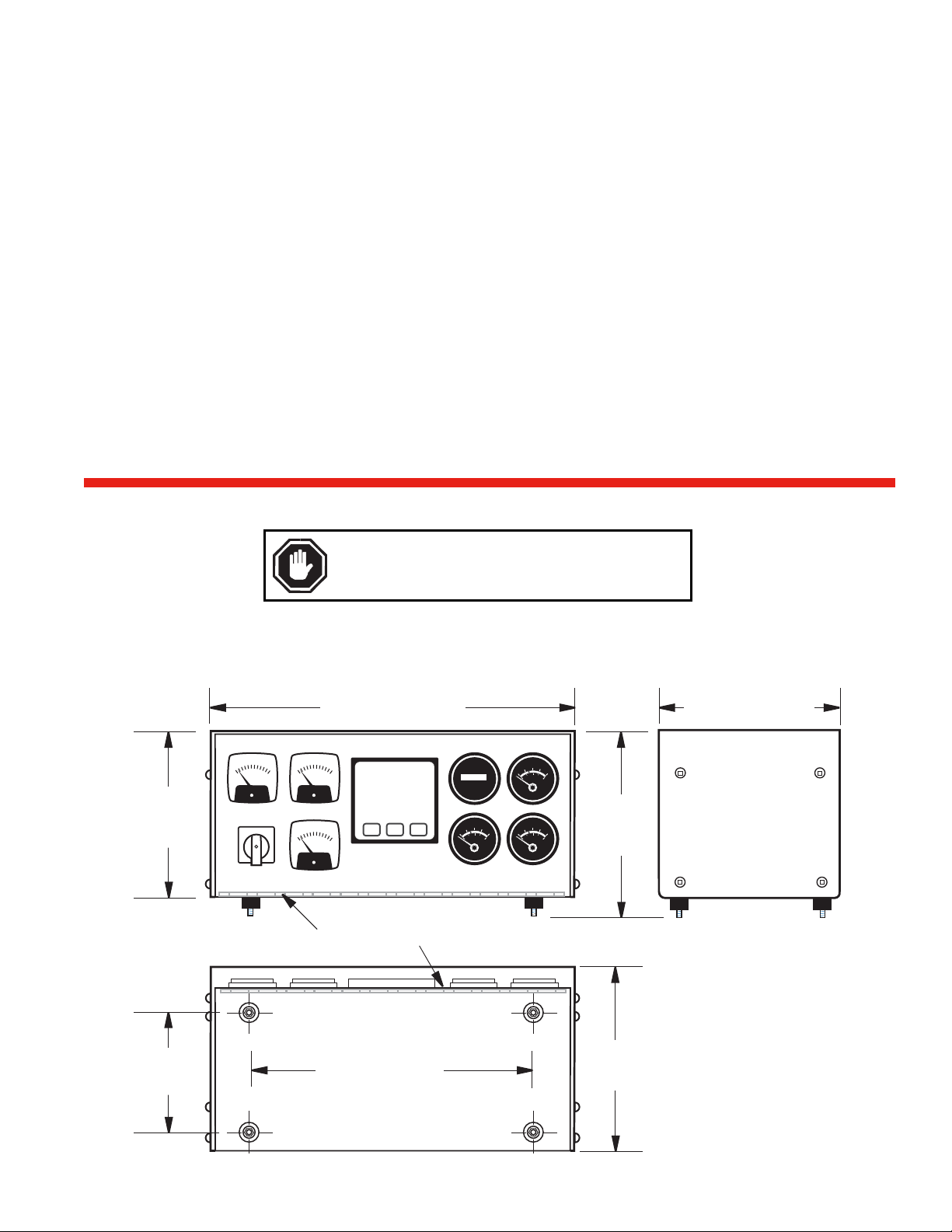
Standard Enclosure Dimensions (all Models)
ASM3000 Controller Specifications
WARNING: Do not bundle AC and DC wiring together. It is required
to use separate conduit runs and keep apart by at least 2 inches.
6.81 in.
(173 mm)
Front View Side View
16-80 in. (427 mm)
0
5
75
25
0
10
A-C
VOLTS
OFF
3
A-C
AMPERES
HERTZ
1
REMOTE START
OVERCRANK
DEMAND
ENGINE RUNNING LOW OIL
PRESSURE
BATTERY
HIGH ENGINE
CHARGER FAIL
TEMPERATURE
PLANT FAIL/
OVERSPEED
AUXILIARY INPUT
OFF/
MANUAL
STOP
START
O
H
QUARTZ
AUTO
START
5
2
0
PSI
0
kPa
Hinges for front-opening door option shown in shaded areas.
0
0
35
PSI
0
70
0
kPa
S
R
U
0
5
5
7
0
5
3
0
0
7
0
5
5
7
5
2
0
0
1
0
0
1
0
0
5
3
PSI
0
0
7
0
kPa
9.25 in. (235 mm)
7.94 in.
(202 mm)
6.36 in.
(162 mm)
Bottom View
Mounting Pattern
16-80 in. (427 mm)
9.25 in.
(235 mm)
Page 3

•
DC Voltmeter*
•
DC Ammeter*
•
Hourmeter*
•
Relays. 4 relays, wired for Preheat, Crank, Fuel, and Common Alarm
•
Keyswitch
•
Phase select switch, standard for 3-phase units, optional for singlephase units.
•
Emergency stop switch
•
NEMA-4X enclosure
•
Quick disconnect connectors
•
Hinged front panel
•
Magnetic pickup sensor
•
CT’s (current transformers)
•
User connections
•
If the Quick Disconnect option is selected, two quick disconnect connectors are provided on the rear of the enclosure, mating connectors
with 12 ft. (3.658 m) tagged leads are available.
•
If the Quick Disconnect option is not selected, grommeted holes are
provided for user’s cable entry. Connections via spade lugs will be
made to standard terminal blocks inside the MGC2000 enclosure.
Booted type grommets for a tight seal are available.
* The MGC2000 enclosure has provisions for two extra instruments only,
these two instruments can be selected in any combination.
MGC2000 System Options
MGC-02029B page 3 of 4
NEMA 4X Type Enclosure Dimensions
WARNING: Do not bundle AC and DC wiring together. It is required
to use separate conduit runs and keep apart by at least 2 inches.
13-31/32 in.
(355 mm)
10-5/8 in.
(270 mm)
MOUNTING
MGC
Panel
DETAIL
Wall or
Pedestal
A-C
VOLTS
OFF
1
REMOTE START
DEMAND
ENGINE RUNNING LOW OIL
BATTERY
CHARGER FAIL
PLANT FAIL/
AUXILIARY INPUT
STOP
0
5
7
5
2
0
0
5
3
PSI
7
0
kPa
RS
U
O
H
QUARTZ
A-C
AMPERES
OVERCRANK
PRESSURE
HIGH ENGINE
TEMPERATURE
OVERSPEED
OFF/
MANUAL
AUTO
START
START
0
5
5
2
5
0
0
0
1
0
5
3
PSI
0
0
0
kPa
HERTZ
18-63/64 in.
(480 mm)
0
5
5
7
0
0
7
5
7
5
2
0
0
1
0
0
1
0
0
5
3
PSI
0
0
7
0
kPa
18-1/2 in.
(470 mm)
5/16 x 1/2 in. (8 x 13 mm)
Mounting Holes, 4-Places
Screw
Washer
Nut
Lock
Washer
Washer
MGC
Panel
Wall or
Pedestal
Page 4

MGC-02029B page 4 of 4
How to Order the MGC2000
Phases
1 = Single Phase
3 = Three Phase
Base Model
MGC2000
= Mechanical Gages
MGC2000E =Electric Gages
Controller
A = Autostart
M = Manual
DC Voltage
12 = 12 VDC
24 = 24 VDC
AC Voltmeter
300, 600
600D = 600/300 Dual Scale
Options
AM = DC Ammeter
(1)
VM = DC Voltmeter
(1)
HM = Hourmeter
(1)
RL = Relays
KS = Keyswitch
PS = Phase Select Switch (single phase only)
ES = Emergency Stop Switch
4X = NEMA 4X Enclosure
QD = Quick Disconnect Connectors
HF = Hinged Front
MP = Magnetic Pickup Sensor
(2)
CT = Provide CT’s
(2)
NOTE: Enter Options prefix in the listed order,
example: AMVMRLKS4XMP.
(1)
Select a maximum of 2 of these 3 items.
(2)
“Shipped Loose” items.
AC Ammeter
50, 60, 75, 100, 150, 200, 300, 400, 500, 600, 800, 1000,
1200, 1500, 2000, 3000, 4000
100D= 50/100 Dual Scale
200D= 100/200 Dual Scale
300D= 150/300 Dual Scale
400D= 200/400 Dual Scale
600D= 300/600 Dual Scale
800D= 400/800 Dual Scale
1000D= 500/1000 Dual Scale
1200D= 600/1200 Dual Scale
1600D= 800/1600 Dual Scale
2000D= 1000/2000 Dual Scale
3000D= 1500/3000 Dual Scale
4000D= 2000/4000 Dual Scale
5000D= 250/5000 Dual Scale
MGC2000
1 – A – 12
– 300 – 600D – AMVMRLKS4XMP
Accessories and Replacement Parts
Off-Equipment Mounting Kit
This kit allows off-equipment mounting of the ESPM, ES2PM and ESDPM pressure senders.
Recommended for protection from damaging vibration. Customer supplies hose and fittings.
Specify part number 30-00-0213 when ordering.
Sender Description
ESP 1-wire to ground sender
†
ES2P 2-wire ungrounded sender
†
ESDP 2-wire ungrounded sender, drives two (2) gages
†
ESPM 1-wire to ground sender††**
ES2PM 2-wire ungrounded sender††**
EST 1-wire to ground sender
*
ES2T 2-wire ungrounded sender
*
ESDT 2-wire ungrounded sender, drives two (2) gages
*
Connectors
Quick Disconnect mating connectors with 12’ tagged leads.
†
Thru 100 psi (689 kPa) [6.89 bar].
††
Ranges above 100 psi (689 kPa) [6.89 bar].
** Mounting off-equipment recommended.
Warranty
A two-year warranty on materials and workmanship is given with
this FWMurphy product. A copy of the warranty may be viewed
or printed by going to www.fwmurphy.com/warranty.asp
.
CONTROL SYSTEMS & SERVICES DIVISION
P.O. Box 1819; Rosenberg, Texas 77471; USA
(281) 633-4500 fax (281) 633-4588
e-mail sales@fwmurphy.com
MURPHY DE MEXICO, S.A. DE C.V.
Blvd. Antonio Rocha Cordero 300, Fracción del Aguaje
San Luis Potosí, S.L.P.; México 78384
+52-444-8206264 fax +52-444-8206336
Villahermosa Office +52-993-3162117
e-mail ventas@murphymex.com.mx
www.murphymex.com.mx
FRANK W. MURPHY, LTD.
Church Rd.; Laverstock, Salisbury SP1 1QZ; U.K.
+44 1722 410055 fax +44 1722 410088
e-mail sales@fwmurphy.co.uk
www.fwmurphy.co.uk
MURPHY SWITCH OF CALIFORNIA
41343 12th Street West
Palmdale, California 93551-1442; USA
(661) 272-4700 fax (661) 947-7570
e-mail sales@murphyswitch.com
www.murphyswitch.com
In order to consistently bring you the highest quality, full featured products, we reserve the right to change our specifications and designs at any time.
MACQUARRIE CORPORATION
1620 Hume Highway
Campbellfield, Vic 3061; Australia
+61 3 9358-5555 fax +61 3 9358-5558
e-mail murphy@macquarrie.com.au
FWMurphy
P.O. Box 470248
Tulsa, Oklahoma 74147 USA
(918) 317-4100
fax (918) 317-4266
e-mail sales@fwmurphy.com
www.fwmurphy.com
R
E
G
I
S
T
E
R
E
D
Printed in U.S.A.
®
 Loading...