

Page 1
MeCAN™
28th November 2008
catalogue section 78
00-02-0665
Mechanical Engine to CAN J1939 interface
Installation Instructions
Please read the following information before installing. A visual inspection of this product for damage during
shipping is recommended before installation. It is your responsibility to ensure that qualified mechanical and electrical
technicians install this product. If in doubt, please contact your local Murphy representative.
GENERAL INFORMATION
WARNING
BEFORE BEGINNING INSTALLATION OF THIS PRODUCT
Disconnect all electrical power to the machine
Make sure the machine cannot operate during installation
Follow all safety warnings of the machine manufacturer
Read and follow all installation instructions
Description
MeCAN™ is a compact, encapsulated interface module that
translates resistive sender, fault switch and speed signals into
SAE J1939 CANbus data. MeCAN allows quick and simple
integration of ‘mechanical’, non-ECU engines into modern
CANbus systems. Applications include the retrofit of older
engine fleets with digital instruments, controls and telemetry,
and the development of standard control panels for both ECU
and non-ECU engines.
MeCAN has four inputs. Two inputs are for oil pressure and
coolant temperature sensing, either by fault switches or resistive
senders. One input is for engine speed sensing, using a
magnetic pickup or charge alternator. Input signals are
translated into SAE J1939 CANbus messages with appropriate
PGN address, data scaling and transmission rate.
A fourth input is for the connection of a speed calibration
potentiometer during setup mode only. DIP switches allow
selection of normal/setup mode and two speed input ranges.
An LED gives indication of operating mode and CANbus
activity.
Two standard versions allow use with a speed input and
either fault switches or Murphy ES series resistive senders:
part number model/description
79.70.0014 MEC300-1 MeCAN I/O module, for use with
Murphy ES pressure & temperature senders
79.70.0020 MEC300-2 MeCAN I/O module, for use with
pressure & temperature switches (closing to
negative DC on fault)
Custom solutions are also available for non-standard, volume
OEM requirements.
MeCAN is compact and light enough for inclusion in many
wiring harnesses, but can also be surface mounted via four
fixing holes. The case is fully sealed in epoxy resin for high
impact and environmental resistance.
Product specification
power supply: MEC300-1
(79.70.0014)
operating voltage 7 to 35 VDC
current consumption 25mA (typ.)
Inputs:
max. operating range –2 to +35 VDC
oil pressure, coolant temp sender, Murphy
ES series
speed input 10 – 60 VAC peak,
adjustable 10 – 180 pulses per rev
speed calibration 0 – 5 kOhm potentiometer
output:
CANbus SAE J1939 protocol,
120 Ohm terminating resistor fitted.
physical:
case material high-impact ABS, epoxy filled
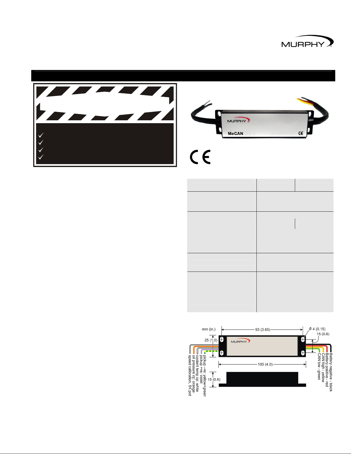
case dimensions (l x w x h) 100 x 25 x 15 mm / 4.0 x 1.0 x 0.6 in
weight approx. 60g / 0.13 lb
operating temperature –20°C to +85°C / -4°F to +185°F
environmental sealing IP65 case (with DIP switch film
intact), exposed lead ends
electromagnetic compatibility 2004/108/EC
MEC300-2
(79.70.0020)
switch, closed to
negative on fault
Connection & dimensions
Page 2
ELECTRICAL CONNECTION & CONFIGURATION
Electrical connection
MeCAN connection is via 9 colour-coded flying leads
(see diagram on page 1).
RED: Power supply positive DC
BLACK: Power supply negative DC
Connect these wires to a smooth DC power supply in the range
7 to 35 VDC. A 1 Amp anti-surge fuse is recommended in the
positive DC line.
MeCAN operates with negative earth/ground or fully insulated
DC systems. DO NOT use MeCAN with positive earth/ground
systems.
YELLOW: CANbus high
GREEN: CANbus low
Connect these wires to the engine’s CANbus, using the
appropriate twisted-pair cable to J1939 specification. MeCAN
includes a non-removable 120 Ohm CAN terminating resistor.
VIOLET: Speed input signal
YELLOW / GREEN: Speed input return
GREY: Speed input calibration (5kOhm potentiometer)
Connect the violet wire to a magnetic pickup or charge
alternator speed signal output. Connect the yellow/green
wire to the speed signal return wiring (or battery negative,
on ground/ negative-return systems). This input requires a
speed signal of 10 – 60 VAC peak.
Before speed input calibration (see section right), connect
a 5kOhm potentiometer between the grey wire and battery
negative DC. MeCAN allows adjustment for speed signals
between 10 and 180 pulses per engine revolution. The
potentiometer can be removed in normal operation.
BLACK: Sender/switch common (negative DC)
WHITE: Coolant temp sender/switch input
ORANGE: Oil pressure sender/switch input
Part number 79.70.0014 is designed for use with Murphy
ES series resistive senders: see separate product info for
pressure and temperature versus resistance data. For best
measurement accuracy, use insulated return (2-wire) senders.
Connect one terminal of each sender to the appropriate
MeCAN input lead; connect the other sender terminals to
MeCAN’s Sender Common (black) wire. Where 1-wire
(negative DC/ground return) senders are used, connect
the black (sender common) wire to battery negative.
79.70.0020 is configured for use with switch contacts that close
to negative DC on fault. For insulated return (2-wire) switches,
connect one switch terminal to the appropriate MeCAN input;
the second terminal from each switch (on 2-wire switches) or
the body ground (on 1-wire switches) must be connected to
MeCAN’s sender/switch common (black) wire.
Speed input calibration
MeCAN’s speed sensing input must be correctly calibrated
before speed data can be correctly transmitted.
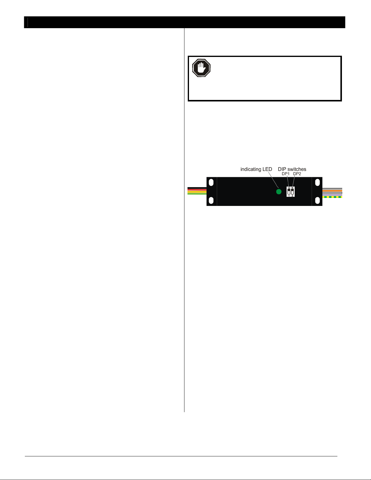
WARNING: speed calibration requires the setting
of 2 DIP switches, which are environmentally
protected by an adhesive film. To maintain sealing
integrity, use a scalpel to carefully lift the film from
the DIP switch, make switch adjustments, then
replace the film firmly to ensure a good seal.
The speed calibration procedure is as follow:-
a) Ensure minimum connection (details shown left) of CANbus,
speed signal and (isolated) DC power supply wiring.
b) Connect a 5 kOhm potentiometer between MeCAN’s
calibration input (grey wire) and battery negative DC.
c) Connect (to the CANbus) and power-up a J1939 compatible
RPM display, e.g. Murphy PowerView® PV101.
d) Set MeCAN switch DP1 to OFF (down) for calibration mode:
e) Set switch DP2 for the speed sensor range, if known:
- ON (up) = 10 to 62 pulses per rev
- OFF (down) = 55 to 180 pulses to rev
f) Run engine to known speed.
g) Power-up MeCAN. The LED flashes rapidly to indicate
calibration mode.
h) Adjust the 5kOhm calibration potentiometer until the J1939
RPM display indicates the known engine speed. If the
indicated speed is too high/low and cannot be adjusted
downward/upward, power down MeCAN, switch DP2 to a
lower/ higher speed range, then repeat the procedure from
g) above.
i) Once the correct speed is indicated (and with MeCAN still
powered), switch DP1 to ON (up) to save the calibration
setting. Normal operation then resumes, indicated by a
continuously lit LED (if CANbus traffic is detected) or a
slow flashing LED if CANbus traffic is not present).
j) Stop the engine and power-down MeCAN. The 5kOhm
calibration resistor is not required for normal operation and
may be removed. Restart the engine, power-up MeCAN and
check for correct operation.
Mounting
MeCAN uses an epoxy-resin filled polycarbonate case for
high impact and environmental resistance. The case is
compact and light enough for inclusion in (or tie-wrapping to)
an engine wiring harness; or it can be surface mounted via 4 x
M4 (0.15 in) holes - see diagram on page 1 for dimensions.
FW Murphy – MeCAN MEC300 installation instructions 00-02-0665 28th November 2008 p2/3
Page 3

OPERATION AND MAINTENANCE
Operation
MeCAN begins transmitting J1939 CANbus data immediately
after power-up. Data can be viewed using a J1939 compatible
display, e.g. the Murphy PV101, or used as part of a J1939
control system, e.g. Murphy CANstart or CASCADE modules.
Engine oil pressure and coolant temperature
Model 79.70.0014 transmits pressure and temperature data
when the sender input is within normal resistance range.
MeCAN also transmits appropriate SPN (Suspect Parameter
Number) and FMI (Fault Mode Indicator) codes if:
• input resistance is out of normal sender range, e.g. open-
or short-circuit
• oil pressure drops below 20 psi (warning message) and
10 psi (shutdown/derate message)
• coolant temperature rises above 90°C/194°F (warning
message) or 110°C/230°F (shutdown message)
Model 79.70.0020 transmits pressure and temperature data in
accordance with the switch position:
Input switch
closed (to –DC)
oil pressure data 0 psi &
SPN/FMI code
coolant temp data 105°C / 221°F &
SPN/FMI code
Oil pressure fault codes are not transmitted until 10 seconds
after engine starting (once speed has risen above 800 RPM).
Engine speed data
RPM data is transmitted whenever a speed signal is present
(above the minimum 10VAC peak). If engine speed exceeds
3500 RPM, MeCAN also transmits the appropriate overspeed
fault SPN and FMI codes.
Battery voltage
MeCAN measures its DC power supply voltage and transmits
this as J1939 ‘electrical potential’ data (PGN 65271).
Hours run
MeCAN transmits ‘engine hours run’ data (PGN 65253).
The hours run value is stored in non-volatile flash memory
and increases only while engine speed is above 500 RPM.
To prolong flash memory life, hours run data is updated at
3 minute intervals.
Input switch
open
100 psi
90°C / 194°F
Maintenance and Warranty
MeCAN contains no user-serviceable parts. Maintenance is
therefore limited to the following preventative checks:
• Check that MeCAN electrical connections are secure.
• Check that the case is mounted securely, with vibration
and environmental exposure minimised where possible.
The case may be wiped with a clean, damp cloth. Do not
use cleaning solvents.
MeCAN is supplied with a two year warranty on parts and
workmanship. In the event of a fault or technical query,
and before returning equipment, please contact your
Murphy representative for technical support.
In order to consistently bring you the highest quality, full featured products, we reserve the right to change our specifications and designs at any time.
FW MURPHY
P.O.Box 470248, Tulsa, Oklahoma 74147 USA
+1 918 317 4100 Fax: +1 918 31 7 4266
E-mail: sales@fwmurphy.com
INDUSTRIAL PANEL DIVISION
Fax: +1 918 317 4124
E-mail: ipdsales@fwmurphy.com
MURPHY POWER IGNITION
Website: www.murphy-pi.com
CONTROL SYSTEMS AND SERVICES DIVISION
P.O.Box 1819, Rosenberg, Texas 77471 USA
Phone: +1 281 633 4500 Fax: +1 281 633 4588
E-mail: sales@fwmurphy.com
FW Murphy – MeCAN MEC300 installation instructions 00-02-0665 28th November 2008 p3/3
MURPHY, the Murphy logo, are registered and/or common law trademarks of Murphy Industries, Inc. This document, including
textual matter and illustrations, is copyright protected by Frank W Murphy Ltd., with all rights reserved. © 2008 Frank W Murphy Ltd.
FRANK W. MURPHY LTD.
Church Rd, La verstock,
Salisbury, SP1 1QZ, United Kingdom
Tel: +44 1722 410055
Fax: +44 1722 410088
E-mail: sales@fwmurphy.co.uk
Web: www.fwmurphy.co.uk
COMPUTRONIC CONTROLS
41 – 43 Railway Terrace, Nechells,
Birmingham, B7 5NG, United Kingdom
Tel: +44 121 327 8500
Fax: +44 121 327 8501
E-mail: sales@computroniccontrols.com
Web: www.computroniccontrols.com
FW MURPHY INTERNATIONAL TRADING (SHANGHAI) CO. LTD.
Suite 1704 , Tower B, City Centre of Shanghai; 100 Zunyi Road,
Shanghai, 200051 China
Phone: +86 21 6237 2082 Fax: +86 21 6237 2083
E-mail: mhong@fwmurphy.com
FW MURPHY INSTRUMENTS (HANGZHOU) CO. LTD.
rd
77 23
Street, Hangzhou Economic & Technological Development Area
Hangzhou, Zhejiang 310018 China
Phone: +86 571 8788 6060 Fax: +86 571 8684 8878
 Loading...