

Page 1

M2 Wireless
Hub and Remotes
Installation Manual
00-02-0674
10-24-08
Section 50
Page 2

In order to consistently bring you the highest quality, full featured products, we reserve the right to change our
specifications and designs at any time. The latest version of this manual can be found at www.fwmurphy.com.
Warranty
the warranty may be viewed or printed by going to www.fwmurphy.com/support/warranty.htm
-
A limited warranty on materials and workmanship is given with this FW Murphy product. A copy of
Please read the following information before installing.
BEFORE BEGINNING INSTALLATION OF THIS MURPHY
PRODUCT:
• Read and follow all installation instructions.
• Please contact FW MURPHY immediately if you have any
questions.
Page 3

Table of Contents
Table of Contents ............................................................................................. iii
M2 Hub and Wireless Remotes ....................................................................... 1
Before you begin…. ..................................................................................................... 1
Tools and Equipment needed ...................................................................................... 1
Installing the M2 Wireless Hub and Antenna ................................................ 2
Hub Activation ................................................................................................... 3
Program the Network Address .................................................................................... 3
Hub Power Up – No Remotes Added Yet .................................................................... 4
Hub Power Up – Remotes Already Added .................................................................. 4
Hub Power Up – VBAT Less Than 6.6 Volts but Greater Than 5.0 Volts .................... 4
Hub – How to Reset the Hub to Factory Defaults ........................................................ 5
Installing Remote Units .................................................................................... 6
Remote Activation ............................................................................................. 8
How to Add a Remote to the Network ......................................................................... 8
How to Remove a Remote from the Network .............................................................. 9
How to Reset the FET’s and Failure Counters ............................................................ 9
FCC Compliance & Warnings ........................................................................ 10
FCC Compliance ....................................................................................................... 10
Warnings ................................................................................................................... 10
Page 4

(THIS PAGE INTENTIONALLY LEFT BLANK)
Page 5

M2 Hub and Wireless Remotes
Before you begin….
Survey the location site and determine the best location for the antenna and remote units. For
optimal performance, the remote units should be placed in clear line of site, or unobstructed
view to the antenna.
WARNING! Shut down engine before installing M2 components.
Tools and Equipment needed
• PC, including cable to connect to RS485
• MODBUS configuration software is required for initial setup and activation. Listed
below are two options that may be downloaded from the following sites:
o Murphy MConfig Software (www.fwmurphy.com/support/software.htm)
o Calta Computer Systems Modbus Interface (www.calta.com)
• Wire cutter, stripper
• Screw driver
• Conduit, as needed for remote elevation
• Teflon tape
Section 50 00-02-0674
10-24-08 - 1 -
Page 6
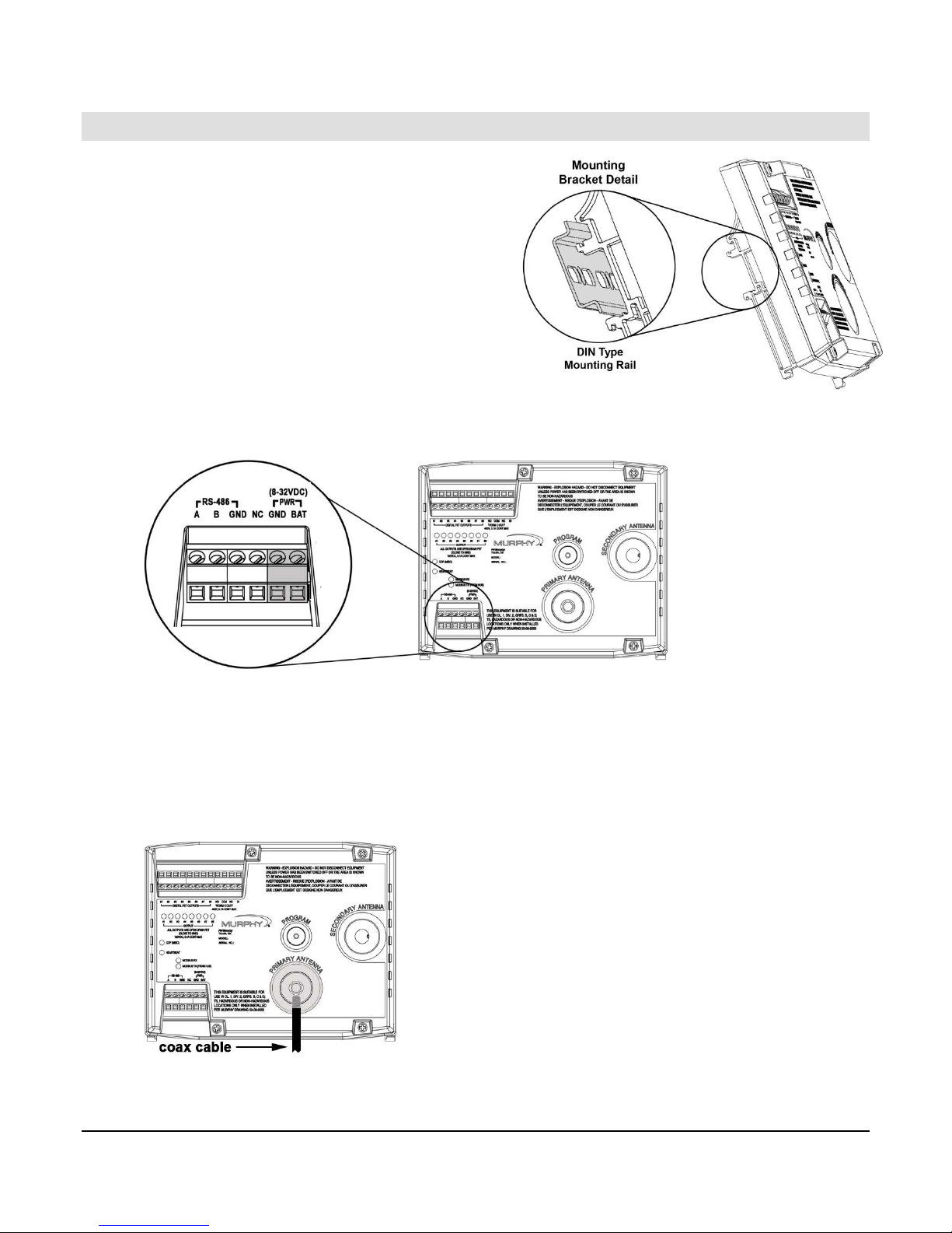
Installing the M2 Wireless Hub and Antenna
1. Mount the M2 Hub on a DIN rail inside the
panel enclosure.
The M2 Hub can be mounted vertically or
horizontally on a standard DIN rail. Two
clamp-type feet along the bottom of the hub
attach to the DIN rail, however, rail stops
are recommended to prevent sliding.
2. Add power to the hub by attaching a power cable to the GND/BAT pins and connecting
to a battery or power supply. Voltage must be between 8-32 volts DC.
3. Mount the antenna bracket to the top of the panel, or other structure, no more than 25
feet away from the hub.
4. Attach the coax cable to the Primary Antenna connection on the hub. Feed cable down
and outside of the panel through one of the conduit holes.
Section 50 00-02-0674
10-24-08 - 2 -
Page 7

5. Attach the cable to the antenna through the mounting bracket, locking the antenna into
place.
Hub Activation
Connect PC cable to RS-485 connection on the hub. Use the MODBUS configuration software
on the PC to program the network address.
Program the Network Address
1. Verify the Hub is powered up.
2. To enable MODBUS writes, send a value of 0x1234 to MODBUS address 53
3. Set the network address by sending a unique value to MODBUS address 51
4. Verify that the value was programmed via the MODBUS map.
IMPORTANT!
Network address must be programmed before Learn Mode can be
enabled.
It is the installer’s responsibility to maintain a list of network addresses at
the location.
Each hub must have a unique address.
It is recommended that network addresses be offset by values of 5.
The highest network address is 255.
Section 50 00-02-0674
10-24-08 - 3 -
Page 8

Hub Power Up – No Remotes Added Yet
• The ‘Heartbeat’ LED will start flashing on a periodic basis.
• All of the ‘Output’ LED’s will be off
• If there is MODBUS communication with the Hub, then the MODBUS LED’s will be
flashing; otherwise they will be off.
• The ‘Form C’ output will be shorted between ‘COM’ & ‘NC’ after the Hub has been
powered up for 2 seconds.
Hub Power Up – Remotes Already Added
• The ‘Heartbeat’ LED will start flashing on a periodic basis.
• All of the ‘Output’ LED’s will be off for at least 90 seconds.
• If there is MODBUS communication with the Hub, then the MODBUS LED’s will be
flashing; otherwise they will be off.
• The ‘Form C’ output will be shorted between ‘COM’ & ‘NO’ until all Remotes have
reported in.
• As soon as all Remotes report in subsequent to Hub power up, then the ‘Form C” output
will be shorted between ‘COM’ & ‘NC’.
• In the event all Remotes do not report in within 90 seconds, the ‘Output’ LED(s)
corresponding to the Remote(s) that have not reported in will be illuminated and the
‘Form C’ output will not change state.
Hub Power Up – VBAT Less Than 6.6 Volts but Greater Than 5.0 Volts
• The ‘Heartbeat’ & ‘Misc’ LED’s are on and do not go off.
• When VBAT > 6.6 volts, the ‘Misc’ LED will go off and the ‘Heartbeat’ LED will start
flashing on a periodic basis.
Section 50 00-02-0674
10-24-08 - 4 -
Page 9

Hub – How to Reset the Hub to Factory Defaults
• Power up the Hub.
• On the Hub, write a value of 0x1234 to MODBUS address 53 to enable MODBUS
writes.
• On the Hub, write a value of 0x2355 to MODBUS address 99.
• Wait at least 5 seconds.
• Turn off Hub power.
• Wait at least 10 seconds.
• Turn Hub power back on.
Section 50 00-02-0674
10-24-08 - 5 -
Page 10

Installing Remote Units
Using the MODBUS program, determine the next remote ID by looking at MODBUS addresses
7 and 8. If 7 and 8 are not the same, then view the remote MODBUS map and look for an
unused location. If 7 and 8 are the same, then the next remote location will be the next
number after the value in 7 and 8.
You will want to label each remote unit with its corresponding Hub LED number and MODBUS
address.
NOTE: The first 8 remote units correspond to Hub LEDs 1 through 8.
Additional remotes will use LED 8 to display any errors.
When an error occurs, the hub will light up the appropriate LED 1 through
8.
1. Loosen the 4 screws and remove the lid to the remote
enclosure. Take out the PC board and place it onto the
lid. Set aside for later.
2. Place 2 wraps of Teflon tape in a clockwise fashion
around threaded connection.
3. Run sensor wires into the remote case, leaving
approximately 1 foot of extra wire outside of the case.
4. Attach the remote case to the sensor or conduit, leaving
the case opening face up.
5. Snap the battery into place on the back side of the pc board,
aligning the +/- as indicated below.
NOTE: Use only Tadiran TL-5903-S 3.6 volt Lithium batteries.
6. Replace the PC board into the casing, battery side down.
Section 50 00-02-0674
10-24-08 - 6 -
Page 11

7. Trim wires and strip ends approximately 9/32 inch
minimum.
8. Place wire ends in slot and screw down until snug.
NOTE: Make sure wire connects directly to
the J301 connector without looping the wire
inside casing.
9. Rotate the remote unit clockwise to 90° vertical
position.
10. Repeat steps 1-9 for each additional remote unit. Do
not replace lid until the remote has been activated
and is recognized by the hub.
NOTE: The sensor resistance must be less than 45k Ohm. If the sensor
is greater than 45k Ohm, then excessive current will flow and reduce
battery life.
11. Follow the instructions for “Remote Activation”. Ensure the signal is recognized by the
hub before replacing the lid in the next step.
12. Replace the lid. Hand tighten all 4 screws, then tighten to snug in the following order.
IMPORTANT! In order to meet NEMA 4 requirements, ensure all 4
screws are used to hold the lid in place.
Section 50 00-02-0674
10-24-08 - 7 -
Page 12

Remote Activation
After adding the remote units, use the PC to send a command to the hub to Reset Faults
(MODBUS address 40098). This will clear any LED fault lights on the hub.
How to Add a Remote to the Network
• Power up the Hub.
• If necessary, Reset the Hub to Factory Defaults – this is done if the Hub is used at a
new location.
• Verify the Network address has been programmed into the Hub.
• Install a battery in the Remote – wait until the LED’s stop flashing.
• Press and hold S301 on the Hub until LED1 flashes rapidly, followed by two slower
flashes, then release.
• LED1 should flash two times to confirm the command; turn off for approx 1 second; then
flash rapidly indicating it is in learn mode
• Press and hold the switch on the Remote until DS302 flashes two times, then release.
• Verify that DS302 flashes two times to confirm the command
Section 50 00-02-0674
10-24-08 - 8 -
Page 13

• Subsequent to DS302 flashing, DS301 should flash very rapidly followed by DS302
flashing two times.
• If the above steps do not proceed as explained, then the Remote was not added to the
network.
• If the above steps succeed, then press the switch on the remote and release
immediately to initiate normal heartbeat operation.
NOTE: Remote #1 is located between MODBUS registers 200-249;
Remote #2 is between registers 250-299, and so on.
The system supports up to 10 Remotes.
How to Remove a Remote from the Network
• Power up the Hub.
• On the Hub, write a value of 0x1234 to MODBUS address 53 to enable MODBUS
writes.
• On the Hub, write a remote ID to be removed to MODBUS address 55 to remove the
remote from the network.
• Continue removing any undesired remotes.
• Write a value of 0xA1 to MODBUS address 98 to reset the FET outputs on the HUB –
verify the FET LED’s are off.
How to Reset the FET’s and Failure Counters
• Power up the Hub.
• On the Hub, write a value of 0x1234 to MODBUS address 53 to enable MODBUS
writes.
• On the Hub, write a value of 0xA1 to MODBUS address 98 to clear the FET’s..
• On the Hub, write a value of 0xA3 to MODBUS address 98 to reset the counters.
Section 50 00-02-0674
10-24-08 - 9 -
Page 14

FCC Compliance & Warnings
FCC Compliance
• This equipment has been tested and found to comply with the limits for a Class B
digital device, pursuant to part 15 of the FCC Rules.
• Operation is subject to the following two conditions: (1) this device may not cause
harmful interference, and (2) this device must accept any interference received,
including interference that may cause undesired operation.
• The FCC Class B limits are designed to provide reasonable protection against
harmful interference in a residential installation. This equipment generates, uses,
and can radiate radio frequency energy and, if not installed and used in accordance
with the instructions, may cause harmful interference to radio communications.
However, there is no guarantee that interference will not occur in a particular
installation. If this equipment does cause harmful interference to radio or television
reception, which can be determined by turning the equipment off and on, the user is
encouraged to try to correct the interference by one or more of the following
measures:
o Reorient or relocate the receiving antenna.
o Increase the separation between the equipment and receiver.
o Connect the equipment into an outlet on a circuit different from that to which
the receiver is connected.
o Consult the point of purchase or service representative for additional
suggestions.
• The manufacturer is not responsible for any radio or television interference caused
by using other than recommended cables or by unauthorized changes or
modifications to this equipment. Unauthorized changes or modifications could void
the user's authority to operate this equipment.
• This equipment must be installed by qualified professionals or contractors in
accordance with FCC Part 15.203, Antenna Requirements.
• Do not use any antenna other than the one provided for the unit.
Warnings
• RF Exposure – To comply with FCC RF exposure requirements for mobile
transmitting devices, this equipment should only be used or installed at locations
where there is normally at least a 12 inch separation between the antenna and all
persons. NOTE: The remote contains an internal antenna while the hub uses an
external antenna.
• Do not co-locate and operate in conjunction with any other antenna, antenna cable,
or transmitter.
• Changes or modifications not expressly approved by Recognition Source could void
the user’s authority to operate this equipment.
Section 50 00-02-0674
10-24-08 - 10 -
Page 15

(THIS PAGE INTENTIONALLY LEFT BLANK)
Section 50 00-02-0674
10-24-08 - 11 -
Page 16

MURPHY and the Murphy logo are registered and/or common law trademarks of Murphy Industries, Inc. This
document, including textual matter and illustrations, is copyright protected by Murphy Industries, Inc., with all
rights reserved. (c) 2008 Murphy Industries, Inc. Other third party product or trade names referenced herein are
the property of their respective owners and are used for identification purposes only.
Section 50 00-02-0674
10-24-08 - 12 -
Page 17

 Loading...