

Murphy LM500, LM500-TF Installation Instructions Manual
Lube Level Maintainer
Models LM500/L M500-TF
Installation Instructions
00-02-0729
2015-05-30
Section 15

BEFORE INSTALLING THIS MURPHY PRODUCT:
• A visual inspection of this product for damage during shipping is
recommended before installation.
• It is your responsibility to ensure that qualified mechanical and electrical
technicians install this product.
• Disconnect all electrical power to the machine.
• Make sure machine cannot operate during installation.
• Follow all safety warnings of the machine manufacturer.
• Read and follow all installation instructions.
• Please contact Enovation Controls immediately if you have any questions.

Table of Contents
General Information ............................................................................................................................. 1
Description ........................................................................................................................... 1
Dimensions .......................................................................................................................... 1
Range of the Snap-Switch.................................................................................................... 2
Test Feature ......................................................................................................................... 2
Thumb-ValveTM Operation .................................................................................................... 3
LM500 Series Flow Rates .................................................................................................... 3
Service Parts (Specify part number) .................................................................................... 4
Hose Kit (P/N 15000355) ..................................................................................................... 4
Vent Fittings Kit (P/N 15000954) .......................................................................................... 4
Fittings Kit (P/N 15000943) .................................................................................................. 4
Bubble Lens Kit (P/N 15000532) .......................................................................................... 4
Typical Installation ............................................................................................................................. 5
Mount the LM500 ................................................................................................................. 5
Pipe Bracket Mount (PM) (P/N 15000518) ........................................................................... 5
Universal Bracket Mount (UB) (P/N 15000519) .................................................................... 6
Base Mounting ................................................................................................................. 6
Crankcase (Oil Pan) Mounting ......................................................................................... 6
Connect Fittings and Hoses ................................................................................................. 7
Connect LM500 to Oil Supply Tank ...................................................................................... 8
LM500 Typical Installation Shown ........................................................................................ 8
Specifications ..................................................................................................................................... 9

THIS PAGE INTENTIONALLY LEFT BLANK
General Information
Description
The Murphy LM500 model maintains the crankcase oil level of an engine, pump or
compressor. Adjusted to the correct running oil level, the LM500 will replenish oil as it is used.
The low level switch will alarm and/or shut down the equipment if the supply oil is lost and the
equipment continues to use oil. The LM500-TF model includes a test fea tur e that confirms both
the float and switch are operating correctly with a single press of the test button.
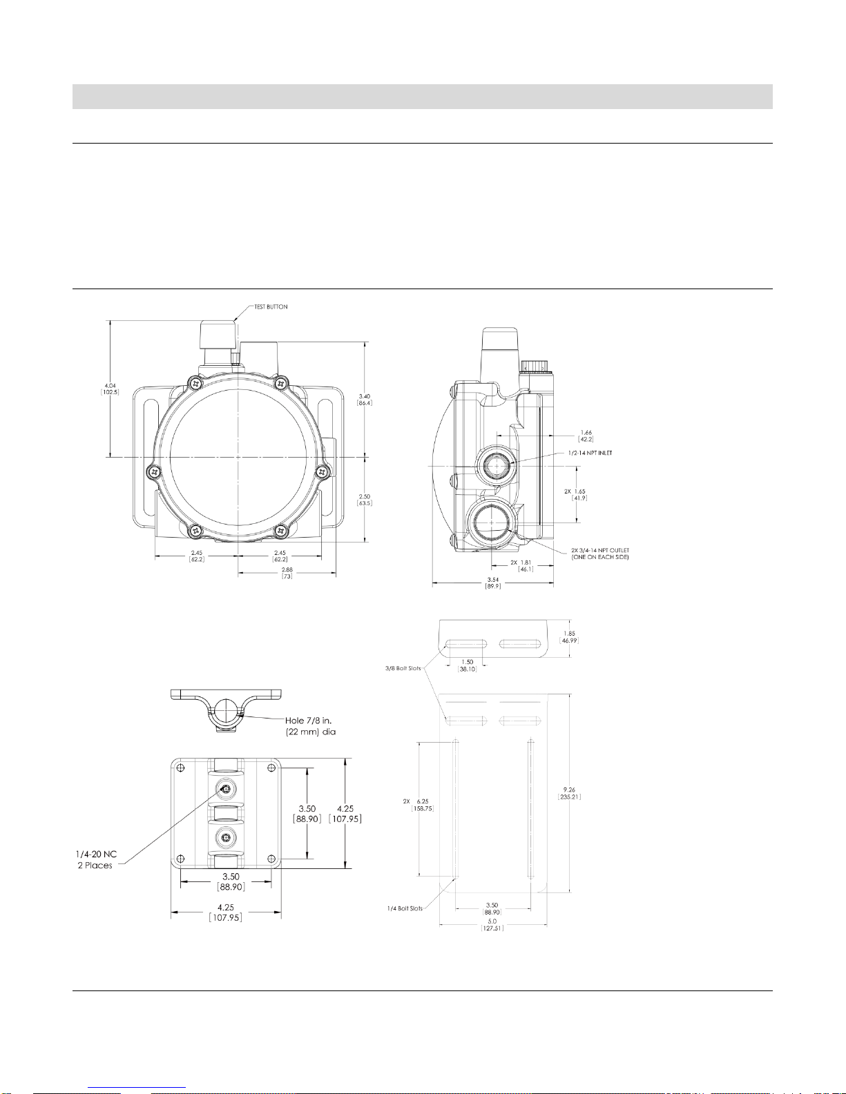
Dimensions
Pipe Mount Universal Mount
Section 15 00-02-0729
2015-05-30 - 1 -
 Loading...