

Page 1
Description
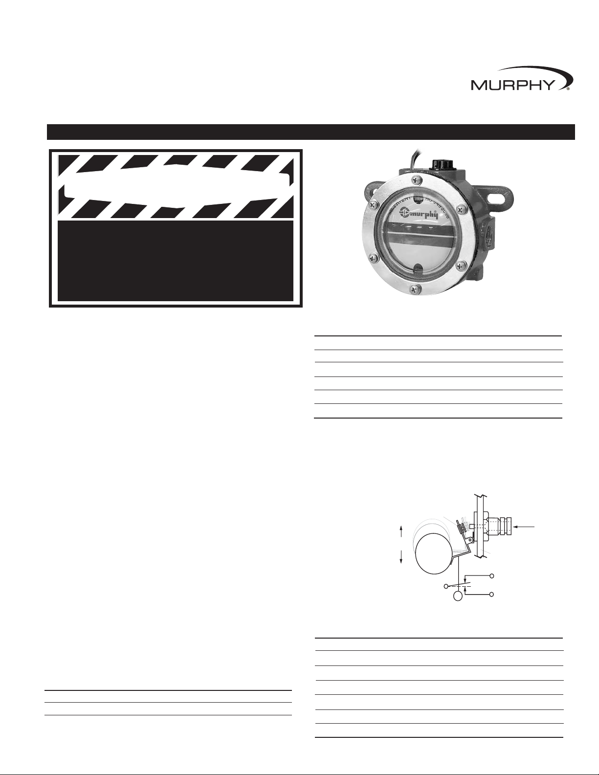
The Murphy LM2000 model maintains the crankcase oil level of an engine,
pump or compressor. Adjusted to the correct running-oil-level, the LM2000 will
replenish oil as it is used. An integral, low-level switch will alarm and/or shutdown the equipment if supply oil is lost and the equipment continues to use oil.
Specifications
Crankcase Balance Vent Connection: 1/2 NPTF (top).
Inlet Connection: 1/2 NPTF with removable screen (side).
Outlet Connection: LM2000 3/4 NPTF (bottom).
LM2000S 2 x 3/8 NPTF (side)
1 x 3/4 NPTF (bottom)
Thumb-ValveTMMaterial: Viton.
Snap-switch: SPDT rating 10 A, 125 VAC; 0.5 A, 125 VDC; 10 A, 30 VDC.
Wire leads: 18 AWG x 24 in.(609 mm) length.
Conduit Connection: 1/2 inch conduit (female, top).
Case: Die cast aluminum
Lens: Clear “Frog Eye” non-staining, high impact, high temperature nylon; UV
and heat stabilized.
Dial: High visibility white background with green and white “index” lines
for normal level indication.
Maximum Inlet Pressure: 9.50 psi/25 ft. oil (head pressure).
Maximum Case Pressure: 15 psi (103 kPa).
Maximum Differential: 2 in. (51 mm) between running and stopped.
Maximum Ambient Temperature: 250°F (121°C).
Float: Brass
Flow Rates: SAE 40 motor oil @ 32°F (0°C) with 2 ft. head pressure: 0.5
GPH (1.9 LPH).
NOTE: Friction losses due to piping not considered.
Optional Vent Fittings Kit: 15000954
The 15000943 kit is sold separately. It includes the following items:
Quantity Description
1 Tubing vent (15050202).
1 1/4 x 1/4 NPT Connector (85030447).
Optional Hose Kit:
15000355
Quantity Description
1 1/2 in. (13 mm) I.D. x 3 ft. (914 mm) long hose (89020202)
1 1 in. (25 mm) I.D. x 3 ft. (914 mm) long hose (89020203)
2 1/2 in. (13 mm) worm gear clamp (00003502)
2 1 in. (25 mm) worm gear clamp (00003503)
2 1/2 NPT x 1/2 in. (13 mm) barbed fitting (89080801)
2 3/4 NPT x 1 in. (25 mm) barbed fitting (89081001)
Thumb-Valve™ Operation
As the equipment uses oil, the float falls, providing immediate level compensation. At FULL position, the float holds the valve closed. If the clean oil
supply is depleted and oil level continues to fall, the low level switch will
operate an alarm or equipment shutdown.
Service Parts
(Specify part number)
Description Part Number
Vent Fittings Kit 15000954
Hose Kit 15000355
1/2NPT x 1/2 in. Hose Barbed Fitting 89080801
3/4NPT x 1/2 in. Hose Barbed Fitting 89081001
3/8NPTF x 1/2 in. Hose Barbed Fitting 89080601
Pipe Bracket Kit 15000238
Universal Flange Kit 15010224
LM2000/LM2000S Lube Level Maintainer
Installation Instructions
LM-00011N
Revised 10-03
Section 15
(00-02-0423)
BEFORE BEGINNING INSTALLATION OF THIS MURPHY PRODUCT
✔ Disconnect all electrical power to the machine.
✔ Make sure the machine cannot operate during installation.
✔ Follow all safety warnings of the machine manufacturer.
✔ Read and follow all installation instructions.
Please read the following information before installing. A visual inspection of this product for damage during shipping is
recommended before mounting. CRANKCASE MUST BE DRAINED BEFORE INSTALLATION.
GENERAL INFORMATION
Thumb-ValveTMand
Snap-switch
Schematic
LM-00011N page 1 of 4LM-00011N page 1 of 4
WARNING
Thumb-Valve™
FULL
Float
Action
LOW
COM.
(white)
Low Level Switch
Oil Inlet
LM2000
Case
N.C. (red)
N.O. (black)
Page 2
LM-00011N page 2 of 4
TYPICAL INSTALLATION
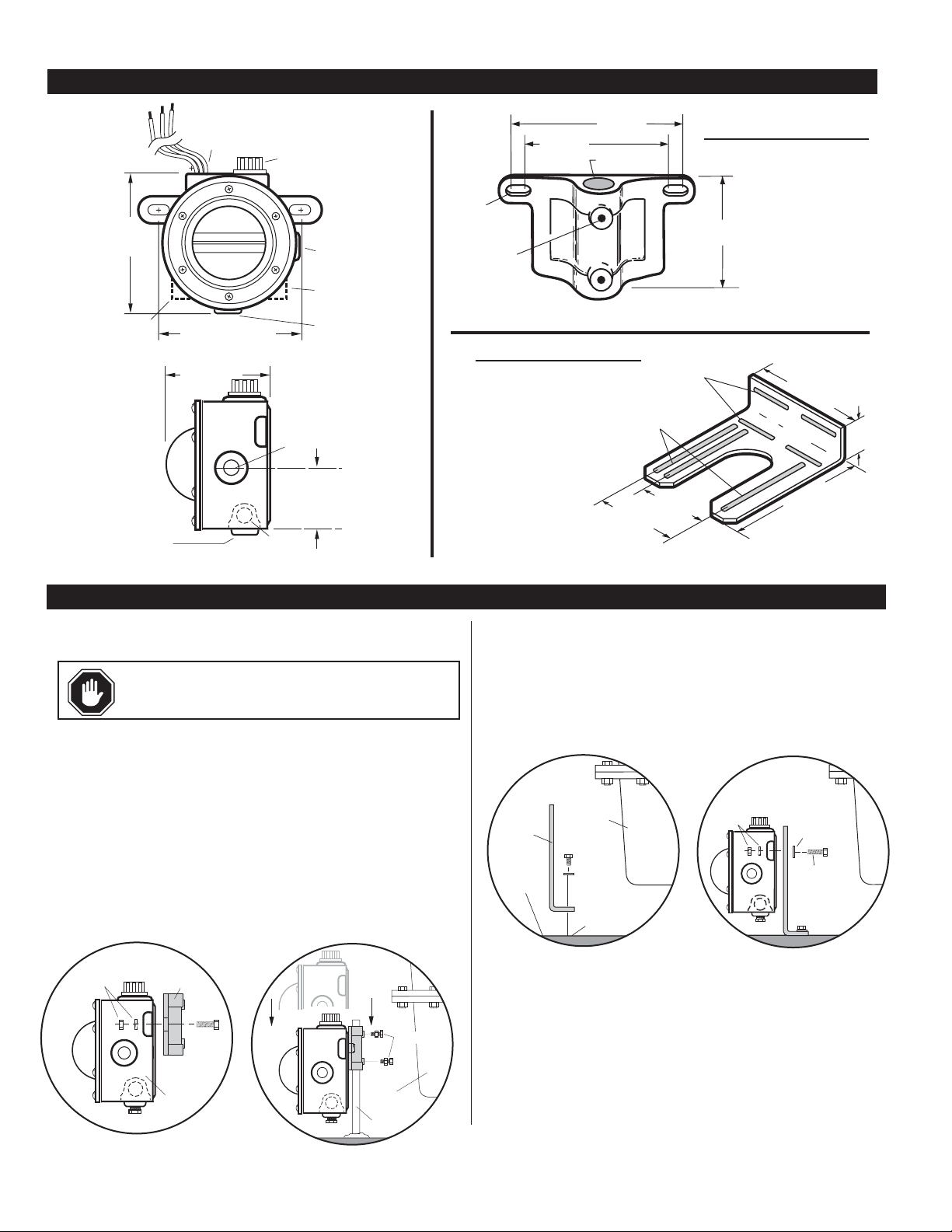
DIMENSIONS
LM2000
Mounting the LM2000
NOTE: Mount the LM2000 as close as possible to the crankcase.
The following instructions are based on the usage of the pipe and universal
mounting brackets shown above.
Pipe Bracket Mounting (15000238)
1. Mount a nominal 1/2 inch (13 mm) diameter pipe to the base of the engine.
2. Install the pipe bracket to the LM2000 using two 1/4-20 UNC x 1 inch
bolts, nuts and lock washers supplied. See Figure 1A.
3. Slip the LM2000 onto the pipe and install the two adjustment bolts. Each
bolt consists of a 1/4-20 UNC x 1 in. bolt, nuts and lock washers. See
Figure 1B. DO NOT tighten the adjustment screws too tightly because
you will have to adjust the LM2000 later in the installation process.
Mounting with Universal Bracket (15000370)
The universal bracket has two mounting methods: base mounting or
pan mounting.
Base Mounting
1. Install the universal bracket to the base as shown in Figure 2A using two
flat washers and two 5/16 inch dia. bolts or others as necessary.
2. Mount the LM2000 to the universal bracket using two 1/4-20 UNC x 1-
1/4 inch (32 mm) bolts, nuts and lock washers supplied (Figure 2B).
DO NOT tighten the adjustment screws too tightly. You will have to
adjust the LM2000 later in the installation process.
Figure 1B
LM2000
Pipe
Bracket
Lock Washer
and Nut
Bolt
Pipe
Crankcase
Adjustment
Bolts
Figure 1A
Figure 2B
Crankcase
Base
Universal
Bracket
Threaded
hole
Adjustment
Bolts
Flat
Washer
Lock Washer
and Nut
Figure 2A
15000238
Pipe Bracket Kit
15010224
Universal Flange Kit
Additional Hardware
Supplied
(2) 1/4-20 x 7/8 inch
(22 mm) screws
(2) 1/4-20 x 1 inch
(25 mm) screws
(4) 1/4-20 hex nuts
(4) 1/4 inch (6 mm) dia.
split washer
Additional Hardware
Supplied
(2) 1/4-20 x 1/4 inch
(32 mm) bolts
(4) 1/4 inch dia. flat washer
(2) 1/4-20 hex nuts
(2) 5/16-18 x 1/4 inch
(32 mm) bolts
(4) 5/16 dia. flat washer
(2) 5/16-18 hex nuts
CAUTION:
Excessive vibration can cause over-
fill. Be sure mounting brackets are supported.
4-5/8 in.
(117 mm)
3/8 NPTF
LM2000S
Oil Outlet
Connection
3/4 NPTF
1/2 in. Electrical
Female Conduit
Connection
4-1/2 to 5-3/16 in.
(114 to 132 mm)
2-7/8 in.
(73 mm)
3/8 NPTF
LM2000S
Crankcase
Balance Vent
1/2 NPTF
Oil Inlet
Connection
1/2 NPTF
3/8 NPTF
LM2000S
Oil Outlet
Connection
3/4 NPTF
Oil Inlet
Connection
1/2 NPTF
C
L
2-1/4 in.
(57 mm)
4-1/2 in.
(114 mm)
9/32 x 5/8 in.
(7 x 16 mm)
2 places
1/4-20 NC
2 places
5-3/16 in.
(132 mm)
Hole 7/8 in.
(22 mm) dia.
Slot, 29/64 in. (14 mm)
x 2-3/8 in. (60 mm)
4 places
Slot, 29/64 in. (14 mm)
x 4-3/8 in. (111 mm)
3 places
4-1/2 in.
(114 mm)
5-3/16 in.
(132 mm)
2-1/2 in.
(63.5 mm)
6-11/16 in.
(170 mm)
1-3/4 in.
(44 mm)
7-1/2 in.
(191 mm)
Page 3

Crankcase (Oil Pan) Mounting
1. Install the universal bracket to the crankcase using the existing crankcase bolts
(Figure 3A). Crankcase bolt diameter must be no larger than 7/16 inch (11 mm).
NOTE: Check clearance between crankcase and mounting bracket
before installing the mounting bracket. If space between the crankcase
and mounting bracket does not allow installation and access to the
adjustment bolts advance to Step 3.
2. Mount the LM2000 to the universal bracket using two 1/4-20 UNC x 1-
1/4 inch bolts, nuts and lock washers supplied. DO NOT tighten the
adjustment bolts too tight. You will have to adjust the LM2000 later in the
installation process.
3. If space between the crankcase and mounting bracket is narrow, install the uni-
versal mounting bracket to the LM2000 before installing to the crankcase oil pan.
Connecting Fittings and Hoses
The following instructions are based on the Murphy optional hose kit
described on page 1. If you did not order the optional hose kit, use the
list designation as a guide to the required materials.
1. Install the LM2000 fittings in their proper locations. NOTE: Apply a
sealant such as Teflon®, to all threaded
connections.
2. Attach the 1 inch (25 mm) diam-
eter, flexible monitoring hose
to the crankcase and the monitoring port on the LM2000.
See Figure 4. CAUTION:
The hose must slope slightly
downward from the LM2000
and MUST NOT have any
droops or low spots.
NOTE: If the drain plug on the
crankcase is used for the connection, we
recommend installation of a tee to allow
draining of the crankcase for service.
3. Install the 1/2 inch (13 mm) I.D. x 3 ft. (914 mm) hose to the vent connec-
tion on the LM2000 and to the vent connection on the crankcase. See
Figure 4. The vent connection on the crankcase must be well above
the regulated oil level. All hoses must be clear of obstructions, valleys,
or dips that could create liquid traps, or gas/air pockets. The vent and
crankcase connections should be as straight as possible.
BEFORE CONTINUING, VERIFY THAT ALL HOSE CLAMPS ARE TIGHT.
4. Fill the crankcase to the proper oil level. With the engine running and
warm, loosen the mounting bracket adjustment bolts and adjust the
LM2000 so that the oil level in the sight gauge is aligned with the white
“index line” on the dial (Figure 4). Tighten the adjustment bolts securely.
Connecting the LM2000 to an Oil Supply Tank
1. Remove the plug from the oil inlet connection. Be sure the removable screen,
inside the connection, is clear of debris. Install the oil inlet connection.
2. Connect a 1/2 inch I.D. (13 mm) or larger hose
to the oil inlet fitting on the LM2000 and to the
shutoff valve on the oil supply tank. See
Figure 5. Recommended minimum
height above the LM2000 is 2 ft.
(0.6m); maximum 25 ft.
(7.7m). The hose must
maintain a downward
slope and not have low
spots or droops.
Maximum head pressure
rating is 9.50 psi or 25 ft
oil (head pressure).
3. Before filling the supply
tank with oil, be sure the
tank is clean and dry and
the shutoff valve is closed.
Also, be sure all hoses and clamps are tight. Fill the tank with CLEAN
oil.
4. After oil supply tank is full, open the shutoff valve.
Next, make the proper electrical connections for the application.
(See Snap-switch ratings and schematic on page 1.)
Switch Test
To test the shutdown or alarm functions perform the following:
NOTE: Installations with closed vent systems can only be tested with
the engine off.
1. Unscrew the vent fittings.
2. Using a long narrow shank screw driver, gently insert until contact is
felt with float arm. Gently push the float arm down.
3. Verify proper switch operation
LM-00011N page 3 of 4
TYPICAL INSTALLATION
Figure 3B
Crankcase
Universal
Bracket
Crankcase
Bolt
Note Clearance
before mounting
Adjustment
Bolt
Flat
Washer
Lock washer
and Nut
Figure 3A
Oil Inlet
Hose
Oil Supply
Tank
Figure 5
Viewing
Lens
Monitoring Hose
Crankcase
Oil Level
Running
Engine
Vent
Hose
Oil Inlet
Hose
Figure 4
WARNING: Overfill condition can be caused by excessive
inlet pressure and/or improper “vent to crankcase” installation.
Page 4

OPERATING RANGE OF THE SNAP-SWITCH
LM2000 Typical Installation Shown with FSV Series Valves
Figure 6
Figure 6 shows the LM2000 dial and the operating range of the switch.
If level is within the designated zones the switch will activate.
The switch activates approximately 1/4 in. (6 mm) from the bottom of the
low zone. The dial in Figure 6 shows that if level continues to drop into
the low-low zone, a shutdown will occur.
NOTE: Color zones on dial face show approximate normal operating
zones. Actual conditions may vary depending upon operating characteristics of the engine. Placement of the LM2000 according to the above
instructions will compensate for these conditions.
Warranty
A limited warranty on materials and workmanship is given with this FW Murphy product.
A copy of the warranty may be viewed or printed by going to www
.fwmurphy.com/support/warranty.htm
WARNING:
Perform this installation using appropriate
protection. Trapped air and hot oil may cause burns.
LM2000 Typical Installation
LM-00011N page 4 of 4
CONTROL SYSTEMS & SERVICES DIVISION
P.O. Box 1819; Rosenberg, Texas 77471; USA
+1 281 633 4500 fax +1 281 633 4588
e-mail sales@fwmurphy.com
MURPHY DE MEXICO, S.A. DE C.V.
Blvd. Antonio Rocha Cordero 300, Fracción del Aguaje
San Luis Potosí, S.L.P.; México 78384
+52 444 8206264 fax +52 444 8206336
Villahermosa Office +52 993 3162117
e-mail ventas@murphymex.com.mx
www.murphymex.com.mx
FRANK W. MURPHY, LTD.
Church Rd.; Laverstock, Salisbury SP1 1QZ; U.K.
+44 1722 410055 fax +44 1722 410088
e-mail sales@fwmurphy.co.uk
www.fwmurphy.co.uk
MURPHY SWITCH OF CALIFORNIA
41343 12th Street West
Palmdale, California 93551-1442; USA
+1 661 272 4700 fax +1 661 947 7570
e-mail sales@murphyswitch.com
www.murphyswitch.com
In order to consistently bring you the highest quality, full featured products, we reserve the right to change our specifications and designs at any time.
MACQUARRIE CORPORATION
1620 Hume Highway
Campbellfield, Vic 3061; Australia
+61 3 9358 5555 fax +61 3 9358 5558
e-mail murphy@macquarrie.com.au
FW Murphy
P.O. Box 470248
Tulsa, Oklahoma 74147 USA
+1 918 317 4100
fax +1 918 317 4266
e-mail sales@fwmurphy.com
www.fwmurphy.com
R
E
G
I
S
T
E
R
E
D
USA–ISO 9001:2000 FM 28221
UK–ISO 9001:2000 FM 29422
Printed in U.S.A.
CRANKCASE
Electrical Conduit
wire to switch circuits
Oil Outlet
For vented crankcase use the
plastic vent plug or optional
vent tube kit (15000954).
For sealed systems, vent must be
piped back to crankcase,
above oil level.
LM2000
Oil Level Maintainer
Oil
Inlet
CLEAN Oil Supply Tank.
Height above LM recommended
2 ft. (0.6m) minimum and 25 ft
(7.7m) maximum.
Shutoff
Valve
Approx. Normal levels
in feet of head.
25’
Normal
10’
3/4 in.
(19 mm)
1/4 in.
(6 mm)
Operating Range
4’
Low Zone
Shutdown
 Loading...