

Page 1
Description
The L129 Series Lube Level Swichgage instrument is a combination lube level indicating gauge with adjustable low and
high limit switches. It provides protection against low oil level or high level
caused by overfill or fuel or water seepage into the crankcase. A 6-3/4 inch
(171 mm) deep sight gauge allows you to check the condition and level of
your oil without shutting down the equipment.
Fingertip adjustable limit switch contacts are adjustable thru 4-7/8 inch (122
mm) range. When the float touches the high or low limit contact, a normally open circuit will close which can activate alarms and/or shutdown the
equipment.
There are two models in the L129 Series: L129 and L129CK1. The L129
model is designed for grounded, low voltage electrical systems. It features a
one-wire-to-ground electrical circuit. The L129CK1 is designed for applications requiring a three-wire, above ground electrical circuit. It features
ungrounded contacts and a conduit hub for electrical wiring connection.
Specifications
Case: Die Cast Aluminum.
Lens: Tempered Glass.
Maximum Working Pressure: 10 psi (68.9 kPa) [0.69 bar].
Process Connection: 1/2 NPT.
Float Material: Brass.
Contact Rating: 2 A @ 30 VAC/DC, pilot duty.
Flow Restrictor Plug
Order Separately
Flow Restrictor Plug restricts oil flow between the
crankcase and the L129 Series. It is typically used on
some mobile applications such as marine and mobile
equipment. Part no. 15050241.
Installation Instructions for
L129 Series Level Swichgage
®
instrument
L-95006N
Revised 06-06
Section 15
00-02-0174
Please read the following information before installing. A visual inspection of this product for
damage during shipping is recommended before mounting.
GENERAL INFORMATION
BEFORE BEGINNING INSTALLATION OF THIS MURPHY PRODUCT
✔✔
Disconnect all electrical power to the machine.
✔✔
Make sure the machine cannot operate during installation.
✔✔
Follow all safety warnings of the machine manufacturer.
✔✔
Read and follow all installation instructions.
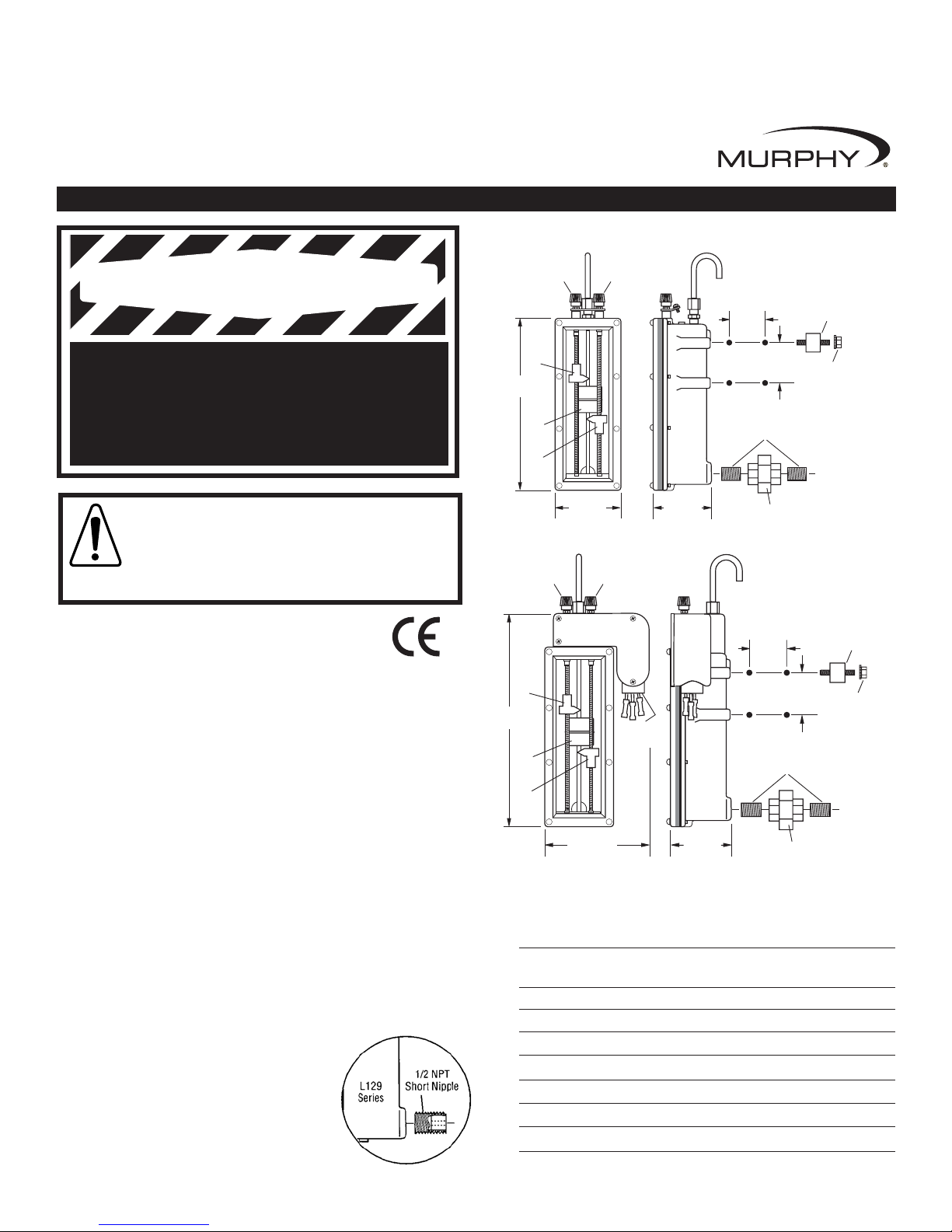
L129CK1
Dimensions
*
L129
CAUTION:
Certain danger to human and to equipment
such as applied in a mobile or marine application may occur if
some equipment is stopped without pre-warning. It is therefore,
recommended that monitored functions be limited to alarm
only or to alarm before shutdown in such applications.
Repair Kits
Specify part number.
L129
15000888 Full Repair Kit (less castings and glass assÕy) fo r date
code T2 and later.
15000480 Bezel, Glass and Gasket Set for date code W7 and later
15000485 Glass and Gasket Set for all date codes
15050241 Restrictor plug for all date codes
L129CK1
15000480 Bezel, Glass and Gasket Set for date code W7 and later
15000485 Glass and Gasket Set for all date codes
15050241 Restrictor plug for all date codes
L-95006N page 1 of 2
*Complete with EMC Council directive 89/336/EEC regarding electromagnetic compatibility.
High Level
Adjust
Low Level
Adjust
WARNING
-
-
-
-
Adjust
2-31/64 in.
(63 mm)
++
High
Contact
++
8 in.
(203 mm)
Float
++
Low
Contact
++
3-3/16 in.
(81 mm)
High Level
Adjust
Low Level
1-1/2 in.
(38 mm)
2 in.
(51 mm)
1/2 NPT Closed Nipple
(2 supplied)
1/2 NPT Union
(1 supplied)
Shock Mount
(2 supplied)
Keps nut
(2 supplied)
High
Contact
9-55/64 in.
(250 mm)
Float
Low
Contact
+ +
+ +
+ +
+
4-55/64 in.
(123 mm)
+
1/2 NPT
Conduit
-
-
-
-
2-31/64 in.
(63 mm)
1-1/2 in.
(38 mm)
2 in.
(51 mm)
1/2 NPT Closed Nipple
(2 supplied)
1/2 NPT Union
(1 supplied)
Shock Mount
(2 supplied)
Keps nut
(2 supplied)
Page 2
INSTALLATION and OPERATION
NOTE: Read all instructions before beginning installation.
Mounting
1.
Determine which side of the engine to mount the L129. This will normally be the
side of the engine from which it is started. Weld a slotted mounting plate to the
engine skid or attach the mounting plate to the crankcase. If a mounting plate is
not used, a support strap is recommended (see Typical Installation below).
2.
Install the shockmounts in the threaded holes provided in the mounting bosses on
the rear of the L129. NOTE: We recommend using the shockmounts provided
to minimize “contact bounce” resulting in improper operation.
3.
Attach the L129 to the mounting plate as shown below but do not tighten TOO
TIGHT since you will have to adjust the L129 later in the installation process.
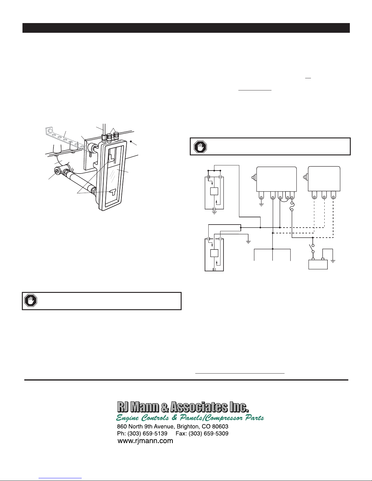
Typical Installation
Crankcase
Tee
Customer Supplied
Support Strap
Shockmount
High and Low
Contacts
Vent
Contact Adjustment Knobs
Mounting
Plate
Sight
Glass
L129 vent back to the crankcase. If you do not do this, the L129 will indicate
high level with a pressurized crankcase and a low level with a vacuum crankcase.
In extreme cases a pressurized system will blow oil out the vent tube or in vacuum crankcases can suck oil out of the L129.
To vent the L129 back to the crankcase, install a 1/4 inch (6 mm) O.D.
or larger tubing (copper or flexible) from the L129 vent fitting to a point in the
crankcase above the full oil level or in the fill pipe that is not
restricted by baffles, filters or other obstructions. If connecting directly into the crankcase, be
sure the entry point is clear of oil splash
4.
Refill the crankcase to proper oil level. With the engine running and warm, loosen
that can plug the tube opening.
the L129 from the mounting bracket and adjust the L129 so that the oil level shows
approximately midway or above in the sight glass. Tighten shockmount nuts.
Wiring
Follow appropriate wiring for the alarm or engine shutdown system you are using.
Diagrams below are shown with the float in the “full” position.
CAUTION:
disconnected. Observe all contact ratings and voltages.
HI LOW
perform all wiring connections with the battery
Magnetic Switches
117PH
C S
L129
518PH
G NC
SW1 SW2
B
B
Connecting Hoses and Fittings
1.
DRAIN THE CRANKCASE. If the crankcase does not have an auxiliary plug or
connection, connect the L129 to the crankcase drain plug connection. This connection will n
fiber washer. NOTE: If the drain plug on the crankcase is used for the connection,
we recommend installation of a tee to allow draining of the crankcase for service.
2.
Flexible hose or rigid pipe can be used to attach the L129 to the engine
crankcase. Flexible hose is to be 1/2 in. (13 mm) I.D. minimum and made of
quality material. Use of flexible hose will allow you to adjust the height of the
L129 to properly reflect the oil level in the crankcase. Also, a swivel connection
on one end of the hose will assist in properly aligning the L129.
Rigid pipe is to be 1/2 inch pipe. If the length of the pipe is relatively short, no
additional support for the L129
pipe union is provided in the installation kit.
Attach the hose or pipe from the L129 process connection (1/2 NPT) to the
crankcase.
3.
For vented crankcases, install the tube fitting and copper cane provided in the
installation kit into the top of the L129. Venting to atmosphere will allow the oil
level to rise in the L129 to the same level as in the crankcase, (the pressure/vacuum in the L129 and the crankcase must be equal). If the crankcase develops a
positive (pressure) or negative (vacuum) pressure, you MUST connect the
ormally be a straight (parallel) thread which seals with a copper or
WARNING: If both flexible hose and shockmounts are used, a
gr ound wi r e must be added between the L129 and the engine.
may be needed, although it is recommended. A
HI
BLACK
LOW
RED
WHITE
COM.
L129CK1
_
Rack Pull
Solenoid
Fuel
Valve
Ignition
Coil
+
Battery
Contact Rating: 2 A @ 30 VAC/DC, pilot duty.
Operation Test
The following test is to be performed after the L129 has been installed and the
crankcase has been filled to the proper oil level.
1.
With equipment running, turn the high and low adjust knobs one at a time until
they “make” contact with the float. When contact is made the alarm or shutdown
circuit should actuate.
2.
Return high and low adjustment knobs to the proper contact position before
operating equipment.
Warranty
A limited warranty on materials and workmanship is given with this FW
Murphy product. A copy of the warranty may be viewed or printed by going
to www.fwmurphy.com/support/warranty.htm
L-95006N page 2 of 2
 Loading...