

Page 1
00-02-0172 page 1 of 2
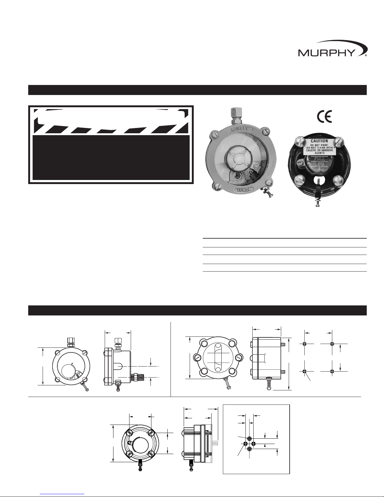
Description
The L100, L100W series are general purpose level Swichgage instruments
designed for small engines and pumps. They connect to the crankcase
through a 1/4 NPT pipe nipple and/or 1/2 NPT fittings.
The L120, L127 and L128 series Lube Level Swichgage instruments are
designed for specific engines and mount directly to the machined surface on
the crankcase.
■
L120 Series fits engines previously manufactured by Witte Engine Works,
Lufkin Industries and now manufactured by Arrow Speciality Company.
■
L127 Series fits Fairbanks-Morse ZC series engines, Bell Manufacturing,
and similar engines.
■
L128 Series fits Arrow Speciality engines and the Climax/Continental
Emsco series.
Specifications
Float Actuated Oil Level Swichgage®instrument
Installation Instructions
Models L100, L100W, L120, L127, and L128
00-02-0172
Revised 03-07
Section 15
Read the following information before installing. A visual inspection of this product for damage during shipping is recommended
before mounting. These installation instructions are intended for all L100, L120, L127, and L128 Series models.
GENERAL INFORMATION
L100
DIMENSIONS
L120
2-1/8 in.
(54 mm)
4-5/16 in.
(110 mm)
3-3/8 in.
(86 mm)
2-7/32 in.
(56 mm)
Mounting Holes 4 places,
5/16 in. (8 mm) diameter
2-7/32 in.
(56 mm)
L127 and L128
L100 and L100W
2-3/4 in.
(70 mm)
2 in.
* *
(51 mm)
2-1/2 in.*
(64 mm)
2-15/64 in.
(57 mm)
Mounting
**
holes 4 places
5/16 in. (8 mm)
diameter
2-15/64 in.
(57 mm)
** Applies to L127 only
* Applies to L128 only
47/64 in.
(19 mm)
3/8 in.
(10 mm)
17/32 in.
(13 mm)
1-17/32 in.
(39 mm)
Mounting
holes 2 places
5/16 in. (8 mm)
Oil inlet
holes
L128 Mounting Dimensions
C
L
27/32 in.
(21 mm)
3-1/8 in.
(79 mm)
2-1/8 in.
(54 mm)
BEFORE BEGINNING INSTALLATION OF THIS MURPHY PRODUCT
✔✔
Disconnect all electrical power to the machine.
✔✔
Make sure the machine cannot operate during installation.
✔✔
Follow all safety warnings of the machine manufacturer.
✔✔
Read and follow all installation instructions.
Contact
Rating Case Float Gasket
L100/L100W 2A 30 V Aluminum Brass Neo-Cork
L120 2A 30 V Aluminum Brass Buna-N
L127 2A 30 V Nylon Brass Buna-N
L128 2A 30 V Nylon Brass Neo-Cork
L127/L128
†
† Products covered by this literature comply with EMC Council directive 89/336/EEC
regarding electromagnetic compatibility except as noted.
WARNING
Page 2

00-02-0172 page 2 of 2
Warranty
A limited warranty on materials and workmanship is given with this FW Murphy product.
A copy of the warranty may be viewed or printed by going to www.fwmurphy.com/support/warranty.htm
INSTALLATION
TYPICAL WIRING DIAGRAM
The oil level Swichgage instrument can be connected to a Murphy magnetic
switch or magneto. Switch contact rating is 2 A @ 30 VAC/DC resistive,
circuit closes to ground.
Models L100, L100W
1. Install the pipe fittings into the crankcase drain or other fitting in the bottom
of the crankcase. Use Teflon tape or non-hardening thread sealant. A tee
should be installed so that it can be used as the crankcase drain. Be sure to
install a pipe plug in the open side of the tee.
2. For crankcases vented to atmosphere, install the l/4 in. (6 mm) tube fitting
and cane in the top of the L100/L100W. For non-atmospheric crankcases,
install the tube fitting and connect 1/4 in. (6 mm) copper tubing to a suitable fitting in the crankcase cavity above the normal operating and splash
level of the lubricant. Note that the tube must remain open at all times and
that it can be closed by oil splash. This will cause improper operation of
the lube level Swichgage instrument.
Models L120, L127
and L128
1. All mounting surfaces must be
clean of oil, grease, and dirt.
2. Be sure the mounting plate to
engine crankcase gasket is properly aligned with the bolt hole
and mounting plate hole patterns.
3. FOR THE L127, be sure that the
float grounding strap extends into
the crankcase cavity and fits tight against the crankcase.
4. Tighten mounting screws in a crisscross pattern. Do not overtighten the screws
as this may cause case or mounting plate distortion resulting in oil leakage.
All Models
1. Fill the crankcase with oil to the engine manufacturer’s specified
LOWEST level.
2. IMPORTANT: Adjust the low level contact screw so that the circuit
“makes” (check continuity with an Ohm meter). Contact is NOT factory set.
3. Fill the crankcase to “full” level and observe that the float has risen and no
longer “makes” with the low level contact. If the Swichgage instrument
also has a high level contact the float should NOT “make” with the high
level contact with normal oil level. Set the high level contact at an appropriate setting for a crankcase overfill condition.
4. Attach appropriate wiring to the engine shutdown or alarm system. Consult
appropriate Murphy or engine manufacturer’s wiring instructions. Typical
wiring is shown below.
5. Start the engine and verify that the oil level remains in a “safe” running
level and that there are no oil leaks. Allow the engine to warm up and
check that mounting screws are tight. CAUTION: Do not over tighten.
6. To check switch operation, open crankcase drain to allow oil level to drop until
the low level contact “makes” and shuts down the engine. Refill crankcase.
WARNING:
Disconnect all electrical power from the
equipment and disable the equipment so it cannot start
during the installation period.
CAUTION:
Perform the wiring operation with the power
source off. Observe all contact and voltage ratings.
CAUTIONS:
Do NOT paint L127 or L128.
Do NOT clean L127 or L128 with caustic or abrasive
solutions or compounds. Do NOT clean L127 or L128
with solvents. Clean ONLY with soap and water.
CONTROL SYSTEMS & SERVICES DIVISION
P.O. Box 1819
Rosenberg, Texas 77471 USA
Phone: +1 281 633 4500 Fax: +1 281 633 4588
E-mail: sales@fwmurphy.com
FRANK W. MURPHY, LTD
Church Rd Laverstock
Salisbury SP1 1QZ UK
Phone: +44 172 241 0055 Fax: +44 172 241 0088
E-mail: sales@fwmurphy.co.uk
Web site: www.fwmurphy.co.uk
COMPUTRONIC CONTROLS, LTD
41 - 43 Railway Terrace Nechells
Birmingham B7 5NG UK
Phone: +44 121 327 8500 Fax: +44 121 327 8501
E-mail: info@computroniccontrols.com
Web site: www.computroniccontrols.com
FW MURPHY INSTRUMENTS (HANGZHOU) CO. LTD
77 23rd Street
Hangzhou Economic & Technological Development Area
Hangzhou, Zhejiang 310018 China
Phone: +86 571 8788 6060 Fax: +86 571 8684 8878
FW MURPHY
P.O. Box 470248
Tulsa, Oklahoma 74147 USA
+1 918 317 4100 Fax: +1 918 317 4266
E-mail: sales@fwmurphy.com
INDUSTRIAL PANEL DIVISION
Fax: +1 918 317 4124
E-mail: ipdsales@fwmurphy.com
MURPHY POWER IGNITION
Web site: www.murphy-pi.com
www.fwmurphy.com
Printed in U.S.A.
L127 Mounting Screws
1/4-20 x 2 in. (51 mm)
4 Places
Engine
Block
Oil Port
Float
Ground
Strap
Machined
Surface
Float
Magneto
OR
Murphy Magnetic Switch
 Loading...