

Murphy iGUARD Installation And Operation Manual
Phase-out / Discontinued Product
Check Availability
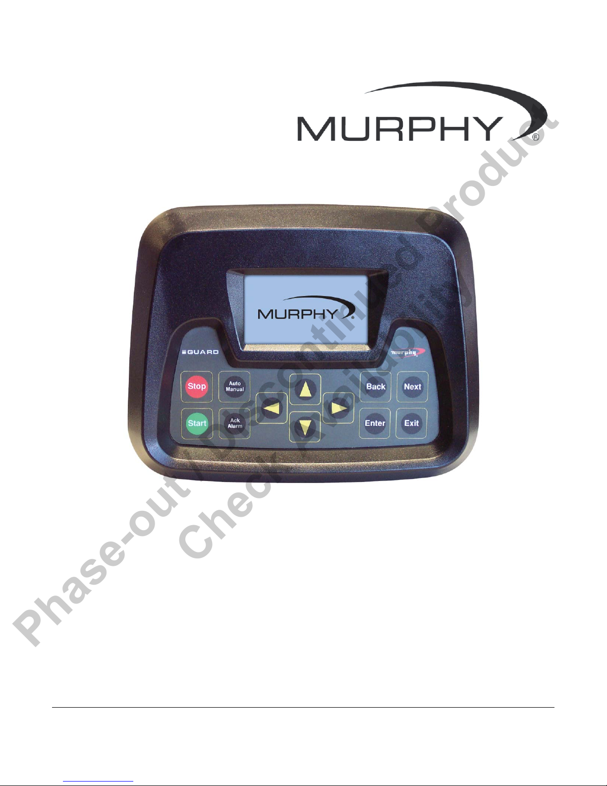
iGUARD
Digital Generator Set Controller
Installation and Operations Manual
00-02-0522
04-06-11
Section 75

Phase-out / Discontinued Product
Check Availability
In order to consistently bring you the highest quality, full featured products, we reserve the right to change our
specifications and designs at any time. The latest version of this manual can be found at www.fwmurphy.com.
Please read the following information before installing.
BEFORE BEGINNING INSTALLATION OF THIS MURPHY
PRODUCT:
Disconnect all electrical power to the machine.
Make sure the machine cannot operate during installation.
Follow all safety warnings of the machine manufacturer.
Read and follow all installation instructions.
Please contact FW MURPHY immediately if you have any
questions.

Phase-out / Discontinued Product
Check Availability
T able of Conte nt s
Introduction ............................................................................................................................. 1
Product Description ...................................................................................................... 1
User Interface and Navigation ...................................................................................... 1
iGUARD Operating Instructions ............................................................................................ 3
Operating Sequence .................................................................................................... 3
Programming the iGUARD from the Keypad ................................................................ 5
Settings and Definitions ......................................................................................................... 8
Operating Parameters .................................................................................................. 8
Communication Parameters ....................................................................................... 12
Miscellaneous Parameters ......................................................................................... 13
Engine Parameters .................................................................................................... 16
Generator Parameters ............................................................................................... 18
Digital Inputs and/or Relay Outputs ............................................................................ 21
Analog Inputs ........................................................................................................................ 30
Manufacturers Specifics ...................................................................................................... 36
iGUARD Typical Installation and Mounting ....................................................................... 38
iGUARD Electrical Installation ............................................................................................. 41
Electrical Hook up ...................................................................................................... 41
Energy Monitoring Board (EMB) ................................................................................ 45
Installing the Mimic/Annunciator DM/A .............................................................................. 50
DM/A Mimic/Annunciator Versions ............................................................................. 50
Specifications ........................................................................................................................ 58
Standard Components ............................................................................................... 58
iGUARD Options and Accessories ..................................................................................... 59

Phase-out / Discontinued Product
Check Availability
(THIS PAGE INTENTIONALLY LEFT BLANK)
Phase-out / Discontinued Product
Check Availability
Introduction
This document is designed to support a user in getting familiar with the iGUARD Digital
Generator Set Controller and how to navigate the interface, modify the settings and install and
operate the controller. Before attempting to set up the controller, be sure to read and
understand this manual in its entirety.
Product Description
Description
The iGUARD controller is a high performance, state of the art, digital generator set controller.
This robust controller features high-speed microprocessors, and high accuracy AC
measurements. The iGUARD is a menu driven system, organized by "stacks", with "substacks" where required. User connections are made via the plug in connectors on the rear of
the controller. The iGUARD controller has a textured finish; UV stabilized polycarbonate
injection molded housing, and is sealed with an “o” ring to help protect the iGUARD from the
environment. There is a back cover protecting the Energy monitoring Board (EMB) to prevent
contact with circuit board components and potentially harmful AC voltage wiring.
User Interface and Navigation
The keypad on the iGUARD is a capacitive touch sensing system. There are no mechanical
switches to wear or stick, and the technology has been time proven in many applications. It
operates in extreme temperatures, with gloves, through ice, snow, mud, grease, etc., and it
allows complete sealing of the front of the iGUARD. It does operate slightly differently than a
membrane keypad, in that there is no tactile feedback. The ‘key is pressed’ feedback is
provided by momentarily beeping the audible alarm. The keys on the keypad do the following
functions:
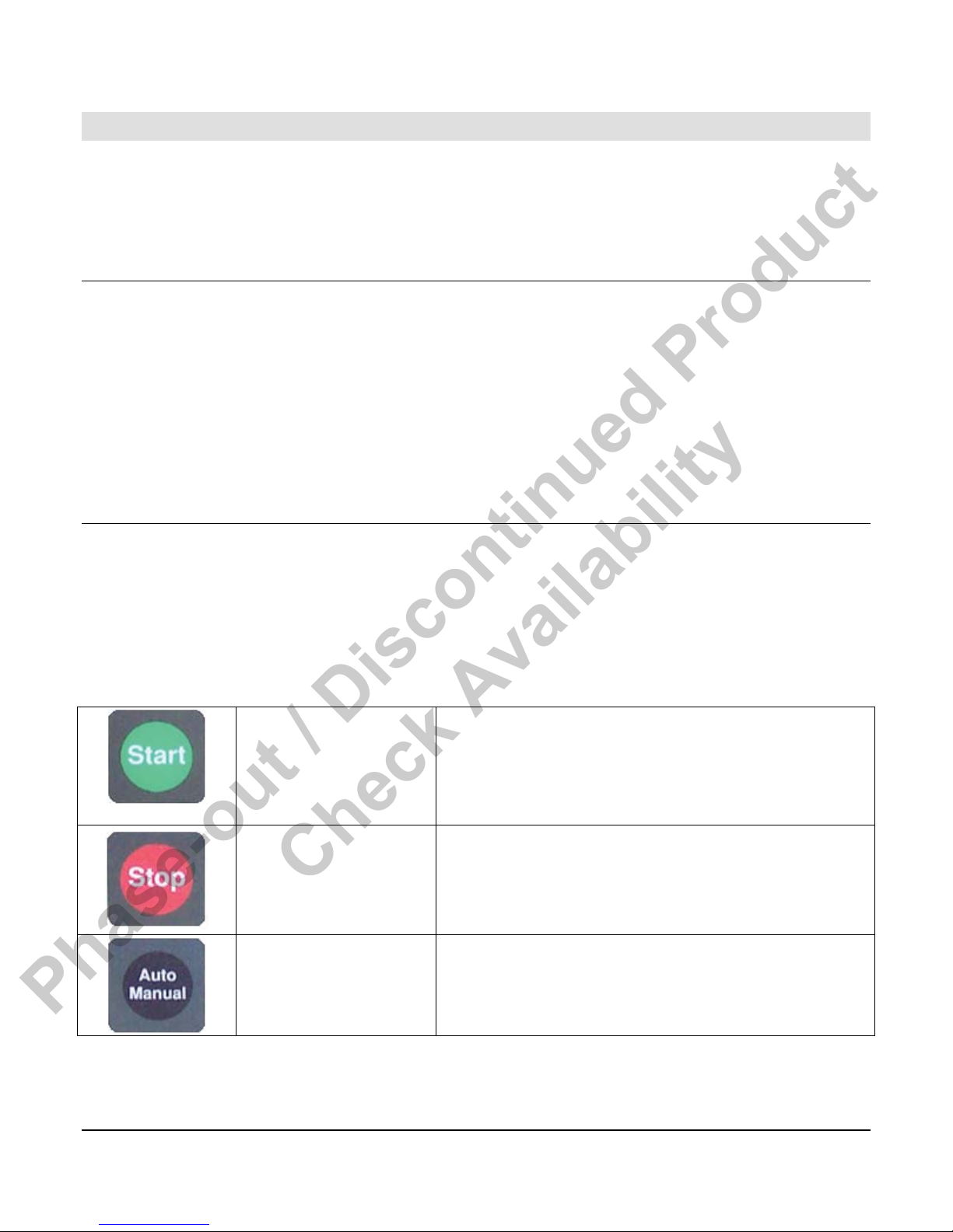
START
STOP
Auto/Manual
In Manual mode pressing the start pad will cause
the engine to start. In automatic mode the screen
will display an error message that system must be
in manual mode to start with the start button.
In automatic or manual mode pressing the stop pad
will stop the set. The system is forced into a
manual mode, and will not autostart until returned
to automatic mode.
Selects manual (sometimes-called local) operation
or automatic mode (system monitors a digital input
for a start signal).
Section 75 00-02-0522
04-06-11 - 1 -
Phase-out / Discontinued Product
Check Availability
Acknowledge/Alarm
Up / Down Arrows
Left / Right Arrows
Next
Back
For warnings that do not cause a shutdown,
pressing this pad will clear the alarms active at that
moment. If the conditions subsequently clear and
re-occur or if additional warnings occur, the
common alarm output will come back on.
In program mode scrolls the menu selections and
also scrolls through the choices for a given
parameter.
In normal operation steps forward/backward
through the screens available in the active
submenu
In normal operation steps forward through the main
menu selection
In normal operation steps backward through the
main menu selections.
Enter
Exit
In program mode, pressing Enter will allow a
variable to be changed, and then pressing Enter
again will accept the displayed /new value.
In normal operation returns the system to the main
(default) screen. In program mode cancels any
changes made unless the "Enter" pad has already
been pressed.
Section 75 00-02-0522
04-06-11 - 2 -
Phase-out / Discontinued Product
Check Availability
iGUARD Operating Instructions
Operating Sequence
The iGUARD controller, while reprogrammable, follows a standard operating sequence. This
operating sequence is basically a set of machine states that happen in a pre-determined order.
Machine states can be set to zero if not needed, or adjusted to fit the application. For the basic
operating sequence, see the iGUARD Sequence Appendix in the Installing the
Mimic/Annunciator DM/A section, this document. The iGUARD operating sequence includes
the following modes:
Ready to Start Mode
Prestart Delay Mode
Prelube Mode
Preheat
Cranking / Crank Rest Mode
Crank Disconnect / Engine
Running Mode
Warmup Mode
Automatic start mode ready for a contact closure to initiate an
automatic start and run sequence.
A timer used to prevent nuisance starts, or to warn nearby
personnel that automatic equipment is about to start (set to 0
to bypass).
In larger generators there may be a requirement for
automatic lubrication prior to cranking (set to 0 to bypass).
Timer set to provide the correct amount of precrank operation
of the air intake heaters used to facilitate starting in cold
conditions. (Set to 0 to bypass).
Engine is attempting to start and will go through the number
of selected starting attempts.
Engine speed is greater than the crank disconnect.
Timer to allow system to run unloaded for selected time (set
to 0 to bypass).
At Load Mode
Power Good Mode
Cooldown Mode
Section 75 00-02-0522
04-06-11 - 3 -
Generator is running at load.
This mode is to prevent nuisance start/stops. The controller
continues running but monitors the remote start contact while
in this mode. The power good timer must expire before the
system can proceed to cooldown. Any further call to run
resets the power good mode timer to its preset value.
Generator runs unloaded for a preset time.

Phase-out / Discontinued Product
Check Availability
Energized to Stop
Stopped Mode
Postlube Mode
The Energized to Stop timer is ON and the Energized to Stop
output is active.
Generator has come to a complete stop.
In larger generators there may be a requirement for
automatic lubrication after a normal start/run/stop cycle
before the engine can be restarted (set to 0 to bypass). After
postlube, the system returns to Ready to start. Additionally
there are two fault shutdown modes:
Shutdown / Lockout with Cooldown Mode - In
the case of some faults the controller will open the
"at load’ contact and then go through a normal
cooldown and stop sequence, but will not allow an
automatic restart without a system reset.
Immediate Shutdown/Lockout (no Cooldown)
Mode - Because of the severity of most faults, the
controller will cause an immediate
Shutdown/Lockout without a cooldown period, and
will not allow an automatic restart without a system
reset.
Shutdown / Lockout with
Cooldown Mode
Immediate
Shutdown/Lockout (no
Cooldown) Mode
In the case of some faults the controller will open the "at
load’ contact and then go through a normal cooldown and
stop sequence, but will not allow an automatic restart without
a system reset
Because of the severity of most faults, the controller will
cause an immediate Shutdown/Lockout without a cooldown
period, and will not allow an automatic restart without a
system reset.
Section 75 00-02-0522
04-06-11 - 4 -

Phase-out / Discontinued Product
Check Availability
Programming the iGUARD from the Keypad
The iGUARD controller can be programmed in two separate ways. Most setup can be done
from the front panel. There are some parameters, such as changing passwords that require
the use of the iGCON software tool. The iGUARD programming menus can be accessed at
any time by pressing the left and right arrows at the same time. This will bring up the password
menu:
The factory defaults (and what they allow access to) for the various levels of password are:
Access Security - Allows input of 4-character security code.
PASØ - No operational Access. It allows viewing of the data screens but
parameters cannot be edited.
PAS1 - Operational Access. It allows Manual Start and Stop but parameters
cannot be edited.
PAS2 - Parameter View Access. Allows for viewing of all parameters and
editing of the following parameter settings:
Change Language
Key Sensitivity Level
Back Light On/Off
Ack Maintenance Timers
Enable Beeper
Select Pressure Units
Select Temperature Units
Modify Date
Edit Clock Start and Stop Timers
PAS3 - Parameter Edit Access. Allows for viewing and parameter editing
but does not allow calibration of AC.
PAS4 - Calibration Access. Allows calibration of the AC parameters.
PAS5 - kW Limit Edit and Config Select Access. Allows editing of kW limits
and various communication addresses.
Section 75 00-02-0522
04-06-11 - 5 -
Phase-out / Discontinued Product
Check Availability
What to do if you lose your Password
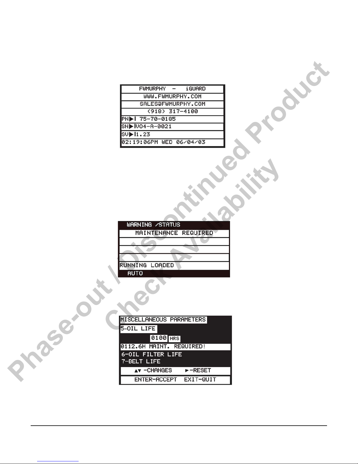
Press NEXT until you see the screen with a graphic display of the Murphy logo. Press NEXT
once to go to the system information screen.
Write down the serial number, the current date, and time showing on the real time clock
display, and contact us (918) 317-4100, ask for technical support). We will provide a temporary
password that will allow you to access the system to recover the passwords.
Acknowledging Maintenance Timers
Status/ Warning Screen - You may see this warning/status message:
This is information that one or more of your maintenance reminder timers has expired. To
acknowledge the warning and reset the timer, enter the programming mode, and go to the
Miscellaneous Parameters screen.
Section 75 00-02-0522
04-06-11 - 6 -
Phase-out / Discontinued Product
Check Availability
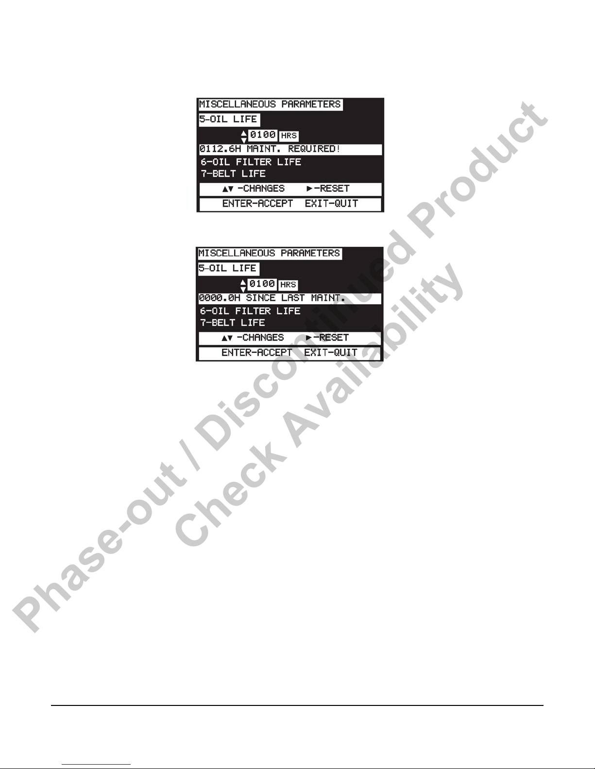
Press Enter and the screen should change to this display with the number quantity flashing:
Press the right arrow to reset and the display should change to:
Each timer can be acknowledged as it expires, or whenever the maintenance is done, if it
precedes the timer reaching 0.
Displaying Data
Use the Auto scroll function.
To turn the Auto scroll function ON, press the ENTER and NEXT keys at the same time. There
are three Auto scrolling speeds temporarily displayed on the top line each time ENTER and
NEXT keys are pressed (4 seconds, 8 seconds, 12 seconds). To select a different speed,
simultaneously press the ENTER and NEXT keys again to go to the next speed section. To
turn off the Auto scroll function press the EXIT and NEXT keys at the same time. If the
iGUARD is left on a non-scroll screen (like the Warnings/status screen) it will display only the
Warning/status screen.
When Programming
Touching the left arrow takes you immediately to the “TOP” of the program selection list.
The right arrow takes you immediately to the “BOTTOM” of the selection list.
Section 75 00-02-0522
04-06-11 - 7 -
Phase-out / Discontinued Product
Check Availability
Settings and Definitions
Operating Parameters
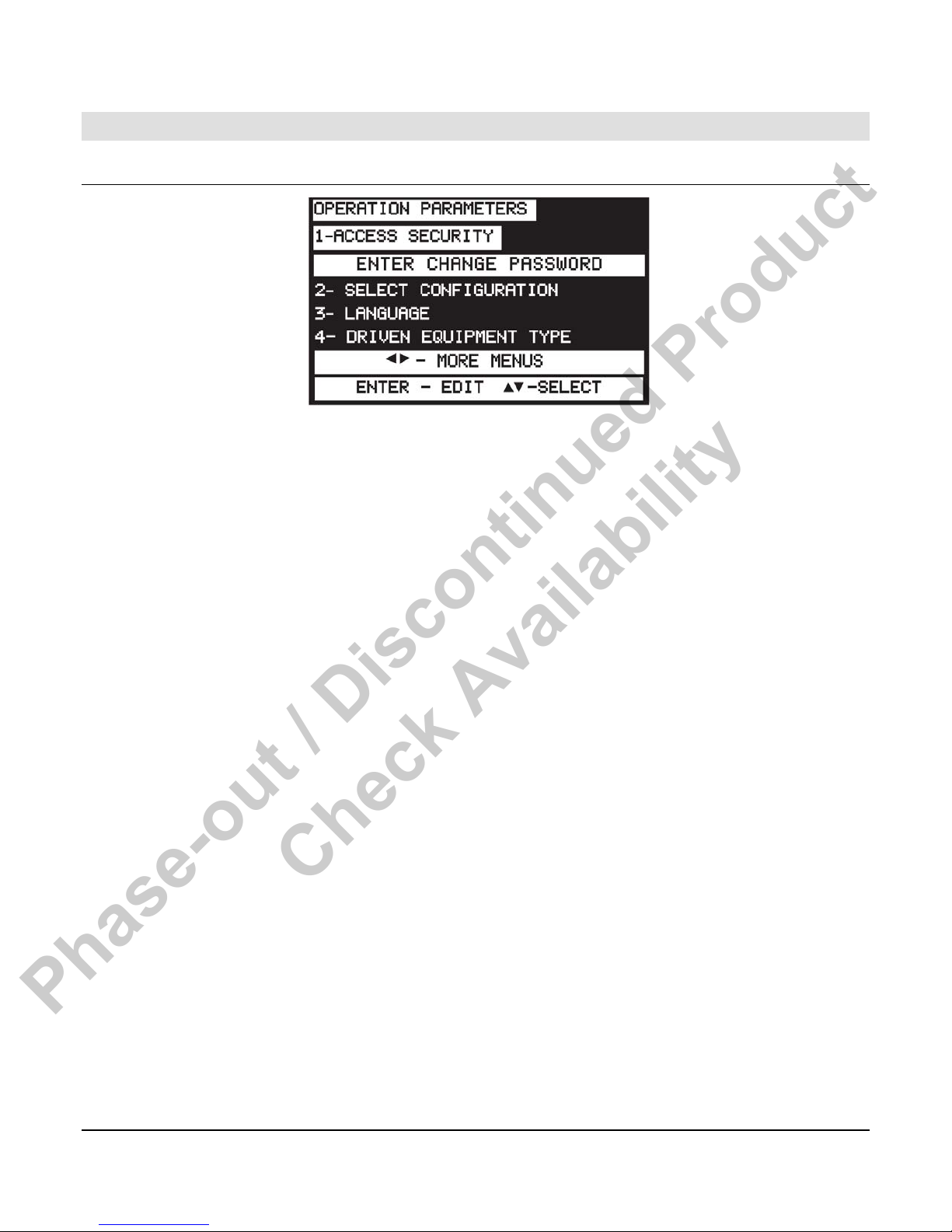
To bring up the iGUARD Programming Screen, press the Left and Right arrow keys
simultaneously. After gaining access to this screen, you can use the Left, Right, Up and Down
keys to navigate from column to column and to adjust the values or change characters
displayed. Press Enter when password is correct.
The security level is shown on the bottom of the display. Press Exit to bring up the Parameters
screen.
1. Access Security - Allows input of 4-character security code.
Level - No operational Access. It allows viewing of the data screens but
parameters cannot be viewed or edited.
Level 1 - Operational Access. It allows Manual Start and Stop but
parameters cannot be viewed or edited.
Level 2 - Parameter View Access. Allows for viewing of all parameters and
editing of the following parameter settings:
Change Language
Key Sensitivity Level
Back Light On/Off
Ack Maintenance Timers
Enable Beeper
Select Pressure Units
Select Temperature Units
Select Temperature Units
Date Display Format
Modify Date
Edit Clock Start and Stop Timers
Section 75 00-02-0522
04-06-11 - 8 -

Phase-out / Discontinued Product
Check Availability
Level 3 - Parameter Edit Access. Allows for viewing and parameter editing
but does not allow calibration of AC.
Level 4 - Calibration Access. Allows calibration of AC parameters.
Level 5 - kW Limit Edit and Config Select Access. Allows editing of kW
limits and various communication addresses.
2. Language - Allows selection of language used to display text.
a. English (Default)
b. Spanish
c. etc. (future expansion)
3. Driven Equipment Type - Allows selection of type of equipment that is driven by the
engine.
a. None (engine only, ignores all AC parameters)
b. AC Alternator (Genset) (Default)
4. Key Sensitivity Level - Determines how sensitive the touch pad keys are for your
application.
a. Low*
b. Normal (Default)
c. High
5. Default Screen - When the system is running this selects the screen that will show.
Event History
Warnings / Status
Engine / Gen Status
Meters
Nominal Meter
Splash Screen
Information
NOTE: * Newer versions of the controller/software will not have a “LOW”
sensitive selection.
6. Lamp Test - Tests LCD.
7. LCD Backlight - Turns the iGUARD display backlight off, unless an error condition
activates the common visual alarm.
a. Disabled
b. Enabled (Default)
8. Guard Beeper - Keypress indication and/or audible warning buzzer.
Section 75 00-02-0522
04-06-11 - 9 -
Phase-out / Discontinued Product
Check Availability
a. Disabled
b. Enabled - Beeps with each keypress, sounds for errors. (Default).
9. Pressure Units - User selection of display units.
a. PSI (Default)
b. kPa
c. bar
10. Temperature Units - User selection of display units.
a. Fahrenheit (Default)
b. Celsius
11. Date Display - Format Selectable.
a. American Style (Default)
b. European Style
12. Event Types to record.
a. All events (Default)
b. Shutdown events only
13. Clear Event History - Erases all stored history events.
14. Standby Mode Timer - When the timer expires, the system goes into a lower power
standby mode. After it times out the LCD screen changes to a text message, the blue LCD
backlight is turned off, and the Energy Monitoring board is de-powered. Any keypress or a
remote call to run wakes the unit up. Value can be set between 30 seconds and 59 minutes 30
seconds or can be set to OFF.
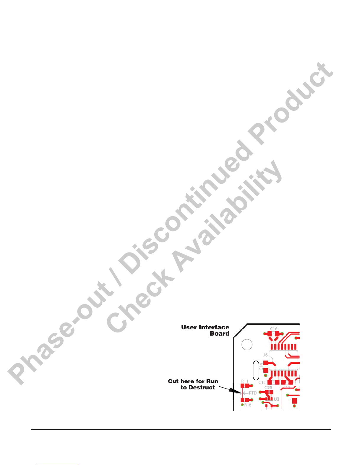
15. Run to Destruct - When run to destruct is enabled, the system will only sound alarms for
errors, instead of shutting down. Since this could lead to the destruction of the equipment or
the load, there is both a menu selection and a jumper that must be physically cut (see
schematic diagram), making this a deliberate choice.
a. Disabled (Default)
b. Enabled
16. Edit Time and Date - Allows user to adjust
Section 75 00-02-0522
04-06-11 - 10 -

Phase-out / Discontinued Product
Check Availability
time and date of iGUARD.
17. Input - Output Test - Shows the status of the analog inputs, digital inputs, and relay
outputs.
a. The analog input screen shows any change in the inputs. For example
if the resistance value of a resistive sender changes, the counts will
change.
i. Analog channel number
ii. Name/setup label
iii. Actual value
b. The digital input screen shows the status of the digital inputs.
i. Digital Input Number
ii. Name/setup label
iii. Made/open
c. Relay output status allows the forcing of any relay out. The screen
shows:
i. Relay output number
ii. Name/setup label
iii. State
NOTE: Analog values, digital input, and relay status may be read on these
screens at any time. The relays may only be forced in “Manual Mode”
while not running.
18. Reset Configuration - Allows user to force a complete reset to a known state and clears
all programming and customization.
19. Operation Mode
a. Manual, Auto, NFPA - If not in Auto, you’ll get Not-In-Auto alarm.
b. Manual, Auto No Warning - It disables the Not-In-Auto alarm.
c. Manual Mode Only - Can only be started from the front keypad.
20. Duplicate Senders - Allows ‘one only’ or more than one sender for engine pressures
and temperatures.
21. Repeater #1 (set to Mimic as Default)
a. Set as Mimic Allows control capabilities without programming.
b. Set as Annunciator Allows viewing without control.
Section 75 00-02-0522
04-06-11 - 11 -

Phase-out / Discontinued Product
Check Availability
22. Repeater #2 (set to Mimic as Default)
a. Set as Mimic Allows control capabilities without programming.
b. Set as Annunciator Allows viewing without control.
23. Winter/Summer Setpoint
a. Set Below Setpoint - If temperature is below setpoint, during start up,
automatic pre-heating begins.
b. Set Above Setpoint – If temperature is above setpoint, during start up,
pre-heating is bypassed.
Communication Parameters
1. J2 Protocol type - Selects the function that the selectable comm. port (on J2) will perform
a. RS-232 iGUARD config
b. RS-485 Modbus server
2. Modbus Server (SLAVE)” address - Sets the address of the Modbus server (247 is
default)
3. RS-485 Server (SLAVE) bit frame - Sets the number of start, data & stop bits for serial
communications via RS-485 Modbus
a. 10 bits N-8-1
b. 11 bits N-8-2
4. Server (SLAVE) Baud Rate - sets the number of start, data & stop bits for serial
communications via RS-485 Modbus
a. 9600
b. 19200
c. 38400 (Default)
5. RS-485 Client (MASTER)” bit frame - sets the number of start, data & stop bits for serial
communications via RS-485 Modbus
a. 10 bits N-8-1
b. 11 bits N-8-2
6. Client (MASTER)” Baud Rate – communication speed on the RS-485 Client (Master) port
a. 9600
b. 19200
c. 38400 (Default)
NOTE: Be aware that when using the iGUARD to drive PowerView analog
gages or the Remote I/O board, those devices only operate at 38400
baud.
Section 75 00-02-0522
04-06-11 - 12 -
Phase-out / Discontinued Product
Check Availability
7. Modem Connection - Sets the com port for RS-232 based modem communications
a. Enabled
b. Disabled (Default)
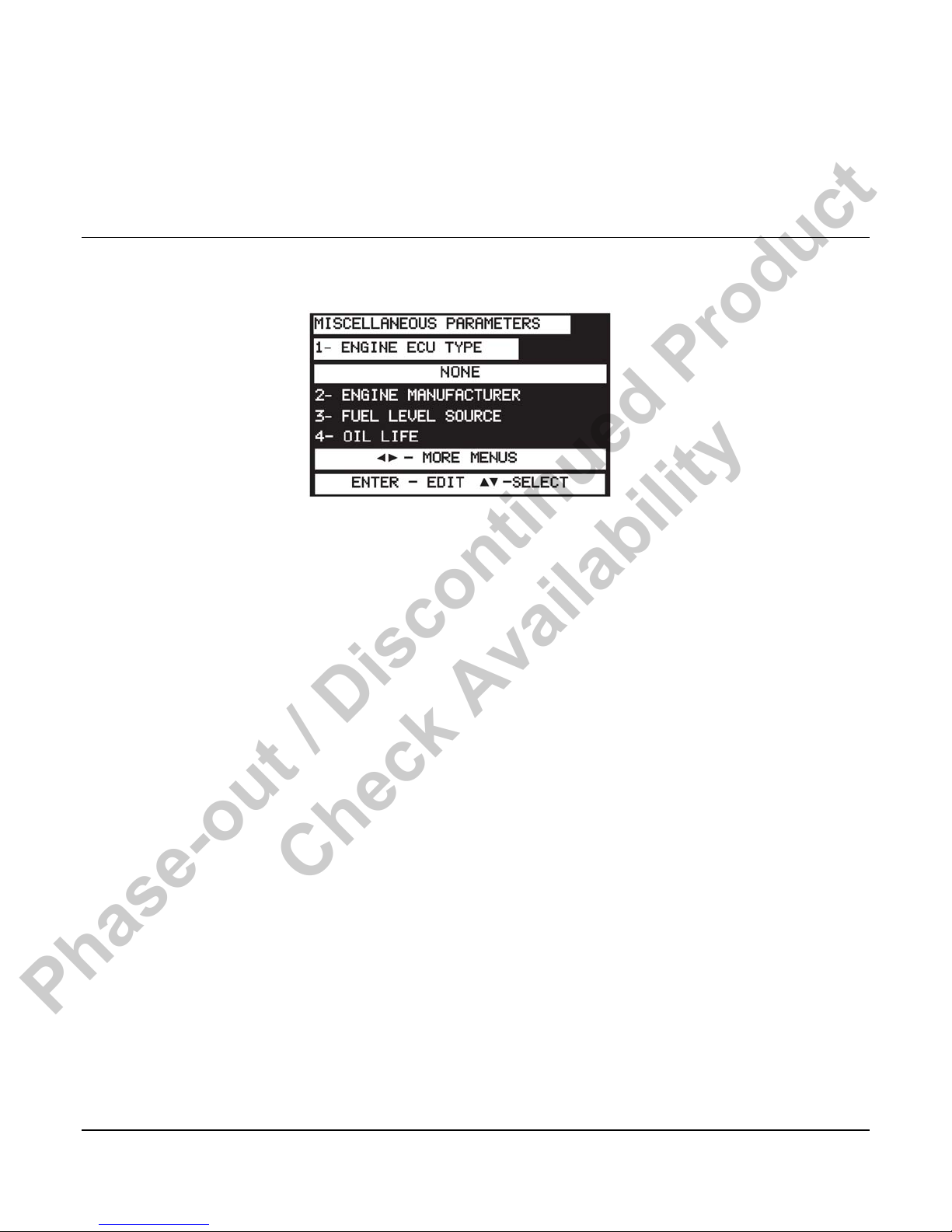
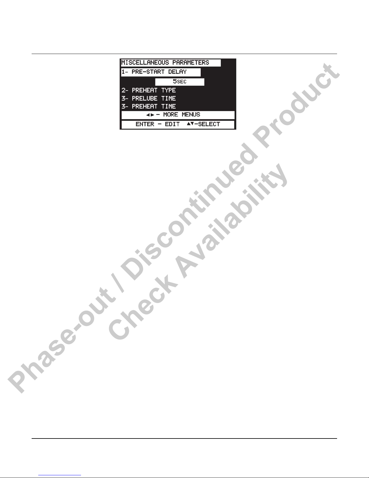
Miscellaneous Parameters
Review the materials supplied with the engine/ECU by the manufacturer to become familiar
with the specifics of your engine.
1. Engine ECU Type - Selects which ECU communications interface will be used to provide
engine parameters.
a. None (mechanically governed/controlled engine) (Default)
b. J1939
Section 75 00-02-0522
04-06-11 - 13 -
Phase-out / Discontinued Product
Check Availability
2. Crank Cut Type - Selects the primary crank and the secondary crank cuts. The options are
as follows:
Primary Secondary
J1939 MPU
J1939 AC Freq
J1939 Digit input
J1939 None
MPU J1939
MPU AC Freq
MPU Digit input
MPU None
AC Freq J1939
AC Freq MPU
AC Freq Digit input
AC Freq None
3. ECU Address Claim
a. None Required
b. Single ECU
c. Multiple ECU’s
4. Engine Manufacturer - Selects engine manufacturer.
Manufacturer Manufacturer
a
b
Section 75 00-02-0522
04-06-11 - 14 -
Caterpillar
Cummins
i
j
Isuzu
Kubota

Phase-out / Discontinued Product
Check Availability
c
d
e
f
g
h
NOTE: Caterpillar, Cummins, Deere, Detroit, Deutz, Ford, GM, Hatz, Isuzu,
Kubota, Lister-Petter, Mercedes, Perkins, Volvo are registered trademarks of
their respective corporations
5. J1939 Crankcut Count - Is the number of consecutive measurements of the RPM above
the Crankcut RPM, required to achieve crank disconnect.
6. Fuel Level Source - Select level source.
Deere
Detroit
Deutz
Ford
GM
Hatz
k
l
m
n
o
Lister-Petter
Mercedes
Perkins
Volvo
Other (Default)
a. None (Default)
b. J1939
c. Analog Input
7. Oil Life - Sets service interval timer for end user maintenance reminder. (Default 100
hours)
8. Oil Filter Life - Sets service interval timer for end user maintenance reminder. (Default 100
hours)
9. Belt Life - Sets service interval timer for end user maintenance reminder. (Default 100
hours)
10. Battery Life - Sets service interval timer for end user maintenance reminder. (Default 100
hours)
11. Fuel Filter Life - Sets service interval timer for end user maintenance reminder. (Default
100 hours)
12. Air Filter Life - Sets service interval timer for end user maintenance reminder. (Default
100 hours)
13. Overhaul Life - Sets service interval timer for end user maintenance reminder. (Default
1000 x 10 hours)
Section 75 00-02-0522
04-06-11 - 15 -
Phase-out / Discontinued Product
Check Availability
Engine Parameters
1. Pre-Autostart Delay - When system is in automatic mode, sets how long unit waits after a
remote run signal is active before proceeding with automatic start sequence. (Default 5
seconds, set to zero to bypass.)
2. Pre-Heat Type - Determines how long the preheat output is active.
a. None - No preheat. (Default)
b. Pre-Crank - For strictly the preheat timer length.
c. Crank Through - Preheat for the preheat timer + crank time.
d. Bypass Timer - Preheat + crank + start up lockout bypass.
e. Warm-Up - Preheat + crank + start up lockout bypass + warm-
up.
3. Pre-Lube Time - Amount of time a prelube output stays on prior to allowing a start. (Default
ø sec.)
4. Pre-Heat Timer - Amount of time that an engine is preheated prior to cranking. (Default ø
sec.)
5. Purge Crank Time - In gaseous-fueled engine applications, a purge crank is used to
prevent gas build up and vent any accumulated gaseous fuel from the system so that it will
start with a known condition. The engine cranks for a pre-settable time with the fuel output deenergized. (Default ø sec.)
6. Crank Time - In an automatic crank cycle the longest time that the engine cranking motor
can be energized. (Default is 15 sec.)
7. Crank Rest Time - In an automatic crank cycle, the time that the engine cranking motor is
off between crank attempts. (Default 15 sec.)
8. Start Attempts - The maximum number of times that the engine cranking motor is
energized without a successful engine start. (Default 3 cycles)
9. Startup Bypass Time - Temporarily disables the low engine oil pressure, high engine
temperature and various other shutdown faults until the engine can come to a running
condition. (Default 15 sec.)
Section 75 00-02-0522
04-06-11 - 16 -
 Loading...