

Page 1

HelmView
450
Model HV450
Operation Manual
00-02-0870
2015-04-16
Section 78
Page 2

In order to consistently bring you the highest quality, full-featured products, we reserve the right to change our
specifications and designs at any time. The latest version of this manual can be found at www.fwmurphy.com.
BEFORE BEGINNING INSTALLATION OF THI S MURPHY
PRODUCT:
• Read and follow all installation instructions.
• Please contact Enovation Controls immediately if you have
any questions.
• A visual inspection of this product for damage during
shipping is recommended before installation.
• It is your responsibility to ensure that qualified mechanical
and electrical technicians install this product.
Contact Enovation Controls Technical Service if you have any
questions or concerns at: +1 918-317-4100.
Page 3

Table of Contents
Product Information ................................................................................................................... 4
Forum Access ...................................................................................................................... 4
HV450 Features and Operations .............................................................................................. 5
Setting Up your HV450 Display for the First Time ................................................................. 6
Product Features ........................................................................................................................ 8
Power Up .............................................................................................................................. 8
Main Menu ............................................................................................................................ 8
Gauge Display ..................................................................................................................... 9
Engine Diagnostics ...........................................................................................................11
Fault Code Pop-Ups ..........................................................................................................12
User Settings .....................................................................................................................13
Utilities ................................................................................................................................18
Section 78 00-02-0870
2015-04-16 - 3 -
Page 4

Product Information
The HelmView™ HV450 display was specifically designed for instrumentation and control on
electronically controlled engines. These engines communicate using SAE J1939 and NMEA
2000 protocols. The HV450 display allows operators to view many different engine and
transmission parameters and service codes. The unit can simultaneously display port and
starboard (left and right, respectively) information. Optional upgrades (software and firmware)
are available to expand the usability. For more information, review the following summary
about the Enovation Controls Murphy Forum.
Forum Access
Enovation Controls has created a forum for PowerVision Configuration Studio ® supported
products. The forum is a location where a demonstration/trial version of the PowerVision
configuration tool is available for download. Many frequently asked questions are stored on the
forum along with demo configurations and examples on how to configure products. Please use
the link below and register for the forum:
http://forum.fwmurphy.com/
Once you register, you will receive your user name and password confirmation in separate
emails. Go to the Forum and log in; a page displays indicating a successful login. Almost
immediately, the page is directed to the Demo Users Forum. From here, you can investigate
and download a demo-con fig urat ion software tool or review previously asked questions.
In addition, the Forum contains software that has been released to the public. You can obt ai n
software updates here, so check the Forum regularly. Use the link below to go directly to the
software section:
http://forum.fwmurphy.com/viewtopic.php?f=10&t=43
This tool allows you to test and even build your own configurations. You can save them, but if
you would like to download the configuration to a product, please contact your local sales
representative.
Section 78 00-02-0870
2015-04-16 - 4 -
Page 5
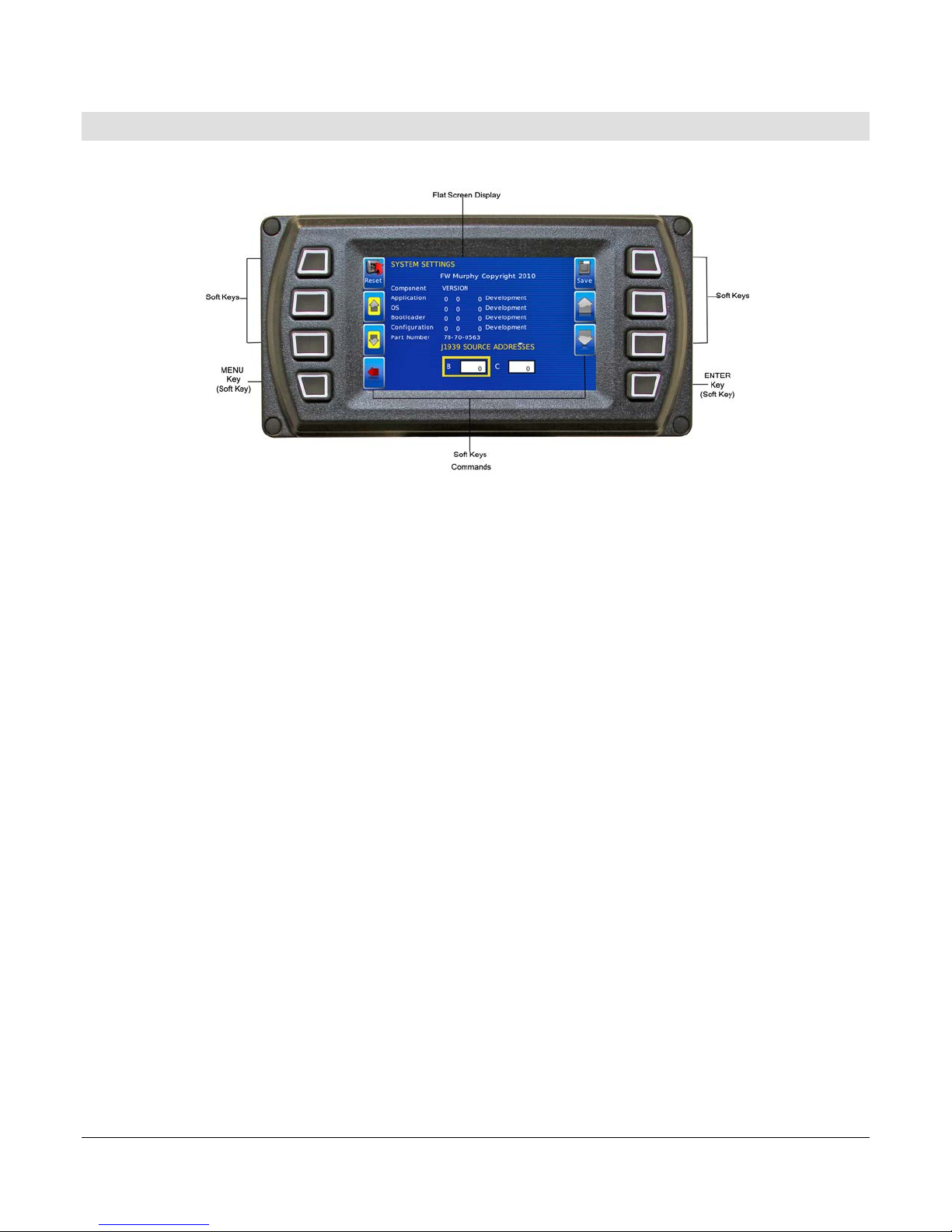
HV450 Features and Operations
LCD Screen Display
A color screen displays gauges, soft key commands and fault messages, as well as menu
options for setup and configuration.
Soft Key Commands
Columns of vertical commands may be located to the left and/or right of the display. They will
change according to the options available for the screen being displayed.
Soft Keys
The soft keys correspond to the soft key commands and allow selections to be made
accordingly.
MENU Key
The bottom left key is a soft key reserved in most cases for the Menu. In rare cases, it could be
used for other options. Pres si ng the MENU key at any time displays the list of menu options. If
not labeled, it is the MENU key.
ENTER Key
The bottom right key is a soft key reserved in most cases for Enter. In rare cases, it could be
used for other options. Pressing the ENTER key will select the option displayed much like the
ENTER key on a keyboard. If not labeled, it is the ENTER key
Section 78 00-02-0870
2015-04-16 - 5 -
Page 6
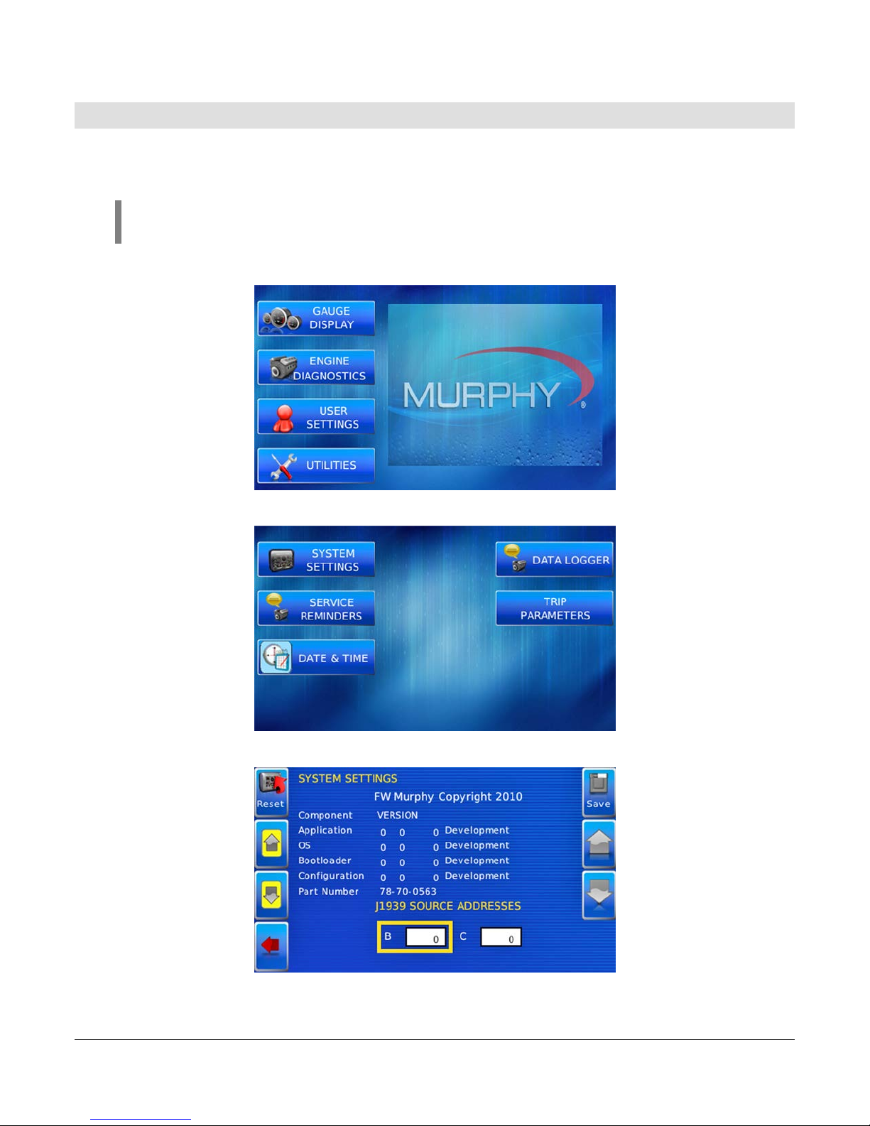
Setting Up your HV450 Display for the First Time
The guidelines presented below are intended for setting up the HV450 display for the first t ime.
Once the configuration is set up, there is no need to revisit or change any of the settings.
NOTE: If you require assistance during the set-up process, contact Enovation
Controls customer support at +1(918) 317-4100.
1. At the main menu, press the soft key to the left of Utilities.
2. The Utilities sub-menu is displayed.
3. From the Utilities sub-menu, select System Settings. The following screen is displayed.
Section 78 00-02-0870
2015-04-16 - 6 -
Page 7
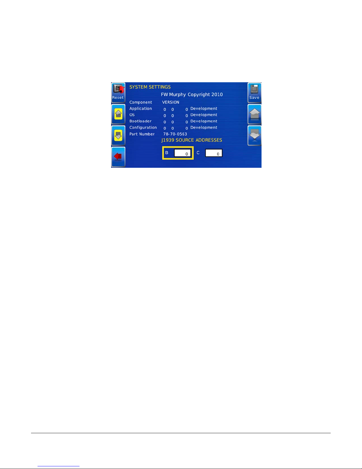
4. With the cursor highlighting the J1939 source addresses, use the left side soft keys to
scroll through the ports and the right side soft keys to change the address. Press the
Save key to save selected changes or the Restore Defaults key to return to the default
settings.
Section 78 00-02-0870
2015-04-16 - 7 -
Page 8
Product Features
Power Up
There are two options to connecting the HV450 display:
• The battery and ignition inputs to display are both connected to the batt er y
• The battery input is connected to the battery, and the ignition input is connected to the
ignition switch.
NOTE: If both are connected to the battery, then an inline battery
disconnect must be installed.
When the ignition is turned on, the HV450 display powers up, and the engine health statistics
can be viewed via preset gauges. To see more gauge screens, press the Enter key.
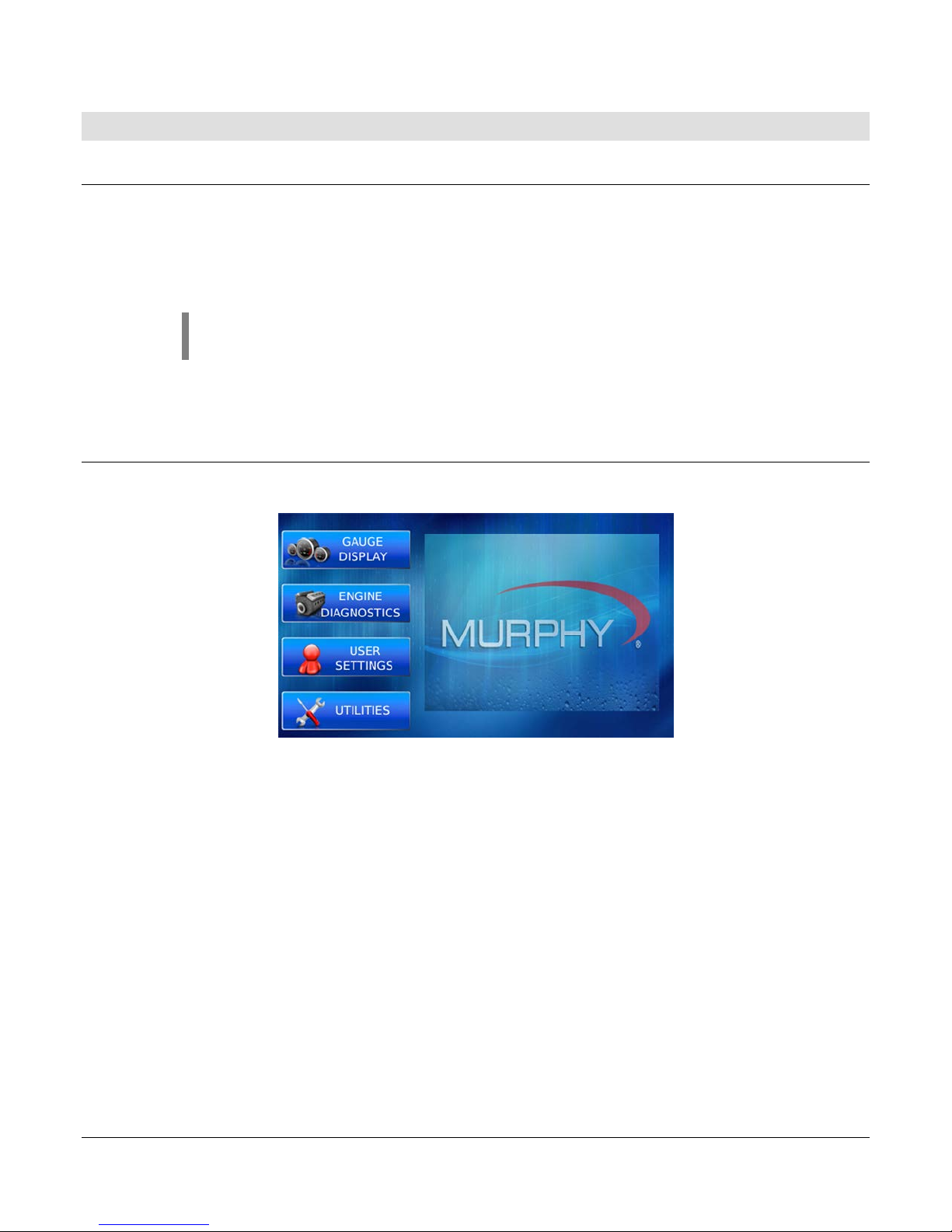
Main Menu
The main menu is activated at any time by pressing the Menu key on the display.
The following features are acces s ed t hr oug h t he mai n me nu:
• Gauge Display – provides a series of screens that display engine and auxiliary
information in a variety of formats.
• Engine Diagnostics – displays a list of engine fault codes and descriptions through a
DM1 message structure.
• User Settings – allows you to customize the display options for ambient light and
brightness, set US or metric units, language, specify the Home screen and screen setup
status.
• Utilities – allows configuration of the plug address. Also displays software version
information at the top of the page.
Section 78 00-02-0870
2015-04-16 - 8 -
Page 9

Gauge Display
The Gauge Display screen consists of several predefined layouts that contain combinations of
analog gauges, straight bar gauges or digital (text) readouts. These screens are displayed
upon startup.
To scroll through the various gauge screens, press the Prev and Next soft keys. This can be
repeated until all scree ns have been viewed. The currently displayed screen will stay active
until another key is pressed.
Soft Key Commands
When a Gauge Display screen is active, pressing the Enter key will display soft key
commands, as shown below. Continuing to press Enter will toggle through any additional soft
keys and will eventually remove the soft key commands from the screen.
Soft Key commands provide quick navigation and access to the following features:
• Home
• Video Input
• Prev
• Day/Night
• Video
• Next
Home - This one-touch navigation feature allows a predefined Home screen to be accessed
from the available Gauge Display screens. Once selected, the Home screen will be displayed
anytime the Home key is pressed.
NOTE: For instructions on how to set up the Home screen, refer to the User
Settings section of this manual.
Video Input – Allows you to toggle between two different video inputs that will be displayed on
various screens.
Section 78 00-02-0870
2015-04-16 - 9 -
Page 10

NOTE: .This feature can also be changed in the User Settings section of this
manual.
Day/Night - Allows you to toggle the display screen between Day View and Night View.
NOTE: This feature can also be changed in the User Settings section of this
manual.
Video – When enabled, displays either full-screen video or partial video within a window on the
gauge display.
NOTE: For instructions on how to enable full or partial screen video, refer to the
User Settings secti o n of this manual.
Full View Video
NOTE: For instructions on how to turn screens ON or OFF, refer to the User
Settings section of this manual.
Section 78 00-02-0870
2015-04-16 - 10 -
Page 11

Engine Diagnostics
After choosing Engine Diagnostics from the Menu, the display will query the engine(s) ECU
and provide feedback on any diagnostic codes that have been activated and stored in the ECU
for service needs.
The Engine Diagnostics option displays faults based on engine or auxiliary source.
The following is a list of field definitions contained on the Engine Diagnostics screen:
• Device ID – identi fies the comp on ent hav i ng the fault ; eng i ne 1, 2 or auxiliary.
• Address – identifies the address of the source of the fault (populates the Device ID).
• Status – indicates whether the fault has been c or rec ted.
• SPN –Suspect Parameter Number - fault code
If not translated into text by the HV450 display, see the engine manufacturer's literature
for the definition of the SPN number.
• FMI – Failure Mode Indicator - fault code
The FMI is defined by SAE J1939. If not translated into text, see the SAE standard or
the engine manufactur er ' s lit erat ur e.
• Occurrence Count (OC) – The number of times t he ev ent has bee n flag ged.
• Description – Most common SPNs and FMIs have text for the description stored in the
HV450 display. If there is no text, then this SPN and FMI must be defined by referring to
the engine manufacturer, or the SAE J1939 standard.
• Correction – Troubleshooting guidelines for corrective action to take in addressing the
fault.
NOTE: This field is only used with certain brands and models of engines.
Section 78 00-02-0870
2015-04-16 - 11 -
Page 12

Fault Code Pop-Ups
A fault condition will trigger a pop-up dialog box on the screen describing the nature of the
fault. Corresponding red or amber fault lights on the corners of the unit are also activated to
indicate the severity of the fault. The following screens are examples of warning and shutdown fault code pop-ups.
Warning Shut-down
How to Hide/Show Faults
To hide the fault code pop-up being displayed on the screen, press the sof t key on the right
next to the Hide i con. The pop-up will disappear; however the Warning or Stop icon will
remain on the screen to indicate there is still a fault. Pressing Hide does not clear the fault; it
only hides the pop-up message.
When a fault code has been hidden, a Recall icon will remain on the right side. When this soft
key is pressed, the fault code will again be displayed. When a pop-up message has been
activated, a pop-up message will be displayed until the alarm is acknowledged by pressing the
Hide key.
Warning Recall View
Scrolling Through Multiple Messages
The title bar of the fault code pop-up may indicate multiple messages, as in Diagnostic
Message 1 of 3. Press the Prev and Next keys to scroll through the different messages.
Section 78 00-02-0870
2015-04-16 - 12 -
Page 13

User Settings
User Settings provides options to specify viewing preferences for the HV450 Display. Pressing
yellow Up and Down arrows navigates through the options. To change an option, press the
corresponding soft key button next to the desired soft key command.
Ambient Light
Night and Day options are provided for ambient lighting. The screens below illustrate these
options. When the ambient lighting settings are changed in User Settings, the power-on
default is changed.
NOTE: The ambient lighting option is also accessible through soft key
commands on the gauge display screens. When selected, the Day/Night soft key
toggles the display to the opposite mode. Pressing the Night button will toggle
between the Red and Blue versions of the Night mode.
Section 78 00-02-0870
2015-04-16 - 13 -
Page 14

Brightness
You can set the brightness control by using the soft keys to change the settings in +5%
increments until the desired brightness is achieved.
NOTE: Brightness levels will change with ambient light setting. Two
brightness levels are saved - one for day and one for night.
Units
Select how units are displayed by using the soft keys to select from the following:
• USA Standard
• Metric Bar
• Metric kPa
• British Standard
Section 78 00-02-0870
2015-04-16 - 14 -
Page 15

Language
This option allows you to select the language that will be displayed on the HV450. This unit
supports English. Available languages include: Russian, Czech, Japanese, Brazilian
Portuguese, French, Spanish, German, Italian and Chinese.
Video Mode
This option provides the choice between NTSC and PAL. The unit will reboot upon this setting
change.
Section 78 00-02-0870
2015-04-16 - 15 -
Page 16

Video Input
This option toggles between two video inputs.
Screen Setup
The Screen Setup option provides a list of screens that can be shown when accessing the
Gauge Display screens.
Press the Up and Down arrow keys on the right to scroll through the screens.
Press the Home soft key to select the screen as home.
NOTE: An X in the On/Off check box indicates the screen is on. A blank
check box indicates the screen is turned off.
Section 78 00-02-0870
2015-04-16 - 16 -
Page 17

The Screen Setup option also provides the user the ability to turn the screens ON or OFF by
pressing the Enable/Disable soft key. If a screen is turned OFF, it will not show up when
Gauge Display is activated.
Home Screen
The Home Screen will be the first screen shown when Gauge Display is selected from the
User Setting menu. The Home Screen is set to Engine by default and can be changed using
the Screen Setup options on the User Settings screen.
Video (Optional)
By default, the Video screen is on or Enabled. To Disable video, change Video option to Off in
the screen setup dialog box using the Enable/Disable key in the top right corner. An updated
image showing video screen highlighted / off will be displayed.
Save
Once all changes have been mad e, pr ess Save. The following confirmation screen is
displayed.
Section 78 00-02-0870
2015-04-16 - 17 -
Page 18

Restore Defaults
Restore Defaults sets the display to the original f actory settings. During troubleshooting, this
can be used as a last resort to completely reset the display to a known state.
To restore the default user settings, press Restore Defaults. The fol lowing confirmation
screen is displayed.
Backlight Toggle
This sets the Backlight to 0, and pressing any button will turn the backlight back on.
Utilities
Utilities screen allows you to reset external gauges and configure communication settings. It is
typically only accessed when the unit is first installed in order to configure the unit. The
following sub-menu is di spl ayed when Utilities is selected.
Section 78 00-02-0870
2015-04-16 - 18 -
Page 19

System Settings
The System Settings screen displays the current software version loaded on the HV450
display. You can set individual settings for the available options and Save or choose to select
Restore Defaults for the factory settings.
The yellow Up and Down keys on the left allow you to move the cursor through J1939 Source
Addresses fields. W hile the cursor is highlighting a field, the gray Up and Down keys scroll
through available options. Once all the options have been selected, press Save.
Service Reminders
This option allows you to reset the five built-in service reminders:
• Change Engine Oil – Default interval 50.0 Hrs.
• Chang Air Filters – Default interval 75.0 Hrs.
• Change Hydraulic Oil – Default interval 100.0 Hrs.
• Service Engine – Default interval 125.0 Hrs.
• Service Machine – Default interval 150.0 Hrs.
NOTE: The HV450 is Tier 4 com pliant. If there are any questions on the
Murphy Standard Configuration, please contact Murphy technical services
at: (918) 317-1113.
Section 78 00-02-0870
2015-04-16 - 19 -
Page 20

Date and Time
This option allows you to adjust the year, month, day, hour, minute, second, time zone and daylight
saving time.
Year Month
Day Hour
Minute Second
Section 78 00-02-0870
2015-04-16 - 20 -
Page 21

Icon
Description
Starts the recording.
Stops the recording.
Clears the log.
Saves the log.
Time Zone Offset Daylight Saving Time
Data Logger
This option allows you to record data that can be captured on a flash drive.
Section 78 00-02-0870
2015-04-16 - 21 -
Page 22

T rip Parameters
This option allows you to choose whether to use J1939 trip fuel source or Calculators trip fuel source.
Reset – resets the calculated trip fuel parameter.
Section 78 00-02-0870
2015-04-16 - 22 -
Page 23

THIS PAGE INTENTIONALLY LEFT BLANK
Section 78 00-02-0870
2015-04-16 - 23 -
Page 24

 Loading...