

Page 1
EMS PRO
Engine Monitoring System Controller
Installation and Operations Manual
00-02-0716
2013-06-03
Section 40
Page 2

systems.
In order to consistently bring you the highest quality, full featured products, we reserve the right to change our
specifications and designs at any time.
ENOVATION CONTROLS has made efforts to ensure the reliability of the EMS PRO
and to recommend safe use practices in system applications. Please note that in any
application, operation and controller failures can occur. These failures might result in
full control outputs or other outputs that might cause damage to or unsafe conditions
in the equipment or process connected to the EMS PRO.
Good engineering practices, electrical codes, and insurance regulations require that
you use independent external protective devices to prevent potentially dangerous or
unsafe conditions. Assume that the EMS PRO can fail with outputs full ON, outputs
full OFF or that other unexpected conditions can occur.
Please read the following information before installing.
BEFORE BEGINNING INSTALLATION OF THIS MURPHY
PRODUCT:
• This installation information is intended for all EMS PRO Series models. A visual
inspection of this product before installation for any damage during shipping is
recommended.
• Disconnect all electrical power to the machine. Failure to disconnect all electrical
power connections before welding can result in damage to the panel and/or its
components.
• It is your responsibility to have a qualified technician install the unit and make sure
installation confirms with local codes.
• Observe all Warnings and Cautions in each section of these instructions.
• The EMS PRO is designed for use in industrial environments. There might be
potential difficulties in ensuring electromagnetic compatibility in other
environments due to conducted as well as radiated disturbances.
• Please contact ENOVATION CONTROLS immediately if you have any questions.
IMPORTANT! False or improper use and operation of electronic
products could be dangerous. It is required that point-of-operation
guarding devices be installed and maintained. All such devices must
meet OSHA and ANSI Machine safety standards. The manufacturer shall
not accept any responsibility for installation, application or safety of
Page 3

Table of Contents
Introduction ................................................................................................................................. 1
Product Description ......................................................................................................1
User Interface and Navigation ......................................................................................2
Quick Set Up ............................................................................................................................... 6
Setting the Time/Date Clock .........................................................................................7
Setting for Mechanical Engines ....................................................................................7
Start/Stop Settings .......................................................................................................8
System Throttling Types ..............................................................................................9
Transducer Types ...................................................................................................... 10
Tier 4 Emissions ......................................................................................................... 11
Unit System – Metric or English ................................................................................. 12
Operational Directions ............................................................................................................ 12
AUTO Start/Stop Sequence ....................................................................................... 12
Start Sequence .......................................................................................................... 13
Stop Sequence ........................................................................................................... 15
Manual Start/Stop Sequence ..................................................................................... 16
Special Features ........................................................................................................ 18
Menus ........................................................................................................................ 19
Inputs and Outputs ..................................................................................................... 31
General Information ................................................................................................................. 33
LCD CONTRAST ADJUSTMENT ON STARTUP ...................................................... 33
General Wiring Precautions ....................................................................................... 33
Communications ........................................................................................................ 34
ENTRY CODE SUPPLEMENT ................................................................................................. 38
LOADING PROGRAM ............................................................................................... 38
Installation ................................................................................................................................. 39
EMS PRO Mounting and Dimensions ........................................................................ 39
Specifications ........................................................................................................................... 40
Page 4

NOTES
Page 5

Introduction
This document is designed to support a user in getting familiar with the EMS PRO and how to navigate
the interface, modify the settings and install and operate the controller. The Quick Set Up guide assists
with establishing the different functions in the EMS PRO System Controller. Before attempting to set
up the controller, be sure to read and understand this manual in its entirety.
Product Description
The EMS PRO is a flexible, all-in-one customizable unit that meets the needs of engine-driven pumping
equipment applications. The EMS PRO is a dedicated microprocessor-based, single-engine controller.
It offers field-adjustable operating parameters that can be changed without the need for a laptop
computer. It is able to support both mechanical and J1939 electronic engines.
The EMS PRO has a selectable auto start/stop with many auto throttling options. The auto start/stop
options (Single Contact, Floats, Momentary, and Transducer) are available at the touch of a button. In
addition, there are many performance-enhancing features, all of which are available via a back-lit
operator interface that’s easy to learn and use. The display is readable day or night.
The EMS PRO is designed for use with a SCADA system, offering Modbus® RTU protocol on either the
RS232 or RS485 port. See the Modbus portion of this manual for details.
NOTE: Harness kit 40000536 is available to “bring out” the (2) wire RS485 to the
bottom of the enclosure. The RS232 is accessed via a DB9 connector located on
the display/CPU board. Customer modification to the enclosure is required to use
either port.
Section 40 00-02-0716
2013-06-03 - 1 -
Page 6
User Interface and Navigation
This section defines how to navigate through the EMS PRO user interface. It will assist the user in
understanding the screens and keys used to modify settings and how each works.
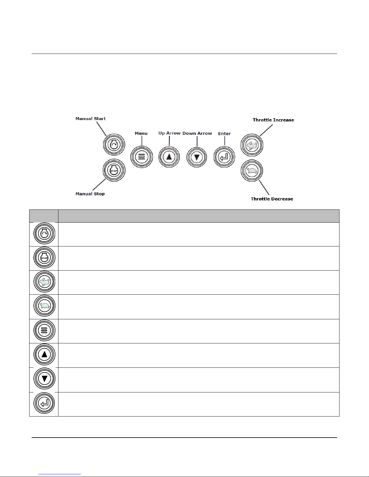
Membrane Keypad
The membrane keypad is made up of eight buttons. All of the functions for the EMS PRO can be set
using these eight buttons.
ICON Description
“START” = In the “MAN” (manual) mode this will initiate a start sequence. Can be used for
local auto start if “Local Pushbutton” is selected in start/stop type, S35.
“STOP” = In the “MAN” (manual) mode this will initiate a stop sequence. Can be used for
local auto stop if “Local Pushbutton” is selected in start/stop type, S35.
“THROTTLE INCREASE” = In the “MAN” (manual) mode this will increase engine speed.
“THROTTLE DECREASE” = In the “MAN” (manual) mode this will decrease engine speed.
“MENU” = Toggles between the front display and the password window and allows user to
exit menus.
“UP” arrow = Scrolling on the front display, scrolling through and increasing values in the “S”
& “P” numbers.
“DOWN” arrow = Scrolling on the front display, scrolling through and decreasing values in the
“S” & “P” numbers.
“ENTER” = Getting into the “S” or “P” numbers group after the correct entry code is entered,
getting into an actual “S” or “P” number selected to make changes.
Section 40 00-02-0716
2013-06-03 - 2 -
Page 7
Input
Description
AUTO
Functions described in the “Auto Start/Stop Sequence” of this document.
OFF
Disconnects control power to prevent the engine from starting or continuing to run through the
control panel. The OFF position provides an immediate shutdown whenever the key switch is
placed in this position while the engine is running in either the automatic or manual modes.
MAN
Functions as described in the “MAN Start/Stop Sequence” in this document.
Screens Displayed
Screen Name
Description
FW MURPHY or
This is the last line of the text page when pressing the down arrow key from
BUILD xxxxxx
Refer to the program and build number when requesting technical assistance.
PROGRAM 50333178
Refer to the program and build number when requesting technical assistance.
Key Switch
The controller accepts inputs from a 3 position key switch. The 3 positions are “AUTO”, “OFF” and
“MAN”:
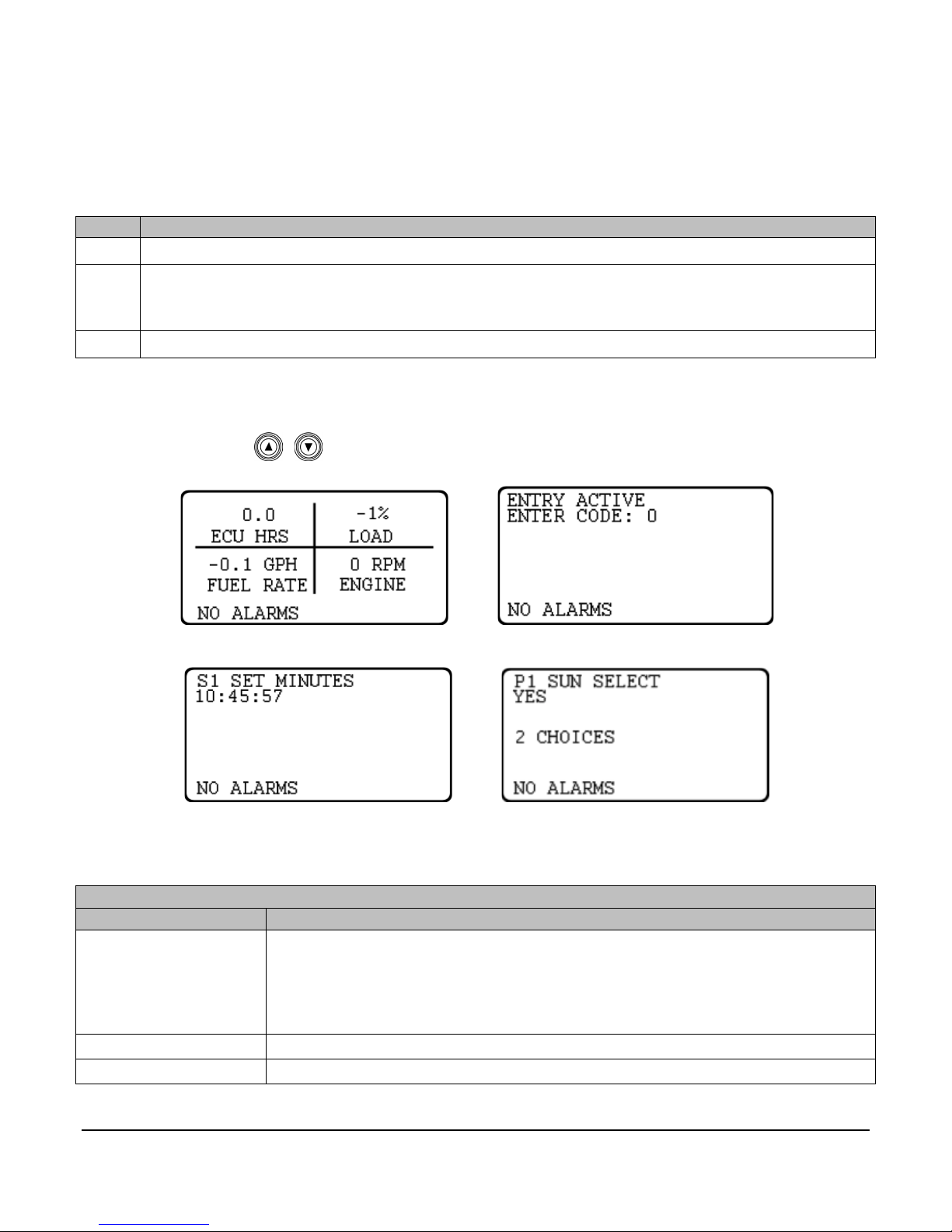
Screens Displayed
During normal operation, the controller allows you to scroll through a number of informative front screen
displays by using the membrane keys. Below are several example screens.
Example Four-Up Screen Entry Code Screen
Example S-Number Screen Example P-Number Screen
The screens displayed by the EMS PRO are listed and described below:
MURPHY or
ENOVATION
CONTROLS
the default screen.
Section 40 00-02-0716
2013-06-03 - 3 -
Page 8
Screens Displayed
Screen Name
Description
SELECTOR XXXX
There are three positions displayed on this line: AUTO and MAN. When a start
START”, “CLOCK START”, “SCADA START”
DAY OF THE WEEK
This line shows the present day of the week.
DD MMM YYYY
This line displays the present date.
HH:MM:SS
This line shows the present time.
STATE:
XXXXXXXXXX
The following are the different states the controller will execute during the auto
sequence:
signal is active, the display will change to show the start option being used in
place of Auto or MAN: “SINGLE CONTACT START”, “FLOAT START”,
“MOMENTARY START”, “PRESSURE START”, “LEVEL START”, “TEMP
Section 40 00-02-0716
2013-06-03 - 4 -
Page 9

Screens Displayed
Screen Name
Description
STATE:
This text line displays any of the following states the controller will execute
OFF position and then back to AUTO or MAN.
FUEL XXX%
This displays the current fuel level as sensed from a sender.
SYS BAT XX.X VDC
This displays the current engine battery voltage.
SYS HRS or ECU HRS
This displays the current total engine run time. The prompt and data shown in
SELECT”. S39 will not appear when S38 is set to “MECHANICAL”.
LEAD SPD XXXX RPM
This displays the internally generated lead/command speed.
during the auto sequence:
• PANEL READY occurs when the key switch is in the AUTO position and
no shutdowns have occurred. The controller is waiting for an auto start
condition to occur.
• START DELAY occurs when a start signal is active and the start delay is
timing. The start signal must remain active throughout this delay before
the auto start sequence can continue.
• PRESTART occurs after the start delay expires. During this state, the
prestart output is turned ON. This output remains on until the engine
actually starts.
• WAIT FOR ECU occurs after the Prestart delay expires, if “ECU” is
selected in the engine type. During this state, the unit allows the ECU to
initialize prior to cranking. A “J1939 COMM FAIL” will occur if the PRO is
not receiving CAN data when this delay expires.
• CRANK ON occurs when cycle cranking begins. During this state, the
crank output is turned ON.
• CRANK OFF occurs when cycle cranking begins. During this state, the
crank output is turned OFF.
• RECRANK DELAY occurs if the engine speed drops below the “crank
stop” set point before the “shutdown lockout delay” expires. Cycle
cranking continues when this delay expires.
• WARMUP occurs after the engine starts. During this state, the engine is
throttled to the warm-up RPM until this delay expires.
• AT LOAD occurs after the Warm-up delay expires. The low discharge
pressure shutdown is armed when this delay expires.
• FILL MODE occurs after the Warm-up delay expires. During this state,
the engine is throttled to minimum rpm and held there until this delay
expires.
• STOP DELAY occurs when a stop signal is active and the stop delay is
timing. The stop signal must remain active throughout this delay before
the auto stop sequence can continue.
• COOLDOWN occurs after the Stop Delay has expired. During this state,
the engine is throttled to the cooldown rpm.
• SHUTDOWN occurs if a shutdown condition is detected. Reasons for
shutdown include low oil pressure, high engine temperature, overspeed,
etc. During this state, the engine is signaled to shutdown and all start
signals are ignored until the state is reset by moving the key switch to the
XXXX.X
this display is dependent on S38 ”ENGINE TYPE” and S39 ”ECU HOUR
Section 40 00-02-0716
2013-06-03 - 5 -
Page 10

Screens Displayed
Screen Name
Description
ENG XXXX RPM
This displays the current engine RPM sensed from either a magnetic pickup
or as broadcasted from the ECU.
OIL PR XXX PSI
This displays the current engine oil pressure as sensed from an electric
gauge sender, or as broadcasted from the ECU.
ENG TEMP XXX °F
This displays the current engine jacket water temperature as sensed from an
electric gauge sender, or as broadcasted from the ECU.
DISCH PR XXX PSI
(IF SELECTED)
This displays the current discharge pressure as sensed from a transducer.
LEVEL XX.X
(IF SELECTED)
This displays the current system level as sensed from a transducer.
AMB TEMP XXX °F
(IF SELECTED)
This displays the current ambient temperature as sensed from a Murphy
Model 12 transducer.
LOCAL THROT
This is only show if Local Throttle is selected in S36.
SOOT LEVEL
This shows the soot level percentage. There are also 3 alarms associated
“REGEN NEEDED HIGH”.
UREA LEVEL
This shows the urea level percentage as broadcasted over CAN SPN 1761.
FIRST FOUR-UP
(DEFAULT SCREEN)
The first four-up screen should display Engine Oil Pressure, Engine Coolant
powering up the controller.
SECOND FOUR-UP
The second four-up screen should display Run Hours, Fuel Consumption,
icons by temporarily writing over ECU run hours, LOAD%, and FUEL RATE.
SHUTDOWN SCREEN
This screen shows the last five shutdowns that have occurred. This screen can
(IF SELECTED)
(IF SELECTED)
(IF SELECTED)
SCREEN
ECU ONLY SCREEN
Quick Set Up
with this Status sent from the ECU. The Alarms will be displayed on the
Alarm line as “REGEN NEEDED LOW”, “REGEN NEEDED MEDIUM”, or
Temp, Battery Voltage, & Engine RPM. This is the default screen when
Engine Load %, & Engine RPM. This screen can be viewed by pressing the
arrow up key from the default screen. This screen will also display (3) Tier 4
be accessed by pressing the arrow up key past the four-up screen(s).
This section is to help in setting portions of the program in which cover the primary uses of this
controller. The steps below will only cover how to change certain portions of the program to better suit
your application. There are other parameters to be setup in the menus before the unit is placed in
service.
NOTE: This section is used as a reference guide and this entire document
should be completely read and understood before ever placing the controller into
service.
Section 40 00-02-0716
2013-06-03 - 6 -
Page 11

Setting the Time/Date Clock
Setting up the clock is critical to many of the other functions of the EMS PRO. Use the following steps
to set the EMS PRO Clock. The clock includes the time (displayed in 24hr format), the date and the day
of the week.
1. Access the S numbers menu by pressing [Menu].
2. Use the [Up Arrow] and [Down Arrow] to scroll to the correct Entry Code (See Entry Code
Supplement for Entry Codes).
3. When the correct Entry Code is displayed, press [Enter] to access the S numbers menu.
NOTE: If the incorrect code is entered, “PASSWORD FAILURE” will appear on
the display. Press [Enter] and try again.
NOTE: (S1 - S6) are the S-Numbers used to set the clock. See the S number
section of this manual for details.
4. Press [Up Arrow] and [Down Arrow] to scroll through the S-Numbers.
5. Press [Enter] when displaying the correct S number to highlight the current setting.
6. Use the [Up Arrow] and [Down Arrow] to enter the correct setting in the S number.
7. Press [Enter] to un-highlight the value and to move to another S number.
8. Repeat steps 4 through 7 for each clock and date setting.
9. When setup is complete, exit the S Menu by pressing [Menu].
NOTE: The user must be out of the S or P number (un-highlighted) to exit the
menu.
NOTE: Accessing the S or P numbers to change any set point is done in the
same manner as above.
10. Verify the clock is set to the current time, date and day of the week.
Setting for Mechanical Engines
The EMS PRO Controller factory defaults are set to run on an ECU equipped engine. In order to set
the controller to work on a mechanical engine, follow the steps below:
1. Access the S numbers menu by pressing [Menu].
2. Use the [Up Arrow] and [Down Arrow] to scroll to the correct Entry Code (See Entry Code
Supplement for Entry Codes).
3. When the correct Entry Code is displayed, press [Enter] to access the S numbers menu.
NOTE: If the incorrect code is entered, “PASSWORD FAILURE” will appear on
the display. Press [Enter] and try again.
Section 40 00-02-0716
2013-06-03 - 7 -
Page 12

NOTE: (S7, 38 & 40) are the S-Numbers used to set the controller for a
mechanical engine. See the S number section of this manual for details.
4. Press the [Up Arrow] and [Down Arrow] until (S38) ENGINE TYPE is displayed, press [Enter]
to highlight the current setting.
5. Press the [Up Arrow] and [Down Arrow] until MECHANICAL is displayed, press [Enter] to un-
highlight the new setting.
6. Press the [Up Arrow] and [Down Arrow] until (S40) ENG THR TYPE is displayed, press
[Enter] to highlight the current setting.
7. Press the [Up Arrow] and [Down Arrow] until MECHANICAL is highlighted then press [Enter]
to un-highlight the new setting.
8. Press the [Up Arrow] and [Down Arrow] until (S7) SPEED CALIB is displayed, press [Enter]
to highlight the current setting.
9. Press the [Up Arrow] and [Down Arrow] to enter the number of teeth on the engine’s flywheel
ring gear and press [Enter] to un-highlight the new setting.
10. Exit the S Menu by pressing [Menu].
NOTE: For mechanical engine throttling, see the PCBA SHUNTS section of this
manual for details.
Start/Stop Settings
There are five start/stop types in S35: SINGLE CONTACT, FLOATS, MOMENTARY, TRANSDUCER,
LOCAL PB (GREEN AND RED PUSHBUTTONS).
Single Contact Start/Stop:
The Single Contact Start/Stop is when a remote contact closes and remains closed for auto start, and
re-opens for auto stop.
(2) Float Start/Stop:
The (2) Float Start/Stop is when both float contacts are closed for auto start, and both float contacts are
open for auto stop.
Momentary Start/Stop:
The Momentary Start/Stop is when a contact closes momentarily for auto start, and a second contact
closes momentarily for auto stop.
Transducer Start/Stop:
A transducer is used for auto throttling. There are set points, allowing the operator to enter the
appropriate values.
Local Pushbutton Start/Stop:
The Local Pushbutton Start/Stop is when the local panel mounted green and red pushbuttons are used
for auto start/stop.
Section 40 00-02-0716
2013-06-03 - 8 -
Page 13

Use the following steps to select the correct start/stop:
1. Access the S numbers menu by pressing [Menu].
2. Use the [Up Arrow] and [Down Arrow] to scroll to the correct Entry Code (See Entry Code
Supplement for Entry Codes).
3. When the correct Entry Code is displayed, press [Enter] to access the S numbers menu.
NOTE: If the incorrect code is entered, “PASSWORD FAILURE” will appear on
the display. Press [Enter] and try again.
NOTE: S35 is the S-Number used for the start/stop type. See the S number
section of this manual for details.
4. Press the [Up Arrow] and [Down Arrow] until (S35) START/STOP SELECT is displayed,
press [Enter] to highlight the current setting.
5. Press the [Up Arrow] and [Down Arrow] until the desired selection is displayed, press
[Enter] to un-highlight the new setting.
6. Exit the S Menu by pressing [Menu].
System Throttling Types
There are (3) throttling types in S37: MAX. RPM, TRANSDUCER, LOCAL THROTTLE.
Max. RPM:
The Engine is throttled to the max. rpm set point.
Transducer:
A transducer is used for auto throttling. There are set points, allowing the operator to enter the
appropriate values.
Local Throttle:
An external 0-5 vdc potentiometer is used for auto throttling. There are set points, allowing the operator
to enter the appropriate values.
Use the following steps to select the correct transducer type:
1. Access the S numbers menu by pressing [Menu].
2. Use the [Up Arrow] and [Down Arrow] to scroll to the correct Entry Code (See Entry Code
Supplement for Entry Codes).
3. When the correct Entry Code is displayed, press [Enter] to access the S numbers menu.
NOTE: If the incorrect code is entered, “PASSWORD FAILURE” will appear on
the display. Press [Enter] and try again.
Section 40 00-02-0716
2013-06-03 - 9 -
Page 14

NOTE: S36 is the S-Number used for the transducer type. See the S number
section of this manual for details.
4. Press the [Up Arrow] and [Down Arrow] until (S36) SYSTEM THROTTLE TYPE is
displayed, press [Enter] to highlight the current setting.
5. Press the [Up Arrow] and [Down Arrow] until the desired selection is displayed, press
[Enter] to un-highlight the new setting.
6. Exit the S Menu by pressing [Menu].
Transducer Types
There are (10) transducer types in S37: NONE -- PRESSURE CONTROL -- LEVEL CONTROL -TEMPERATURE CONTROL -- PRESSURE CONTROL / LEVEL DISPLAY -- LEVEL CONTROL /
PRESSURE DISPLAY -- PRESSURE DISPLAY -- LEVEL DISPLAY --PRESSURE CONTROL / FLOW
STOP -- PRESSURE CONTROL / FLOW STOP & THROTTLE. Below are the step-by-step instructions
to set up these options.
None:
There is no transducer wired to the controller.
Pressure Control:
Pressure start/stop and throttling.
Level Control:
Level start/stop and throttling.
Temperature Control:
Temperature start/stop. Throttling to the maximum rpm set point will occur.
Pressure Control / Level Display:
Pressure start/stop, throttling, and level displayed with high and low alarms.
Level Control / Pressure Display:
Level start/stop, throttling, and pressure displayed with high and low shutdowns.
Pressure Display:
Pressure is displayed with high and low shutdowns.
Level Display:
Level is displayed with high and low alarm.
Pressure Control / Flow Stop:
Pressure start, throttling, and flow stop.
Pressure Control / Flow Stop & Throttle:
Pressure start, flow stop, and flow throttling.
Section 40 00-02-0716
2013-06-03 - 10 -
Page 15

Use the following steps to select the correct transducer type:
1. Access the S numbers menu by pressing [Menu].
2. Use the [Up Arrow] and [Down Arrow] to scroll to the correct Entry Code (See Entry
Code Supplement for Entry Codes).
3. When the correct Entry Code is displayed, press [Enter] to access the S numbers menu.
NOTE: If the incorrect code is entered, “PASSWORD FAILURE” will appear on
the display. Press [Enter] and try again.
NOTE: S37 is the S-Number used for the transducer type. See the S number
section of this manual for details.
4. Press the [Up Arrow] and [Down Arrow] until (S37) XDUCER TYPE is displayed, press
[Enter] to highlight the current setting.
5. Press the [Up Arrow] and [Down Arrow] until the desired selection is displayed, press
[Enter] to un-highlight the new setting.
6. Exit the S Menu by pressing [Menu].
Tier 4 Emissions
The Tier 4 Emissions set up allows users of the EMS PRO to use it on an Interim Tier 4 engine. The
controller displays the SOOT level when the engine has been de-rated and/or when regeneration
(regen) is required to return to normal service on the front display.
NOTE: Please read and understand S84 (Request DPF Regen) found in the Snumber table.
• If the regen is selected, the ECU will perform a regen automatically.
• If a regen is requested, the controller will command the ECU to perform a
regen. This feature will only occur if ECU conditions allow.
• If Inhibit Regen is selected, no regen occurs.
To use the controller on a Tier 4 engine, follow the steps below:
1. Access the S Menu by pressing [Menu]
2. Press the [Up Arrow] and [Down Arrow] to scroll to the correct Entry Code (See Entry Code
Supplement for Entry Codes).
3. Press the [Up Arrow] and [Down Arrow] until (S82) TIER RATING is displayed in the menu
and press [Enter].
4. Press the [Up Arrow] and [Down Arrow] until TIER 4 is highlighted and press [Enter].
5. Press the [Up Arrow] and [Down Arrow] until (S83) TIER4 STATE and press [Enter].button.
The default value is set to AUTO. If you want the engine state to be in INHIBIT DPF REGEN
use the [Up Arrow] and [Down Arrow] to highlight the text and press [Enter].
6. To set the Diesel Particulate Filter (DPF) Regeneration follow the steps below:
NOTE: If all conditions for a regen to occur are not met, this request could be
ignored by the ECU.
a. Access the S Menu by pressing [Menu]
b. Press the [Up Arrow] and [Down Arrow] to scroll to the correct Entry Code (See Entry
Code Supplement for Entry Codes).
Section 40 00-02-0716
2013-06-03 - 11 -
Page 16

c. Press the [Up Arrow] and [Down Arrow] until (S84) AUTO DPF REGEN is displayed in
the menu and press [Enter].
d. Press the [Up Arrow] until YES is highlighted and press [Enter].
NOTE: S84 is only available if S83”TIER 4 RATING” is set to 4, S38
“ENGINE TYPE” is set to ECU, the engine RPM is above S23 “CRANK
STOP RPM”, and the ECU output (Output 1) is on.
NOTE: Once the regen has started, this menu must continue to be
displayed until the regen is complete and NO is displayed on the menu.
e. Press [Menu] to exit the S Menu.
7. The following TIER 4 alarms will appear on the alarm line. Icons are displayed on the ECU 4 up
temporarily replacing ECU running hours, Load% and Fuel rate:
a. REGEN NEEDED LOW. (Status message based on Particulate Filter spn 3701)
b. REGEN NEEDED MEDIUM. (Status message based on Particulate Filter spn 3701)
c. REGEN NEEDED HIGH. (Status message based on Particulate Filter spn 3701)
d. REGEN NEEDED (Status message based on Particulate Filter spn 3697 with steady
and flashing ICON).
e. EXHAUST HIGH TEMP. (Based on spn 3698 with steady ICON).
f. REGEN INHIBIT (Status message based on spn 3703 with Steady ICON).
Unit System – Metric or English
This setting allows the user to change the default units from English units (PSI and °F) to Metric units
(KPA & °C). Use the following steps to change the units:
1. Access the S Menu by pressing [Menu]
2. Press the [Up Arrow] and [Down Arrow] to scroll to the correct Entry Code (See Entry Code
Supplement for Entry Codes).
3. Press the [Up Arrow] and [Down Arrow] until (S81) UNIT SYSTEM is displayed in the menu
and press [Enter].
4. Press the [Up Arrow] and [Down Arrow] until METRIC is highlighted and press [Enter].
5. Press [Menu] to exit the S Menu.
Operational Directions
AUTO Start/Stop Sequence
The following choices are available in the “start/stop type” S Number:
• Single Contact: A remote contact closes to start and re-opens to stop.
• Floats (2 contacts): Both contacts close for start and both contacts re-open for stop.
• Momentary (2 contacts): One contact momentarily closes for start; one contact momentarily
closes for stop.
Section 40 00-02-0716
2013-06-03 - 12 -
Page 17

• Transducer: Starting and stopping is controlled by S Number set points. System pressure,
level, and temperature are available in the “transducer type” S Number.
NOTE: SCADA START. If the engine is not already running, an auto start can be
accomplished through the Modbus start/stop register. This feature does not
function if the engine is already running from one of the above conditions. If the
engine is running, and the actual start condition is not present, an auto stop will
occur if the start/stop register is “toggled” to “1” then back to “0”.
Start Sequence
• When the AUTO - OFF- MAN key switch is in the “AUTO" position (with no failures present), the
SELECTOR text line displays “AUTO” and the text line STATE displays “PANEL READY”.
NOTE: When the key is turned to the AUTO position, and ECU is selected for
engine type, the ECU enable output will turn ON for a period of 30 minutes prior
to the engine starting. After this 30 minute period of inactivity, the output will
become inactive. This delay will not prevent an auto start sequence from
occurring. The following shutdown/alarm circuits are armed:
1. LOW FUEL ALARM Self-clearing alarm if set point is above 0%.
• When a start condition occurs, the controller initiates an auto start sequence. The SELECTOR: text
line will display start type while the STATE: text line will display “START DELAY”:
The start condition must remain active throughout the start delay, or the delay will reset to
zero.
• When the “START DELAY” expires, the following will occur:
The STATE: text line will display “PRESTART DELAY”.
The “prestart delay” begins timing.
The prestart output turns ON.
• When the “PRESTART DELAY” expires, the following will occur:
The following shutdown circuits are armed:
- LOW COOLANT LEVEL.
- HIGH / LOW OIL LEVEL.
- HIGH DISCHARGE PRESSURE.
- OVERSPEED.
- OVERCRANK.
- PUMP LOW OIL LEVEL.
- PUMP HIGH OIL TEMPERATURE.
- PUMP HIGH HOUSING TEMPERATURE. (N.C. opens for fault)
- XDUCER OOR (OUT OF RANGE) HIGH (Only if float backup not selected)
- XDUCER OOR (OUT OF RANGE) LOW (Only if float backup not selected)
- HIGH SYSTEM LEVEL (Self-clearing alarm or shutdown)
- LO SYSTEM LEVEL (Self-clearing alarm or shutdown)
- Auxiliary 1 (configurable)
- Auxiliary 2 (configurable)
- Auxiliary 3 (configurable)
The ECU output is turned on.
Section 40 00-02-0716
2013-06-03 - 13 -
Page 18

NOTE: WAIT FOR ECU is displayed if ECU is selected in engine type.
This is a fixed 10 second delay to allow the ECU to warm up prior to cranking.
• When the “WAIT FOR ECU” delay expires, the following will occur:
The STATE: text line will display “CRANK ON/OFF”.
NOTE: A NO SPEED SIGNAL shutdown will occur (when enabled) if the
controller does not read a frequency within 3 seconds after cranking begins.
The Alt excite output is turned ON.
The crank output is turned ON and cycle cranking begins at this point for all engine types.
NOTE: CYCLE CRANKING. If the engine does not start on the first crank, the
controller will de-energize the starter output for the rest cycle.
NOTE: OVERCRANK. If the engine fails to start after the number of cranking
attempts is exceeded, OVERCRANK will be indicated on the display. The auto
start sequence will be stopped, requiring manual reset of the controller. The
controller is reset by moving the panel key switch to the "OFF" position.
• When the engine speed rises above the crank stop set point, the following will occur:
The STATE: text line will display “WARMUP”.
The “warm-up delay” begins timing.
The crank output is turned OFF.
The prestart output is turned OFF.
The internal hourmeter begins recording engine run hours.
The engine is throttled to the “WARMUP RPM” set point.
NOTE: If “mechanical” is selected as the engine type, the AT03069 throttle
actuator will throttle the engine. If “electronic” is selected, the ECU throttling is
determined by what is selected in the in the “ECU THROTTLE TYPE”.
The “shutdown lockout” delay begins timing. When this delay expires, the following
shutdown/alarms are armed:
- LOW OIL PRESSURE.
- HIGH ENGINE TEMPERATURE.
- LOSS OF SPEED.
- ALT FAIL/LOW BAT. Self-clearing alarm.
NOTE: If the engine speed drops below the “crank stop” set point before the
“shutdown lockout” delay expires, the “re-crank” delay begins timing. When this
delay expires, cycle cranking will resume.
Section 40 00-02-0716
2013-06-03 - 14 -
Page 19

NOTE: If the engine speed drops below the “crank stop” set point after the
“shutdown lockout” delay expires, the engine will be shutdown on LOSS OF
SPEED.
NOTE: If “electronic” is selected for” engine type”, the ECU will control and arm
the shutdowns. The exceptions are any shutdowns external to the ECU, in which
case the controller will arm and shutdown as necessary.
• When the “warm-up delay” expires, the following will occur:
The clutch output is turned ON when the engine speed reaches the “clutch engage” RPM
set point.
The STATE: Text line will display “FILL MODE”.
The “fill mode” delay begins timing, and the engine is throttled to and remains at the
“minimum RPM” set point.
The “at load” delay begins timing.
• When the “fill mode” delay expires the following will occur:
The engine is released to auto throttle determined by what is selected in the “system throttle
type”.
The STATE: text line will display “AT LOAD”.
• When the “at load” delay expires the following will occur:
The LOW DISCHARGE PRESSURE shutdown is armed (if selected).
Stop Sequence
• When a stop condition occurs, the controller will initiate an auto stop sequence.
The STATE: text line will display “STOP DELAY”.
The stop condition must remain active throughout the stop delay, or the delay will reset to
zero.
• When the “stop delay” expires, the following will occur:
The SELECTOR: text line will display “AUTO” and the STATE: text line will display
“COOLDOWN”.
The engine is throttled to the cooldown RPM set point.
The clutch output is turned OFF when the engine speed drops to the “clutch disengage”
RPM set point.
The “low discharge pressure” shutdown is ignored.
• When the “cooldown delay” expires, the following will occur:
The SELECTOR: text line will display “AUTO” and the STATE: text line will display “PANEL
READY”.
The Fuel Output/ECU enable is turned OFF.
The Alt excite output is turned OFF.
The internal hour meter stops recording engine run hours.
All shutdowns are ignored.
Section 40 00-02-0716
2013-06-03 - 15 -
Page 20

Controller will “Go to Sleep” after 30 minutes of inactivity once engine has shutdown to
conserve battery life. The controller will awake once any key is pressed or input is enabled.
(This is Standby Mode)
The controller is now waiting and ready for another start sequence to occur.
Manual Start/Stop Sequence
There is only one start option in the manual mode.
Start Sequence
• When the user places the AUTO - OFF- MAN key switch in the “MAN" position, with no failures
present, the SELECTOR: text line will display “MAN”. The text line STATE: will display “PANEL
READY”.
• When the key is turned to the MAN position and ECU is selected for engine type, the ECU enable
output turns ON for a period of 30 minutes prior to the engine starting. After this 30 minute period of
inactivity, the output becomes inactive. This has no affect on the start sequence if Mechanical is
selected as the engine type.
A. The following shutdown/alarm circuits are armed:
1. LOW FUEL ALARM Self-clearing alarm if set point is above 0%.
• To achieve a start condition, press the green start key. This will initiate the “prestart delay” after the
start key is pressed, the following will occur:
The STATE: text line will display “PRESTART DELAY”.
The “prestart delay” begins timing.
The prestart output turns ON.
• When the “PRESTART DELAY” expires, the following will occur:
The following shutdown circuits are armed:
- LOW COOLANT LEVEL.
- HIGH / LOW OIL LEVEL.
- HIGH DISCHARGE PRESSURE.
- OVERSPEED.
- OVERCRANK.
- PUMP LOW OIL LEVEL.
- PUMP HIGH OIL TEMPERATURE.
- PUMP HIGH HOUSING TEMPERATURE. (N.C. opens for fault)
- XDUCER OOR (OUT OF RANGE) HIGH (Only if float backup not selected)
- XDUCER OOR (OUT OF RANGE) LOW (Only if float backup not selected)
- HIGH SYSTEM LEVEL (Self-clearing alarm or shutdown)
- LO SYSTEM LEVEL (Self-clearing alarm or shutdown)
- Auxiliary 1 (configurable)
- Auxiliary 2 (configurable)
- Auxiliary 3 (configurable)
The ECU output is turned on.
Section 40 00-02-0716
2013-06-03 - 16 -
Page 21

NOTE: WAIT FOR ECU is displayed if ECU is selected in engine type.
This is a fixed 10 second delay to allow the ECU to warm up prior to cranking.
• When the “WAIT FOR ECU” delay expires, the following will occur:
The STATE: text line will display “CRANK ON/OFF”.
NOTE: A NO SPEED SIGNAL shutdown will occur (when enabled) if the
controller does not read a frequency within 3 seconds after cranking begins.
The Alt excite output is turned ON.
The crank output is turned ON and cycle cranking begins at this point for all engine types.
NOTE: CYCLE CRANKING. If the engine does not start on the first crank, the
controller will de-energize the starter output for the rest cycle.
NOTE: OVERCRANK. If the engine fails to start after the number of cranking
attempts is exceeded, OVERCRANK will be indicated on the display. The auto
start sequence will be stopped, requiring manual reset of the controller. The
controller is reset by moving the panel key switch to the "OFF" position.
• When the engine speed rises above the crank stop set point, the following will occur:
The STATE: text line will display “AT LOAD”.
The “shutdown lockout” delay begins timing. When this delay expires, the following
shutdowns/alarms are armed:
- LOW OIL PRESSURE.
- HIGH ENGINE TEMPERATURE.
- LOSS OF SPEED.
- ALT FAIL / LOW BAT. Self-clearing alarm.
The “at load” delay begins timing. When this delay expires, the following shutdowns/alarms
are armed:
- LOW DISCHARGE PRESSURE.
Throttling is done using the panel mounted hare and tortoise buttons.
Stop Sequence
• When the red stop key is pressed, the following will occur:
The SELECTOR: text line will display “MAN” and the STATE: text line will display
“COOLDOWN”.
The engine is throttled to a cooldown RPM set point by the operator.
Section 40 00-02-0716
2013-06-03 - 17 -
Page 22

NOTE: If the user does not manually throttle down the engine, it will not idle
down in COOLDOWN before the engine is shut down.
The clutch output is turned OFF when the engine speed drops to the “clutch disengage”
RPM set point.
The “low discharge pressure” shutdown is ignored.
• When the “cooldown delay” expires, the following will occur:
The SELECTOR: text line will display “AUTO” and the STATE: text line will display “PANEL
READY”.
The fuel/ECU enable is turned OFF.
The Alt excite output is turned OFF.
The internal hourmeter stops recording engine run hours.
All shutdowns are ignored.
Controller will “Go to Sleep” after 30 minutes of inactivity once engine has shutdown to
conserve battery life. The controller will awake once any key is pressed or input is enabled.
(This is Standby Mode)
The controller is now waiting and ready for another start sequence to occur.
Special Features
Shutdown History
The Controller stores the last ten (10) shutdowns that have occurred due to system malfunctions. This
record can be found in the P-numbers with the date and time stamp of the shutdown. The Shutdown
history screen will also display the last 5 shutdowns.
Float Backup
• If the level transducer fails high or low, a shutdown will occur.
• If the float backup feature is enabled, a shutdown will not occur and the controller will start and stop
on floats.
• If the engine is already running, it will remain running until a float stop occurs. During backup float
operation, the engine is throttled to the maximum rpm set point.
NOTE: This feature remains in effect until the controller is reset, even if the transducer
comes back into range. The start/stop and throttle types will have to be set back to
TRANSDUCER to resume normal operation.
Clock Start
Regardless of the start/stop type selected, the controller will also start by selecting days and start / run
times in the P numbers. If the engine is already running from another condition, and the clock time
occurs, the clock start time is ignored.
Overspeed Shutdown
If an overspeed shutdown occurs, output 9 turns ON for 15 seconds to actuate the air damper.
Section 40 00-02-0716
2013-06-03 - 18 -
Page 23

S-Number
Description
S0
Manual ‘EXIT’ from the S-number setup mode. Press “menu to exit”
S1
Set Time Minutes. To adjust the minutes portion of the Real Time Clock.
S2
Set Time Hours. To adjust the hours portion of the Real Time Clock.
S3
Set Date Day. To adjust the day portion of the date display.
S4
Set Date Month. To adjust the month.
S5
Set Date Year. To adjust the year.
S6
Set Day of Week. Adjusts day of week Sunday through Saturday. Day advances with
date.
S7
SPEED CALIB: This setting is used to calibrate the speed signal so that the controller
nown RPM and then change the number until the top line
set to 120.
S8
OVERSPEED: This setting allows you to enter the highest speed the engine can run
before damage is caused. If the controller senses that the engine has exceeded this
speed, it will signal the engine to shutdown. Factory set to 2000.
S9
LOCKOUT DELAY: This delay is used to ignore conditions such as low oil pressure
Auxiliary I/O
The three auxiliary inputs control the three auxiliary outputs (1 to 1, 2 to 2, and 3 to 3). These are
configurable in the S numbers.
Standby Mode
Standby Mode will occur when the engine is not running and the controller has not seen any activity for
30 minutes. The standby mode will turn OFF the LCD backlight and heater while in this mode. Any
activity will take the controller out of standby mode into active or ready state (e.g. Start switch becomes
active or operator presses a key on the membrane).
Menus
S-Number Description and Listing
The S-numbers are used for customizing the controller to your specific application. Included in the Snumbers are the adjustable variables for the system. These S-Numbers must be set before trying to
use the controller. Following is a list of available S-Numbers and a short description of the function of
each. See Secret Code Supplement for the entry code number.
will display engine RPM. Simply enter the number of Pulses per revolution the magnetic
pickup or alternator supplies to the controller. Another way to set this variable is to get
the engine running at a k
matches your known RPM. The resulting number is the pulses per revolution. Factory
when the engine first starts to allow the pressure time to reach its normal operating range
(adjustable from 1 to 60 seconds). Factory set to 30.
Section 40 00-02-0716
2013-06-03 - 19 -
Page 24

S-Number
Description
S10
LOP @ LOW SPD: The EMS PRO Controller gives you two oil pressure shutdown
point. The controller automatically changes the shutdown
Shutdown point.
S11
LOP @ HI SPD: This set point is the higher oil pressure shutdown point that is referred to
in LOP @ LOW SPD (S10) above. This is the point that you want the engine to
higher oil pressure, you can avert damage that could be caused by waiting to shut down
the engine at the lower set-point needed to accommodate an idle. Factory set to 30.
S12
LOP LO SPEED: Set this to your engine idle speed. If the engine is running at this
point selected in S10,
the controller will initiate an automatic shutdown. Factory set to 600.
S13
LOP HI SPEED: Set this to your engine maximum speed. If the engine is running at this
point selected in S11, the controller will
0
5
10
15
20
25
30
35
40
600 1200 1800 2400
point. As the engine speed increases, the controller automatically
S14
HI ENG TEMP: Adjust this setting to the engine jacket water temperature you do not
S15
LOW FUEL LEVEL ALARM: Enter in the fuel level that will cause a self-clearing alarm to
occur. This alarm is disabled when set to 0%.Factory set to 0%.
S16
LOW FUEL LEVEL SHUTDOWN: Enter in the fuel level that will cause a shutdown
alarm to occur. This shutdown is disabled when set to 0%.Factory set to 0%.
S17
ALT FAIL/LOW BAT: Enter in the alternator fail/low battery voltage alarm value that will
above this set point to clear. Factory set to 10.0 VDC.
S18
WARMUP DLY: You can adjust this variable to the number of seconds you want your
(adjustable from 1 to 9,999 seconds). Factory set to 180.
S19
COOLDOWN DLY: You can adjust this variable to the number of seconds you wish to
1 to 9,999 seconds). Factory set to 180.
points. For engines that develop very little oil pressure at an idle, you put a lower
shutdown setting in this set
point between the Low Speed Shutdown point and the High Speed
Factory set to 15.
shutdown during normal high speed engine operation. By shutting down the engine at a
speed, an idle for example, and the oil pressure reaches the set
speed, and the oil pressure reaches the setinitiate an automatic shutdown. Factory set to 1600.
The Graph above shows how the set point changes between your high speed set-point
and low speed set
raises the oil pressure shutdown set point along a straight line between the two set points
you entered.
want to exceed. If the controller senses a temperature higher than this set point, it will
initiate an automatic shutdown. Factory set to 220.
cause a self-clearing alarm to occur. When the alarm is active, it must increase 0.2 VDC
engine to warm-up before it engages the clutch and throttles up to an at load condition
Section 40 00-02-0716
2013-06-03 - 20 -
cool down your engine before it shuts OFF after a stop signal is received (adjustable from
Page 25

S-Number
Description
S20
CRANK TIME: Set this delay to the desired amount of time you want each engine
cranking attempt to last. Consult your engine manual for recommended cranking and
resting times (adjustable from 1 to 30 seconds). Factory set to 10.
S21
REST TIME: Set this delay to the desired amount of time you want each rest period
and cranking times (adjustable from 1 to 30 seconds). Factory set to 10
S22
RECRANK DELAY: This delay is used to adjust the amount of time the controller will
has expired (adjustable from 1 to 30 seconds). Factory set to 10.
S23
CRANK STOP RPM: This RPM set point is used to adjust where the controller releases
controller senses whether the engine is running or not. Factory set to 300.
S24
CRANK ATTEMPTS: Set the number of attempts you would like the controller to try an
reset. Factory set to 6.
S25
WARMUP RPM: This is the engine RPM the controller will throttle the engine to during
up speed.
S26
COOLDOWN RPM: This is the engine RPM the controller will throttle the engine to
S27
MIN ENG RPM: When throttling in the AT LOAD state, the engine will not throttle below
this set point. Factory set to 750.
S28
MAX ENG RPM: When throttling in the AT LOAD state, the engine will not throttle above
this set point. Factory set to 1600.
S29
RATE INC RPM: This set point is used to customize how fast or slow the controller will
throttling is achieved. (All engines) Factory set to 10.
S30
RATE DEC RPM: This set point is used to customize how fast or slow the controller will
throttling is achieved. (All engines) Factory set to 10.
S31
THR MIN PULS: This set point is used to further customize the way controller will throttle
the engine. Higher numbers will cause the throttling outputs to stay active for longer
periods of time when the system is throttling either up or down. If the engine is hunting
between cranking attempts to last. Consult your engine manual for recommended resting
wait for the engine to stop moving before attempting another crank if a false start occurs.
A false start is when the engine starts but then dies before the LOCKOUT DELAY (S9)
the starter during cranking. Set this to the RPM the engine attains just as it starts. This
way, the starter is not engaged unnecessarily after the engine starts. This is how the
engine start. If the engine fails to start after the number of attempts you have selected, it
will fail and display OVERCRANK on the front display. This shutdown requires a manual
warm-up in auto mode. Consult the engine manual for the optimum warmFactory set to 600.
during cooldown. Consult the engine manual for the optimum cooldown speed. Factory
set to 600.
increase the engine RPM while throttling. Experiment with this number until the proper
decrease the engine RPM while throttling. Experiment with this number until the proper
then lower the value. If the engine never reaches the set point then increase the value.
(Used with MECHANICAL engine throttle type S40). Factory set to 8400.
Section 40 00-02-0716
2013-06-03 - 21 -
Page 26

S-Number
Description
S32
THR FDBK DLY: This set point is used to adjust the amount of time the controller waits
to sample the change made by the previous throttle pulse. If the system pressure, for
takes a long time to change based on engine speed changes, this set point
reased. However, if the system pressure responds quickly then set the
S33
THR SENSITIVITY: This set point adjusts the throttle sensitivity when it closes in on the
Factory set to 700.
S34
SET ADJ DLY: This delay allows the controller to stop making adjustments to the engine
RPM for this delay. It allows for a settling time after making a speed adjustment
(adjustable from 1 to 999 seconds). (All engines) Factory set to 1.
S35
STRT/STP SEL: Enter the type of auto start/stop required: SINGLE CONTACT,
Factory set to SINGLE
S36
XDUCER TYPE: Enter the type of transducer being used. NONE, PRESSURE
CONTROL, LEVEL CONTROL, PRESSURE CONTROL/LEVEL DISPLAY, LEVEL
PRESSURE CONTROL/ FLOW STOP, PRESSURE CONTROL/FLOW STOP &
S37
SYS THR TYPE: Enter the type of system auto throttling required. MAXIMUM RPM,
TEMPERATURE CONTROL, the system throttle type will default to MAX RPM. Factory
S38
ENGINE TYPE: Enter ECU (electronic diesels), ECU/SENDER (electronic diesels that
S39
ECU HOUR SELECT: When set to “ECU-J1939” the hourmeter display will show data
, the hourmeter display will show the internal
example,
should be inc
variable to a smaller value. (Used with MECHANICAL engine throttle type S40) Factory
set to 2.
desired set point. Higher numbers cause it to make coarser signal adjustments when
approaching a set point than lower numbers. This set point is used to keep the controller
from overshooting and undershooting the set point. Lower the number if the controller is
hunting. Raise the value if the controller doesn’t achieve the desired set point. (Used
with MECHANICAL engine throttle type S40)
FLOATS, MOMENTARY, TRANSDUCER, LOCAL PB.
CONTACT.
When set to FLOATS:
• Empty: Wire one side of a N.O. low float to digital input 3. Wire one side of N.O. high float to
digital 4.
• Fill: Wire one side of N.C. low float to digital input 4. Wire one side of N.C. high float to digital
input 3. The opposite side of the contacts should be wired to common ground.
CONTROL/PRESSURE DISPLAY, PRESSURE DISPLAY, LEVEL DISPLAY,
THROTTLE. Factory set to NONE.
TRANSDUCER, or LOCAL THROTTLE. Note: If the XDUCER TYPE set point is set to
don’t broadcast oil pressure), MECHANICAL (non ecu engines). Factory set to ECU
from SPN247. If set to “SYSTEM”
hourmeter. Factory set to ECU-J1939. (Note: This display is only visible if “ENGINE
TYPE” (S38) is set to ECU. If S38 is set to MECHANICAL the hourmeter display will
default to the internal hourmeter.)
Section 40 00-02-0716
2013-06-03 - 22 -
Page 27

S-Number
Description
S40
ENG THR TYPE: Enter “MECHANICAL”, “J1939 (TSC1)” or “ANALOG” for the engine
throttle type. “MECHANICAL” uses digital outputs for throttling with both ECU and
.
(Note: When using
(JOHN DEERE ECU’S, IT IS
TSC1 FOR SPEED CONTROL)
S41
SENDER TYPES: This set point allows you to select between Murphy resistive sending
to MURPHY SENDER.
S42
START DLY: Set this delay on engine start to the number of seconds that the start signal
t be present before the controller accepts it and initiates an auto start sequence
(adjustable from 1 to 9,999 seconds). Factory set to 1.
S43
PRESTART DLY: The time the prestart output is turned ON prior to cranking the engine.
(adjustable from 1 to 9,999 seconds). Factory set to 1.
S44
STOP DLY: Set this delay on engine stop to the number of seconds that the stop signal
from 1 to 9,999 seconds). Factory set to 1.
S45
START PSI: When “pressure” is selected in the start / stop type, an auto start will occur
Factory set to 40.
S46
STOP PSI: When “pressure” is selected in the start / stop type, an auto stop will occur
0 to 1000 PSI)
Factory set to 60.
S47
MAINTAIN PSI: When “pressure” is selected in the throttle type, the engine will be
points to maintain this
pressure. (adjustable from -500 to 1000 PSI) Factory set to 50.
S48
DEADBAND PSI: When “pressure” is selected in the throttle type, no throttling will occur
while the pressure is in the deadband. This set point extends above and below the
S49
HI DISCH PSI: When “pressure” is selected in either the start / stop or throttle type, an
S50
LOW DISCH PSI: When “pressure” is selected in either the start / stop or throttle type, an
S51
AT LOAD DLY: This delay begins timing after the warm-up delay expires. The Low
9,999 seconds). Factory set to 180.
S52
FILL MODE DLY: This delay begins timing after the warm-up delay expires. The engine
9,999 seconds). Factory set to 0.
MECHANICAL engine types while “J1939” only works if “ECU” is selected in S38
ANALOG is reserved for future use. Factory Set to J1939.
MECHANICAL THR Type, refer to S29-S34 for setup.)
RECOMMENDED TO TURN OFF ALL OTHER THROTTLING OPTIONS WHEN USING
units or VDO resistive sending units for Pressure and Temperature senders. Factory set
mus
must be present before the controller accepts it and initiates a stop sequence (adjustable
when the discharge pressure drops to this set point. (adjustable from -500 to 5000 PSI)
when the discharge pressure rises to this set point. (adjustable from -50
throttled between the “minimum” and “maximum” rpm set
maintain set point. (adjustable from 0 to 50 PSI) Factory set to 2.
immediate shutdown will occur if the pressure rises to this set point. (adjustable from 500 to 1000 PSI) Factory set to 90.
immediate shutdown will occur if the pressure drops to this set point (adjustable from 500 to 1000 PSI) Factory set to 25.
Discharge Pressure shutdown is armed when this delay expires. (adjustable from 0 to
is held at the minimum RPM set point until this delay expires. (adjustable from -500 to
Section 40 00-02-0716
2013-06-03 - 23 -
Page 28

S-Number
Description
S53
PRESSURE MAX: Set this to the maximum value of the pressure transducer. For
PSI) Factory set to 100 PSI
S54
PRESSURE MIN: Set this to the minimum value of the pressure transducer. For
0 to 5000
S55
PSI XDUCER MAX CNT: With 5 VDC or 20mA. applied to the analog channel, make the
VDC, enter 1023 in this set point)
S56
PSI XDUCER MIN CNT: With 1 VDC or 4mA. applied to the analog channel, make the
VDC, enter 0 in this set point)
S57
START LEVEL: When “level” is selected in the start / stop type, an auto start will occur
to 15.0 FT.
S58
STOP LEVEL: When “level” is selected in the start / stop type, an auto stop will occur
to 5.0 FT.
S59
MAINTAIN LEVEL: When “level” is selected in the throttle type, the engine will be
throttled between the “minimum” and “maximum” rpm set points to maintain this level.
(adjustable from 0 to 100.0 FT) Factory set to 10.0 FT.
S60
DEADBAND LEVEL: When “level” is selected in the throttle type, no throttling will occur
set point. (adjustable from 0 to 100.0 FT) Factory set to 1.0 FT.
S61
LEVEL OFFSET: Enter in feet the distance from the bottom of the tank or sump to the
transducer. This value is added to the actual level reading. Factory set to 0.0
S62
LEVEL TYPE: Enter type of level control required. The choices are “Empty”, “Fill” or
S63
HIGH LEVEL: A self-clearing alarm will occur if the level reaches this setpoint. Factory
set to 20.0 FT.
S64
LOW LEVEL: A self-clearing alarm will occur if the level reaches this setpoint. Factory
set to 1.0 FT.
S65
LEVEL MAX: Set this to the maximum value of the level transducer. For example, if the
20 FT.
S66
LEVEL MIN: Set this to the minimum value of the level transducer. For example, if the
example, if the transducer range is 0-100 PSI, enter 100. (adjustable from -500 to 5000
example, if the transducer range is 0-100 PSI, enter 0. (adjustable from -50
PSI) Factory set to 0.
top line read the same value as the bottom line. Factory set to 904. (If transducer is 0-5
top line read the same value as the bottom line. Factory set to 181. (If transducer is 0-5
when the system level reaches this set point. (adjustable from 0 to 100.0 FT) Factory set
when the system level reaches this set point. (adjustable from 0 to 100.0 FT) Factory set
while the level is in the deadband. This set point extends above and below the maintain
“Proportional”. Empty starts on high and stops on low. Fill starts on low and stops on
high. S57 and S58 should be set accordingly. Proportional throttling is dedicated to
EMPTY. The engine is throttled to the maximum rpm setpoint if the level is at or above
the start level. As the level drops, the engine will be throttled down proportionally. When
the level drops to the stop setpoint, the engine will be at the minimum rpm setpoint, and
an auto stop will occur. Factory set to Empty.
NOTE: This setpoint does not apply to FLOATS.
transducer range is 0-10.0 FT, enter 10.0. (adjustable from 0 to 100 FT) Factory set to
transducer range is 0-10.0 FT, enter 0. (adjustable from 0 to 100 FT) Factory set to 0.
Section 40 00-02-0716
2013-06-03 - 24 -
Page 29

S-Number
Description
S67
LVL CNT MAX: With 5 VDC or 20mA applied to the analog channel, make the top line
enter 1023 in this set point)
S68
LVL CNT MIN: With 1 VDC or 4mA. Applied to the analog channel, make the top line
S69
LVL XDCR OOR HI: When “level” is selected in the start / stop or throttle type, and “No”
ble if the
S70
LVL XDCR OOR LO: When “level” is selected in the start / stop or throttle type, and “No”
ble if the
S71
START TEMP: When transducer is selected in the start/stop type and “temp control” is
S72
STOP TEMP: When transducer is selected in the start/stop type and “temp control” is
S73
ENBL FLT BCKP: (Enable Float Backup) The choices are “YES” or “NO”:
S74
ENBL PVA20-A: Enter Yes if this oil pressure gauge will be on the RS485 port. Factory
set to NO.
S75
ENBL PVA20-B: Enter Yes if this water temperature gauge will be on the RS485 port.
Factory set to NO.
S76
ENBL PVA20-C-12: Enter Yes if this voltmeter (12vdc) will be on the RS485 port.
Factory set to NO.
S77
ENBL PVA20-C-24: Enter Yes if this voltmeter (24vdc) will be on the RS485 port.
Factory set to NO.
S78
ENABLE PVA20-T: Enter Yes if this tachometer will be on the RS485 port. Factory set
to NO.
S79
CLTCH ENG RPM: When the engine speed reaches this set point after the warm-up
delay has expired, the clutch output is turned ON. Factory set to 600.
S80
CLTCH DIS-ENG RPM: When the engine speed reaches this set point during the
cooldown delay, the clutch output is turned OFF. Factory set to 600.
read the same value as the bottom line. Factory set to 904. (If transducer is 0-5 VDC,
read the same value as the bottom line. Factory set to 181. (If transducer is 0-5 VDC,
enter 0 in this set point)
is selected in the float backup enable, a shutdown will occur if the transducer’s raw count
reaches this set point. Factory set to 1000. This feature is not availa
transducer is 0-5 VDC.
is selected in the float backup enable, a shutdown will occur if the transducer’s raw count
reaches this set point. Factory set to 100. This feature is not availa
transducer is 0-5 VDC.
selected in transducer type, an auto start will occur when the system temperature falls to
this set point (adjustable from 0 to 115°F). Factory set to 34°F.
selected in transducer type, an auto stop will occur when the system temperature rises to
this set point (adjustable from 0 to 115°F). Factory set to 38°F.
• “YES” will cause the float switches to take control of the system if the transducer
fails on OOR high or low.
• “NO” causes a shutdown if the transducer fails on OOR high or low.
During float backup operation, the controller will remain on float operation until the
controller is manually reset. Factory set to No.
Section 40 00-02-0716
2013-06-03 - 25 -
Page 30

S-Number
Description
S81
UNIT SYSTEM: Enter either Metric or English for displayed values. Factory set to
S82
TIER RATING: Enter either Tier3 or Tier4 for electronic engines. Factory set to Tier3.
S83
TIER4 STATE: Select the Regen option that best suits the application. The options to
Factory set to INHIBIT DPF
S84
REQUEST DPF REGEN: Selecting YES will initiate a regen. After pushing the “yes”
. Allow the
S85
AUX 1 TYPE CONFIG: Enter N.C or N.O. for auxiliary switch 1. Factory set to N.O.
S86
AUX 2 TYPE CONFIG: Enter N.C or N.O. for auxiliary switch 2. Factory set to N.O.
S87
AUX 3 TYPE CONFIG: Enter N.C or N.O. for auxiliary switch 3. Factory set to N.O.
S88
AUX 1 DELAY: Auxiliary 1 switch must remain active throughout this delay for auxiliary 1
. The delay will reset if the input is removed before the delay expires.
S89
AUX 2 DELAY: The Auxiliary 2 switch must remain active throughout this delay for
expires. (Adjustable from 1 to 9,999 seconds) Factory set to 1.
S90
AUX 3 DELAY: The Auxiliary 3 switch must remain active throughout this delay for
S91
S80 FUEL METRIC CONFIG. Enter “Liter/hr.” or “Imperial Gallon/hr. Factory set to
Liter/hr.
S92
S80 OIL PSI METRIC CONFIG. Enter “KPA” or “BAR Factory set to KPA.
S93
STOP FLOW: When “flow” is selected in S37, an auto stop will occur when the flow
S94
MAINTAIN FLOW: When “flow” is selected in S37, the engine will be throttled between
English.
choose are AUTO DPF REGEN or INHIBIT DPF REGEN.
REGEN.
NOTE: This option only available if TIER RATING (S82) is set to
Tier4.
button, the display will go from “no” to “yes” when the regen is complete
controller to return to “no” before exiting the S number. The controller will remain at this S
number until the regen is complete. Factory set to NO.
NOTE: This display is only available if S82”TIER 4 RATING” is set
to 4, S38 “ENGINE TYPE” is set to ECU, the engine RPM is above
S23 “CRANK STOP RPM”, and the ECU output (Output 1) is on.
output to turn ON
(Adjustable from 1 to 9,999 seconds) Factory set to 1.
Auxiliary 2 output to turn ON. The delay will reset if the input is removed before the delay
Auxiliary 3 output to turn ON. The delay will reset if the input is removed before the delay
expires. (Adjustable from 1 to 999,999 seconds) Factory set to 1.
drops to this set point. (adjustable from -500 to 10,000 GPM) Factory set to 1000 GPM.
Section 40 00-02-0716
2013-06-03 - 26 -
the “minimum” and “maximum” rpm set points to maintain this flow. (adjustable from -500
to 10,000 GPM) Factory set to 5000 GPM.
Page 31

S-Number
Description
S95
DEADBAND FLOW: When “flow” is selected in S37, no throttling will occur while the
(adjustable from -500 to 10,000 GPM) Factory set to 500 GPM.
S96
FLOW BYPASS DLY: This delay begins timing when an auto start condition is
when this delay expires. (adjustable from 0 to 9,999 seconds). Factory set to 180.
S97
FLOW BUBBLE TIMER: This delay begins timing when a flow stop condition occurs,
to 9,999 seconds).
Factory set to 30.
S98
FLOW MAX: Set this to the maximum value of the flow transducer. For example, if the
00 to 10,000
GPM) Factory set to 10,000 GPM.
S99
FLOW MIN: Set this to the minimum value of the flow transducer. For example, if the
S100
FLOW CNT MAX: With 5 VDC or 20mA applied to the analog channel, make the top line
S101
FLOW CNT MIN: With 1 VDC or 4mA. Applied to the analog channel, make the top line
S102
AUXILIARY 1 INPUT CONFIG. Enter; “Aux 1”, “Flow Switch”, “Pivot Shutdown”,
S103
AUXILIARY 2 INPUT CONFIG. Enter “Aux. 2”, ”System Flow”, “Pivot Shutdown”,
S104
AUXILIARY 3 INPUT CONFIG. Enter; “Aux 3”, “Pivot Shutdown”, “Vibration”, “Low
P-Number
Description
P0
Manual 'EXIT' from the S-number setup mode. Press " 'MENU' TO EXIT"
P1
SUN SELECT: Set this to YES if you want to start your engine on SUNDAY. Set it to
NO if you want to lock out the start time on this day. Factory set to NO.
P2
MON SELECT: Set this to YES if you want to start your engine on MONDAY. Set it to
NO if you want to lock out the start time on this day. Factory set to NO.
P3
TUE SELECT: Set this to YES if you want to start your engine on TUESDAY. Set it to
NO if you want to lock out the start time on this day. Factory set to NO.
P4
WED SELECT: Set this to YES if you want to start your engine on WEDNESDAY. Set
it to NO if you want to lock out the start time on this day. Factory set to NO.
flow is in the deadband. This set point extends above and below the maintain set point.
accepted by the controller. The Flow stop S93, and the external flow switch are armed
either by S93 or the external flow switch. The condition must remain throughout this
delay on every occurrence or the delay resets. (adjustable from 0
transducer range is 0 to 10,000 GPM, enter 10,000. (adjustable from -5
transducer range is 0 to 10,000 GPM, enter 0. (adjustable from -500 to 10,000 GPM)
Factory set to 0.
read the same value as the bottom line. Factory set to 904. (If transducer is 0-5 VDC,
enter 1023 in this set point)
read the same value as the bottom line. Factory set to 181. (If transducer is 0-5 VDC,
enter 0 in this set point)
“Vibration”, “Low Suction”, “Fuel Leak”, “Aux 1 Shutdown”. Factory set to Aux. 1.
“Vibration”, “Low Suction”, “Fuel Leak”, “Aux. 2 Shutdown”. Factory set to Aux. 2.
Suction”, “Fuel Leak”, “Aux. 3 Shutdown”, “Request Regen”. Factory set to Aux. 3.
P-Number Description and Listing
The EMS PRO Controller has P-numbers in addition to the S-numbers previously configured. These
are accessed in the same manner but using a different access code. See the Secret Code Supplement
for this code number.
Section 40 00-02-0716
2013-06-03 - 27 -
Page 32

P-Number
Description
P5
THUR SELECT: Set this to YES if you want to start your engine on THURSDAY. Set it
to NO if you want to lock out the start time on this day. Factory set to NO.
P6
FRI SELECT: Set this to YES if you want to start your engine on FRIDAY. Set it to NO
if you want to lock out the start time on this day. Factory set to NO.
P7
SAT SELECT: Set this to YES if you want to start your engine on SATURDAY. Set it
to NO if you want to lock out the start time on this day. Factory set to NO.
P8
CLCK A RUN TM: This set-point lets you set in the amount of time you would like your
.
Factory set to 0.0.
P9
CLCK A HR: This set-point lets you set the clock hour you would like to start in 24hr
15. Factory set to 00.
P10
CLCK A MIN: This set-point lets you set the clock minute you would like to start. For
30 in the minute portion Factory set to 00.
P11
CLCK B RUN TM: This set-point lets you set in the amount of time you would like your
Factory set to 0.0.
P12
CLCK B HR: This set-point lets you set the clock hour you would like to start in 24hr
15. Factory set to 00.
P13
CLCK B MIN: This set-point lets you set the clock minute you would like to start. For
30 in the minute portion Factory set to 00.
P14
CLCK C RUN TM: This set-point lets you set in the amount of time you would like your
Factory set to 0.0.
P15
CLCK C HR: This set-point lets you set the clock hour you would like to start in 24hr
15. Factory set to 00.
P16
CLCK C MIN: This set-point lets you set the clock minute you would like to start. For
30 in the minute portion Factory set to 00.
P17
CLCK D RUN TM: This set-point lets you set in the amount of time you would like your
Factory set to 0.0.
P18
CLCK D HR: This set-point lets you set the clock hour you would like to start in 24hr
15. Factory set to 00.
P19
CLCK D MIN: This set-point lets you set the clock minute you would like to start. For
30 in the minute portion Factory set to 00.
P20
CLCK E RUN TM: This set-point lets you set in the amount of time you would like your
Factory set to 0.0.
P21
CLCK E HR: This set-point lets you set the clock hour you would like to start in 24hr
15. Factory set to 00.
engine to run on your first start time. You have 12 available start times per day (A – L)
format. For example, if you want to start in the 3 o'clock in the afternoon hour, set it to
example, if you want to start at 8:30 in the morning, you would adjust this until it read
engine to run on your first start time. You have 12 available start times per day (A – L).
format. For example, if you want to start in the 3 o'clock in the afternoon hour, set it to
example, if you want to start at 8:30 in the morning, you would adjust this until it read
engine to run on your first start time. You have 12 available start times per day (A – L).
format. For example, if you want to start in the 3 o'clock in the afternoon hour, set it to
example, if you want to start at 8:30 in the morning, you would adjust this until it read
engine to run on your first start time. You have 12 available start times per day (A – L).
format. For example, if you want to start in the 3 o'clock in the afternoon hour, set it to
example, if you want to start at 8:30 in the morning, you would adjust this until it read
engine to run on your first start time. You have 12 available start times per day (A – L).
format. For example, if you want to start in the 3 o'clock in the afternoon hour, set it to
Section 40 00-02-0716
2013-06-03 - 28 -
Page 33

P-Number
Description
P22
CLCK E MIN: This set-point lets you set the clock minute you would like to start. For
30 in the minute portion Factory set to 00.
P23
CLCK F RUN TM: This set-point lets you set in the amount of time you would like your
Factory set to 0.0.
P24
CLCK F HR: This set-point lets you set the clock hour you would like to start in 24hr
15. Factory set to 00.
P25
CLCK F MIN: This set-point lets you set the clock minute you would like to start. For
30 in the minute portion Factory set to 00.
P26
CLCK G RUN TM: This set-point lets you set in the amount of time you would like your
Factory set to 0.0.
P27
CLCK G HR: This set-point lets you set the clock hour you would like to start in 24hr
15. Factory set to 00.
P28
CLCK G MIN: This set-point lets you set the clock minute you would like to start. For
30 in the minute portion Factory set to 00.
P29
CLCK H RUN TM: This set-point lets you set in the amount of time you would like your
Factory set to 0.0.
P30
CLCK H HR: This set-point lets you set the clock hour you would like to start in 24hr
15. Factory set to 00.
P31
CLCK H MIN: This set-point lets you set the clock minute you would like to start. For
30 in the minute portion Factory set to 00.
P32
CLCK I RUN TM: This set-point lets you set in the amount of time you would like your
Factory set to 0.0.
P33
CLCK I HR: This set-point lets you set the clock hour you would like to start in 24hr
15. Factory set to 00.
P34
CLCK I MIN: This set-point lets you set the clock minute you would like to start. For
30 in the minute portion Factory set to 00.
P35
CLCK J RUN TM: This set-point lets you set in the amount of time you would like your
Factory set to 0.0.
P36
CLCK J HR: This set-point lets you set the clock hour you would like to start in 24hr
15. Factory set to 00.
P37
CLCK J MIN: This set-point lets you set the clock minute you would like to start. For
30 in the minute portion Factory set to 00.
example, if you want to start at 8:30 in the morning, you would adjust this until it read
engine to run on your first start time. You have 12 available start times per day (A – L).
format. For example, if you want to start in the 3 o'clock in the afternoon hour, set it to
example, if you want to start at 8:30 in the morning, you would adjust this until it read
engine to run on your first start time. You have 12 available start times per day (A – L).
format. For example, if you want to start in the 3 o'clock in the afternoon hour, set it to
example, if you want to start at 8:30 in the morning, you would adjust this until it read
engine to run on your first start time. You have 12 available start times per day (A – L).
format. For example, if you want to start in the 3 o'clock in the afternoon hour, set it to
example, if you want to start at 8:30 in the morning, you would adjust this until it read
engine to run on your first start time. You have 12 available start times per day (A – L).
format. For example, if you want to start in the 3 o'clock in the afternoon hour, set it to
example, if you want to start at 8:30 in the morning, you would adjust this until it read
engine to run on your first start time. You have 12 available start times per day (A – L).
format. For example, if you want to start in the 3 o'clock in the afternoon hour, set it to
example, if you want to start at 8:30 in the morning, you would adjust this until it read
Section 40 00-02-0716
2013-06-03 - 29 -
Page 34

P-Number
Description
P38
CLCK K RUN TM: This set-point lets you set in the amount of time you would like your
Factory set to 0.0.
P39
CLCK K HR: This set-point lets you set the clock hour you would like to start in 24hr
15. Factory set to 00.
P40
CLCK K MIN: This set-point lets you set the clock minute you would like to start. For
30 in the minute portion Factory set to 00.
P41
CLCK L RUN TM: This set-point lets you set in the amount of time you would like your
Factory set to 0.0.
P42
CLCK L HR: This set-point lets you set the clock hour you would like to start in 24hr
15. Factory set to 00.
P43
CLCK L MIN: This set-point lets you set the clock minute you would like to start. For
30 in the minute portion Factory set to 00.
P44
DISCH PSI @ SD: Shows what the discharge pressure was when the controller
initiated the last failure shutdown.
P45
LEVEL @ SD: Shows what the system level was when the controller initiated the last
failure shutdown.
P46
AMB TEMP @ SD: Shows what the ambient temperature was when the controller
initiated the last failure shutdown.
P47
OIL PSI @ SD: Shows what the engine oil pressure was when the controller initiated
the last failure shutdown.
P48
ENG TEMP @ SD: Shows what the engine jacket water temperature was when the
controller initiated the last failure shutdown.
P49
FUEL LVL @ SD: Shows what the engine fuel level was when the controller initiated
the last failure shutdown.
P50
RPM @ SD: Shows what the engine speed was when the controller initiated the last
failure shutdown.
P51
LAST SHUTDOWN: Shows what caused the last failure shutdown and the time in
running hours that it occurred.
P52-60:
##th SHUTDWN: P52 to P60 store the 2nd through the 10th cause of failure shutdown
with the date and time the shutdown occurred.
P61
RUN COUNTDOWN: This timer operates when LOCAL PUSHBUTTON is selected in
S35. Zero disables this feature. (Adjustable from 0 to 9,999 minutes) Factory set to 0.
P62
PROGRAM #: The value in this window is the program and version number. This is
engine to run on your first start time. You have 12 available start times per day (A – L).
format. For example, if you want to start in the 3 o'clock in the afternoon hour, set it to
example, if you want to start at 8:30 in the morning, you would adjust this until it read
engine to run on your first start time. You have 12 available start times per day (A – L).
format. For example, if you want to start in the 3 o'clock in the afternoon hour, set it to
example, if you want to start at 8:30 in the morning, you would adjust this until it read
helpful information to have before calling the factory for technical help.
Section 40 00-02-0716
2013-06-03 - 30 -
Page 35

Inputs and Outputs
When wiring to the EMS PRO Controller, please refer to the schematic illustrating connector pin outs
for the following list of dedicated I/O:
Digital Inputs
• 1-Auto Position of Key Switch
• 2-Man Position of Key Switch
• 3-Single, Float, or Momentary Start Contact
• 4-Single, Float, or Momentary Stop Contact
• 5-Pump Low Oil Level Switch (i.e. L-129)
• 6-Un-Assigned (Reserved for Future Use)
• 7-Pump Housing High Temperature Switch (N.C. Opens on Fault).
• 8-Auxiliary 1 (Switch to Ground or B+)
Analog Inputs
• 1-Engine Temperature Sender (Murphy ES2T or VDO) Set in SENDER TYPES (S39) to Default
to Murphy Senders.
• 2-Engine Oil Pressure Sender (Murphy ES2P or VDO) Set in SENDER TYPES (S39) to Default
to Murphy Senders.
• 3-Engine Low Coolant Level (Switch to Ground, e.g. L-150)
• 4-Engine Low Oil Level (Switch to Ground, e.g. L-129)
• 5-Fuel Level Sender (Murphy ES2F)
• 6-Discharge Pressure Transducer (4-20mA)
• 7-Local Potentiometer Throttling (0-5 VDC) (Option)
• 8-Pump High Oil Temperature (Switch to Ground, e.g. 20P)
• 9-System Level Transducer (4-20mA)
• 10-Auxiliary 2 (Switch to Ground)
• 11-Auxiliary 3 (Switch to Ground)
• 12-Temperature Start/Stop, 0-5 VDC (Murphy AIR TEMP – Model 12)
Section 40 00-02-0716
2013-06-03 - 31 -
Page 36

Digital Outputs
ALL OUTPUTS ARE PILOT DUTY. The first 3 outputs (DO 1-3) are B+ FET’s rated 8-32VDC at 1Amp.
The remaining 9 outputs (DO 4-12) are relays rated 30VDC at 5Amps. Consult the engine manufacturer
to determine if the current draw is too large and a separate remote relay is needed.
• 1-Fuel / Ignition / ECU Enable (B+)
• 2-Auxiliary 1 (Tied to Aux Input #1) (B+)
• 3-Alt Excite (B+)
• 4-Throttle Decrease (Murphy Throttle Actuator ATO3069) (Optional Grounded Contact)
• 5-Throttle Increase (AT03069) (Optional Grounded Contact)
• 6-Clutch (SPDT Dry Contacts)
• 7-Common Fail (Dry Contacts)
• 8-Prestart (B-)
• 9-Overspeed (Time Delay Air Damper) (B-)
• 10-Crank (B+)
• 11-Auxiliary 2 (Tied to Aux Input #2) (B-)
• 12-Auxiliary 3 (Tied to Aux Input #3) (B-)
PCBA Shunts
Reference this section for default positions of the Shunt Jumpers on the PCBA’s.
RS485 Terminating Resistor (LK3 Shunt):
This shunt allows for the terminating resistor to be used on the RS485 port. (Default ON)
• ON – (Jumper Installed) allows the terminating resistor to be present.
• OFF – (Jumper Removed) removes terminating resistor from the RS485.
Sender Shunt (LK5 Shunt):
This shunt allows for sender resistor heating (Default ON). This shunt must be installed to use senders.
It can be removed when no senders are being used to reduce heat buildup inside the controller. This is
only of interest in systems with battery voltage of 24VDC.
• ON – (Jumper Installed) Allows sender resistor heating for Mechanical engines using senders.
• OFF – (Jumper Removed) When the program is not using senders this shunt can be removed.
RELAY PCBA SHUNTS:
Throttling Mechanical Engines or Electronic Engines. These shunts allow the user to switch between
FET throttling for Mechanical engines and Relay throttling for Electronic engines.
• LK1 – Default RLY
• LK2 – Default RLY
Section 40 00-02-0716
2013-06-03 - 32 -
Page 37

General Information
LCD CONTRAST ADJUSTMENT ON STARTUP
If the front display is not viewable upon power up its possible the contrast setting may be incorrectly
adjusted. In order to correct this, take the following steps:
1. Remove power on the unit.
2. Hold in the “Hare” button and apply power.
3. Continue to hold the “Hare” button for at least 2 seconds after power up.
4. Look for a counting number in the mid to lower portion of the display.
5. When the number becomes visible to an acceptable contrast level press the “Hare” button again
to store the new setting.
General Wiring Precautions
There are several precautions during initial installation that can reduce chances of failure over time.
Many of these steps may take a few extra minutes to do at the time of installation; however, they can
also save many headaches in the future. Enovation Controls strongly recommends that these
precautionary steps are followed.
Diodes
Place suppression diodes across all inductive loads. These loads typically include pilot relays, solenoid
valves, starter solenoids, etc. This helps increase contact life and eliminates a source of electrical
interference.
Wire power leads directly to battery Post.
This helps minimize noise generated from battery chargers and alternators, and voltage drop during
cranking.
Pilot excessive loads
Many of the outputs on the EMS PRO Controller are rated for low current, control type loads. Do not
run high current loads directly to the controller.
Use stranded wire for hookup
Solid wire transmits vibration and is more likely to crystallize and break when it is subjected to
movement.
Separate AC and DC wiring.
Never run AC and DC handling wiring together. AC signals may get coupled into the control circuits
leading to erratic operation.
Section 40 00-02-0716
2013-06-03 - 33 -
Page 38

Wire standby battery charger directly to battery.
Standby chargers must be wired directly to the battery. Failing to do this may result in erratic operation
due to electronic "noise" coupled into the microprocessor.
Special precautions for spark ignition engines
Magnetos and ignition coils produce high voltage and cause high frequency interference. The EMS
PRO Controller is designed to filter out much of this interference; however, precautions must be taken
to protect the controller. Sender and shutdown wiring must be routed away from the magneto and
spark coil wiring. Resistor spark plugs and spark plug wires reduce electrical interference and may also
be required in especially "noisy" environments.
Use shielded cable on magnetic pickup
Shielded cable is recommended for connecting the magnetic pickup to the EMS PRO Controller. This
helps prevent signal loss and the possible coupling of electrical interference into the relatively sensitive
speed sensing circuit. The shield wire should be grounded on the customer’s end.
NOTE: Proper care during installation will help the EMS PRO Controller live a long and
trouble-free operating life. If for any reason a question arises during installation, feel free
to give Enovation Controls a call.
Fuses
There are two 10A fuses installed in the controller. One is on the faceplate and is used for the main
power to the panel (Glass SAE type). The second fuse (ATC type) is located under the faceplate and is
used for the cranking circuit.
Communications
CAN
CAN port designated for J1939 communications.
RS-485
RS-485 port designated for externally mounted PVA Gages or Modbus RTU (slave to master) for
SCADA. If no PVA gages are selected for use in the S numbers, Modbus is available on this port using
the same Modbus map detailed under RS-232.
NOTE: Harness kit 40000536 is available to “bring out” the (2) wire RS485 to the
bottom of the enclosure. The RS232 is accessed via a DB9 connector located on
the display/CPU board. Customer modification to the enclosure is required to use
either port.
Section 40 00-02-0716
2013-06-03 - 34 -
Page 39

EMS PRO Pin
Hardware Assignment
Program Function
1
RS-485 +
PVA Gauges, SCADA
3
RS-485 -
PVA Gauges, SCADA
2
Ground
4 Battery +
EMS PRO Pin
Assignment
Hardware
Assignment
2
RS-232 RX
3
RS-232 TX
5
Ground
7
RS-232 RTS
8
RS-232 CTS
CPU PCB WIRING INTERFACE LIST (JP5) MOLEX 4 PIN CONNECTOR
Assignment
Assignment
RS-232
RS-232 port designated for Modbus RTU (slave to a master) for SCADA, and to upload the actual
operating program.
NOTE: Modification to controller enclosure is required to use these ports.
CPU PCB WIRING INTERFACE LIST (J2) DB9 CONNECTOR
Program Function Assignment
Description
The EMS PRO implements a MODBUS RTU style communications protocol. The following will
describe the communications and the register and coil implementation for the EMS PRO.
Protocol
The EMS PRO controller will reply to RTU MODBUS communications. This communications protocol
uses RS232 standards set to 9600 baud rate, no parity, eight (8) bits and one (1) stop bit.
• MODBUS® command code 03
Read Holding Register Status: Reads the binary contents of the holding register in the EMS
PRO controller.
• MODBUS® command code 06
Preset Single Register: Presets a value into a single holding register.
• MODBUS® command code 16
Preset Multiple Registers: Presets values in a sequence of holding registers.
Section 40 00-02-0716
2013-06-03 - 35 -
Page 40

REGISTER
#
40001
Read Only
Running Hours, upper byte.
40002
Read Only
Running hours, lower byte.
40003
Read Only
Engine RPM
40004
Read Only
Battery Voltage. (12.5 will read 125)
40005
Read Only
Oil Pressure.
40006
Read Only
Engine Temperature.
40007
Read Only
System Status: The following is a description of the bits:
Bit 0
(LSB) Auto Ready: (1) yes, (0) no.
Bit 1
Prestart Timing: (1) yes, (0) no.
Bit 2
Start Delay Timing: (1) yes, (0) no.
Bit 3
Warm-up Delay Timing: (1) yes, (0) no.
Bit 4
Fill Mode: (1) yes, (0) no.
Bit 5
At Load: (1) yes, (0) no.
Bit 6
Stop Delay Timing: (1) yes, (0) no.
Bit 7
Cooldown Delay Timing: (1) yes, (0) no.
Bit 8
Common Failure: (1) yes, (0) no.
Bit 9
Spare.
Bit 10
Spare.
Bit 11
Spare.
Bit 12
Spare.
Bit 13
Spare.
Bit 14
Spare.
Bit 15
(MSB) Spare.
40008
Read Only
Shutdown Status: The following is a description of the bits:
Bit 0
(LSB) Low Oil Pressure: (1) yes, (0) no.
Bit 1
High Engine Temperature: (1) yes, (0) no.
Bit 2
Low Coolant Level: (1) yes, (0) no.
Bit 3
High Low Oil Level: (1) yes, (0) no.
Bit 4
Loss of Speed: (1) yes, (0) no.
Bit 5
No Speed Signal: (1) yes, (0) no.
Registers
Registers are adjustable or varying data locations within the controller whose value is an integer value
not just ON or OFF. They can represent the system analog input for flow or pressure. The registers
could be an adjustable system parameter such as delay on start. The following is a list of the registers
that can be accessed. The maximum number of registers that can be read at one time is 125. The
starting address of the registers is 40001.
NOTE: If a query is made to the EMS PRO controller beyond the published amount of
registers, the EMS PRO controller will ignore the message as an invalid query.
TYPE DESCRIPTION
Section 40 00-02-0716
2013-06-03 - 36 -
Page 41

REGISTER
#
Bit 6
Overspeed: (1) yes, (0) no.
Bit 7
Overcrank: (1) yes, (0) no.
Bit 8
High Discharge Pressure: (1) yes, (0) no.
Bit 9
Low Discharge Pressure: (1) yes, (0) no.
Bit 10
High System Level: (1) yes, (0) no.
Bit 11
Low System Level: (1) yes, (0) no.
Bit 12
Loss of Pressure Sender: (1) yes, (0) no.
Bit 13
Loss of Temperature Sender: (1) yes, (0) no.
Bit 14
Pump High Oil Temperature: (1) yes, (0) no.
Bit 15
(MSB) Pump Low Oil Level: (1) yes, (0) no.
40009
Read Only
Shutdown Status: The following is a description of the bits:
Bit 0
(LSB) Pump High Housing Temperature: (1) yes, (0) no.
Bit 1
Low Fuel Level Alarm: (1) yes, (0) no.
Bit 2
Low Fuel Level Shutdown: (1) yes, (0) no.
Bit 3
Spare.
Bit 4
Spare.
Bit 5
Spare.
Bit 6
Spare.
Bit 7
Spare.
Bit 8
Spare.
Bit 9
Spare.
Bit 10
Spare.
Bit 11
Spare.
Bit 12
Spare.
Bit 13
Spare.
Bit 14
Spare.
Bit 15
(MSB) Spare.
40010
Read Only
Discharge Pressure. Current discharge pressure.
40011
Read Only
System Level. Current system level.
40012
Read / Write
Engine Start / Stop. (1) yes, (0) no. Toggle type
40013
Read / Write
Maximum RPM Set Point.
Read Only
Ambient temperature. Current ambient temperature measured by
Model 12.
40015
40037
Read Only
Reserved
40038
Read / Write
Start Pressure. Factory set to 40 psi.
40039
Read / Write
Stop Pressure. Factory set to 60 psi.
40040
Read / Write
Maintain Pressure. Factory set to 50 psi.
40041
Read / Write
Start Level. Factory set to 15.0 feet.
TYPE DESCRIPTION
40014
through
Section 40 00-02-0716
2013-06-03 - 37 -
Page 42

REGISTER
#
40042
Read / Write
Stop Level. Factory set to 5.0 feet.
40043
Read / Write
Maintain Level. Factory set to 10.0 feet.
40044
Read / Write
Stop Flow. Factory set to 1000 GPM.
40045
Read / Write
Maintain Flow. Factory set to 5000 GPM.
TYPE DESCRIPTION
ENTRY CODE SUPPLEMENT
WARNING
Knowledge of these codes allows you to set the operating parameters of the controller. You can
customize the operation to fit your specific application. Keep this number unknown to anyone you do
not want to have access to this customization.
P-NUMBERS
The P-numbers contain clock functions and the shutdown history. The code number is 61.
S-NUMBERS
The S-numbers contain critical information and control functions. Be sure that only qualified personnel
have access to this entry code. The code number is 64.
LOADING PROGRAM
If a new program is needed, always perform a factory setup after loading into the EMS PRO.
Section 40 00-02-0716
2013-06-03 - 38 -
Page 43

Installation
EMS PRO Mounting and Dimensions
The EMSPRO should be mounted in a location that is accessible to the operator. Use connection
harnesses to connect to the I/O and the engine. See the diagram below for connection instructions.
Section 40 00-02-0716
2013-06-03 - 39 -
Page 44

Specifications
Operating Voltage: 8 VDC Minimum to 32 VDC Maximum. (Designed to work on 12 and 24 VDC
systems.)
o
Operating Temperature: -40
NOTE: Care should be taken when selecting the optional clear door when used in
applications involving direct sunlight exposure. Direct sunlight can cause premature
component failure by allowing the sealed enclosure temperature to exceed the rated
80oC/175oF.
Storage Temperature: -40° to 80°C (-40° to 176°F)
Environmental Sealing: IP66
NOTE: Meets IP66 when the door is closed and latched.
Relative Humidity: 95%RH @ 60°F (140°C)
Standby Current: 220mA @12VDC; 244mA @ 24 VDC
CAN Bus: SAE J1939 Compliant
to 80°C (-40 to 176°F).
Enclosure: Polycarbonate NEMA 4 (UL Certified)
Analog Inputs: 12 designated via program; sender/ground digital 4-20mA, 0-5 VDC
Digital Inputs: 8 high/low (Both Battery+ and ground are detected as active inputs. No signal is OFF).
Frequency: 1 optically isolated input for speed reference, magnetic pick-up, (2VAC-50VAC RMS)
Fuel Sender Input: 33 Ohm full, 240 Ohm empty
Analog Output: 1 optional; 4-20mA or .4 to 4.2VDC
Output pin assignment changes between two selections (modification to controller required to use these
ports - the software was written to accommodate future enhancements).
Digital Outputs: 3 FET B+ (rated at 1A), 9 digital outputs tied to relays
Relays: 1 SPDT and 8 SPST (5 Amp pilot relays)
NOTE: Maximum relay ground current limited to 23 amps.
User Interface: 8-button keypad, Graphical display, back lit.
Communications: RS485, RS232, CAN J1939, CAN 2.0B ports
Shipping Weight: 11 lb. (5kg.)
Shipping Dimensions (all models): 15 x 15 x 11 in. (381 x 381 x 279.4 mm)
Real-time Clock: 24hr Format
Section 40 00-02-0716
2013-06-03 - 40 -
Page 45

NOTES
Page 46

 Loading...