

Page 1
00-02-0251
02-27-08
Section 70
EG21 and EGS21 Series Electric Gage and Swichgage® Installation
for Pressure, Temperature, Fuel Level, Voltmeter and Ammeter
IMPORTANT NOTICE FOR ALL EG21 ELECTRIC GAGES AND EGS21 ELECTRIC
SWICHGAGES FOR 24VDC AND 32VDC APPLICATIONS
A change in the dial illumination circuit has made it necessary to change the external wiring harness.
If you use the incorrect wiring harness, irreparable damage will occur to the gage mechanism.
The table below lists correct wire harness assemblies for units by manufacturing date. For date code
R1 (January 1996) or earlier (Q12, Q11, etc.) the wire harness can be identified by P/N and by
BLACK shrink tubing on the YELLOW wire. For date code R1 (February 1996) and later (R3, R4,
etc.) the wire harness can be identified by P/N and by RED shrink tubing on the YELLOW wire.
Date Code R1 or Earlier Date Code R2 or Later
05004546
05004547
05004548
05004549
05004550
05004551
05004552
If dial illumination is NOT required, either wire harness can be used on any date code, if the YELLOW
wire is NOT connected.
05006166
05006167
05006168
05006169
05006170
05006171
05006172
Wire/Connector Assembly
NOTE:
EG21 Series gage and EGS21 Series Swichgage movement and illumination
require 12VDC to function. For 24 or 32 volt systems, voltage converters are built into the
electrical wire/connector assembly
and supplied with instrument.
Listed below are replacement part numbers for all wire/connector assemblies. Voltage converter included for 24
and 32 volt. Specify part number when ordering.
12 VDC 24 VDC 32 VDC
EG21P / T / F 05004506 05006166 (05004546)* 05006167 (05004547)*
EGS21P / T / F 05004507 05006168 (05004548)* 05006169 (05004549)*
EG21AM 05004505 05006170 (05004550)* 05006171 (05004551)*
EGS21AM 05004504 05006172 (05004552)*
EG21VM 05004508 05004508
EGS21VM 05004504 05004504
* For gages with date code R1 (January 1996) or earlier (Q12, Q11, etc.,) specify part number shown in parenthesis.
⎯
⎯
⎯
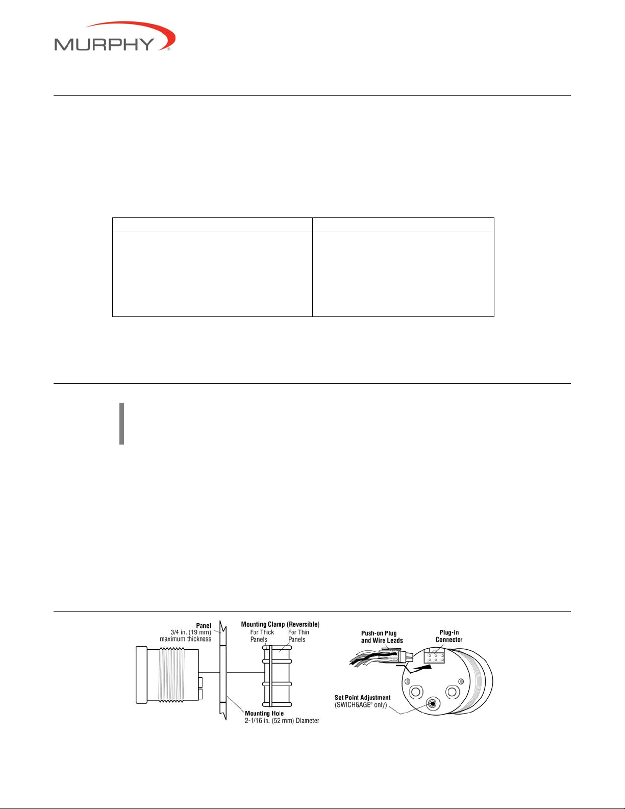
Gage Installation
In order to consistently bring you the highest quality, full featured products, we reserve the right to change our specifications and designs at any time.
MURPHY, the Murphy logo, and Swichgage
matter and illustrations, is copyright protected by Murphy Industries, Inc., with all rights reserved. (c) 2008 Murphy Industries, Inc.
®
are registered and/or common law trademarks of Murphy Industries, Inc. This document, including textual
Page 2
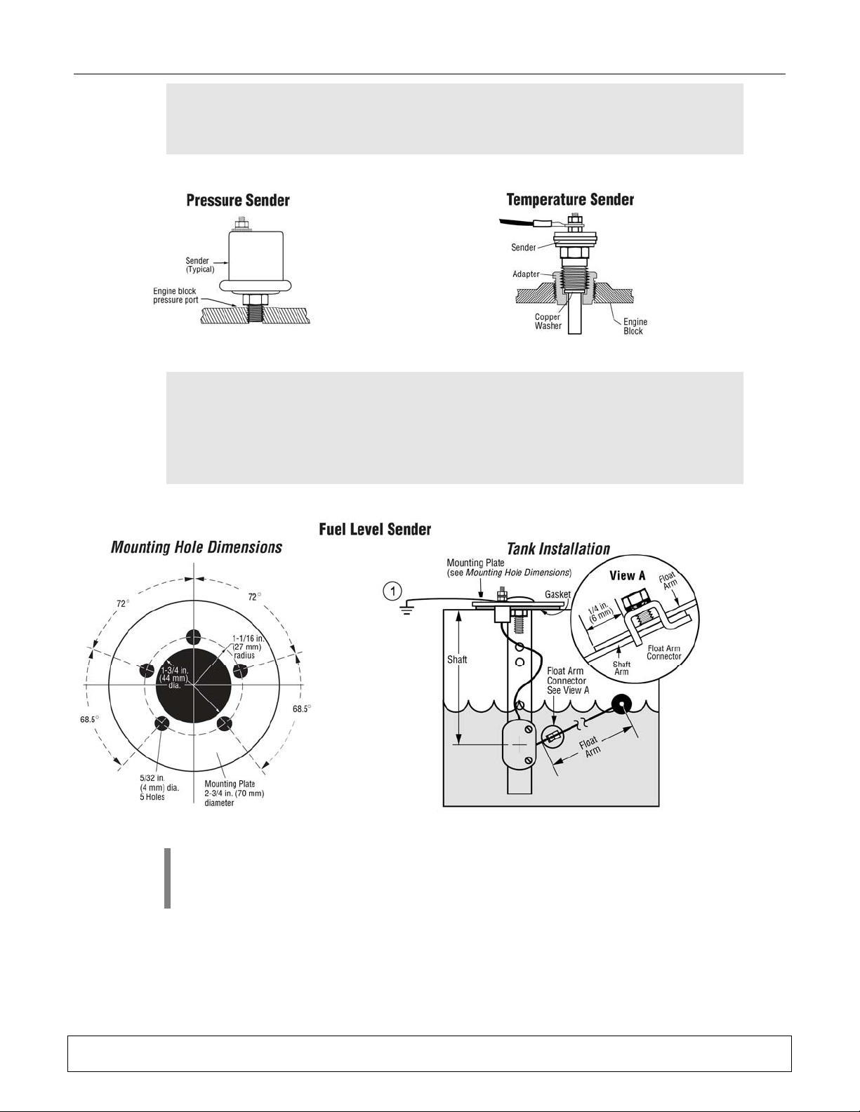
Sender Installation
CAUTION: Do not use sender body to tighten.
If sealant tape or pipe dope is used on the pressure sender, be sure
that the tape or dope does not plug the sender’s orifice.
Page 2 of 4.
CAUTION: Extreme caution must be used in handling or working on
or around the fuel tank. It must be worked on only in a WELL
VENTILATED area. Keep all flame and hot materials away from it.
Do not smoke while working on or around the tank. Avoid sliding or
dragging the tank, or other actions which may cause a spark.
NOTE:
another wire must be added from one of the sender mounting bolts to the battery ground
(negative post). See 1 in the ‘Tank Installation’ illustration above.
Warranty
may be viewed or printed by going to www.fwmurphy.com/support/warranty.htm
- A limited warranty on materials and workmanship is given with this FW Murphy product. A copy of the warranty
When installing the fuel sender in a non-metallic tank using a single wire sender,
Page 3

Basic Wiring
WARNING: Disconnect battery negative cable before wiring o r
service.
Sender Wiring
Page 3 of 4.
*Yellow wire is optional for gage illumination
and does not need to be connected for gage
to operate.
Swichgage Wiring
WARNING: DISCONNECT BATTERY NEGATIVE CABLE BEFORE
WIRING OR SERVICE.
CAUTION: Connecting full Battery potential to the brown wire can
damage the Swichgage. Shutdown circuit is rated for 300 mA
continuous, 900 mA inrush. Circuit rounds out at set point.
Warranty
may be viewed or printed by going to www.fwmurphy.com/support/warranty.htm
- A limited warranty on materials and workmanship is given with this FW Murphy product. A copy of the warranty
Page 4

Page 4 of 4.
CAUTION: Devices containing solid state components can be
damaged or caused to malfunction when used in systems which
incorporate inductive loads (e.g. relays, so le noid s, etc .) that can
generate voltage spikes.
To reduce the potential for this type of damage, instal l a flyback or
clamping diode across all inductive load s (see wir ing diagra m
below).
Use Murphy diode package 65-00-0343 or equiva lent . A typica l
diode is 1N4005 which is readily available from commercial
sources. Failures of this type are not covered by our Limited
Warranty.
Warranty
may be viewed or printed by going to www.fwmurphy.com/support/warranty.htm
- A limited warranty on materials and workmanship is given with this FW Murphy product. A copy of the warranty
 Loading...