

Page 1
Murphy CONNECT
Telematics for PowerCore Products
Operations Manual
Initial Release for U.S. Only
In order to consistently bring you the highest quality, full-featured products, we reserve the right to change our
specifications and designs at any time.
00-02-1165
2018-10-08
Section 40
Page 2

BEFORE BEGINNING INSTALLATION OF THIS MURPHY PRODUCT:
• Read and follow all installation instructions.
• Visually inspect this product before installation for any damage during
shipping.
• Disconnect all electrical power to the machine. Failure to do this before
welding can result in damage to the panel and/or its components.
• It is your responsibility to have a qualified technician install the unit and
make sure the installation conforms to local codes including but not
limited to double insulation and fire containment.
• Observe all Warnings and Cautions in each section of these instructions.
• The Murphy CONNECT product is a telemetry product designed for use
in industrial environments for remote monitoring and control when used
with Murphy’s PowerCore® family of controllers.
Contact Enovation Controls Technical Service if you have any questions or
concerns at: +1 918-317-4100.
IMPORTANT! Improper use and operation of electronic products can be
dangerous. It is required that point-of-operation guarding devices be installed
and maintained. All such devices must meet OSHA and ANSI Machine safety
standards. The manufacturer shall not accept any responsibility for installation,
application or safety of systems.
Section 40 ii 00-02-1165
2018-10-08
Page 3

Table of Contents
Introduction ................................................................................................................................. 5
Registering/Creating a New Account ...................................................................................... 6
New Site Setup ........................................................................................................................... 7
Adding New Site Personnel (Users) ........................................................................................ 9
Adding a New Child Site (Customer Site) ............................................................................. 11
Adding, Deleting, and Moving Equipment ............................................................................ 12
Site Equipment ......................................................................................................................... 14
Murphy CONNECT Specifications ......................................................................................... 22
Power Supply ............................................................................................................. 23
Inputs/Outputs ............................................................................................................ 23
Communications ........................................................................................................ 23
Connection ................................................................................................................. 23
Physical / Environmental ............................................................................................ 23
Section 40 3 00-02-1165
2018-10-08
Page 4
The CONNECT device can be used for remotely starting an engine when used in conjunction
with Murphy’s PowerCore controllers and start unexpectedly. Please be cognizant at all times
of hands and other objects that are in close proximity to the machine(s) being controlled as they
may commence operation suddenly and without warning
Section 40 4 00-02-1165
2018-10-08
Page 5

Introduction
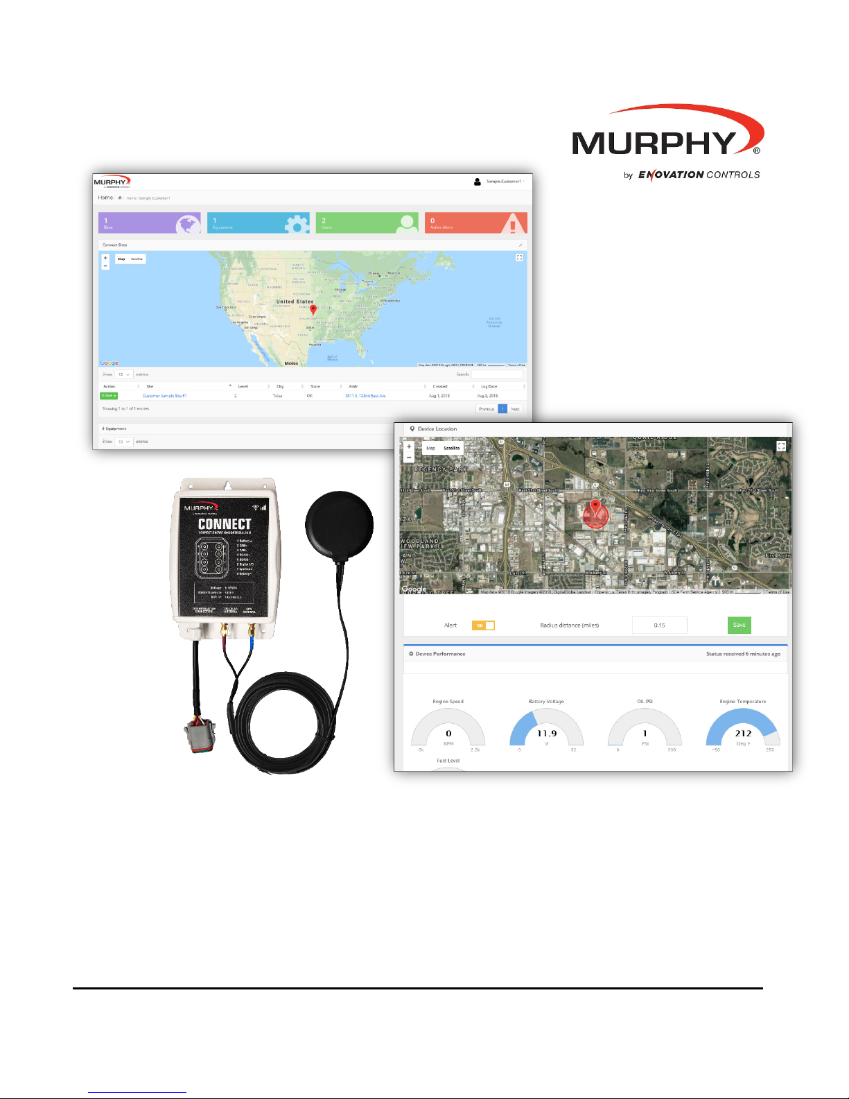
The Murphy CONNECT telematics unit provides simple and dependable communication power
for PowerCore panels and controllers. Murphy CONNECT is an easy, plug-and-play solution
for rental fleets, agriculture and pump systems as well as other PowerCore controller and
panel users wishing to automate or remotely monitor their engines.
The Murphy CONNECT unit is controlled from a cloud-based dashboard that provides secure
access from a computer or mobile device and is designed to be easy-to-use. LTE cell
technology provides worry-free data networking and allows you to stay connected from any
location. (LTE service required, 2-year service agreement included)
From the online dashboard, users can monitor their equipment's location using the unit's builtin GPS and set radius alerts for when it moves. Users can also view trends based on an
engine’s usage, and control engine starts and stops while adjusting throttle functions for the
engine and application. The cloud-based system is also multi-user and multi-unit capable for
companies that need to provide access across several units, locations or employees.
Built to survive the same harsh conditions as the PowerCore controllers, the IP67-rated
telematics unit remains operational alongside PowerCore products with rugged protection from
freezing temperatures, extreme heat, moisture and dust.
Murphy CONNECT provides astounding benefits by helping reduce costs, prevent downtime
and optimize efficiency with intelligent analytics, real-time alerts and warnings.
Section 40 5 00-02-1165
2018-10-08
Page 6
Registering/Creating a New Account
NOTE: In order to register/create a new account a Murphy CONNECT device
must be on hand that is not currently registered with another account.
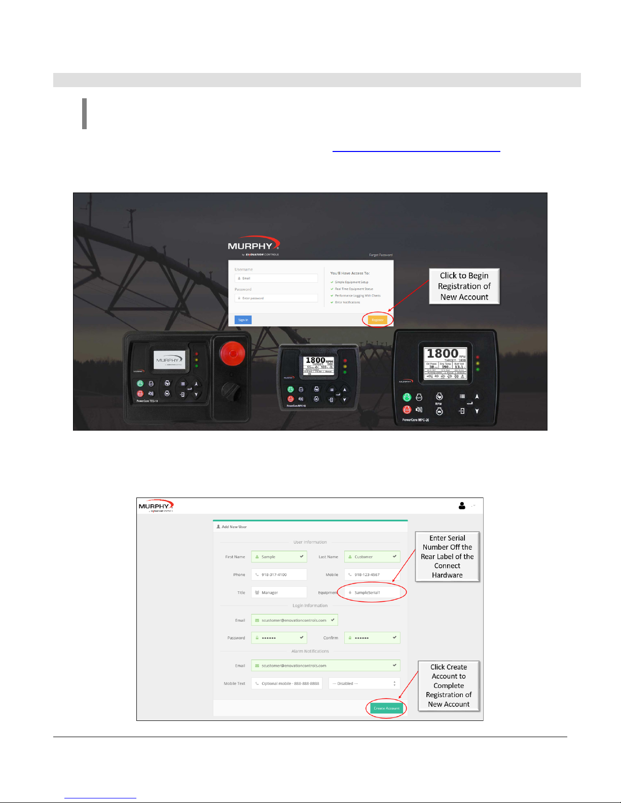
Begin by going to the Murphy CONNECT webpage connect.enovationcontrols.com. There is a
yellow box labeled Register in the lower right side of the Login Box. Click the Register button to
begin registering a new account.
After clicking the register button on the login page the site will direct you to an Add New User
registration page. Fill out all necessary boxes in the form before clicking the button Create
Account. In order to submit the request a new Murphy CONNECT device is required.
Section 40 6 00-02-1165
2018-10-08
Page 7
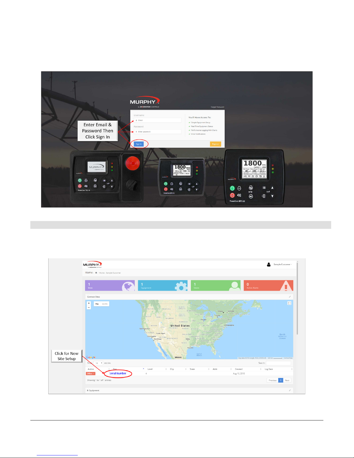
Once the new account is created the Sign In screen will be shown and allow the Admin to sign
in after filling out and submitting the registration form.
New Site Setup
Once registered and logged in, the Site will show the serial number of the unit used to register.
Click on the serial number under the map in the section labeled Connected Sites.
Section 40 7 00-02-1165
2018-10-08
Page 8
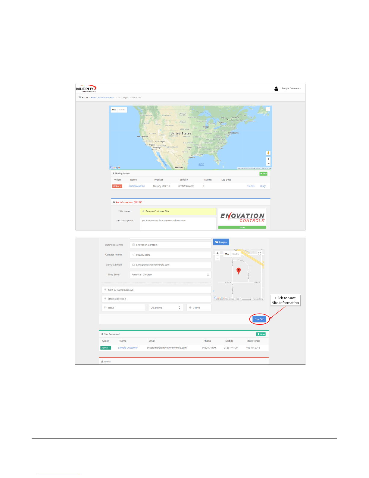
Once the serial number has been clicked the site will open another page for form completion.
This form will allow naming of the site, site description, business name, contact phone,
contact email, time zone selection, site logo/image to be loaded, site address and site
personnel to be added/edited.
Section 40 8 00-02-1165
2018-10-08
Page 9

Adding New Site Personnel (Users)
The CONNECT site allows for two different levels of users. The two levels are defined as Admin
and User for Site Personnel. To add a new User, select the site to which the user will be added.
Once on the site scroll down to the Site Personnel section and click New.
Fill in the new user information and click Create Account. Review the Admin and User sections
on the next page in order to decide which type of access to give the new user.
Section 40 9 00-02-1165
2018-10-08
Page 10

User Information
This section provides identity information for other users registered on the site to be viewed
and contacted if needed.
• Title: This setting is only used for reference as the number of site personnel grows.
• Billing: This setting is to alert the particular user for subscription renewal.
Login Information
This section provides the information for logging into the site with email and password. This
section also designates the level of access given to the user (User or Admin).
• User: User level users are able to login and see assigned sites as well as child sites,
view and control site equipment, view site personnel, acknowledge and delete alerts,
and view/export Device Status Trends.
• Admin: Admin level users are able to do everything the user level is able to do plus add
and remove users, move equipment from site to site, edit site information, add Child
Sites, turn on/off and change equipment Radius Alerts, load New CONNECT Firmware,
and perform equipment EZ Setup.
Alarm Notifications
This section provides the contact information to which alerts will be sent if desired when an
alert is present on the device/controller.
• Email: Enter the email address of any user desiring email notifications of existing
alarms.
• Mobile Text: Enter the mobile phone number of any user desiring mobile text
message notifications of existing alarms.
NOTE: Do not add a country code “1” for United States or place hyphens
in the number (e.g. 9183174100). Use the drop-down box to select the
carrier used for Text message notifications. Be sure to test the alert
notification to ensure the carrier setting is correct.
Section 40 10 00-02-1165
2018-10-08
Page 11

Adding a New Child Site (Customer Site)
The CONNECT web portal allows for companies to setup customer sites also referred to as
Child Sites. This allows one company to assist in managing the setup and contract renewals
for their customers. This also allows for customers to add personnel and their own child sites
to their main site if the locations are different.
Once the New Child Site button is clicked, a new window will open to fill out a form for the
child site similar to the form for the original site setup. Once the information is all entered, click
the Save Site button to save the site under the original company site.
Section 40 11 00-02-1165
2018-10-08
Page 12

Once the child site is established, the site will be shown as a child of the original company.
This site can now have new personnel (both users and admin) added to see and manage their
site.
NOTE: Be cognizant of viewing, editing, and deleting customer sites on
the original company site. All equipment and sites are live once showing
Online.
Adding, Deleting, and Moving Equipment
The Equipment section of the site shows how many pieces of equipment are assigned under
each site with device name, the product being assigned to (MPC-10/TEC-10 or MPC-20),
Serial Number of the unit, alarms, and when the unit started its online subscription.
Adding Equipment
Add equipment either to the home site and move (as detailed below) to the child site or add
directly to the child site.
Start by clicking New in in the Site Equipment section of the site as shown in the image below.
Section 40 12 00-02-1165
2018-10-08
Page 13

Once New is clicked a new page will open to enter the Equipment Name, Serial Number, IMEI,
and Type of Equipment the device is being used with. Enter all the required information and
click add to add a new piece of equipment to a site.
Moving Equipment
Under the Equipment Action category, the dropdown box allows users to edit, delete, or move
the device from site to site.
• Edit: Selecting Edit will open the Equipment page and allow editing of the equipment.
• Delete: Only delete the equipment if the module is no longer in service. If the equipment
is deleted it can be recovered by adding equipment back to a site as described above.
• Move: Selecting Move will allow moving the equipment from one site to another. This
requires child sites to move equipment from a home to a child.
Section 40 13 00-02-1165
2018-10-08
Page 14

Move: Select Move from drop down under Action column.
Move: Choose the Site the equipment is to be moved and press OK button.
Site Equipment
Site Equipment allows monitoring of the system as well as remote starts via Modbus with
remote throttle setpoint changes. The equipment page allows a user to see the Device
Location and set radius alerts, monitoring of the engine parameters, Remote Control for
start/stop and throttling, Alerts, Device Information, Device Status (Trends), and Device
Setup.
Section 40 14 00-02-1165
2018-10-08
Page 15

Device Location: This section shows the device location and allows an Admin level
user to set a radius alert for the equipment. When the equipment is moved out of the
established radius, it will send an alert notification to the personnel designated to
receive alert notifications.
Device Performance: This section displays the Admin-allowed active parameters to
be shown to all users in the EZ Setup section.
Section 40 15 00-02-1165
2018-10-08
Page 16

Device Remote Control: This section allows a user to place the PowerCore
controller in the manual or auto mode of operation. This section also allows for
remote Start/Stop and throttle control through Modbus to the controller.
Alerts: This section provides any active and inactive alerts that have not been
acknowledged and deleted.
Device Information: This section allows the name change of the device, shows the
controller the CONNECT device is used in conjunction with, the CONNECT serial
number, the active state the controller is in, the auto start setting chosen in the
controller, last log of the device, Device ID, CONNECT revision level, PowerCore
Version Application and Configuration numbers, and number of alarms. This section
also allows for the Admin to restart the CONNECT system, upgrade firmware of the
CONNECT system, and Save Device Information for the Equipment.
Section 40 16 00-02-1165
2018-10-08
Page 17

Device Status: This section provides the user with statistics from the last 24 hours
up to the past 3 months of parameters shown above in Device Performance. There is
also an option to run a custom timeframe and view Full Trends that can be zoomed
into 5 minute intervals.
Device Setup: This section is only available for Admin level users. This section
allows setting of the visual parameters on the equipment page, special alarming
functions, remote start/stop type and throttling settings, and showing the viewable
service reminders from the controller on the equipment page.
Section 40 17 00-02-1165
2018-10-08
Page 18

1) Device Setup Wizard (Equipment Configuration): This section allows
the admin to choose which device parameters are viewable on the
equipment page for all users.
2) Device Setup Wizard (Tier 4 Equipment Configuration): This section
allows the admin to choose Tier 4 gauges to be shown in the device
performance section and are viewable to all users with access to the
equipment.
Section 40 18 00-02-1165
2018-10-08
Page 19

3) Device Setup Wizard (Alarming Configuration): This section allows the
Admin to choose whether they would like an alert notification to be sent
when the device goes offline and when the controller is taken out of the
auto mode of operation.
4) Device Setup Wizard (Service Reminders): This section allows the Admin
to select whether the Service Reminders from the PowerCore controller are
to be shown on the Equipment page.
Section 40 19 00-02-1165
2018-10-08
Page 20

5) Device Setup Wizard (Control Selection): This section allows the Admin
to remotely set minimum and maximum engine speeds, choose the
Operating Mode for Auto Throttling of the system, and the maintain value
and deadband values for pressure, level, or flow throttling methods.
6) Device Setup Wizard (Review): This section allows the Admin to review
the changes in the Device Setup Wizard (EZ Setup) prior to saving or
saving/writing to device.
Section 40 20 00-02-1165
2018-10-08
Page 21

7) Device Setup Wizard (Save): This section allows the Admin to save
settings only to the webpage or Save and Write Drive to save settings to
the PowerCore controllers.
Section 40 21 00-02-1165
2018-10-08
Page 22

Troubleshooting
Murphy CONNECT has Wi-Fi communications which allow for minor troubleshooting of the
module. This section details how to log on and interpret the data.
To access the Wi-Fi for troubleshooting ensure the device has the appropriate power to the
unit. When the unit is powered on the unit can be found by searching for a new Wi-Fi
connection on the PC or smart device.
Wi-Fi Address: CONNECT_xxxx (the xxxx represent the last 4 digits of the MAC address of the
device connecting)
Password: Murphy (use Murphy only when required to login)
Once connected to the device Wi-Fi network, open the browser and type 192.168.6.1 into the
URL address to access the modem’s page (also shown on the CONNECT front label). The
page should resemble the image below and allow one to see the items listed below for
troubleshooting hardware and connectivity.
Application: States whether the application is running or not running. This should be running at
this stage
Version: Version of the CONNECT device
Connection: States whether the device is connected to a cellular network
Serial Number: Provides Serial Number of device. (Used to register device if device is
installed)
IMEI: Provides IMEI of device. (Used to register device if device is installed)
SIM: Provides SIM number.
Cell Signal: Provides range for cellular network. (0-6 = Poor, 7-15 = Okay, 15+ = Good)
GPS: States whether locked or not locked for GPS positioning.
Satellites: 1-2 will not allow a lock for GPS, 3+ allows locking for GPS location.
Latitude: Once GPS is locked, provides Latitude coordinates for last known location.
Longitude: Once GPS is locked, provides Longitude coordinates for last known location.
Section 40 22 00-02-1165
2018-10-08
Page 23

Murphy CONNECT Specifications
Power Supply
Operating Voltage: 9-36 VDC, reverse battery polarity protected
Max Voltage: -40 to +60 VDC
Power Consumption:
12 VDC: Transmitting: 265mA, Idle: 135mA, Off: 0.5mA (Using IGN to turn off),
On: ~175mA Avg.
24 VDC: Transmitting: 135mA, Idle: 90mA, Off: 0.5mA (Using IGN to turn off),
On: ~115mA Avg.
Inputs/Outputs
(1) Digital, Shared (Future Use)
Communications
(1) CAN: J1939 (Future Use)
(1) RS485: Modbus RTU
(1) Wi-Fi:2.4GHz 802.11 b/gn (Troubleshooting)
(1) Cellular (LTE)
(1) GPS (Location Services)
Connection
Connection:
8 Position: Amphenol AT06-08S
Antenna: SMA (Supplied 2 Wire Dual Cellular LTE and GPS)
Mating Connector:
8 Position: Amphenol AT04-08PA
Deutsch DT04-08PA
Physical / Environmental
Enclosure Material: Polycarbonate
Dimensions (WxHxD): 5.06 x 7.56 x 1.55 in. (129 x 192 x 39 mm)
IP Rating: IP67
Operating & Storage Temperature: -30°C to +80°C (-22°F to +176°F)
Vibration: 8.17 Grms (5-2000 Hz), 3-axes random
(Vibration specification was met without the use of rubber isolation mounts)
Shock: ±25G, 3 axes
(Vibration specification was met without the use of rubber isolation mounts)
Section 40 23 00-02-1165
2018-10-08
Page 24

 Loading...