

Page 1
Bulletin AT-95026B page 1 of 4
2 and 2-1/2 in. (51 and 64 mm) Dial
■
Corrosion Resistant Polycarbonate Case
■
Indicating Gage and Limit Switch
■
Switch Can Activate Alarms and/or Shut
Down Equipment
■
Critical/High Temperature Limit Switch
Is Visible and Adjustable (Most Models)
■
Contact(s) Isolated From Ground
Description
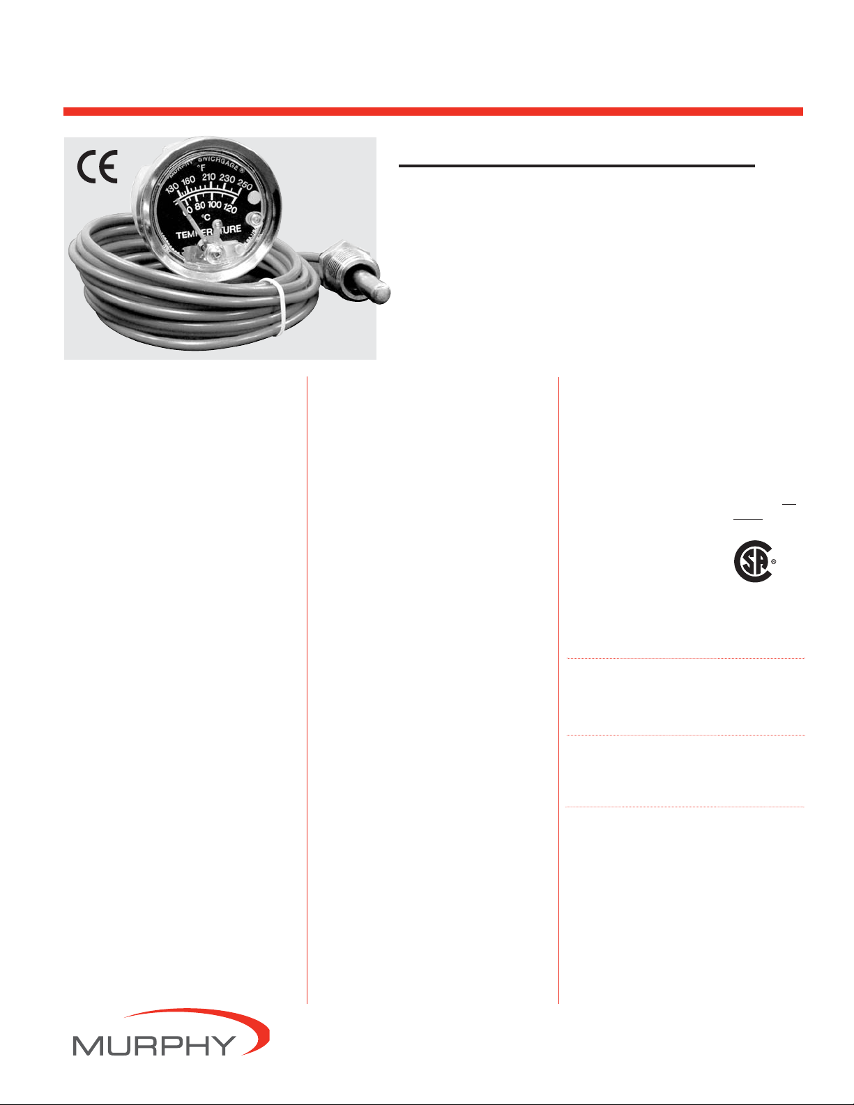
The A20 Series (2 inch/51 mm dial) and the A25
Series (2-1/2 inch/64 mm dial) SWICHGAGE
®
models are diaphragm-actuated, temperature-indicating
gages, with built-in electrical switches for tripping
alarms and/or shutdown devices.
Ranges are available from 32-120°F (0-45°C) thru
300-440°F (160-220°C).
All models of these rugged, built-to-last instruments
are fully sealed from the environment by the unique
combination of a polycarbonate case and lens, a polished stainless steel bezel, and O-ring seals.
These vapor/pressure actuated gages feature a sealed
capillary tube and a sensing bulb. When subjected to
heat, the liquid in the sensing bulb changes to vapor
creating pressure against a diaphragm mechanism.
The diaphragm translates this vapor pressure into a
mechanical gage reading.
For series A20T and A25T, the gage pointer acts as a
temperature indicator and as one switch pole which
completes a circuit when it touches the adjustable limit
contact. Contact(s) are isolated from ground. They have
self-cleaning motion to enhance electrical continuity.
Models A20TE and A25TE have internal snap-acting
SPDT switches.
Gage-only models, without contacts
(MURPHYGAGE®) are also available.
Applications
Applications for A20 and A25 Series temperature
SWICHGAGE®instruments include: engines and
equipment in Oil Field, Marine, Irrigation
,
Construction
and Trucking industries. Monitoring Engine Coolant
temperature, Crankcase Oil, Transmission Oil.
Specifications
Dial: White on black; U.S.A. standard scale is dual
scale °F/°C; others available.
Case: Glass filled/Polycarbonate, corrosion-resis-
tant; steel mounting clamp included. Bezel:
Polished stainless steel, standard; others
are available.
Pointer: Tempered nickel silver; red tip.
Lens: Polycarbonate, high-impact.
Sensing Element: Beryllium copper diaphragm.
Capillary: PVC armored copper; 4 ft. (1.2 m).
*
Stainless steel armor optional.
Sensing Bulb: Copper.
*
Gage Accuracy: See accuracy chart, on page 2.
Maximum Temperature: See Temperature Ranges
and Factory Settings table on page 2.
Adjustable Limit Contact (A20T and A25T):
SPST contact; pilot-duty only, 2 A @ 30 VAC/
VDC; isolated from case ground. Normally Closed
when the high limit is met. Normally Open when
pointer is in normal operating range. Contacts are
gold flashed silver.
Limit Contact Adjustment: by a 1/16 in. hex
wrench thru 100% of the scale.
Wiring: A20T: Number 4 screw terminals;
A25T: Number 6 screw terminals.
Snap-Switch Rating (A20TE and A25TE):
SPDT, 3 A@ 30 VDC inductive; 4 A @
125 VAC inductive.
Wiring: A20TE: Number 4 screw terminals;
A25TE: Number 6 screw terminals.
Unit Weight: A20 Series: 11.9 oz. (0.370 kg).
A25 Series Models: 13.3 oz. (0.413 kg).
Unit Dimensions: A20 Series: 4-3/4 x 4-3/4 x 3 in.
(121 x 121 x 76 mm). A25 Series Models: 4-3/4 x
4-3/4 x 2-3/4 in. (121 x 121 x 70 mm).
Base Models
Coolant or Oil Temperature
A20T and A25T Series SWICHGAGE
®
For these models the gage pointer makes with an
adjustable contact to complete a pilot-duty circuit.
A20TL and A25TL SWICHGAGE
®
For use on Ford Worldwide engines. Supplied with
special sensing bulb.
A20TE and A25TE SWICHGAGE
®
A20TE (was A20ESR) and A25TE (was A25ESR).
Models with internal SPDT snap-switches, instead
of the single pole/pointer contact(s). When the
switch closes on rising temperature, it becomes Set.
As temperature decreases the switch Resets
.
Model A25TE is CSA listed for
non-hazardous areas. Model
A25TE-EX is CSA listed for
Class I, Division 1, Groups
C & D hazardous areas.
A20TABS and A25TABS SWICHGAGE
®
Same as 20 and 25T with internal SPDT snapswitch for pre-alarm.
Cylinder Head Temperature
A20TH and A25TH SWICHGAGE
®
A20TH (was A20TL8133) and A25TH (was
A25TL8133). For use on Air Cooled engines.
Gage–Only Models
A20TG and A25TG MURPHYGAGE
®
Gage without contact(s).
*
For optional capillary lengths, engine adapters, sensing bulbs
and range combinations, see Murphy bulletin T-8428B.
**
Products covered by this bulletin comply with EMC Council
directive 89/336/EEC regarding electromagnetic
compatibility except as noted.
A20T Series
shown
**
AT-95026B
Revised 08-05
Catalog Section 10
A20 and A25 Series
Temperature SWICHGAGE
®
Page 2
Bulletin AT-95026B page 2 of 4
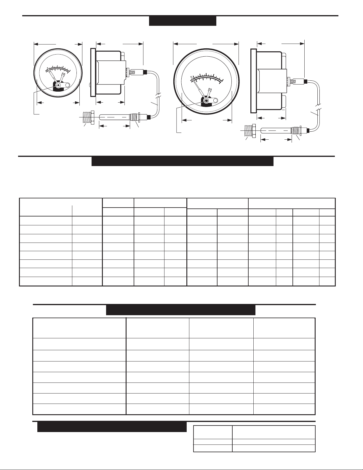
Dimensions
A20 Series Models (typical) A25 Series Models (typical)
Ranges Available
Dual Scale Dial Single Scale
°Fahrenheit (°Celsius) °Celsius only
Std. Settings*
°F (°C) °C only
Max. Temp.
°F (°C)
20TABS and 25TABS Settings
Alarm** Shutdown
°F (°C) °C only °F (°C) °C only
Hi/Lo Settings
Low High
°F (°C) °F (°C)
32 – 160 (0 – 71) 0 – 70 215 (102) 150 (66) 66 32 (0) 150 (66) 140 (60) 60 150 (66) 66
32 – 120 (0 – 49) –– 185 (85) 110 (43) –– 32 (0) 110 (43) 100 (38) –– 110 (43) ––
130 – 220 (54 – 104) 45 – 100 260 (127) 210 (99) 85 160 (71) 210 (99) 200 (93) 80 210 (99) 85
130 – 250 (54 – 121) 50 – 120 310 (154) 210 (99) 97 160 (71) 210 (99) 200 (93) 95 210 (99) 100
160 – 320 (71 – 160) 70 – 160 370 (192) 300 (149) 150 200 (93) 300 (149) 290 (143) 145 300 (149) 150
140 – 300 (60 – 149) 60 – 140 340 (173) 275 (135) 130 200 (93) 275 (135) 265 (129) 125 275 (135) 130
180 – 350 (82 – 177) –– 400 (209) 330 (166) –– 240 (116) 330 (166) 320 (160) –– 330 (166) ––
300 – 440 (149 – 227) –– 500 (260) 400 (204) –– 300 (149) 400 (204) 390 (199) –– 400 (204) ––
* Standard setting for A20T, A25T, A20TE and A25TE models.
** SPDT snap-switch is the alarm switch.
NOTES
1. Values in ( ) are mathematical conversions from °F to °C–they do not reflect actual second scale range. U.S.A. standard scale is °F/°C.
2. For models A20TE and A25TE; the switch trip point cannot be set at either the low or high extreme of the scale. The trip point must allow for the reset differen-
tial.
3. For adjustable switch models, the trip point is adjustable only over the upper half of the scale.
Temperature Ranges and Factory Settings
Temperature Accuracy Chart
32 to 120°F (0 to 49°C) ± 12°F (± 6°C) ± 5°F (± 2.4°C) ± 6°F (± 3°C)
32 to 160°F (0 to 71°C) ± 20°F (± 10°C) ± 8°F (± 4.4°C) ± 7°F (± 4°C)
130 to 220°F (54 to 104°C) ± 6°F (± 3°C) ± 3°F (± 1.6°C) ± 4°F (± 2°C)
130 to 250°F (54 to 121°C) ± 9°F (± 5°C) ± 5°F (± 2.4°C) ± 4°F (± 2°C)
Temperature Range Lower
1
/3 of Scale Middle 1/3 of Scale Upper 1/3 of Scale
140 to 300°F (60 to 149°C) ± 10°F (± 5.2°C) ± 6°F (± 3°C) ± 5°F (± 2.4°C)
160 to 320°F (71 to 160°C) ± 10°F (± 5.2°C) ± 5°F (± 2.4°C) ± 5°F (± 2.4°C)
180 to 350°F (82 to 177°C) ± 12°F (± 6°C) ± 5°F (± 2.4°C) ± 5°F (± 2.4°C)
300 to 440°F (149 to 227°C) ± 9°F (± 5°C) ± 5°F (± 2.4°C) ± 4°F (± 2°C)
RANGE MAXIMUM PROCESS TEMPERATURE
≤250° (120°) 120% OF FULL SCALE
300° (140°) 350° (198°)
≥320° (160°) 120% OF FULL SCALE
MAXIMUM AMBIENT TEMPERATURE: -40° (-40°) thru 150° (66°)
Maximum Temperature
2-1/4 in.
(57 mm)
W
S
I
C
H
Y
G
H
A
P
G
R
U
M
160
130
60
TEMPERATURE
E
°F
®
210
230
250
100
80
120
°C
2-1/16 in. (53 mm)
Mounting hole dia.
Contact
Adjustment
1/16 in. hex
1/2 NPT
Adapter Nut
†
Standard combinations. See Murphy bulletin T-8428B for optional sensing bulb, engine adaptors and capillary combinations.
†
2-1/2 in.
(64 mm)
Mounting
Clamp
1-27/64 in.
(36 mm)
1-1/2 in.
(38 mm)
Sensing Bulb
Capillary
4 ft. (1.2 m)
†
†
long
5/8-18 U.N.F.
Union Nut
2-29/32 in.
(74 mm)
Y
H
P
R
U
M
160
130
80
60
TEMPERATURE
2-11/16 in. (68 mm)
Mounting hole dia.
Contact
Adjustment
1/16 in. hex
S
°F
210
°C
W
100
2-1/2 in.
(64 mm)
I
C
H
G
A
G
E
®
230
250
120
Mounting
Clamp
1-11/32 in.
(34 mm)
†
Capillary
4 ft. (1.2 m)
long
1-1/2 in.
1/2 NPT 5/8-18 U.N.F.
Adapter Nut
†
(38 mm)
Sensing Bulb
†
Union Nut
Page 3

Bulletin AT-95026B page 3 of 4
Pre-Alarm Using A20/A25TABS
Typical Internal Wiring Diagrams
The A20TABS and A25TABS features a standard limit contact for equipment
shutdown on high temperature. It also has an internal SPDT snap-switch to signal an alarm before shutting down. When the snap-switch trips (preset point), on
rising temperature, the switch completes a circuit to activate an alarm. If the
temperature continues to increase, the face-adjustable pointer contact will make
and the shutdown circuit will be completed (see the typical diagram below for
reference). The front contact shutdown limit setting (which is adjustable) and
the snap-switch are preset at the factory. Refer to “Temperature Ranges and
Factory Settings” table on opposite page for settings. For alternative alarm
before shutdown, see Magnetic Switch model 760A or 761APH.
_
+
Battery
A20TABS
SWICHGAGE
®
Alarm Before
Shutdown
MINI-SIREN
®
Opens circuit to
shutdown engine.
Shutdown Device
or Ignition Circuit
518PH
TATTLETALE
®
HIGH
C
N. C.
N. O.
ABS
GNCRSW1 SW2
B
Magnetic Switch
INDUCTIVE AND HIGH CURRENT LOADS REQUIRE THE USE OF A
MAGNETIC SWITCH. The SWICHGAGE®contacts are for light-duty elec-
trical switching to operate alarms or control devices. Murphy manufactures the
Magnetic Switch for protection of the pilot-duty SWICHGAGE
®
limit contacts.
TATTLETALE®Magnetic Switches show the cause of shutdown for applications that include: capacitor discharge or magneto ignitions, battery systems and
electric motor driven equipment. Typical wiring diagrams are shown below.
C
HIGH
N. C.
N. O.
C
HIGH
N. C.
N. O.
LOW
HIGH
C
N. C.
N. O.
ABS
P
L
H
C
N. C.
N. O.
P
L
H
C
N. C.
N. O.
P
L
H
C
N. C.
N. O.
RESET
SET
HIGH
HIGH
HIGH
SETRESETSETRESETSETRESET
LOW HIGH
LOW
C
N. C.
N. O.
P
L
H
C
N. C.
N. O.
P
L
H
C
N. C.
N. O.
A20T A20T-HL A20TABS A20TE
A25T
A25T-HL
A25TABS
A25TABS-HL A25TE
Pointer shown in the shelf position. Pointer type contact rating: pilot-duty 2 A @ 30 VAC/VDC resistive.
Snap-acting switch rating: 3 A @ 30 VDC inductive. 4 A @ 125 VAC inductive.
A20T Temperature
SWICHGAGE
®
HIGH
C
N. O.
Energized To Run Devices
117 Magnetic Switch
C
S
B
Battery
_
+
LOW
N. C.
A20P Pressure
SWICHGAGE
®
N.O. SWICHGAGE®
instruments
C
N.C. switches option
A20T Temperature
SWICHGAGE
®
HIGH
C
N. O.
Energized To Run Devices
518PH TATTLETALE
GNCRSW1 SW2
®
B
_
Battery
+
Page 4

Bulletin AT-95026B page 4 of 4
How to Order
To order, use the diagram below. List options in ascending alphabetical order (A-Z). Example: A20T-B1-250-4.
Range
††
Base Model
A20T
A20TL
A20TO
A20TE
A20TABS
A20TB
A20TH
____ – ____ – ____ – ____ – ____
Single scale (°C)
70C = 0-70°C
100C = 45-100°C
120C = 50-120°C
140C = 60-140°C
160C = 70-160°C
Dual scale (°F/°C)
°F °C
120 = 32-120 0-49
160 = 32-160 0-71
220 = 130-220 54-104
250 = 130-250 60-121
300 = 140-300 60-149
320 = 160-320 71-160
350 = 180-350 82-177
440 = 300-440 149-227
Temperature Capillary Armor Type
and Length
Capillary Armor Type
Blank = PVC armor, copper capillary
S = Stainless steel armor, copper capillary
Capillary Length (specify after capillary type;
example: “S4”)
4 = 4 ft. (1.2 m)
Specify other length = Available in 2 ft. increments
thru 20 ft.; 5 ft. increments above 20 ft. (0.5 m.
increments from 1.5–10 m.; 2 m. increments thru
34 m. Specify “M” following length, i.e. 1.5M.)
A20TG
A25T
A25TL
A25TE
A25TABS
A25TH
A25TG
††
Consult factory for availability of dials other than °F/°C. Select scale
so your normal operating temperature is in the upper half of the scale.
Options
†
B1 = Black bezel
EX = Explosion-proof (CSA Listed for
Class I, Div. 1, Groups C & D)*
EL = Explosion-proof less case
HL = High and low contacts
K = Knob adjusting face contact
OS = Oil sealed (Silicone Oil)
UA = Temperature bulb style “A” (10-05-0166)
UB = Temperature bulb style “B” (10-01-0061)
UC = Temperature bulb style “C” (10-01-0060)
UD = Temperature bulb style “D” (10-00-0286)
UE = Temperature bulb style “E” (10-01-0084)
UF = Temperature bulb style “F” (10-00-0577)
UG = Temperature bulb style “G” (10-00-0578)
UH = Temperature bulb style “H” (10-00-2466)
UJ = Temperature bulb style J (10051153)
UK = Temperature bulb style K (10054886)
†
Options not available on all models or configurations.
*
A25TE-EX only is CSA listed for hazardous locations.
**
This option is not covered by the CE mark.
Illumination – Order Separately
A20 Series:
Clamp Lite Assembly; 12 V= 05702176; 24 V= 05702177
A25 Series:
N/A.
Adapter Nuts
†††
Metric
M10 = 10 mm x 1.5
M12 = 12 mm x 1.5
M14 = 14 mm x 1.5
M16 = 16 mm x 1.5
M18 = 18 mm x 1.5
M20 = 20 mm x 1.5
M22 = 22 mm x 1.5
M24 = 24 mm x 1.5
1/8 = 1/8-27 NPT
1/4 = 1/4-18 NPT
3/8 = 3/8-18 NPT
3/8B = 3/8-19 BSPT
3/8K = 3/8 NPSF
– = 1/2-14 NPT
††††
1/2B = 1/2-BSPT
1/2K = 1/2 NPSF
5/8 = 5/8-18 UNF
3/4 = 3/4-14 NPT
3/4U = 3/4-16 UNF
7/8 = 7/8-9 UNC
†††
Specific adapter nut must
match the sensing bulb.
††††
Standard.
Warranty
A limited warranty on materials and workmanship is given with
this FW Murphy product. A copy of the warranty may be viewed
or printed by going to www.fwmurphy.com/support/warranty.htm
CONTROL SYSTEMS & SERVICES DIVISION
P.O. Box 1819; Rosenberg, Texas 77471; USA
+1 281 633 4500 fax +1 281 633 4588
e-mail sales@fwmurphy.com
INDUSTRIAL PANEL DIVISION
P.O. Box 470248
Tulsa, Oklahoma 74147 USA
+1 918 317 4100 fax +1 918 317 4266
e-mail sales@fwmurphy.com
FRANK W. MURPHY, LTD.
Church Rd.; Laverstock, Salisbury SP1 1QZ; U.K.
+44 1722 410055 fax +44 1722 410088
e-mail sales@fwmurphy.co.uk
www.fwmurphy.co.uk
MURPHY DE MEXICO, S.A. DE C.V.
Blvd. Antonio Rocha Cordero 300, Fracción del Aguaje
San Luis Potosí, S.L.P.; México 78384
+52 444 8206264 fax +52 444 8206336
Villahermosa Office +52 993 3162117
e-mail ventas@murphymex.com.mx
www.murphymex.com.mx
In order to consistently bring you the highest quality, full featured products, we reserve the right to change our specifications and designs at any time.
FW Murphy
P.O. Box 470248
Tulsa, Oklahoma 74147 USA
+1 918 317 4100 fax +1 918 317 4266
e-mail sales@fwmurphy.com
www.fwmurphy.com
Printed in U.S.A.
 Loading...