

MURO VL71-FLR User Manual
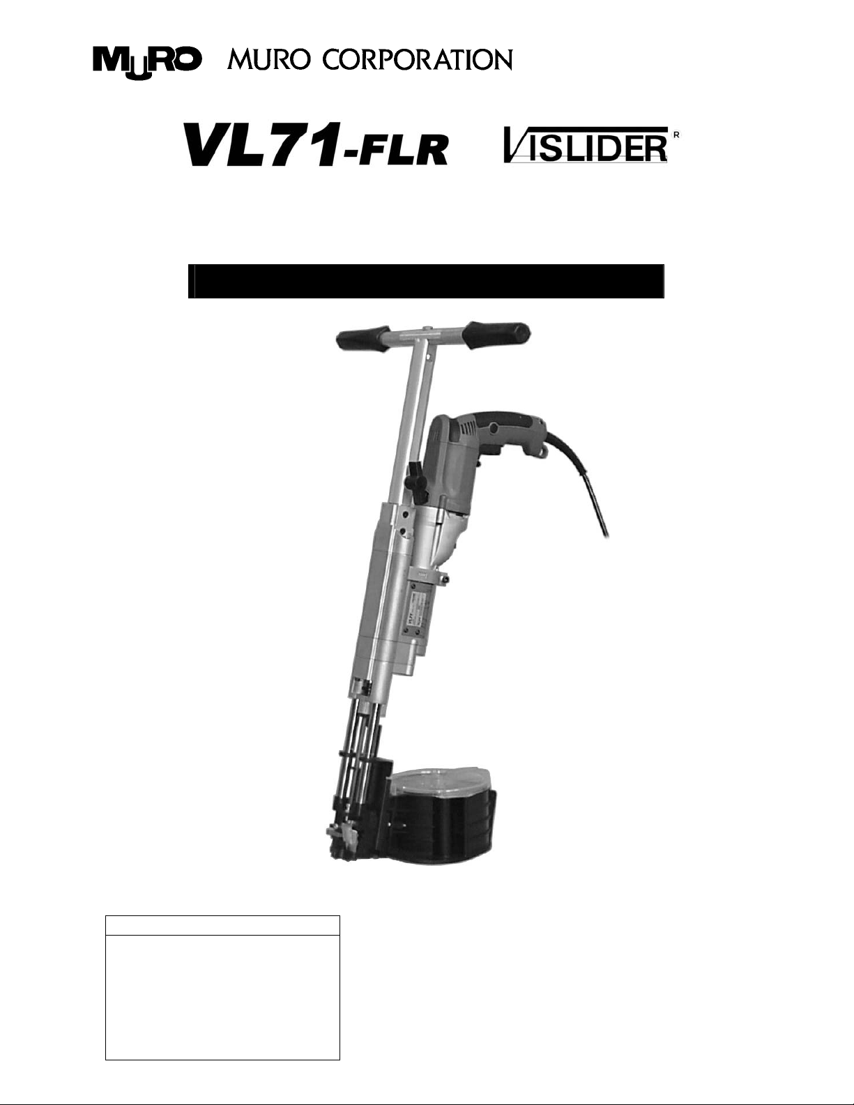
Heavy Duty Auto Feeding Screwdriving Tool
Instruction manual (with warranty card)
Table of contents
Safety precautions
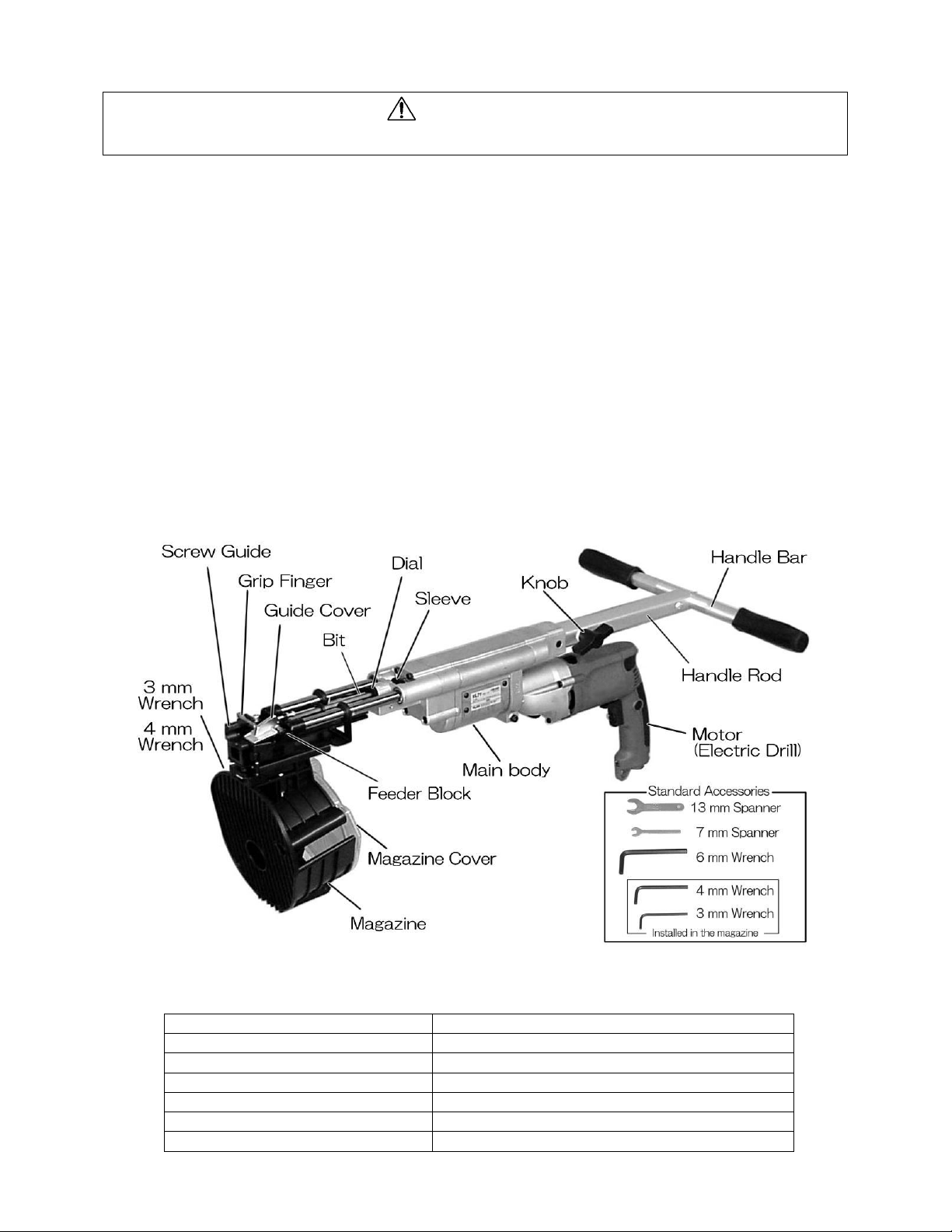
Parts designation
Specifications
Assembling VISLIDER
Loading VISROPE
Driving screws
Maintenance and inspection
1
1
1
2
3 - 5
5 - 6
7
Safety precautions
WARNING
Denotes risk of personal injury, loss of life or damage to the tool
In case of nonobservance of the instructions in this manual.
Before use, be sure to carefully read the instructions.
Read the related Drill instruction manual, too.
Be sure to wear protective goggles during work.
Be sure to wear a dust-proof mask during work.
Depending on the work environment, wear ear
protectors, hardhat, working shoes, and other safety
gear.
Be sure to use the specified Adaptor Kit that is
dedicated to your Drill model.
Be sure to use the specified "VISROPE" connecting
screws.
Ensure solid footing and hold yourself in a safety-first
position.
Wear clothes proper for work.
Keep the workplace in order and wel l lit.
When working in an elevated place, make sure there is
nobody beneath. Be very careful not to let this unit and
Parts designation
screws fall.
Never direct this unit toward anybody.
Never keep your hands, feet and head clos e to the tip
(screw outlet) of the unit during work.
Keep the unit away from open fire and flame.
Do not use the unit near volatile, flammable substances
such as gasoline, thinner, gas, paint, and adhesive. The
unit may catch fire or explode.
Do not use the unit in rain, or water-splashed, wet or
humid area. Do not leave the unit in rain, either.
Keep the unit, accessories and consumable parts
without reach of children.
For after-use handling, refer to "Maintenance and
inspection".
Handle the unit with enough care. Dropping or hitting
may result in malfunction.
Keep these instructions in the safe place.
Specifications
Heavy Duty Auto Feeding Screwdriving Tool
Overall length (including the handle) Approx. 885 -1,005 mm * For 45 mm screw length
Weight (without the motor) Approx. 5.4 kg
Max. driving depth Approx. 8 mm
Applicable screw length 32 – 76 mm (1-1/4” to 3”)
Applicable screw head diameter DIA 10 – 13 mm
Applicable screw nominal di a m eter DIA 5 – 6 mm
Electrical specifications See the motor instruction manual
1
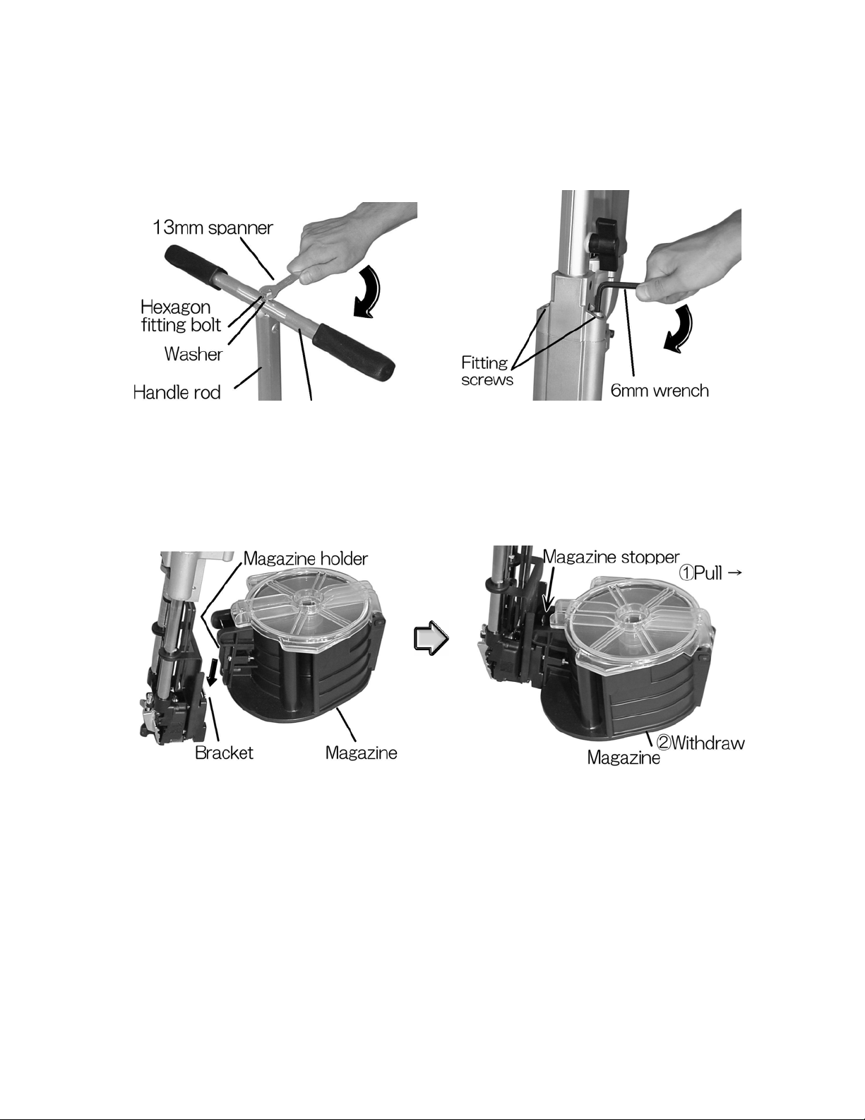
Assembling VISLIDER
1.
Assembly and fitting of rod handle
Remove the hexagon fitting bolt and the washer
from the handle rod. To the handle rod, fit the
handle bar, the washer an d t he he x ago n b olt in th is
order. Tighten the hexagon fitting bolt using the
13mm spanner.
Mount the ass emble d rod ha ndle o n the re ar of t he
main body. Tighten the two fitting screws using
the 6mm wrench.
2. Fitting and removal of magazine
To fit the magazine, insert the magazine holder
into the bracket at top end of the main body until
it clicks.
To remove the magazine, withdraw it while pulling
the magazine stopper with fingers.
2
 Loading...