

Murex Tradesarc 200 Instruction Manual
GB
Valid for serial no. 827--xxx--xxxx0460 473 074 090605
Tradesarc 200
Instruction manual and
spare parts list

-- 2 --
TOCe
Rights reserved to alter specifications without notice.
1 DIRECTIVE 3........................................................
2SAFETY 3...........................................................
3 INTRODUCTION 4...................................................
3.1 Equipment 5................................................................
3.2 Control panel 5.............................................................
4 TECHNICAL DATA 5.................................................
5 INSTALLATION 6....................................................
5.1 Location 6..................................................................
5.2 Mains power supply 6........................................................
6 OPERATION 7.......................................................
6.1 PFC -- Power factor correction 7..............................................
6.2 Connections and control devices 7............................................
6.3 Connection of welding and return cable 7.......................................
6.4 Overheating protection 7.....................................................
6.5 MMA welding 8.............................................................
6.6 TIG welding 8...............................................................
6.7 Remote control unit 9........................................................
7 MAINTENANCE 9....................................................
7.1 Inspection and cleaning 9....................................................
8 FAULT--TRACING 10..................................................
8.1 Fault codes 10...............................................................
9 CONTROL PANEL 10..................................................
10 MMA WELDING 12....................................................
10.1 Settings 12..................................................................
10.2 Symbol and Function explanations 12...........................................
10.3 Hidden functions MMA welding 13..............................................
11 TIG WELDING 13.....................................................
11.1 Settings 13..................................................................
1 1.2 Symbol and Function explanations 14...........................................
12 WELDING DATA MEMORY 14..........................................
13 FAULT CODES 15.....................................................
13.1 Fault code descriptions 15.....................................................
14 ORDERING SPARE PARTS 16..........................................
15 DISMANTLING AND SCRAPPING 16...................................
DIAGRAM 18............................................................
SPARE PARTS LIST 21...................................................
ACCESSORIES 26.......................................................

-- 3 --
bh37d1em
1DIRECTIVE
DECLARATION OF CONFORMITY
Murex Welding Products Ltd, EN8 7TF England, gives its unreserved guarantee that welding power
source Tradesarc 200 from serial number 827 (2008 w 27) are constructed and tested in compliance
with the standard EN 60974--1 and EN 60974--10 (Class A) in accordance with the requirements of
directive (2006/95/EC) and (2004/108/EEC).
-- -- -- -- -- -- -- -- -- -- -- -- -- -- -- -- -- -- -- -- -- -- -- -- -- -- -- -- -- -- -- -- -- -- -- -- -- -- -- -- -- -- -- -- -- -- -- -- -- -- -- -- -- -- -- -- -- -- -- -- -- -- -- --------
Kent Eimbrodt
Global Director
Equipment and Automation
On behalf of Murex Welding Products Ltd.
Laxå 2008--08--28
Manufactured by ESAB AB, Welding Equipment
SE--695 81 Laxå Sweden
2SAFETY
Users of welding equipment have the ultimate responsibility for ensuring that anyone who works on
or near the equipment observes all the relevant safety precautions. Safety precautions must meet
the requirements that apply to this type of welding equipment. The following recommendations
should be observed in addition to the standard regulations that apply to the workplace.
All work must be carried out by trained personnel well--acquainted with the operation of the welding
equipment. Incorrect operation of the equipment may lead to hazardous situations which can result
in injury to the operator and damage to the equipment.
1. Anyone who uses the welding equipment must be familiar with:
S its operation
S location of emergency stops
S its function
S relevant safety precautions
S welding
2. The operator must ensure that:
S no unauthorized person is stationed within the working area of the equipment when it is
started up.
S no--one is unprotected when the arc is struck
3. The workplace must:
S be suitable for the purpose
S be free from drafts
4. Personal safety equipment
S Always wear recommended personal safety equipment, such as safety glasses, flame--proof
clothing, safety gloves.
S Do not wear loose--fitting items, such as scarves, bracelets, rings, etc., which could become
trapped or cause burns.
5. General precautions
S Make sure the return cable is connected securely.
S Work on high voltage equipment may only be carried out by a qualified electrician.
S Appropriate fire extinquishing equipment must be clearly marked and close at hand.
S Lubrication and maintenance must not be carried out on the equipment during operation.
CAUTION!
This product is solely intended for arc welding.
GB
-- 4 --
bh37d1em
WARNING
Read and understand the instruction manual before installing or operating.
Arc welding and cutting can be injurious to yourself and others. Take precausions when welding.
Ask for your employer’s safety practices which should be based on manufacturers’ hazard data.
ELECTRIC SHOCK - Can kill
S Installand earth the welding unit in accordance withapplicablestandards.
S Do not touch live electrical parts or electrodes with bare skin, wet gloves or wet clothing.
S Insulateyourselffromearthand the workpiece.
S Ensure your working stance is safe.
FUMES AND GASES - Can be dangerous to health
S Keep your head out of the fumes.
S Use ventilation,extraction at the arc, or both, to take fumes and gases away from your breathing zone
and the general area.
ARC RAYS - Can injure eyes and burn skin.
S Protectyour eyes and body. Use the correct welding screen and filterlens and wear protective
clothing.
S Protectbystanders with suitablescreens or curtains.
FIRE HAZARD
S Sparks (spatter)can cause fire. Make sure therefore that there are no inflammable materialsnearby.
NOISE - Excessive noise can damage hearing
S Protectyour ears. Use earmuffs or other hearing protection.
S Warnbystanders of the risk.
MALFUNCTION - Call for expert assistance in the event of malfunction.
PROTECT YOURSELF AND OTHERS!
Murex can provide you with all necessary welding protection and accessories.
WARNING!
Do not use the power source for thawing frozen pipes.
CAUTION!
Read and understand the instruction manual before
installing or operating.
CAUTION!
Class A equipment is not intended for use in residential locations where
the electrical power is provided by the public low--voltage supply
system. There may be potential difficulties in ensuring electromagnetic
compatibility of class A equipment in those locations, due to conducted
as well as radiated disturbances.
3 INTRODUCTION
Tradesarc 200 is a welding current power source intended for use with coated
electrodes (MMA welding) and TIG welding.
Accessories for the product can be found on page 26.
GB

-- 5 --
bh37d1em
3.1 Equipment
Tradesarc 200 issuppliedwitha3mweldingcable,returncable,3mmainscable
and an instruction manual for power source and control panel.
3.2 Control panel
Welding process parameters are controlled via the control panel, see page 10.
4 TECHNICAL DATA
Tradesarc 200
Mains voltage 230 V, 1 μ 50/60 Hz
Primary current
I
max
TIG
I
max
MMA
24 A
25 A
Mains supply Z
max
0.31 ohm
No--load power demand when in the
energy--saving mode, 6.5 min. after welding
30 W
Voltage/current range, MMA 4 A /20 V -- 170 A /26.8 V
Voltage/current range TIG 3 -- 220 A
Permissible load at MMA
25% duty cycle
60% duty cycle
100% duty cycle
170 A / 26.8 V
130 A / 25.2 V
110A/24.4V
Permissible load at TIG
20% duty cycle
60% duty cycle
100% duty cycle
220 A / 18.8 V
150 A / 16.0 V
110A/14.4V
Power factor at maximum current
TIG
MMA
0.99
0.99
Efficiency at maximum current
TIG
MMA
75%
81%
Open--circuit voltage MMA / TIG
without VRD
with VRD
55 -- 60 V
<35V
Operating temperature -- 1 0˚C-- +40˚ C
Transportation temperature -- 2 0˚C-- +55˚ C
Constant A--weighted sound pressure <70dB
Dimensions, l x b x h 418 x 188 x 208 mm
Weight 8.3 kg
Enclosure class IP 23
Application class
Duty cycle
The duty cycle refers to the time as a percentage of a ten--minute period that you can weld at a certain load without overloading. The duty cycle is valid for 40˚C.
The duty cycle is valid for 40˚C.
Enclosure class
The IP code indicates the enclosure class, i. e. the degree of protection against penetration by solid
objects or water. Equipment marked IP23 is designed for indoor and outdoor use.
GB
-- 6 --
bh37d1em
Application class
The symbol indicates that the power source is designed for use in areas with increased
electrical hazard.
Mains supply, Z
max
Maximum permissible line impedance of the network in accordance with IEC 61000--3--1 1.
5 INSTALLATION
The installation must be executed by a professional.
Note!
Mains supply requirements
High power equipment may, due to the primary current drawn from the mains supply, influence the
power quality of the grid. Therefore connection restrictions or requirements regarding the
maximum permissible mains impedance or the required minimum supply capacity at the interface
point to the public grid may apply for some types of equipment (see technical data). In this case it
is the responsibility of the installer or user of the equipment to ensure, by consultation with the
distrubution network operator if necessary, that the equipment may be connected.
5.1 Location
Position the power source such that its cooling air inlets and outlets are not
obstructed.
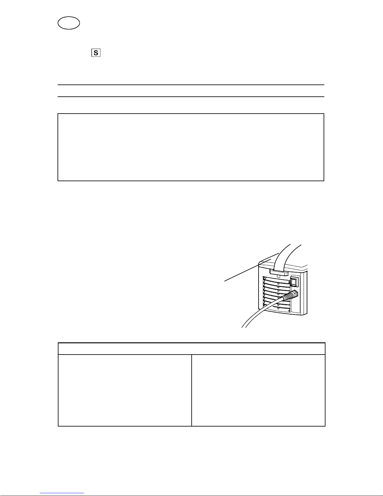
5.2 Mains power supply
Check that the welding power source is connected to
the correct voltage and that the correct fuse size is used.
A protective earth connection must be made in accordance
with regulations
Location of rating plate
5.2.1 Recommended fuse sizes and minimum cable area
Tradesarc 200
Mains voltage
230 V ¦10 %, 1--phase
Mains frequency 50--60 Hz
Mains cable, area 3G2.5 mm
2
Phase current I
1eff
14 A
Welding cable, area 16 mm
2
Fuse
anti--surge
type C MCB
16 A
16 A
NOTE!
The cable area and fuse rating above comply with Swedish regulations. Use the
welding power source in accordance with the relevant national regulations.
GB
-- 7 --
bh37d1em
6 OPERATION
6.1 PFC -- Power factor correction
The Tradesarc 200 is 230 V single--phase power sources equipped with a PFC circuit making it possible to use the full range of the machine on a 16 A fuse. The PFC
also protects the machines against fluctuating mains voltage and makes it safer to
use with a generator. Tradesarc 200 can operate with extra long mains cables, over
100 m, giving you a very larger working radius.
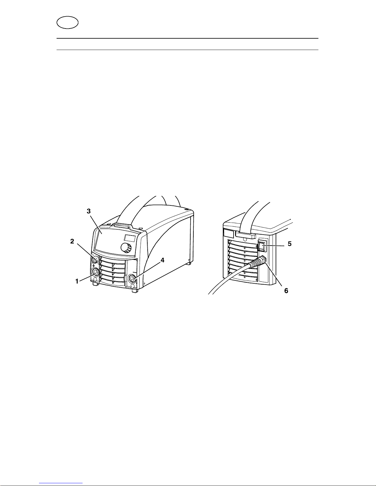
6.2 Connections and control devices
1 Connection (+)
MMA: for return cable or welding cable
TIG: for return cable
4 Connection (--)
MMA: for return cable or welding cable
TIG: for Tig torch l
2 Connection for remote control unit 5 Toggle switch for mains power supply 0 / 1
3 Control panel, see under 3.2 6 Mains cable
6.3 Connection of welding and return cable
The power source has two outputs, a positive terminal (+) and a negative terminal
(--), for connecting welding and return cables. The output to which the welding cable
is connected depends on the type of electrode used. The connecting polarity is
stated on the electrode packaging. Connect the welding cable to the terminal stated
on the electrode packaging.
Connect the return cable to the other output on the power source. Secure the return
cable’s contact clamp to the work piece and ensure that there is good contact
between the work piece and the output for the return cable on the power source.
6.4 Overheating protection
The welding power source has a thermal overload trip which operates if the
temperature becomes too high, interrupting the welding current and lighting a yellow
indicating lamp on the front of the power source. The thermal overload trip resets
automatically when the temperature has fallen.
GB
cmha2p11
cmha2p10
-- 8 --
bh37d1em
6.5 MMA welding
Tradesarc 200 gives direct current, and you can weld most metals to alloy and non--
alloy steel, stainless steel and cast iron.
Tradesarc 200 allows you to weld most coated electrodes from Ø 1.6 to Ø 3.25.
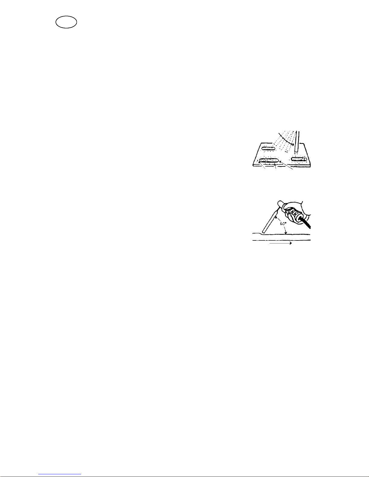
MMA weldingmay also be referred to as welding with coated electrodes. Striking the arc
melts the electrode, and its coating forms protective slag.
If, when striking the arc, the tip of the electrode is pressed against the metal, it immediately melts and sticks to the metal, rendering continued welding impossible.
Therefore, the arc has to be struck in the same way that you would light a match.
Quickly strike the electrode against the metal, then raise it so
as to give an appropriate arc length (approx. 2 mm). If the arc
is too long, it will crackle and spit before finally going out completely.
If you are working on a welding bench, check before attempting
to strike the arc that residual waste metal, pieces of electrode
or other objects on the bench do not insulate the part to be
welded.
Once the arc has been struck, move the electrode from left to
right. The electrode must be at an angle of 60˚ to the metal in
relation to the direction of welding.
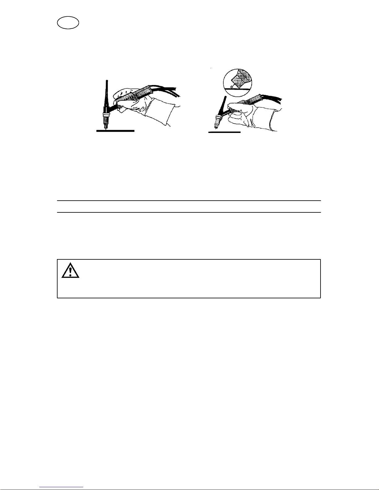
When you want to weld wide beads, or when you want the weld
to be so thick that you have to weld in a number of layers, however, you have to use lateral movements.
6.6 TIG welding
TIG welding melts the metal of the workpiece, using an arc struck from a tungsten
electrode, which does not itself melt. T he weld pool and the electrode are protected
by shielding gas.
TIG welding is particularly useful where high quality is demanded and for welding
thin plate. Tradesarc 200 also has good characteristics for TIG welding.
In order to TIG weld Tradesarc 200 must be equipped with:
S a TIG torch with gas valve
S a welding gas cylinder (a suitable welding gas)
S a welding gas regulator (suitable gas regulator)
S tungsten electrode
S suitable auxiliary material, if necessary.
GB
-- 9 --
bh37d1em
”Live TIG--start”
With “Live TIG start” the arc strikes when the tungsten electrode is brought into
contact with the workpiece and then lifted away from it.
6.7 Remote control unit
The remote control unit is connected to the remote control socket on the power
source.
7 MAINTENANCE
Regular maintenance is important for safe, reliable operation.
Only those persons who have appropriate electrical knowledge (authorized
personnel) may remove the safety plates to connect or carry out service,
maintenance or repair work on welding equipment.
CAUTION!
All guarantee undertakings from the supplier cease to apply if the customer himself
attempts any work in the product during the guarantee period in order to rectify any faults.
7.1 Inspection and cleaning
Power source
Check regularly that the welding power source is not clogged with dirt.
How often and which cleaning methods apply depend on: the welding process, arc
times, placement, and the surrounding environment. It is normally sufficient to blow
down the power source with dry compressed air (reduced pressure) once a year.
Clogged or blocked air inlets and outlets otherwise result in overheating.
TIG torch
The TIG torch’s wear parts should be cleaned and replaced at regular intervals in
order to achieve trouble--free welding.
GB
 Loading...