

Murdock M-PM14 Maintance Manual
P E T F O U N T A I N
I N S T A L L AT IO N / M A I N T E N A NC E I N S T R U C T I O N S
INSTALLATION INSTRUCTIONS FOR M-PM14 PET FOUNTAIN
Important: Read all instructions and refer to local
codes prior to installation.
l Local soil conditions may require more gravel for
drainage.
l It is recommended to include a supply stop
appropriate located on the supply line.
l An in-line PRV installed on the supply line is
recommended to ensure a working water pressure
of 40-60 psi
l A water filter should be installed on the supply line if
sediment or mineral content is a problem.
l Supply line must be flushed of all foreign materials
such as pipe dope, chips, etc.
l Piping and valve must be drained prior to being
subjected to freezing temperatures.
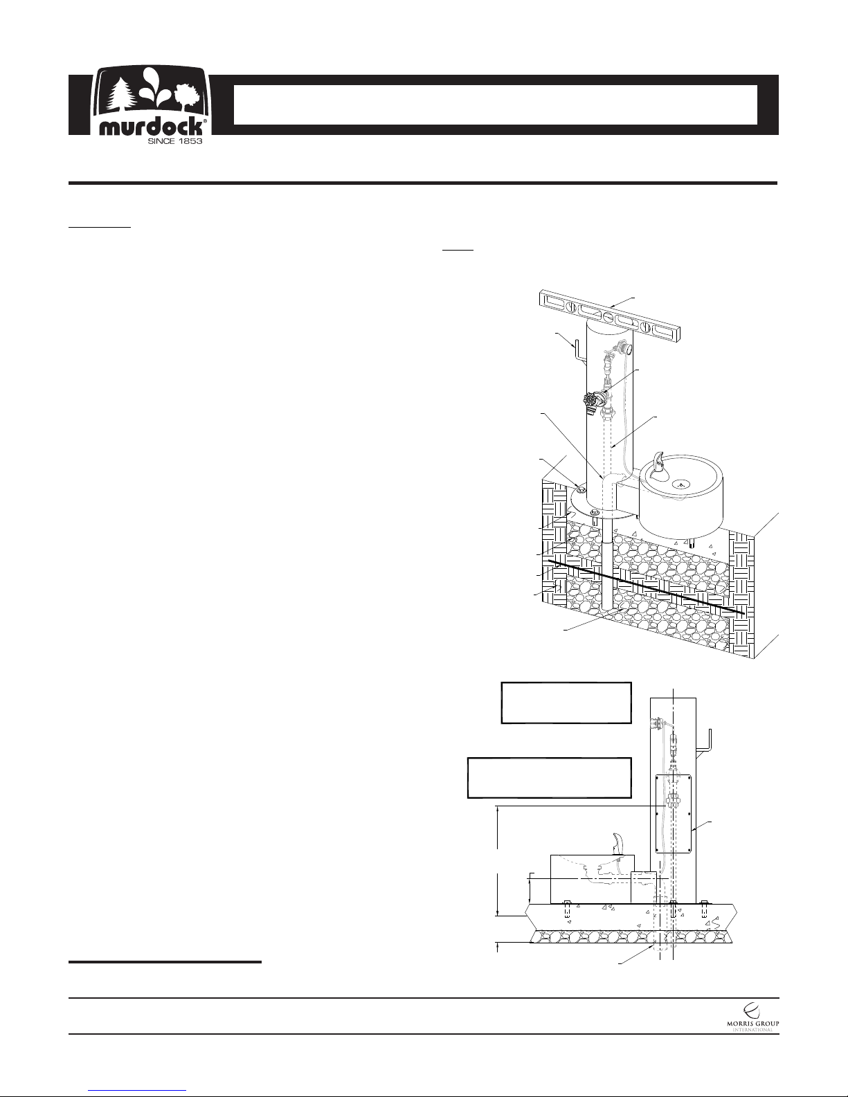
Prepare trench for water supply lines and waste line (if
required). At fountain location prepare hole to trench
depth and large enough for a person to work in. Lay
supply and waste into trench and above ground
allowing extra line to be trimmed during hook up, refer
to details for roughs.
Depending on code and design requirements, drain
may be open, French or sanitary connection. For
French drain, place a minimum of three cubic feet of
gravel under drain opening. Local soil conditions may
require more gravel drainage.
Refill trench and hole, compacting back fill as required.
Leave sufficient depth in hole to accommodate
concrete pour, 4” minimum recommended.
Prepare slab area surrounding fountain spreading and
compacting gravel as necessary. Prepare form
approximately 6” diameter to protect supply and waste
stub outs. Protect exposed valve assembly, tubing and
tube openings to prevent damage to equipment or to
prevent tubes from becoming filled with soil or debris.
Then pour concrete, ensure concrete is flat and level.
NOTE: FRENCH DRAIN SHOWN.
CONSULT LOCAL CODE
REQUIREMENTS.
HOSE HANGER
WASTE CONNECTION
FOR Ø1-1/4" OD CLOSE
ELBOW, BY OTHERS
1/2"-13 UNC MTG
HARDWARE,
PROVIDED
POURED
CONCRETE
GRAVEL
FROST LINE
EARTH
MINIMUM 3 CUBIC
FEET OF POROUS
GRAVEL FILL
FOR FREEZE RESISTANT
OPTION REFER TO -FRU
MANUAL #9938-340-0M1
VALVE SPECIFICATIONS:
MINIMUM/MAXIMUM PRESSURE:
30/100 PSI
LEVEL
HOSE BIBB w/ VACCUUM
BREAKER
SUPPLY INLET CONNECTION
FOR 3/4" NPTM, BY OTHERS
ACCESS PANEL
Please visit www.murdockmfg.com
for most current specifications.
MURDOCK MFG. • 15125 Proctor Avenue • City of Industry, CA 91746 USA
Phone 800-453-7465 or 626-333-2543 • Fax 626-855-4860 • www.murdockmfg.com
7020-204-001
Page 1 of 3
M-PM14
17"
REF
4" REC
MIN
4"
2" PVC DWV DRAIN
PIPE RECOMMENDED,
BY OTHERS
Member of
Revised: 05/11/17
P E T F O U N T A I N
I N S T A L L AT IO N / M A I N T E N A NC E I N S T R U C T I O N S
INSTALLATION INSTRUCTIONS FOR M-PM14 PET FOUNTAIN
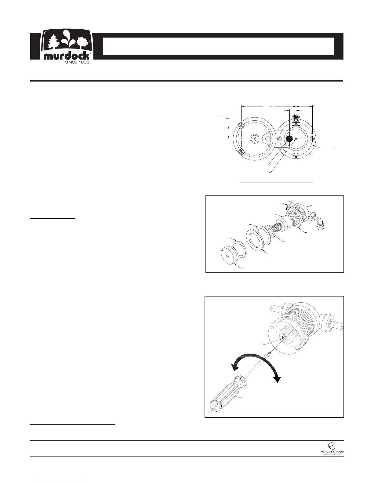
Once concrete has cured, drill 3/4” diameter by 2” deep
holes following the pattern shown in the mounting base
detail for the provided drop-in anchors. Using the anchor
setting tool, hammer the provided drop-in anchors into the
drilled holes. Align mounting points on the fountain to the
mounting anchors in the concrete and secure the fixture to
the slab using the provided mounting hardware.
Through access panel make up connections to fountain’s
3/8” OD (1/4” nominal) plain end supply inlet and 1-1/4” OD
close elbow waste outlet.
To ensure plumb installation, lay a bubble level on fountain
bowl and adjust using shims or washers until the unit is level.
To test operation of bubbler, depress the activation
pushbutton and adjust flow rate as required and check all
connections for leaks.
MAINTENANCE
All normal maintenance is done from above the ground.
v Always shut off wate r supply w hen doing any
maintenance.
v To remove pedestal mounted pushbutton assembly
remove access panel. From inside of the pedestal,
remove inlet and outlet lines from push-in ports of the
valve body. Using a spanner wrench remove pushbutton
and retaining ring.
v To replace regulator, use a spanner wrench to remove
pushbutton and retaining ring from the flange collar. Use a
spanner wrench to remove retainer from the inside of the
flange collar. Remove regulator, insert new regulator and
align ports to new regulator with mating ports of valve
body then replace retaining ring.
v Re-assemble in reverse order. When replacing inlet and
outlet line ensure to insert supply line into valve port
labeled “IN”. Ensure that plastic line is not kinked when
fountain is re-assembled.
7
3
"
8
TYP
WASTE OUTLET
Retaining
Ring
3
16
"
8
2"
SUPPLY INLET
MOUNTING BASE DETAIL
1/4" Push-In
Elbows
Regulator
Fiber Ring
Rubber Gasket
Pushbutton
Ø3/16"
HOLE
Retainer
5"
TYP
Ø9
Valve Body w/
Flange Collar
Brass Nut
7
"
8
Please visit www.murdockmfg.com
for most current specifications.
MURDOCK MFG. • 15125 Proctor Avenue • City of Industry, CA 91746 USA
Phone 800-453-7465 or 626-333-2543 • Fax 626-855-4860 • www.murdockmfg.com
7020-204-001
Page 2 of 3
M-PM14
DECREASE
FLOW
INCREASE
FLOW
SLOTTED
SCREWDRIVER
FLOW ADJUSTMENT
The water flow can be adjusted using a slotted
narrow blade screwdriver and turning clockwise to
increase flow and counterclockwise to decrease flow.
Member of
Revised: 05/11/17
 Loading...