

CONTEMPORARY WATER COOLERS
OUTDOOR BOTTLE FILLERS
I N S TA L L AT I O N / M A I N T E N A N C E I N S T R U C T I O N S
I N S TA L L AT I O N / M A I N T E N A N C E I N S T R U C T I O N S
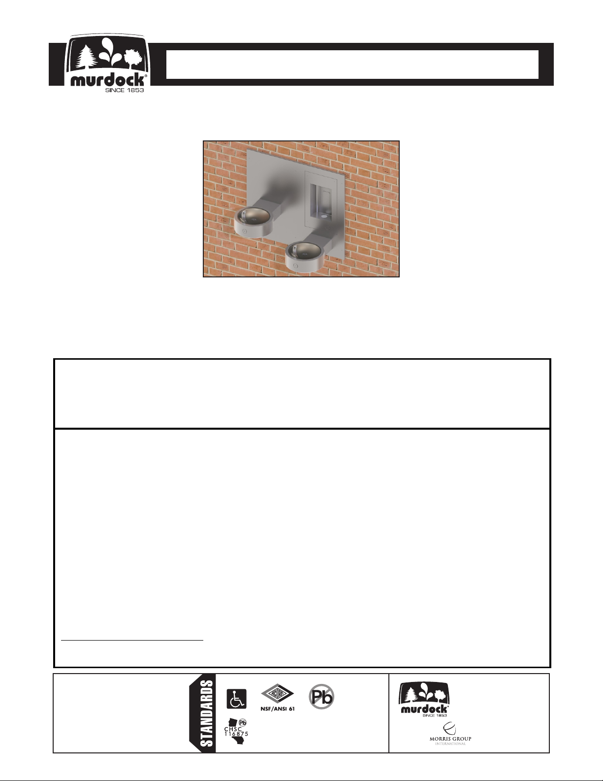
M-OBR4-GRD Series
RECESSED OUTDOOR BOTTLE FILLER WITH
BI-LEVEL DRINKING FOUNTAIN
TECHNICAL ASSISTANCE TOLL FREE TELEPHONE NUMBER:
1.800.591.9360
Technical Assistance Fax: 1.626.855.4894
NOTES TO INSTALLER:
1. Please leave this documentation with the owner of the fixture when finished.
2. Please read this entire booklet before beginning the installation.
3. Check your installation for compliance with plumbing, electrical and other applicable codes.
LIMITED WARRANTY - UNITED STATES & CANADA
Murdock warrants that its products are free from defects in material or workmanship under normal use and
service for a period of one year from date of install or for 18 months after the date of shipment from the factory,
whichever comes first. The sealed refrigeration system is warranted for five years. Murdock’s liability under this
warranty shall be discharged solely by replacement or repair of defective material, provided Murdock is notified in
writing within one year from date of shipment, F.O.B. Industry, California.
This warranty does not cover installation or labor charges and does not apply to materials, which have been
damaged by other causes such as mishandling, improper care or abnormal use. The repair or replacement of the
defective materials shall constitute the sole remedy of the Buyer and the sole remedy of Murdock under this
warranty. Murdock shall not be liable under any circumstances for incidental, consequential or direct charges
caused by defects in the materials, or any delay in the repair or replacement thereof. This warranty is in lieu of all
other warranties expressed or implied. Product maintenance instructions are issued with each unit and disregard
or non-compliance with these instructions will constitute an abnormal use condition and void the warranty.
Stainless steel must be protected on job site during construction and must be properly maintained after the water
has been introduced into the water cooler or drinking fountain, or Murdock’s limited warranty is void.
LIMITED EXPORT WARRANTY - One year on parts only.
Murdock assumes no responsibility for use of void or
suspended data. © Copyright Murdock, City of
Industry, CA Member of Morris Group International.
Please visit www.murdockmfg.com for most
current specifications.
7020-960-001 Date: 12/01/17
COMPLIES WITH
Test rating conditions are
compliant with ARI 1010.
Federal
Public Law
111-380
(No Lead)
Member of
MURDOCK
15125 Proctor Ave.
City of Industry, CA
91746 U.S.A.
Phone 800-591-9360
626-336-4561
Fax 626-855-4894
www.murdockmfg.com
CONTEMPORARY WATER COOLERS
OUTDOOR BOTTLE FILLERS
I N S TA L L AT I O N / M A I N T E N A N C E I N S T R U C T I O N S
I N S TA L L AT I O N / M A I N T E N A N C E I N S T R U C T I O N S
IMPORTANT
This fixture is intended to dispense water that has been lowered in temperature, but otherwise remains
unchanged by the materials in the drinking fountain.
NOTICE
A dielectric coupling must be used to connect the drinking fountain to the water supply. A nonmetallic coupler is
furnished with this water cooler to meet this requirement.
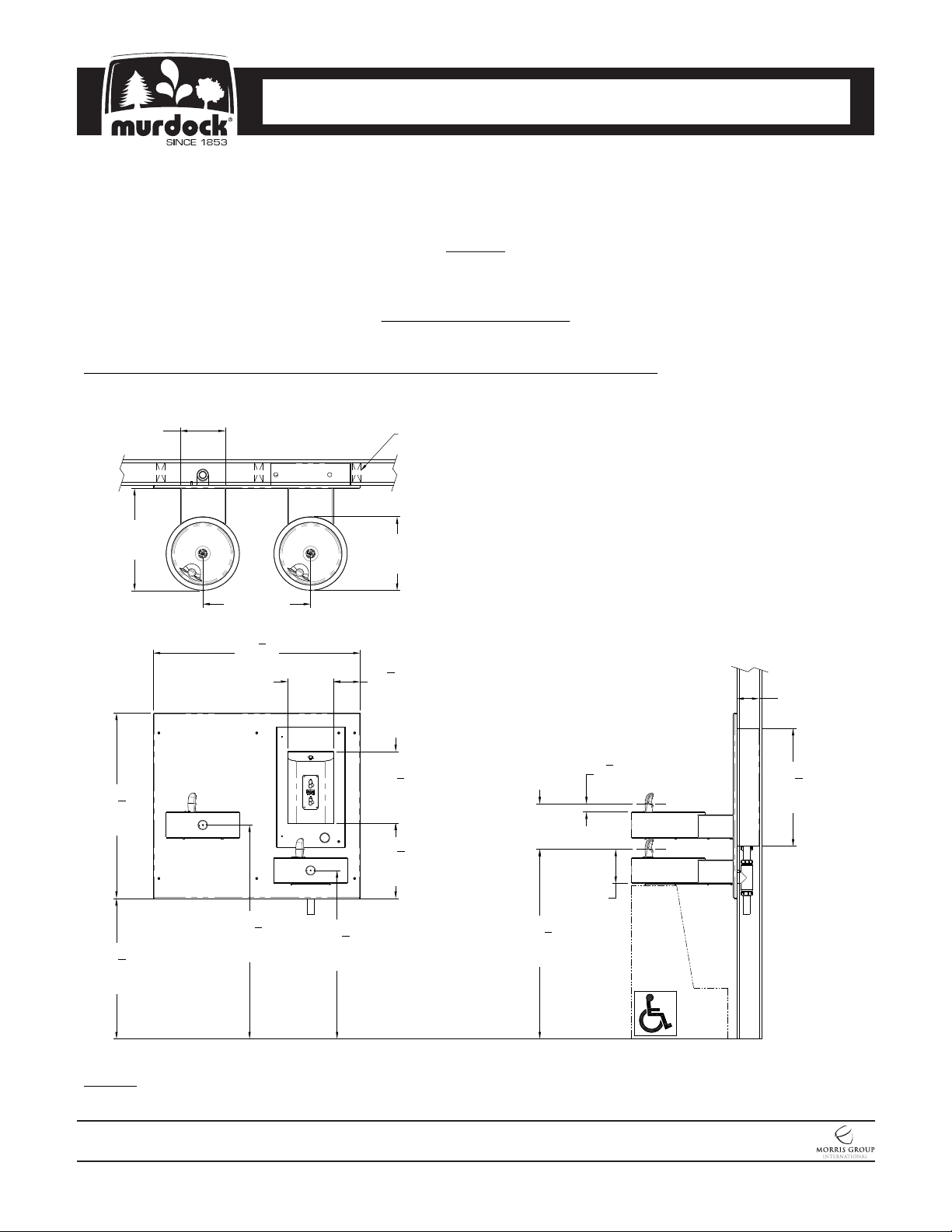
DIMENSIONAL DRAWING
Prior to roughing in, consult with local, state, and federal codes for proper mounting height.
M-OBR4-GRD Recessed Outdoor Bottle Filler with Bi-Level Drinking Fountain
18"
[457]
5
32
8
[829]
3
24
4
[629]
8"
[203]
"
"
19" [483]
1
36
"
2
[927]
5
*37
"
8
[956]
8"
[203]
*29
[752]
SHOWN WITH
2x4 STUD WALL
General Notes:
13"
[330]
3
4
"
4
[121]
5
12
8
[320]
"
1. All dimensions are in inches [mm]
*2. Dimensions shown are for recommended adult height.
Adjust vertical dimensions as necessary to comply with
federal, state & local codes
3. Stop valve not provided
4"
[102]
3
1
8
[35]
"
20
3
"
4
[527]
8"
[203]
13
1
"
4
[337]
6"
[152]
5
"
8
3
*33
8
[848]
"
NOTES: Dimensions shown for Adult ADA compliant installation. For Child ADA compliant parallel approach installation,
decrease height of installation by 3 inches. Provide clear floor space as required. Adjust vertical dimensions as required to
comply with federal, state, and local codes.
MURDOCK MFG. • 15125 Proctor Avenue • City of Industry, CA 91746 USA
Phone 800-453-7465 or 626-333-2543 • Fax 626-855-4860 • www.murdockmfg.com
7020-960-001
Page 2 of 17
M-OBR4-GRD
Member of
New: 12/01/17
CONTEMPORARY WATER COOLERS
OUTDOOR BOTTLE FILLERS
I N S TA L L AT I O N / M A I N T E N A N C E I N S T R U C T I O N S
I N S TA L L AT I O N / M A I N T E N A N C E I N S T R U C T I O N S
IMPORTANT:
1. Water Supply Service Stop Valve, and Water Connections to be supplied by others in accordance with local
codes.
2. Waste is 1-1/4” Outer Diameter. Drinking Fountain water inlet is 1/4” outer diameter Push-In Fitting. Bottle
Filler water inlet is 1/4” Outer Diameter Push-In Fitting. Water line by others.
3. Completely flush supply lines of all foreign debris before connecting to fixture.
4. Do NOT solder tubes inserted into the chiller, bottle filler or the fountain strainer as damage to the o-rings on
the push-in fittings may result.
5. All burrs must be removed from outside of cut tubes before inserting into strainer or other components.
6. WARNING: Warranty is voided if installation is not made following current Murdock Mfg. installation
instructions and if components are assembled to the fixture that are not approved by Murdock Mfg.
7. Fixture operates within water pressure range of 25 PSIG (174 kPa) to 105 PSIG (724 kPa).
8. Per UPC 609.10-All building water supply systems in which quick acting valves are installed shall be
provided with devices to absorb the hammer caused by high pressure resulting from the quick closing of the
valve. These pressure-absorbing devices shall be approved mechanical devices. Water pressure-absorbing
devices shall be installed as close as possible to the quick closing valve
PRIOR TO INSTALLATION:
1. Read all installation instructions carefully, before proceeding.
2. Carefully remove all fixture components from packaging, preventing scratching or damage. Inspect fixture and
all parts from damages and all parts that are bolted on.
3. Provide mounting surface, adequate to support the fixture and loads on the fixture.
4. Provide rough-ins as shown on the roughing-in and dimensional drawing, including water supply, drain pipe
and gravel drain well. (See rough-in details)
5. Completely flush water supply lines of all foreign debris, before connecting to the fixture.
DRINKING FOUNTAIN START UP:
1. Before connecting power supply, but after thoroughly flushing the supply line and connecting it to the cooler,
turn on building water supply and check all connections for leaks.
2. Air within the drinking fountain system or the structure supply piping will cause an irregular bubbler outlet
stream until purged out by incoming water. Covering the bubbler with a clean cup (or similar object) is
recommended when first activating drinking fountain to prevent excessive splashing.
3. Depress front push pad until steady water stream is achieved.
4. If water flow requires adjustment, insert a slotted narrow blade screwdriver in the hole centered on the
underside of the fixture in the knee clearance area up to the flow regulator. Turning clockwise will increase
flow and turning counterclockwise will decrease flow.
5. Recheck all water connections with water flowing through system.
BOTTLE FILLER START UP:
1. Pushbutton Operated: Air within the bottle filler system or the structure supply piping will cause an irregular
spout outlet stream until purged out by incoming water. Press and hold pushbutton until steady water stream
is achieved
2. Sensor Operated: Hold container to be filled just below the sensor in the center of the filler spout and then
move the container upward and water flow will start automatically. When the container is almost filled, lower
the container below the sensor until the water stops flowing. (See label on the bottle filler.)
MURDOCK MFG. • 15125 Proctor Avenue • City of Industry, CA 91746 USA
Phone 800-453-7465 or 626-333-2543 • Fax 626-855-4860 • www.murdockmfg.com
7020-960-001
Page 3 of 17
M-OBR4-GRD
Member of
New: 12/01/17
CONTEMPORARY WATER COOLERS
OUTDOOR BOTTLE FILLERS
I N S TA L L AT I O N / M A I N T E N A N C E I N S T R U C T I O N S
I N S TA L L AT I O N / M A I N T E N A N C E I N S T R U C T I O N S
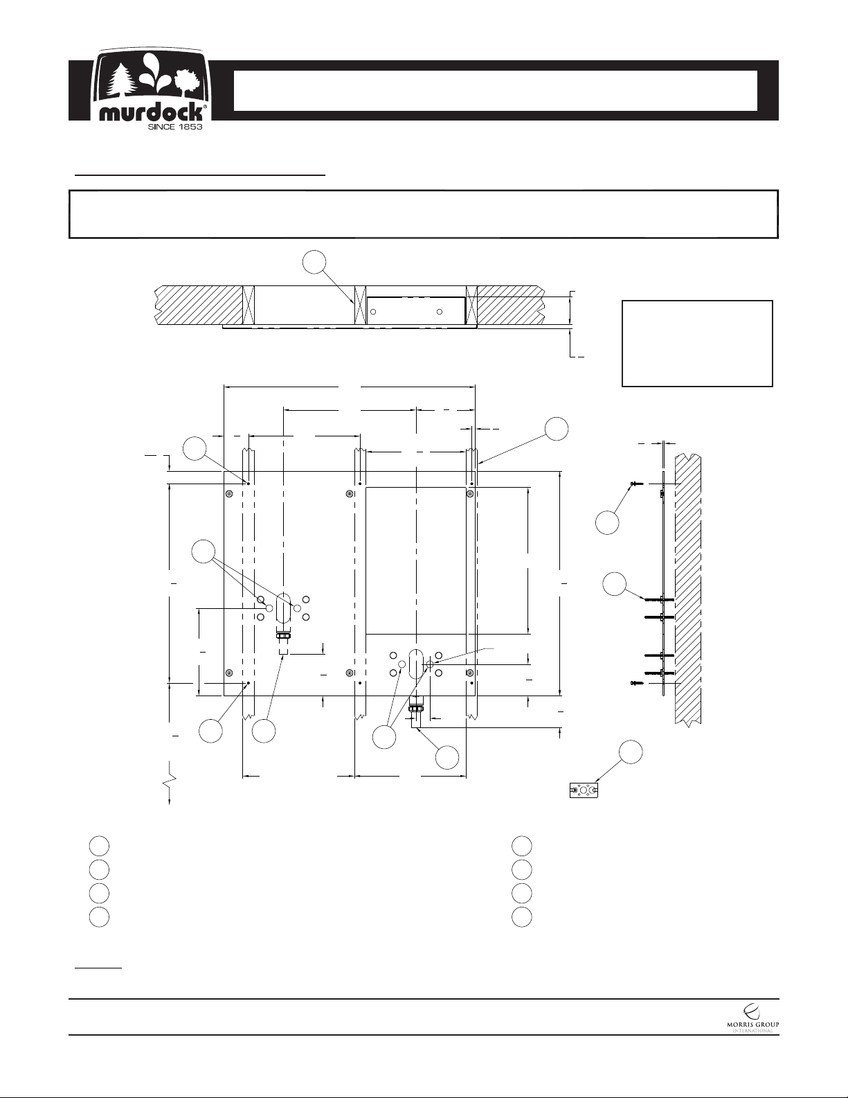
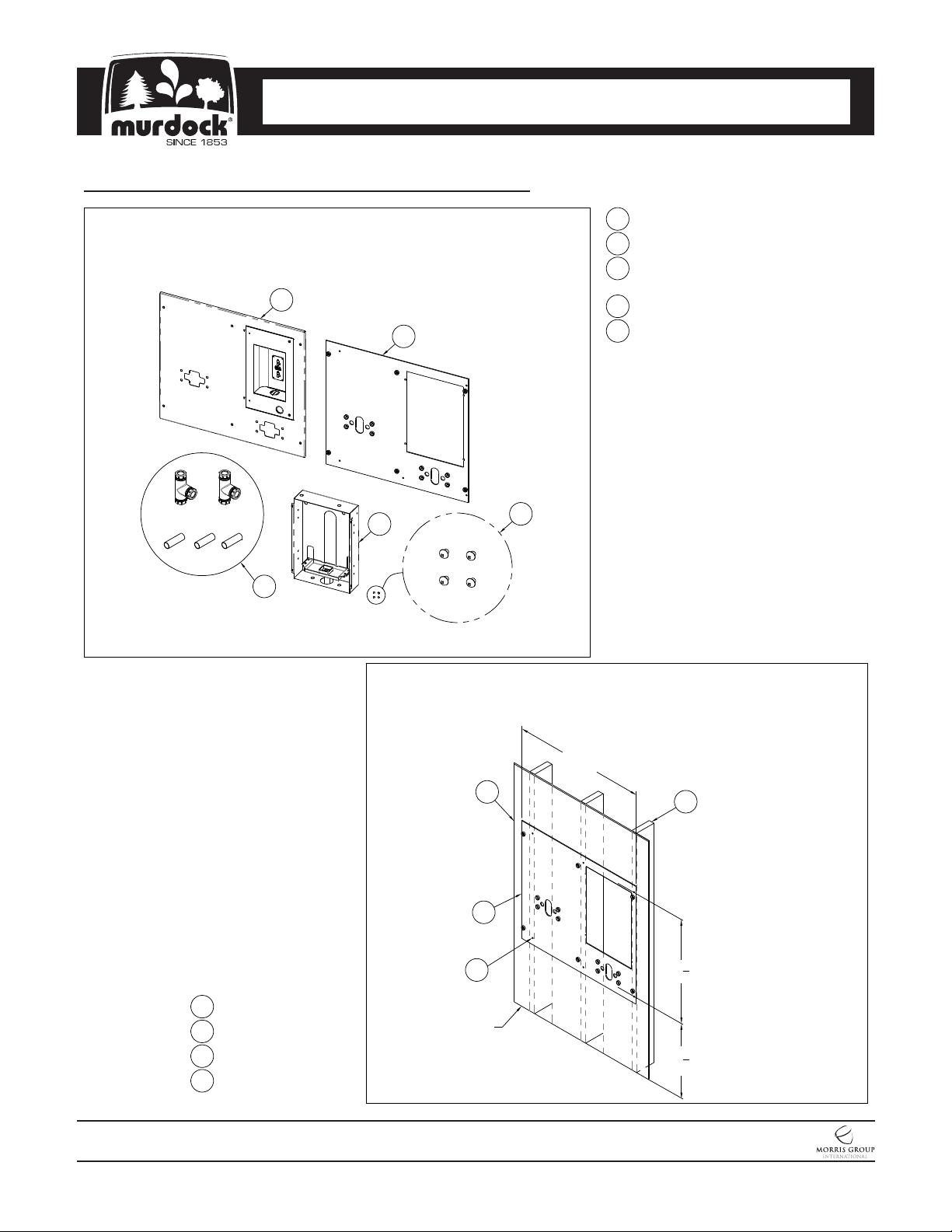
Mounting Installation
Provide wall opening as indicated in rough-in detail provided. Block-out for bottle filler box and provide structural support for
1
mounting plate ø1/4” anchoring holes provided.
7
4"
Note:
Electrical Service
Required for Plug-In
5
"
8
36"
14
1
"
2
3
"
8
1
"
2
7
19" 8
1
3
" 16"
13
1
16
4
"
2
Transformer; Transformer
does not sit inside Botle
Filler Box.
1
"
4
3
1
28
"
2
1
12
"
2
7
26
A.F.F.
1
1-1/4" O.D. Drinking Fountain Waste
2
1-1/4" O.D. Bottle Filler/Drinking Fountain Waste
3
1/4" O.D. Drinking Fountain Supply Inlet
4
Mounting Holes
4
"
8
1
Stud Frame
Wall Spacing
16"
7
5
8
5
21"
1
32
"
8
Ø1"
"
2"
3
2
16"
1
4
"
2
1
4
"
2
5
1/4" Anchoring Hardware, by others
6
5/16" Threaded Studs
7
2x6 Stud Wall, for reference only
8
GFCI Electrical Service Protected Circuit
for -SO Sensor Operated units, by others
6
8
NOTES: Dimensions shown for Adult ADA compliant installation. For Child ADA compliant parallel approach installation,
decrease height of installation by 3 inches. Provide clear floor space as required. Adjust vertical dimensions as required to
comply with federal, state, and local codes.
MURDOCK MFG. • 15125 Proctor Avenue • City of Industry, CA 91746 USA
Phone 800-453-7465 or 626-333-2543 • Fax 626-855-4860 • www.murdockmfg.com
7020-960-001
Page 4 of 17
M-OBR4-GRD
Member of
New: 12/01/17
CONTEMPORARY WATER COOLERS
OUTDOOR BOTTLE FILLERS
I N S TA L L AT I O N / M A I N T E N A N C E I N S T R U C T I O N S
I N S TA L L AT I O N / M A I N T E N A N C E I N S T R U C T I O N S
Mounting Installation (Continued)
Separate Fixture Panel, Bottle Filler Box, Mounting Plate and #10-32 x 1/4"
2
Screws from packaging careful to avoid damage to fixtures and fixture
sub-assemblies.
1
2
Bottle Filler Panel
1
Mounting Plate
2
Waste Outlet, Ref. only
3
(Plumbing may vary)
Bottle Filler Box
4
(4) #10-32 x 1/4" Phillps
5
Head Screws
4
3
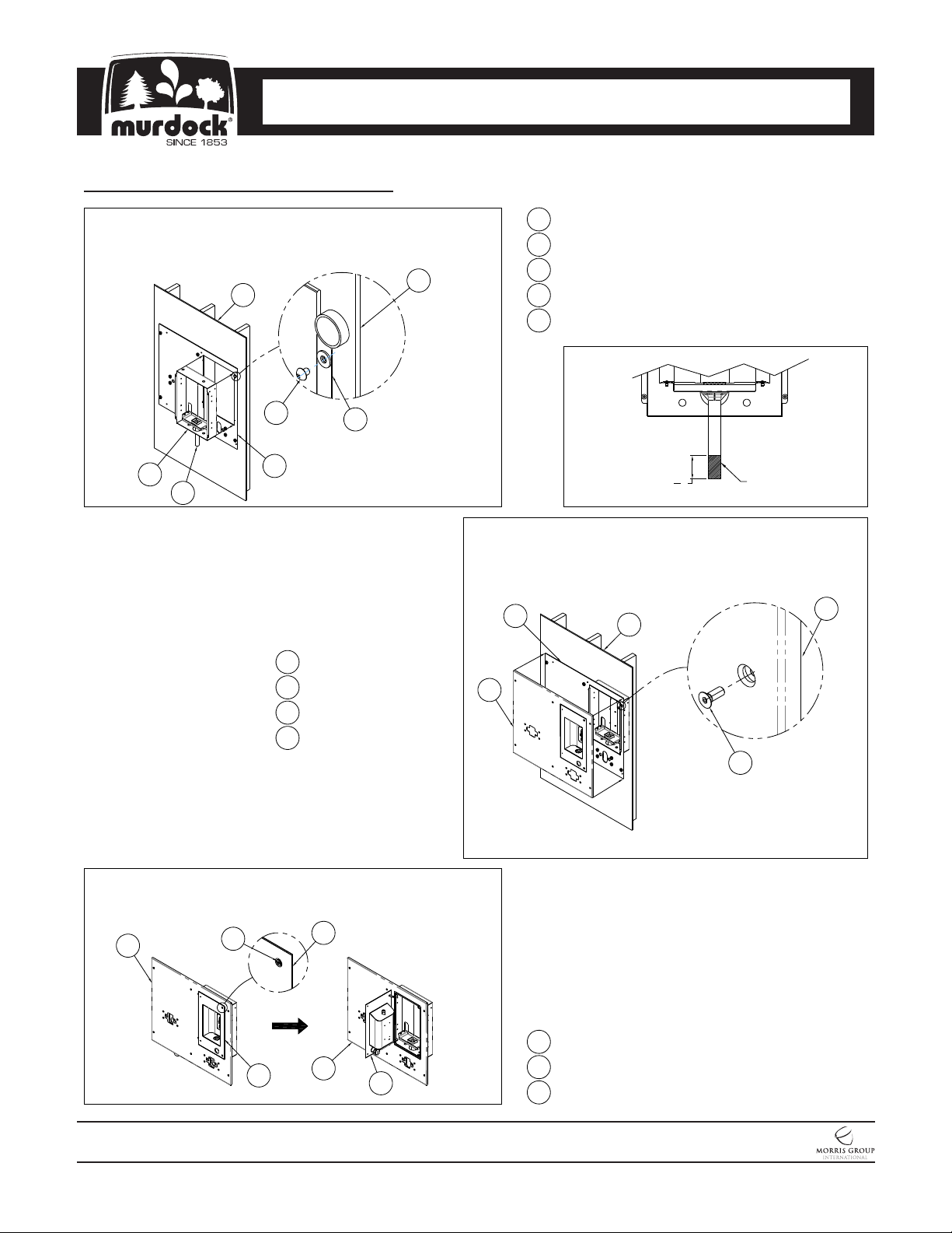
Supporting Mounting Plate against wall, align Bottle Filler opening and
3
Mounting Plate Ø1/4" Anchoring holes with structural support before fixing to
wall with installer provided Anchoring Hardware.
5
36"
3
1
2
4
Mounting Plate
1
2x6 Stud Frame
2
Finish Wall, Ref. only
3
Anchoring Hardware,
4
provided by others
Finished
Floor
MURDOCK MFG. • 15125 Proctor Avenue • City of Industry, CA 91746 USA
Phone 800-453-7465 or 626-333-2543 • Fax 626-855-4860 • www.murdockmfg.com
7020-960-001
Page 5 of 17
M-OBR4-GRD
28
26
1
"
2
7
"
8
Member of
New: 12/01/17
CONTEMPORARY WATER COOLERS
OUTDOOR BOTTLE FILLERS
I N S TA L L AT I O N / M A I N T E N A N C E I N S T R U C T I O N S
I N S TA L L AT I O N / M A I N T E N A N C E I N S T R U C T I O N S
Bottle Filler Installation
Position Bottle Filler Box in the center of the Mounting Plate
1
opening and secure with #10-32 x 1/4" Phillips Head Screws.
Note: Cutoff 2-1/2" of material from the tailpiece. See Detail A.
1
4
3
5
2
1
2
3
4
3
Finished Wall
Mounting Plate
Bottle Filler Panel
10-32 x 1/2" Screws
2
Finished Wall1
Mounting Plate2
Bottle Filler Box3
4
10-32 x 1/4" Screws
5
1-1/4" OD Tailpiece
Detail A
1
2
"
2
Position Bottle Filler Panel and center to Mounting Plate and
2
secure with #10-32 x 1/2" Stainless Steel Flat Head Center
Reject Hex Screw.
2
3
1
Cutoff Material
4
3
With Bottle Filler Panel installed, to open Bottle Filler, remove
3
#10-32 x 3/4" Flat Head Center Reject Screws and swing open
Bottle Filler.
1
3
2
2
1
Bottle Filler Panel
2
1
2
Bottle Filler
3
#10-32 x 3/4" Screws
MURDOCK MFG. • 15125 Proctor Avenue • City of Industry, CA 91746 USA
Phone 800-453-7465 or 626-333-2543 • Fax 626-855-4860 • www.murdockmfg.com
7020-960-001
Page 6 of 17
M-OBR4-GRD
Member of
New: 12/01/17

CONTEMPORARY WATER COOLERS
OUTDOOR BOTTLE FILLERS
I N S TA L L AT I O N / M A I N T E N A N C E I N S T R U C T I O N S
I N S TA L L AT I O N / M A I N T E N A N C E I N S T R U C T I O N S
Drinking Fountain Installation
Install the drinking fountain threaded studs through the Bottle
1
Filler Panel and into the Mounting Plate so that a minimum of
1-1/4" of thread projects beyond Bottle Filler Panel .
1
3
1
Finished Wall
2
Bottle Filler Panel
3
5/16"-18 Threaded Studs
2
2
1
Drinking Fountain
2
Bottom Access Panel
#10-32 x 3/8" Screws3
Align threaded studs with drinking fountain mounting
3
openings and slide fixtures to panel and secure with nuts
and washers.
1
3
Remove the Drinking Fountain bottom Access Panel by
2
removing the Access Panel Vandal Resistant Screws. Be sure
to safeguard drain Access Panel screws.
1
2
3
5
3
2
3
1
Finished Wall
2
5/16"-18 Threaded Studs
3
Drinking Fountain Housing
4
5/16"-18 Hex Nut4
5/16"-18 Zinc Plated Washer5
MURDOCK MFG. • 15125 Proctor Avenue • City of Industry, CA 91746 USA
Phone 800-453-7465 or 626-333-2543 • Fax 626-855-4860 • www.murdockmfg.com
7020-960-001
Page 7 of 17
M-OBR4-GRD
Member of
New: 12/01/17

CONTEMPORARY WATER COOLERS
OUTDOOR BOTTLE FILLERS
I N S TA L L AT I O N / M A I N T E N A N C E I N S T R U C T I O N S
I N S TA L L AT I O N / M A I N T E N A N C E I N S T R U C T I O N S
Supply Connections
It is recommended that a supply stop be installed before making up
1
connections to the fixture 3/8” OD supply inlet.
1
3/8" OD Water Supply Line
2
Shut-Off Valve
3
Fixture Supply Inlet
1
2
3
To Building Water
Supply Line
Multiple Water Supply connections are required from the Building
2
Water Supply Line to connect to (2) 1/4" NCT x 1/4" OD Push-In
Y-Strainers and 1/4" NPT Male Fitting for the Bottle Filler Supply
Line (See Steps 3 and 4). DO NOT SOLDER. Soldering will
damage strainer O-Ring preventing a watertight seal. Layout
shown for reference only.
4
1
3/8" OD Shut-Off Valve (Ref. Only)
2
3/8" OD Water Supply Tubing (Ref. Only)
3
3/8" OD Push-in Tee (Ref. Only)
4
3/8" OD Push-in Elbow (Ref. Only)
5
3/8" OD Push-in x 1/4" Female NPT (Ref. Only)
6
1/4" NCT x 1/4" OD Push-In Y-Strainer
7
1/4" OD x 1/4" NPT Male Fitting
8
1/4" OD Water Supply Tubing to
Drinking Fountain
9
1/4" OD Water Supply Tubing to Bottle Filler
6
2
8
9
5
7
8
MURDOCK MFG. • 15125 Proctor Avenue • City of Industry, CA 91746 USA
Phone 800-453-7465 or 626-333-2543 • Fax 626-855-4860 • www.murdockmfg.com
7020-960-001
Page 8 of 17
M-OBR4-GRD
To Building Water
3
2
6
Supply Line
2
1
3
2
Member of
New: 12/01/17

CONTEMPORARY WATER COOLERS
OUTDOOR BOTTLE FILLERS
I N S TA L L AT I O N / M A I N T E N A N C E I N S T R U C T I O N S
I N S TA L L AT I O N / M A I N T E N A N C E I N S T R U C T I O N S
Supply Connections (Continued)
Connect two of the Multiple Water Supply Connections to the 1/4" NCT x 1/4" OD
3
Push-In Y-Strainer located within the Drinking Fountains. To increase or decrease
flow, use slotted screwdriver. Re-install Access Panel with screws.
1/4" NCT x 1/4" OD
1
Push-In Y-Strainer
Drinking Fountain
2
Drinking Fountain Bubbler3
3
2
3
Ø
" Hole
16
1
6
Decrease
4
5
Flow
Connect the last Multiple Water Supply Connection to the 1/4" OD Tube x 1/4"
4
NPT Male Fitting. (Note: An adapter is required to connect the Main Water
Supply Line to the 1/4" Male NPT Fitting). Connect the blue 1/4" OD Tube to
Bottle Filler Spout.
Increase
Flow
Slotted
Screwdriver
4
Pushbutton4
Bottom Access Panel5
Access Panel Scews6
4
3
1
Water Supply Tubing
2
3/8" OD x 1/4" Female NPT Adapter
(For Reference Only)
3
1/4" OD x 1/4" NPT Male Fitting
4
Bottle Filler Spout
5
1/4" OD Blue Tube
2
1
MURDOCK MFG. • 15125 Proctor Avenue • City of Industry, CA 91746 USA
Phone 800-453-7465 or 626-333-2543 • Fax 626-855-4860 • www.murdockmfg.com
7020-960-001
Page 9 of 17
M-OBR4-GRD
5
Member of
New: 12/01/17

CONTEMPORARY WATER COOLERS
OUTDOOR BOTTLE FILLERS
I N S TA L L AT I O N / M A I N T E N A N C E I N S T R U C T I O N S
I N S TA L L AT I O N / M A I N T E N A N C E I N S T R U C T I O N S
Waste Plumbing Installation
Remove the 1-1/4" Tee Assemblies with compressions and the 1-1/4" OD x 4" Long
1
Brass Tubing from packaging.
1
2
1
1-1/4" Tee Assembly with 1
Slip Joint Compression Nuts
1-1/4" OD x 4" Long2
Brass Tubing
From the interior of the building, install Tee Assembly with Compression to
2
Drinking Fountain and Bottle Filler. Cut to fit Drinking Fountain tailpiece.
1
1-1/4" OD Bottle Filler Tailpiece
2
1-1/4" Tee Assembly with
Slip Joints Compression Nuts
3
1-1/4" OD Drinking Fountain
Tailpiece
4
1-1/4" OD Waste Outlet Tailpiece
5
Bottle Filler
1
2
1
2
"
4
4
2
4
5
MURDOCK MFG. • 15125 Proctor Avenue • City of Industry, CA 91746 USA
Phone 800-453-7465 or 626-333-2543 • Fax 626-855-4860 • www.murdockmfg.com
7020-960-001
Page 10 of 17
M-OBR4-GRD
1
3
Member of
New: 12/01/17

CONTEMPORARY WATER COOLERS
OUTDOOR BOTTLE FILLERS
I N S TA L L AT I O N / M A I N T E N A N C E I N S T R U C T I O N S
I N S TA L L AT I O N / M A I N T E N A N C E I N S T R U C T I O N S
Waste Plumbing Installation (Continued)
From the interior of the building of the fixture wall, install Tee Assembly with
3
Compression to Drinking Fountain with Two tailpieces. Cut to fit Drinking
Fountain tailpiece.
1
2
1
1-1/4" OD Vent Outlet Tailpiece
2 1-1/4" Tee Assembly with Slip
Joint Compression Nuts
1-1/4" OD Drinking Fountain3
Tailpiece
1-1/4" OD Waste Outlet Tailpiece4
1
2
"
4
4
1
2
4
Install P-Traps to Waste outlets. P-Traps are provided by others.
4
3
3
2
1
1
P-Trap, by others
2 1-1/4" OD Waste Outlet Tailpiece
3
Bottle Filler
1
MURDOCK MFG. • 15125 Proctor Avenue • City of Industry, CA 91746 USA
Phone 800-453-7465 or 626-333-2543 • Fax 626-855-4860 • www.murdockmfg.com
7020-960-001
Page 11 of 17
M-OBR4-GRD
2
1
Member of
New: 12/01/17

CONTEMPORARY WATER COOLERS
OUTDOOR BOTTLE FILLERS
I N S TA L L AT I O N / M A I N T E N A N C E I N S T R U C T I O N S
I N S TA L L AT I O N / M A I N T E N A N C E I N S T R U C T I O N S
Water Filter Cartridge Replacement Instructions:
1. Open Bottle Filler Access Door by unfastening #10-32
screws from Bottle Filler Access Door .
2. Locate Shut-Off Valve Knob and give it a 1/4 turn
clockwise to shut-off water supply.
3. With the Filter Assembly secured on the unit, hold the
Cap firmly, turn the Replaceable Cartridge Filter
counterclockwise to remove.
3. Remove and replace the cartridge turning clockwise to
secure.
4. Turn Shut-Off Valve Knob a 1/4 turn counterclockwise
to open water supply.
5. Test for leaks and proper operation before closing
Bottle Filler Access Door and re-fastening #10-32
Screws.
Bottle Filler
Access Door
#10-32 Screws
Water Inlet
Valve Open
Water Inlet
Valve Closed
Replacement
Cartridge
MURDOCK MFG. • 15125 Proctor Avenue • City of Industry, CA 91746 USA
Phone 800-453-7465 or 626-333-2543 • Fax 626-855-4860 • www.murdockmfg.com
7020-960-001
Page 12 of 17
M-OBR4-GRD
Member of
New: 12/01/17

CONTEMPORARY WATER COOLERS
OUTDOOR BOTTLE FILLERS
I N S TA L L AT I O N / M A I N T E N A N C E I N S T R U C T I O N S
I N S TA L L AT I O N / M A I N T E N A N C E I N S T R U C T I O N S
Trouble Shooting:
IMPORTANT: BEFORE MAKING ANY OF THE REPAIRS LISTED, MAKE SURE THE
WATER CHILLER IS DISCONNECTED FROM THE ELECTRICAL SUPPLY AND THE
WATER SUPPLY VALVE IS SHUT OFF.
TROUBLE SHOOTING:
1. ADJUSTMENTS:
a. Cartridge – The water flow can be adjusted using a slotted narrow blade screwdriver and turning
clockwise to increase flow and counterclockwise to decrease flow.
b. Cold Water Thermostat – The water temperature can be adjusted using a slotted screwdriver and turning
clockwise to make colder and counterclockwise to make warmer.
c. Bubbler Stream - Bubbler can be rotated slightly to direct the stream backwards or forwards. Adjust the
stream to minimize splashing. Splashing may occur from bubbler stream if the unit is not level. Shim lower
mounting point, if necessary, to level chiller.
2. RESTRICTED OR NO WATER FLOW:
a. Ensure water supply service stop valve is fully open.
b. Verify minimum 20 psig supply line flow pressure.
c. Check for twists or kinks in outlet tubing.
d. Check the water inlet “Y” strainer. Sediment from the main supply can get trapped in the screen along
with installation materials such as pipe dope and flux. The screen should be cleaned and checked on a
regular basis and replace if needed.
e. The cartridge valve located in the water control assembly or bubbler can also become clogged with
foreign material. The cartridge valve can only be replaced and not repaired.
f. Check flow adjustment. See start up note #3.
g. Flow control in solenoid valve outlet elbow clogged remove & clean.
h. No power to transformer connections, loose or wires cut.
3. WATER DRIPS OR WILL NOT SHUT OFF:
a. Open fixture. Loosen nuts holding valve bracket assembly to bottom of fixture but, do not remove. Move
complete valve bracket assembly further back from the front push pad and tighten to lock in place.
b. Replace valve cartridge.
SENSOR TROUBLE SHOOTING:
4. IF LIGHT WITHIN SENSOR DOES NOT FLASH ONCE WHEN USER IS WITHIN RANGE:
a. Verify 120VAC input & 9VDC output transformer output 9VDC.
b. Replace defective transformer.
c. Transformer polarity crossed. Replace transformer, sensor may be damaged and also need replacement.
d. Sensor in “Security Mode” after 30 seconds of consistent detection. Remove source of detection and wait
30 seconds before checking.
e. Sensor is picking up a highly reflective surface. Eliminate cause of reflection and wait 30 seconds before
checking.
5. IF LIGHT WITHIN SENSOR LENS FLASHES ONCE WHEN THE USER IS WITHIN RANGE:
a. Repair bad connection from sensor to solenoid.
b. There is debris or scale in the solenoid assembly. Remove solenoid, pull out plunger and spring. Clean
with scale remover solution.
c. There is debris or scale in the center or two holes in convolution of the water diaphragm. Remove and
clean.
MURDOCK MFG. • 15125 Proctor Avenue • City of Industry, CA 91746 USA
Phone 800-453-7465 or 626-333-2543 • Fax 626-855-4860 • www.murdockmfg.com
7020-960-001
Page 13 of 17
M-OBR4-GRD
Member of
New: 12/01/17

CONTEMPORARY WATER COOLERS
ITEM # PART NUMBER DESCRIPTION
1 7000-050-001 Valve Cartridge Assembly
2 7000-060-000
Valve Cartridge
3 7000-053-199 Jam Nut
OUTDOOR BOTTLE FILLERS
I N S TA L L AT I O N / M A I N T E N A N C E I N S T R U C T I O N S
I N S TA L L AT I O N / M A I N T E N A N C E I N S T R U C T I O N S
CLEANING & MAINTENANCE GUIDE:
1. Motors have lifetime lubrication and do not require scheduled maintenance.
2. Excess dirt or poor ventilation will cause the compressor overload protector to turn the compressor off and it
will cycle on and off with no cold water coming out of bubbler. Periodically clean with vacuum cleaner, air
hose or brush the condenser fins and cabinet ventilation louvers. In environments where dirt and dust is
more prevalent, clean more frequently.
3. Periodically remove fountain top and clean out in-line strainer.
4. Periodically remove access panel of cooler and clean out inline “Y’’ strainer
For Powder coated units: Units should be cleaned using a mild soap solution with a sponge or cotton cloth.
Wipe down surfaces then rinse with clean water.
For Stainless steel units:
1. To Remove water spots or rust spots, stainless steel cleaner/polish on a cloth is
recommended.
2. If there are stubborn spots or if you wish to treat a scratch, using synthetic abrasive general
purpose pads, such as Scotch-Brite™, are recommended.
3. Apply stainless steel cleaner/ polish to the synthetic abrasive pads and carefully rub the
panel with the grain.
4. DO NOT use harsh chemicals, abrasive or petroleum based cleaners. Use of these will
void the Murdock warranty. DO NOT use abrasives on powder coated units.
5. Stainless steel should be kept clean at all times. If a coating of stainless steel cleaner/
polish is maintained, stainless steel surfaces will retain their new, clean, polished
appearance indefinitely.
DRINKING FOUNTAIN CARTRIDGE REPLACEMENT/ STRAINER MAINTENANCE
Note: Use the universal maintenance tool to perform the following:
1. Strainer plug must be removed before cartridge replacement and strainer maintenance (no need to turn the
water off at the angle stop). Some residual water will drain during plug removal.
2. Clean strainer as needed using clean water.
3. Cartridge replacement - insert diamond end of the universal tool into pushbutton, rotate 90 degrees and pull
firmly to remove the button. Remove cartridge retaining nut . Remove and replace cartridge. When replacing
cartridge be sure to align the inlet and outlet ports on the cartridge with the ports in the valve body.
—NOTE: STRAINER SCREEN MUST BE IN PLACE FOR WATER TO FLOW.
CARTRIDGE VALVE PARTS BREAKDOWN
2
1
3
MURDOCK MFG. • 15125 Proctor Avenue • City of Industry, CA 91746 USA
Phone 800-453-7465 or 626-333-2543 • Fax 626-855-4860 • www.murdockmfg.com
7020-960-001
Page 14 of 17
M-OBR4-GRD
Member of
New: 12/01/17

CONTEMPORARY WATER COOLERS
OUTDOOR BOTTLE FILLERS
I N S TA L L AT I O N / M A I N T E N A N C E I N S T R U C T I O N S
I N S TA L L AT I O N / M A I N T E N A N C E I N S T R U C T I O N S
Drinking Fountain Parts Breakdown
4
2
5
6
7
10
11
3
12
1
8
9
ITEM # PART NUMBER DESCRIPTION ITEM # PART NUMBER DESCRIPTION
1 7000-050-001 Valve Cartridge 7 7000-021-001
2 7000-068-001
3 7000-065-001 Recessed Pushbutton Valve Assembly 9 0296-025-199 Center Reject Hex Driver Bit
4 7000-012-001 Stainless Steel Bubbler 10 0401-128-000 #128 O-Ring
5 0152-010-000 Center Reject Allen Flat Head Screw 11 7000-017-001 Elbow, O-Ring x 1-1/4" Compression
6 7000-006-000 Flat Drain Adapter Gasket 12 7000-112-199 1-1/4" OD x 20-1/2" LG Drain Tube
Retaining Ring and Button Assembly
8 0112-002-000 Center Reject Allen Button Head Screw
"Y" Strainer
Repairs must be made with Murdock Manufacturing parts only. Please order through your local
representative or distributor. The phone number to locate your local representative is 1.800.591.9360.
MURDOCK MFG. • 15125 Proctor Avenue • City of Industry, CA 91746 USA
Phone 800-453-7465 or 626-333-2543 • Fax 626-855-4860 • www.murdockmfg.com
7020-960-001
Page 15 of 17
M-OBR4-GRD
Member of
New: 12/01/17

CONTEMPORARY WATER COOLERS
OUTDOOR BOTTLE FILLERS
I N S TA L L AT I O N / M A I N T E N A N C E I N S T R U C T I O N S
I N S TA L L AT I O N / M A I N T E N A N C E I N S T R U C T I O N S
M-OBR4-GRD Series Breakdown
7
3
2
8
9
1
6
5
1
4
ITEM # PART NUMBER DESCRIPTION ITEM # PART NUMBER DESCRIPTION
1 7007-081-001 WALL MOUNTED DRINKING FOUNTAIN 6 0116-004-000 #10-32 x 1/4" ROUND HEAD SCREW
2 JSMBF505-001 COVER PLATE ASSEMBLY 7 JSMBF494-001 WATER AND AIR SUPPLY COMPONENTS
3 0152-002-000 #10-32 x 1/2" FLAT HEAD SCREW 8 JSMBF504-001 WASTE OUTLET COMPONENTS
4 JSMBF475-001 BOTTLE FILLER DOOR ASSEMBLY 9 JSMBF501-001 MOUNTING PLATE ASSEMBLY
5 JSMBF462-002 BOTTLE FILLER HOUSING ASSEMBLY
Repairs must be made with Murdock Manufacturing parts only. Please order through your local
representative or distributor. The phone number to locate your local representative is 1.800.591.9360.
MURDOCK MFG. • 15125 Proctor Avenue • City of Industry, CA 91746 USA
Phone 800-453-7465 or 626-333-2543 • Fax 626-855-4860 • www.murdockmfg.com
7020-960-001
Page 16 of 17
M-OBR4-GRD
Member of
New: 12/01/17

CONTEMPORARY WATER COOLERS
ITEM # PART NUMBER DESCRIPTION
1 7002-125-002 PUSHBUTTON ASSY.
2 0152-006-000
OUTDOOR BOTTLE FILLERS
I N S TA L L AT I O N / M A I N T E N A N C E I N S T R U C T I O N S
I N S TA L L AT I O N / M A I N T E N A N C E I N S T R U C T I O N S
5 Bottle Filler Door Assembly Parts Breakdown
13
#10-32 x 3/4" HEX FLAT HEAD SCREW
3 JSMBF479-199 BOTTOM SCREEN
4 JSMBF480-199 ALCOVE SCREEN PLATE
5 0302-005-000 1/4-20 UNC STN. STL. HEX NUT
6 2566-050-002 BACK OUTLET PUSHBUTTON ASSY.
7 2566-022-000 ESCUTCHEON RETAINER
8 2566-001-000 AIR-TROL DIAPHRAGM
9 2566-056-199 DIAPHRAGM RETAINER, BACK OUTLET
10 1895-450-000 1/8" OD NYLON COMPRESSION NUT
11 7013-010-199 NANO SENSOR BRACKET
12 6527-108-000 #8 INTERNAL TOOTH LOCKWASHER
13 0302-003-000 #8-32 UNC STN. STL. HEX NUT
14 0331-023-000 #8 STN. STL. FLAT WASHER
15 7013-019-199 FOAM TAPE
16 7013-057-002 NANO SENSOR ASSY.
17 7013-009-001 NANO SENSOR SPACER ASSY.
18 0341-107-000 STN. STL. CLEVIS PIN
19 6560-016-000 COTTER PIN
19
18
Shown for
Ref. Only
1
2
3
4
5
12
11
17
7
6 Bottle Filler Housing Assembly Parts Breakdown
14
15
16
6
1098
2
3
4
1
5
6
Repairs must be made with Murdock Manufacturing parts only. Please order through your local
representative or distributor. The phone number to locate your local representative is 1.800.591.9360.
MURDOCK MFG. • 15125 Proctor Avenue • City of Industry, CA 91746 USA
Phone 800-453-7465 or 626-333-2543 • Fax 626-855-4860 • www.murdockmfg.com
7020-960-001
Page 17 of 17
7
Shown for
Ref. Only
ITEM # PART NUMBER DESCRIPTION
1 JSMBF483-001 DRAIN TRAY ASSEMBLY
8
M-OBR4-GRD
2 0112-011-000 #10-32 x 3/8" CENTER REJECT SCREWS
3 JSMBF483-002 DRAIN TRAY
4 0124-055-000 #8 x 3/4" PHILLIPS ROUND HEAD SCREW
5 7000-006-000 DRAIN ADAPTER GASKET
6 7003-180-000 DRAIN
7 JSMBF464-001 VALVE ASSEMBLY
8 7012-311-000 WF1 WATER FILTER
Member of
New: 12/01/17
 Loading...