

I N S TA L L AT I O N / M A I N T E N A N C E I N S T R U C T I O N S
Outdoor Bottle Fillers
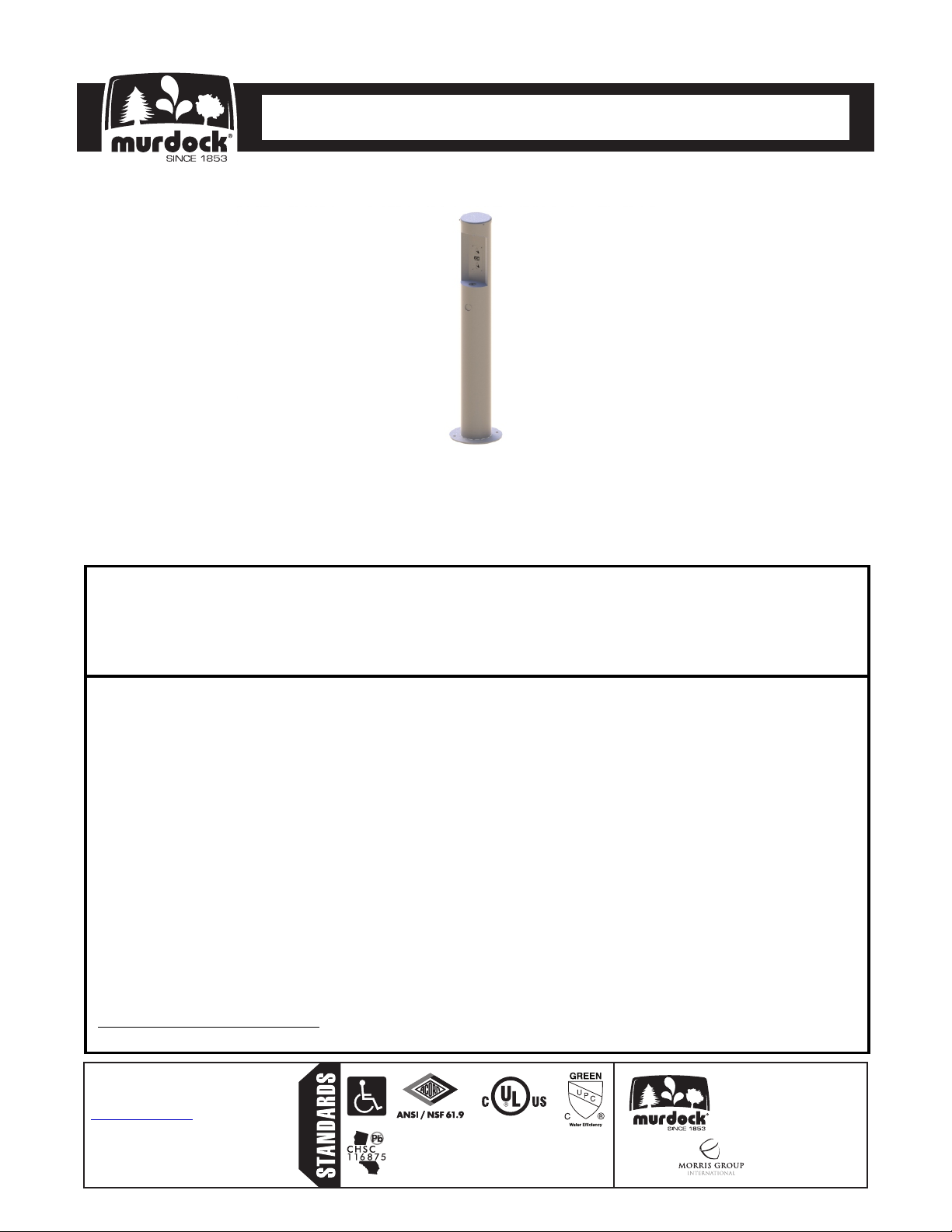
Outdoor Bottle Filler
Pedestal Mounted Sensor/Pushbutton Activation
M-OBF4 / M
-OBFM4
TECHNICAL ASSISTANCE TOLL FREE TELEPHONE NUMBER:
1.800.591.9360
Technical Assistance Fax: 1.626.855.4894
NOTES TO INSTALLER:
1. Please leave this documentation with the owner of the fixture when finished.
2. Please read this entire booklet before beginning the installation.
3. Check your installation for compliance with plumbing, electrical and other applicable codes.
LIMITED WARRANTY - UNITED STATES & CANADA
Murdock warrants that its products are free from defects in material or workmanship under normal use and
service for a period of one year from date of shipment from the factory. Murdocks’s liability under this warranty
shall be discharged solely by repair or replacement of defective material, provided Murdock is notified in writing
within the time periods described above.
This warranty does not cover installation or labor charges and does not apply to materials, which have been
damaged by other causes such as mishandling or improper care or abnormal use. The repair or replacement of
the defective materials shall constitute the sole remedy of the Buyer and the sole remedy of Murdock under this
warranty. Murdock shall not be liable under any circumstances for incidental, consequential or direct charges
caused by defects in the materials, or any delay in the repair or replacement thereof. This warranty is in lieu of
all other warranties expressed or implied. Product maintenance instructions are issued with each unit and
disregard or non-compliance with these instructions will constitute an abnormal use condition and void the
warranty. Stainless steel must be protected on jobsite during construction and must be properly maintained
after the water has been introduced into the water cooler or drinking fountain, or Murdocks’s limited warranty is
void.
LIMITED EXPORT WARRANTY - One year on parts only.
Murdock™ assumes no responsibility for use
of void or superseded data. © Copyright
Murdock Mfg., City of Industry, CA Member of
Morris Group International. Please visit
www.murdockmfg.com
specifications.
7109-602-001 Date: 11/27/17
for most current
COMPLIES WITH
Test rating conditions are
compliant with ARI 1010.
Member of
www.murdockmfg.com
MURDOCK
15125 Proctor Ave.
City of Industry, CA
91746 U.S.A.
Phone 800-591-9360
626-336-4561
Fax 626-855-4894
I N S TA L L AT I O N / M A I N T E N A N C E I N S T R U C T I O N S
Outdoor Bottle Fillers
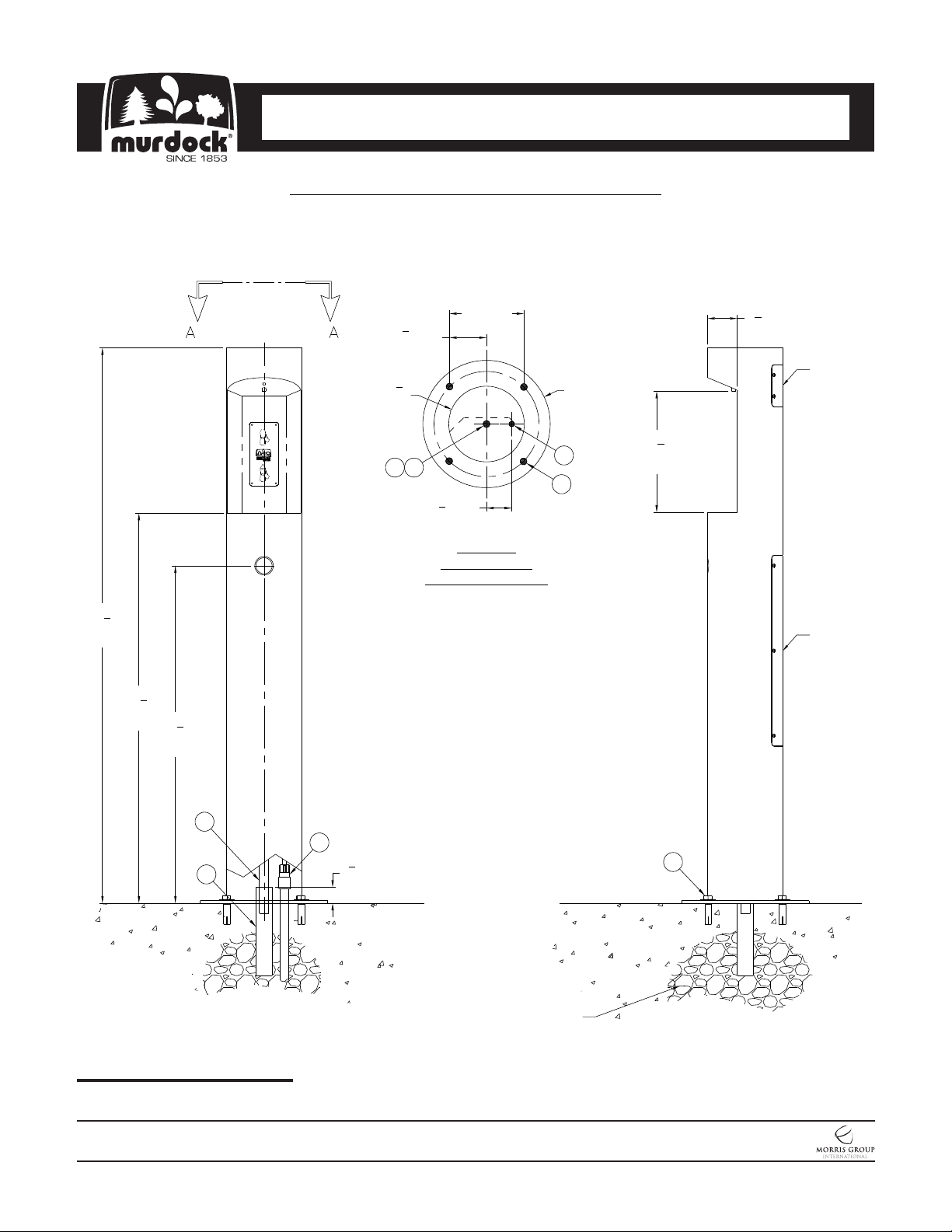
ROUGHING-IN AND DIMENSIONAL DRAWING
Prior to roughing consult with local, state, and federal codes for proper installation.
1
52
4
[1327]
"
3
36
4
[933]
"
3
31
4
[806]
7" [178]
1
3
" [89]
2
TYP
1
Ø7
"
8
[181]
CB
MOUNTING DETAIL
Ø5/8" (4) MOUNTING HOLES IN BASE
A.
FLANGE
1-1/2" NOMINAL DRAIN PIPE, OPEN AT
B.
BOTH ENDS, BY OTHERS
7/8" OD FLEXIBLE DRAIN HOSE
"
C.
1/2" NPTM SUPPLY INLET FLEXIBLE
D.
CONNECTION
ANCHORING HARDWARE, PROVIDEDE.
TYP
3
2
" [60]
8
VIEW A-A
BASE FLANGE
D
A
Ø12"
[305]
3
11
8
[289]
"
2
3
" [70]
4
ACCESS
PANEL
ACCESS
PANEL
C
D
1
1
" [38]
B
GENERAL DIMENSIONS:
1. ALL DIMENSIONS ARE IN INCHES [MM]
2. STOP VALVE NOT PROVIDED
Please visit www.murdockmfg.com
for most current specifications.
2
MIN
GRAVEL DRAIN WELL
3 CUBIC FEET MIN
RECOMMENDED
MURDOCK MFG. • 15125 Proctor Avenue • City of Industry, CA 91746 USA
Phone 800-453-7465 or 626-333-2543 • Fax 626-855-4860 • www.murdockmfg.com
7109-602-001
Page 2 of 11
E
Member of
Revised: 11/27/17
I N S TA L L AT I O N / M A I N T E N A N C E I N S T R U C T I O N S
Outdoor Bottle Fillers
PRIOR TO INSTALLATION:
1. Read all installation instructions carefully, before proceeding.
2. Carefully remove fixture from packaging, preventing scratching or damage.
3. Unit is provided with six (6) AA Alkaline Batteries.
4. Provide mounting surface, sufficient to support the fixture and loads on the fixture. Provide 30” square x 6”
deep minimum concrete slab, provided by others to securely anchor fixture.
5. Provide rough-ins as shown on the roughing-in and dimensional drawing, including Water Supply, Drain Pipe
and Gravel Drain Well. (See page 2 for rough-in details)
6. Completely flush water supply lines of all foreign debris, before connecting to the fixture.
INSTALLATION: (see drainage & mounting roughing-in pg2)
1. Locate the unit over rough-ins on the Mounting Pad, mark mounting holes in base flange.
2. Tilt the unit down on its side, next to the mounting location. Install 1/2”-13 Drop-In Anchors. Optional -IAP (InGround Anchor Plate) which is cast into the concrete, is available.
3. Feed the 7/8” OD Flexible Drain Tube into the open ended Drain Tube. Connect the 1/2” Male NPT Fitting to a
potable water supply. Then tilt the unit into place, making sure that the Tubing is not pinched or kinked. Secure
the Base Flange to the Mounting Pad with provided hardware.
4. Connect the Battery Pack to matching Battery Wire Terminals. When connected the unit is active.
5. Test for leaks and proper operation, and then install the Access Panel.
START UP:
Air within the Bottle Filler System or the structure supply piping will cause an irregular spout outlet stream until
purged out by incoming water. Press and hold Pushbutton until steady water stream is achieved.
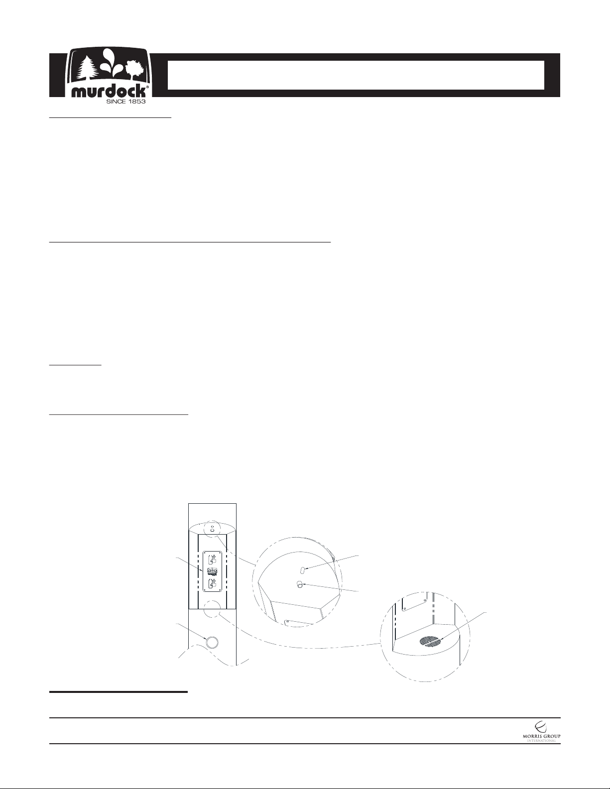
OPERATION INSTRUCTIONS:
Hand operation: Hold container to be filled just below the Filler Tube in the center of the unit, then push
Pushbutton. When the container is almost filled, release the Pushbutton.
Sensor Operation: Hold container to be filled just below the Sensor in the center of the Filler Spout and then
move the container upward and water flow will start automatically. When the container is almost filled, lower the
container below the Sensor until the water stops flowing (see label on the Bottle Filler).
Aluminum Name Plate
Pushbutton
Sensor
Fill Spout
Drain
Please visit www.murdockmfg.com
for most current specifications.
MURDOCK MFG. • 15125 Proctor Avenue • City of Industry, CA 91746 USA
Phone 800-453-7465 or 626-333-2543 • Fax 626-855-4860 • www.murdockmfg.com
7109-602-001
Page 3 of 11
Member of
Revised: 11/27/17
I N S TA L L AT I O N / M A I N T E N A N C E I N S T R U C T I O N S
Outdoor Bottle Fillers
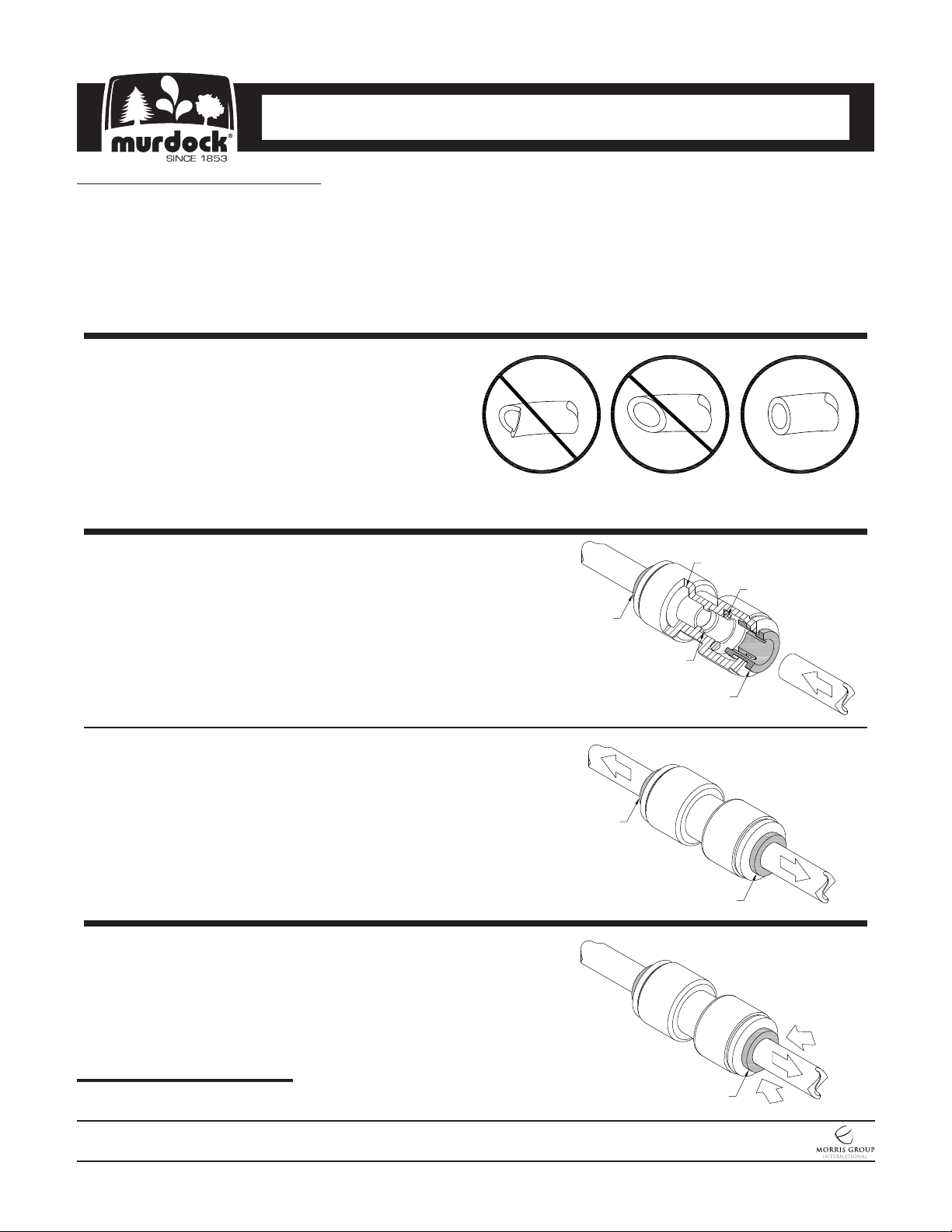
PUSH-IN FITTING INSTALLATION
NOTE: FITTINGS AND TUBE SHOULD BE KEPT
CLEAN, BAGGED AND UNDAMAGED PRIOR
TO INSTALLATION.
TO CUT TUBE:
Cut to fit length of 1/4” Polyethylene (PE) Tubing
and remove any burrs or sharp edges. Ensure
that the outside diameter is free from score
marks. Tube ends should be square.
INSERTING THE TUBE:
1. Firmly and fully insert the Tubing End into the
Push-In Fitting up to the Tube Stop located
approximately 1/2” deep.
O-RING
O-RING
COLLET
2. Pull on the fitted Tubing to ensure it is secure.
Tube should not come free from the Fitting. Water
test the connection assembly prior to leaving the
site to ensure there are no leaks.
DISCONNECTING THE TUBE:
Before disconnecting the Tube from the Fitting,
ensure that the water line is depressurized. Push
Collet square towards the Push-In Fitting Body and
hold. While holding the Collet in, pull on the PE
Tubing to remove from the Push-In Fitting.
Please visit www.murdockmfg.com
for most current specifications.
TUBE STOP
COLLET
COLLET
COLLET
COLLET
MURDOCK MFG. • 15125 Proctor Avenue • City of Industry, CA 91746 USA
Phone 800-453-7465 or 626-333-2543 • Fax 626-855-4860 • www.murdockmfg.com
7109-602-001
Page 4 of 11
Member of
Revised: 11/27/17

I N S TA L L AT I O N / M A I N T E N A N C E I N S T R U C T I O N S
Outdoor Bottle Fillers
TROUBLE SHOOTING:.
1. RESTRICTED OR NO WATER FLOW:
a. Ensure Water Supply service stop valve is fully open.
b. Verify minimum 20 PSIG supply line flow pressure.
c. Check for twist or kinks in spout tubing.
d. Check the water inlet “Y’’ strainer. Sediment from the main supply can get trapped in the
screen along with installation materials such as pipe dope and flux. The screen should be
cleaned and checked on a regular basis and replace if needed.
e. Flow control in solenoid valve outlet elbow clogged remove & clean.
SENSOR TROUBLE SHOOTING:
1. IF LIGHT WITHIN SENSOR DOES NOT FLASH ONCE WHEN USER IS WITHIN RANGE:
a. Verify 9VDC output of battery pack.
b. Replace defective batteries.
c. Sensor in “Security Mode” after 30 seconds of constant detection. Remove source of
detection and wait 30 second before checking.
d. Sensor is picking up a highly reflective surface. Eliminate cause of reflection and wait 30
seconds before checking.
2. IF LIGHT WITHIN SENSOR LENS FLASHES ONCE WHEN THE USER IS WITHIN RANGE:
a. Repair bad connection from sensor to solenoid.
b. There is debris or scale in the solenoid assembly. Remove solenoid, pull out plunger and
spring. Clean with scale remover solution.
c. There is debris or scale in center or two holes in convolution of the water diaphragm.
Remove and clean.
CLEANING & MAINTENANCE GUIDE:
For Powder coated units: Units should be cleaned using a mild soap solution with a sponge or cotton
cloth. Wipe down surfaces then rinse with clean water.
For Stainless steel units:
1. To Remove water spots or rust spots, stainless steel cleaner/polish on a cloth is
recommended.
2. If there are stubborn spots or if you wish to treat a scratch, synthetic abrasive general
purpose pads such as Scotch-Brite™ are recommended.
3. Apply stainless steel cleaner/ polish to the synthetic abrasive pads and carefully rub the
panel in the direction of the grain pattern.
4. DO NOT use harsh chemicals, abrasive or petroleum based cleaners. Use of these will
void the Murdock warranty. DO NOT use abrasives on powder coated units.
5. Stainless steel should be kept clean at all times. If a coating of stainless steel cleaner/
polish is maintained, stainless steel surfaces will retain their new, clean, polished
appearance indefinitely.
Please visit www.murdockmfg.com
for most current specifications.
MURDOCK MFG. • 15125 Proctor Avenue • City of Industry, CA 91746 USA
Phone 800-453-7465 or 626-333-2543 • Fax 626-855-4860 • www.murdockmfg.com
7109-602-001
Page 5 of 11
Member of
Revised: 11/27/17

FILTER CARTRIDGE
REPLACEMENT:
1. Remove six (6) Screws that holds
the Bottom Access Panel to the
unit, this allows access to the Filter.
2. Pull the Filter Assembly straight up
about six (6) inches and then turn
the Small Valve, on the Filter Inlet,
a 1/4 turn to shut off the water
supply to the Filter.
3. While holding the Filter Assembly
up about six (6) inches, unscrew
the lower Filter Cartridge from the
top of the Filter Assembly. Then
move the top of the Filter Assembly
to the side and finish removing the
Filter Cartridge from the unit.
4. Reverse the steps to install a new
Filter Cartridge.
5. Test for leaks and proper operation,
then install the Bottom Access
Panel back onto unit.
I N S TA L L AT I O N / M A I N T E N A N C E I N S T R U C T I O N S
Outdoor Bottle Fillers
WATER INLET
VALVE OPEN
WATER INLET
VALVE CLOSED
REPLACEMENT
CARTRIDGE
Please visit www.murdockmfg.com
for most current specifications.
MURDOCK MFG. • 15125 Proctor Avenue • City of Industry, CA 91746 USA
Phone 800-453-7465 or 626-333-2543 • Fax 626-855-4860 • www.murdockmfg.com
7109-602-001
Page 6 of 11
Member of
Revised: 11/27/17

I N S TA L L AT I O N / M A I N T E N A N C E I N S T R U C T I O N S
Outdoor Bottle Fillers
BATTERY REPLACEMENT:
1. Remove the Bottom Access Panel from the back of the unit and pull the Battery Pack out of the Metal
Battery Box. Do not disconnect the Wires from the Battery Pack unless necessary.
2. Replace the six (6) Alkaline AA Batteries while observing polarity.
3. Put the Battery Pack back in the Metal Box and test for proper operation. Then re-install the Access
Panel.
WIRING DIAGRAM:
SOLENOID
BATTERY PACK
RED WIRES
SENSOR
Please visit www.murdockmfg.com
for most current specifications.
MURDOCK MFG. • 15125 Proctor Avenue • City of Industry, CA 91746 USA
Phone 800-453-7465 or 626-333-2543 • Fax 626-855-4860 • www.murdockmfg.com
7109-602-001
Page 7 of 11
Member of
Revised: 11/27/17

I N S TA L L AT I O N / M A I N T E N A N C E I N S T R U C T I O N S
Outdoor Bottle Fillers
OUTDOOR BOTTLE FILLER PARTS BREAKDOWN DRAWING:
NOTE: See page 11 for table of part numbers corresponding to drawing below.
28
29
30
31
32
33
34
7
8
SENSOR DETAIL
-SO ONLY
1
9
2
3
5
6
17
16
21
18
20
10
7
12
7
15
11
13
14
19
4
35"
Please visit www.murdockmfg.com
for most current specifications.
22
27
26
25
23
24
9
42
MURDOCK MFG. • 15125 Proctor Avenue • City of Industry, CA 91746 USA
Phone 800-453-7465 or 626-333-2543 • Fax 626-855-4860 • www.murdockmfg.com
7109-602-001
Page 8 of 11
Member of
Revised: 11/27/17

I N S TA L L AT I O N / M A I N T E N A N C E I N S T R U C T I O N S
Outdoor Bottle Fillers
OUTDOOR BOTTLE FILLER w/ PET FOUNTAIN PARTS BREAKDOWN DRAWING:
Note: See page 11 for table of part numbers corresponding to drawing below.
28
29
34
30
32
33
31
7
8
9
16
17
SENSOR
DETAIL
18
-SO ONLY
5
1
6
2
3
6
5
20
21
22
9
10
7
12
7
15
11
13
14
19
23
4
35"
1
40
39
38
36
2
3
37
41
4
6"
Please visit www.murdockmfg.com
for most current specifications.
MURDOCK MFG. • 15125 Proctor Avenue • City of Industry, CA 91746 USA
Phone 800-453-7465 or 626-333-2543 • Fax 626-855-4860 • www.murdockmfg.com
7109-602-001
3
10
"
4
4
Page 9 of 11
35
26
24
25
27
42
Member of
Revised: 11/27/17

I N S TA L L AT I O N / M A I N T E N A N C E I N S T R U C T I O N S
Outdoor Bottle Fillers
OUTDOOR PUSHBUTTON BOTTLE FILLER PARTS BREAKDOWN DRAWING:
NOTE: See page 11 for table of part numbers corresponding to drawing below.
7
8
17
1
2
3
5
6
9
16
18
21
12
20
10
7
12
7
15
11
13
14
19
4
35"
Please visit www.murdockmfg.com
for most current specifications.
22
25
42
23
24
9
MURDOCK MFG. • 15125 Proctor Avenue • City of Industry, CA 91746 USA
Phone 800-453-7465 or 626-333-2543 • Fax 626-855-4860 • www.murdockmfg.com
7109-602-001
Page 10 of 11
Member of
Revised: 11/27/17

ITEM #
PART NUMBER DESCRIPTION
I N S TA L L AT I O N / M A I N T E N A N C E I N S T R U C T I O N S
Outdoor Bottle Fillers
Outdoor Bottle Filler Breakdown Table:
Note: See previous page for fixture drawing corresponding to table of parts below.
1 0124-033-000 #8-32 SELF TAPPING SCREW
2 7000-006-000 DRAIN GASKET ADAPTER
3 7003-182-000 DRAIN ADAPTER
4 7013-074-199 7/8" O.D. FLEX DRAIN TUBE
5 7002-125-002 FREEZE RESISTANT PUSHBUTTON
6
7 1895-709-000 ELBOW, 1/4" PUSH-IN x 1/4" STEM
8 JSMBFW18-001 JG PUSH IN/NEOPERL LAMINAR ADAPT M-OBA4
9 0112-001-000 #10-32 X 3/8" HEX SCREW
10 2169-021-199 1/4" O.D. LLDPE TUBING, BLUE x 21"
11 1895-710-000 UNION TEE, 1/4" PUSH-IN
12 2169-003-199 1/4" O.D. LLDPE TUBING, BLUE x 3"
13 2169-006-199 1/4" O.D. LLDPE TUBING, BLUE x 6"
14 2169-030-199 1/4" O.D. LLDPE TUBING, BLUE x 30"
15 2169-007-199 1/4" O.D. LLDPE TUBING, BLUE x 5"
16 7000-021-000 YS-F "Y" STRAINER, 1/4" NPT
17 1895-125-000 1/4" O.D. x 1/4" NPT PUSH-IN FITTING
18 7000-420-000 1/4 TURN SHUTOFF VALVE
19 7012-313-000 REPLACEMENT FILTER CARTRIDGE
20 2169-017-199 1/4" O.D. LLDPE TUBING, BLUE x 17"
21 1895-123-000 1/4" x 3/8" O.D. TUBE UNION PUSH-IN
22 1895-005-000 3/8" O.D. TUBE x 1/2" NPT MALE CONNECTER
23 2170-002-500 3/8" O.D. LOW DENSITY PE TUBING x 2.5"
24 0112-011-000 #10-32 x 3/8" CENTER REJECT SCREW
25 2570-101-001 REPLACEMENT NON-METERING AIR-TROL VALVE
26 2570-130-001 9-12 VDC SOLENOID OP VALVE ASSEMBLY
27 7013-046-001 6 AA BATTERY PACK
28 0302-003-000 #8-32 HEX NUT
29 6527-108-000 #8 INTERNAL TOOTH LOCK WASHER
30 0331-023-000 #8 STN. STL. FLAT WASHER
31 7013-010-199 NANO SENSOR BRACKET
32 7013-019-199 FOAM TAPE
33 7013-057-002 NANO SPACER ASSEMBLY
34 7013-009-001 NANO SENSOR SPACER
35 7013-049-001 PET FOUNTAIN ASSEMBLY
36 7007-008-99 PET FOUNTAIN STRAINER
37 7013-049-002 PET FOUNTAIN BOWL ASSEMBLY
38 7013-063-199 3/8" STAINLESS STEEL PIPE
39 2361-011-000 3/8" NPT x 1/4" NPT FEMALE REDUCER
40 1895-125-000 1/4" NPT x 1/4" O.D. PUSH-IN CONNECTION
41 4102-250-000 5/8" BARBED TEE
42 7002-021-001 ANCHORING HARDWARE PACKAGE
2566-025-002 SIDE OUTLET PUSHBUTTON ASSEMBLY
2566-050-002 BACK OUTLET PUSHBUTTON ASSEMBLY
Please visit www.murdockmfg.com
for most current specifications.
MURDOCK MFG. • 15125 Proctor Avenue • City of Industry, CA 91746 USA
Phone 800-453-7465 or 626-333-2543 • Fax 626-855-4860 • www.murdockmfg.com
7109-602-001
Page 11 of 11
Member of
Revised: 11/27/17
 Loading...