

Murdock BF158, BF168 Maintance Manual
Surface Mounted Bottle Fillers
I N S TA L L AT I O N / M A I N T E N A N C E I N S T R U C T I O N S
Pushbutton
Actuated
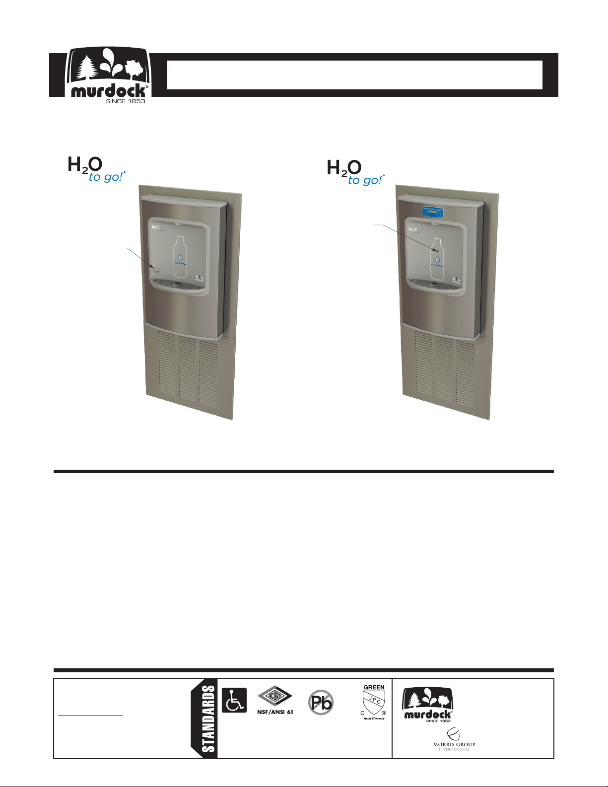
BF158 & BF168 Series
Stand-Alone Refrigerated Wall Mount
Sensor Operated Bottle Filler
Sensor
Operated
BF158 Series BF168 Series
Please visit www.murdockmfg.com
for most current specifications.
TABLE OF CONTENTS
Dimensional Data/Rough-Ins . . . . . . . . . . . . . . . . . . . . . . . . . . . . . . . . . . . . . . . . . . . . . . . 2
Important/Prior to Installation Information. . . . . . . . . . . . . . . . . . . . . . . . . . . . . . . . . . . . . . 3
Push-In Fitting Installation . . . . . . . . . . . . . . . . . . . . . . . . . . . . . . . . . . . . . . . . . . . . . . . . . 4
Pre-Installation. . . . . . . . . . . . . . . . . . . . . . . . . . . . . . . . . . . . . . . . . . . . . . . . . . . . . . . . . 5-6
Frame Installation . . . . . . . . . . . . . . . . . . . . . . . . . . . . . . . . . . . . . . . . . . . . . . . . . . . . . . 7-8
Chiller Supply Connections . . . . . . . . . . . . . . . . . . . . . . . . . . . . . . . . . . . . . . . . . . . . . . 9-11
Bottle Filler Installation . . . . . . . . . . . . . . . . . . . . . . . . . . . . . . . . . . . . . . . . . . . . . . . . 12-16
Chiller Lower Trim Installation. . . . . . . . . . . . . . . . . . . . . . . . . . . . . . . . . . . . . . . . . . . . . . 17
Bottle Filler BF158 Startup . . . . . . . . . . . . . . . . . . . . . . . . . . . . . . . . . . . . . . . . . . . . . . . . 18
Bottle Filler BF168 Startup & Optional -BCD Bottle Counter Display . . . . . . . . . . . . . 19-20
Troubleshooting . . . . . . . . . . . . . . . . . . . . . . . . . . . . . . . . . . . . . . . . . . . . . . . . . . . . . . . . 21
Repair Parts. . . . . . . . . . . . . . . . . . . . . . . . . . . . . . . . . . . . . . . . . . . . . . . . . . . . . . . . . 22-25
Warranty Information . . . . . . . . . . . . . . . . . . . . . . . . . . . . . . . . . . . . . . . . . . . . . . . . . . . . 26
Murdock™ assumes no responsibility for use
of void or superseded data. © Copyright
Murdock Mfg., City of Industry, CA Member of
Morris Group International. Please visit
www.murdockmfg.com for most current
specifications.
7020-969-001
12/11/18
COMPLIES WITH
Federal
Public Law
111-380
(No Lead)
Member of
www.murdockmfg.com
MURDOCK
15125 Proctor Ave.
City of Industry, CA
91746 U.S.A.
Phone 800-591-9360
626-336-4561
Fax 626-855-4894
Surface Mounted Bottle Fillers
I N S TA L L AT I O N / M A I N T E N A N C E I N S T R U C T I O N S
IMPORTANT
This fixture is intended to dispense water that has been lowered in temperature, but otherwise remains
unchanged by the materials in the Bottle Filler. It is common for electrical equipment to be grounded to water
lines either within a structure or away from it. Every attempt should be made to prevent this kind of grounding
from generating electrical feedback into the Bottle Filler creating electrolysis. Electrolysis will cause a metallic
taste or cause water metal content to increase.
NOTICE
A dielectric coupling must be used to connect the Bottle Filler to the water supply. A nonmetallic coupler is
furnished with this Bottle Filler to meet this requirement.
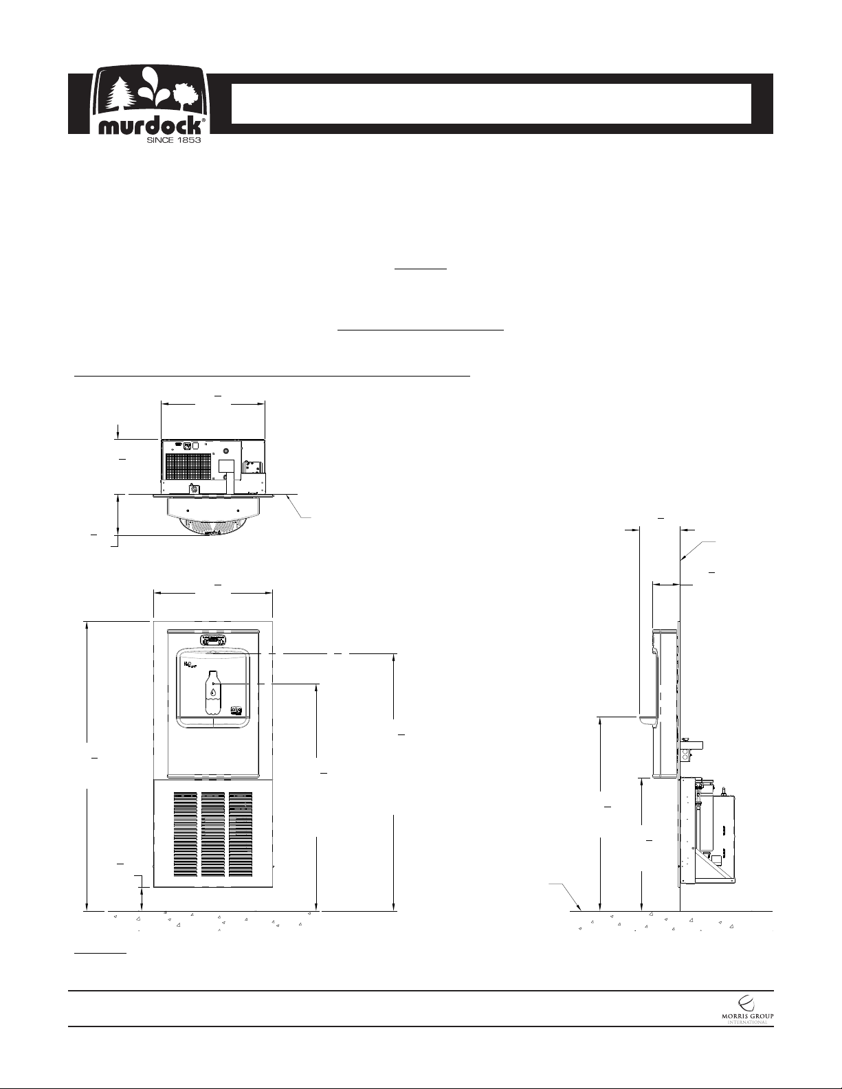
DIMENSIONAL DRAWING
Prior to roughing in, consult with local, state, and federal codes for proper mounting height.
BF158/168 Stand-Alone Refrigerated Wall Mount Bottle Filler
10
5
20
"
8
[524]
7
"
8
General Notes:
1. All dimensions are in inches [mm]
2. Dimensions shown are for recommended adult
*
height. Adjust vertical dimensions as necessary
to comply with Federal, State & Local Codes
[276]
1
8
"
8
Ref. Wall
1
8
8
[206]
"
Ref. Wall
[206]
1
5
23
3
"
4
2
[140]
"
[603]
1
*51
"
5
*57
8
[1464]
"
*4
[121]
1
*45
"
4
[1149]
Sensor
Height
3
"
4
4
[1149]
Bottle Filler
Discharge
Height
Finished
Floor
*38
[981]
5
"
8
1
*26
"
2
[673]
NOTES: Dimensions shown for Adult ADA compliant installation. For Child ADA compliant parallel approach
installation, decrease height of installation by 3 inches. Provide clear floor space as required. Adjust vertical
dimensions as required to comply with federal, state, and local codes.
MURDOCK MFG. • 15125 Proctor Avenue • City of Industry, CA 91746 USA
Phone 800-453-7465 or 626-333-2543 • Fax 626-855-4860 • www.murdockmfg.com
7020-969-001
Page 2 of 26
Member of
Revised: 12/11/2018
Surface Mounted Bottle Fillers
I N S TA L L AT I O N / M A I N T E N A N C E I N S T R U C T I O N S
IMPORTANT:
1. Water Supply Service Stop Valve, Water Connections and Electrical Connections to be supplied by others in
accordance with local codes.
2. Provide 4” minimum clear space in front of Bottom Trim Panel and above In-Wall Chiller to allow for proper
ventilation.
3. Waste is 1-1/4” Outer Diameter. Chiller water inlet is 3/8” Outer Diameter copper tube. Chiller water outlet is
3/8” Outer Diameter copper tube. Drinking Fountain water inlet is 3/8” Outer Diameter copper tube. Bottle
Filler water inlet is 3/8” Outer Diameter copper tube. Water line from in-wall chiller to drinking fountain must
have adequate insulation, provided by installer.
4. Completely flush supply lines of all foreign debris before connecting to fixture. A dielectric coupler must be
used to connect the drinking fountain to the water supply. A non-metallic coupler is furnished with this unit to
make this ROP. Water cooler designed to not cause problems with taste, odor, color, or sediment. Optional
Water Filter, is available should any of these problems arise from the water supply.
5. Do NOT solder Tubes inserted into the Chiller or Bottle Filler as damage to the O-Rings on the Push-In
Fittings may result.
6. All burrs must be removed from outside of cut tubes before inserting into strainer or other components.
7. Power supply must be identical in voltage, cycle and phase to that specified on the chiller data plate. Refer to
submittal.
8. This unit must be grounded per the requirements of applicable electrical codes.
9. WARNING: Warranty is void if installation is not made following current Murdock Mfg. installation instructions
and if components are assembled to the fixture that are not approved by Murdock Mfg.
10. Fixture operates within water pressure range of 25 PSIG (174 kPa) to 105 PSIG (724 kPa). Murdock Mfg. will
not warranty chiller damaged when connected to supply lines with flow pressure lower than 25 PSIG (174
kPa) or higher than 105 PSIG (724 kPa). A pressure regulator must be furnished by others on supply line if
inlet pressure is greater than 105 PSIG (724 kPa). 40-60 PSI is recommended.
11. Due to cold waste water, Murdock Mfg. recommends that waste piping supplied by installer be insulated
appropriately to prevent excessive condensation.
12. Per UPC 609.10-All building water supply systems in which quick acting valves are installed shall be
provided with devices to absorb the hammer caused by high pressure resulting from the quick closing of the
valve. These pressure-absorbing devices shall be approved mechanical devices. Water pressure-absorbing
devices shall be installed as close as possible to the quick closing valve
PRIOR TO INSTALLATION:
1. Read all installation instructions carefully, before proceeding.
2. Carefully remove all fixture components from packaging, preventing scratching or damage. Inspect fixture and
all parts from damages and all parts that are bolted on.
3. Provide mounting surface, adequate to support the fixture and loads on the fixture.
4. Provide rough-ins as shown on the roughing-in and dimensional drawing, including water supply, drain pipe
and gravel drain well. (See rough-in details)
5. It is common for electrical equipment to be grounded to water lines either within a structure or away; otherwise,
remains unchanged by the materials in the water cooler. Every attempt should be made to prevent this kind of
grounding from generating feedback into the water cooler creating electrolysis. Electrolysis will cause a
metallic taste or cause water metal content to increase.
6. Electrical Receptacle(s) must be wired to a GFCI protected circuit. Fixture must be earth grounded per NEC
(National Electrical Code).
7. Completely flush water supply lines of all foreign debris, before connecting to the fixture.
MURDOCK MFG. • 15125 Proctor Avenue • City of Industry, CA 91746 USA
Phone 800-453-7465 or 626-333-2543 • Fax 626-855-4860 • www.murdockmfg.com
7020-969-001
Page 3 of 26
Member of
Revised: 12/11/2018

Surface Mounted Bottle Fillers
I N S TA L L AT I O N / M A I N T E N A N C E I N S T R U C T I O N S
PUSH-IN FITTING INSTALLATION
NOTE: FITTINGS AND TUBE SHOULD BE KEPT
CLEAN, BAGGED AND UNDAMAGED PRIOR TO
INSTALLATION.
TO CUT TUBE:
Cut to fit length of 1/4” PE Tubing and remove any
burrs or sharp edges. Ensure that the outside diameter
is free from score marks. Tube ends should be square.
INSERTING THE TUBE:
1. Firmly and fully insert the Tubing end into the Push-In
Fitting up to the Tube Stop located approximately 1/2”
deep.
2. Pull on the fitted Tubing to ensure it is secure. Tube
should not come free from the Fitting. Water test the
connection assembly prior to leaving the site to ensure
there are no leaks.
DISCONNECTING THE TUBE:
Prior to disconnecting the Tube from the Fitting, ensure
that the water line is depressurized. Push Collet Square
towards the Push-In Fitting Body and hold. While holding
the Collet in, pull on the PE Tubing to remove from the
Push-In Fitting.
O-RING
O-RING
COLLET
TUBE STOP
COLLET
COLLET
COLLET
MURDOCK MFG. • 15125 Proctor Avenue • City of Industry, CA 91746 USA
Phone 800-453-7465 or 626-333-2543 • Fax 626-855-4860 • www.murdockmfg.com
7020-969-001
Page 4 of 26
COLLET
Member of
Revised: 12/11/2018
Surface Mounted Bottle Fillers
I N S TA L L AT I O N / M A I N T E N A N C E I N S T R U C T I O N S
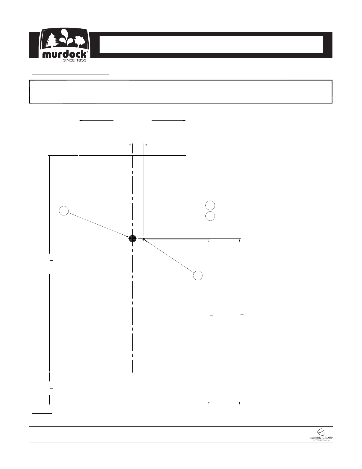
Pre-Installation
Provide wall opening as indicated in rough-in detail provided, ensuring to block out and provide structural support to allow
Frame to be anchored with installer provided anchoring hardware for Ø1/4" anchoring holes provided.
1
1
3
38
"
8
BLOCKOUT
19"
BLOCKOUT
C
L
2"
General Notes:
1. Dimension indicated with (**) is for 33"
Drinking Fountain discharge height. If
discharge height differs, adjust
accordingly.
2. To accommodate Chiller, wall depth
must be 11" minimum.
3. For Sensor fixture, 2" x 4" Electrical
Plug-In Receptacle to be located and
supplied by others in accordance with
local codes.
1-1/4" P-Trap Waste Outlet
1
3/8" OD Supply Inlet
2
1
3
29
"
8
SUPPLY
INLET
7
*5
"
8
FINISHED FLOOR
NOTES: Dimensions shown for Adult ADA compliant installation. For Child ADA compliant parallel approach installation,
decrease height of installation by 3 inches. Provide clear floor space as required. Adjust vertical dimensions as required to
comply with federal, state, and local codes.
MURDOCK MFG. • 15125 Proctor Avenue • City of Industry, CA 91746 USA
Phone 800-453-7465 or 626-333-2543 • Fax 626-855-4860 • www.murdockmfg.com
7020-969-001
Page 5 of 26
1
29
"
2
WASTE
OUTLET
Member of
Revised: 12/11/2018
Surface Mounted Bottle Fillers
I N S TA L L AT I O N / M A I N T E N A N C E I N S T R U C T I O N S
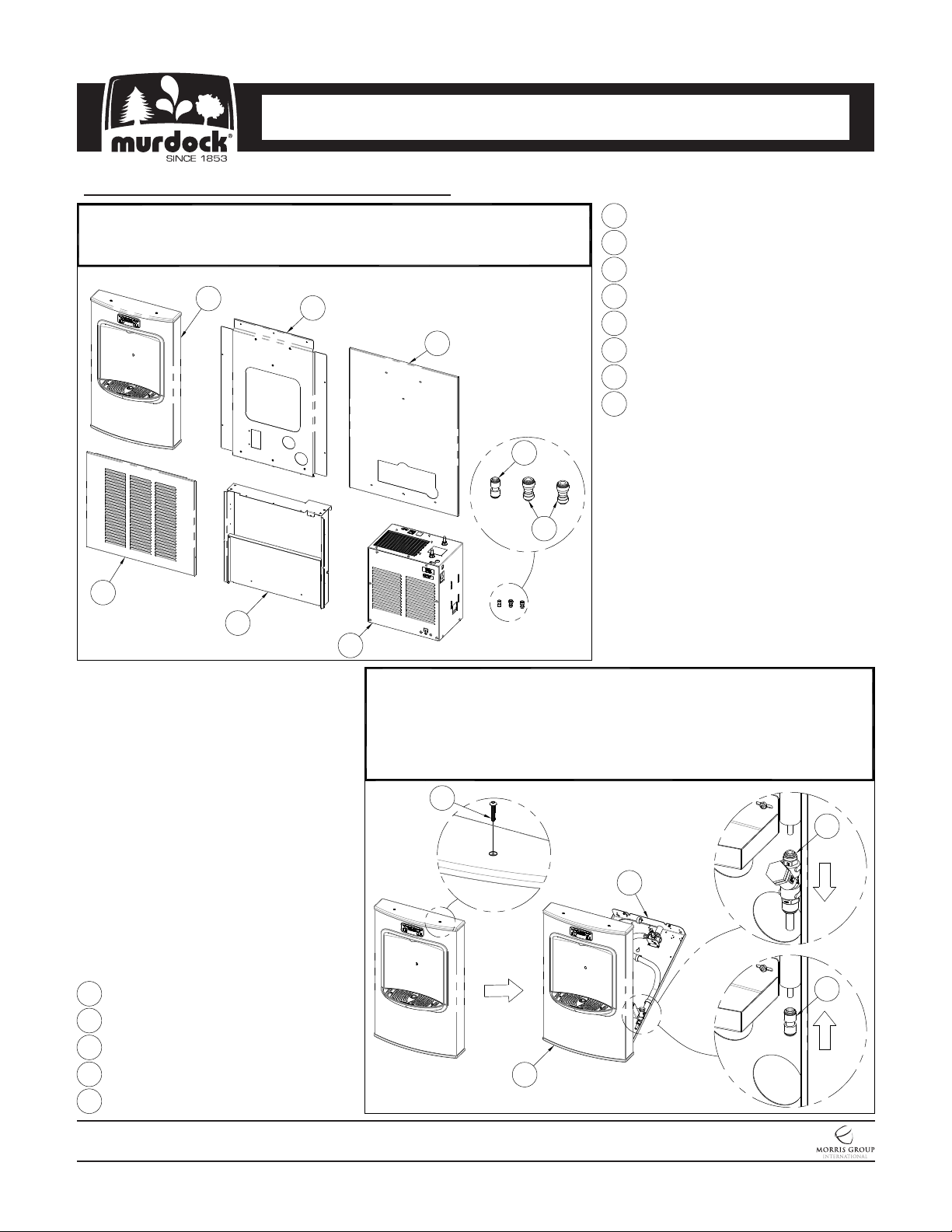
Pre-Installation (Continued)
Remove Bi-Level Mounting Frame, Chiller Mounting Frame, Panels,
2
Anchoring Clips and Screws from packaging, careful to avoid damage to
fixture and fixture sub assemblies.
1
2
3
BF15/BF16 Bottle Filler
1
Bottle Filler Mounting Panel
2
Upper Trim Panel
3
Bottom Trim Panel
4
Chiller Mounting Frame Assembly
5
8 GPH Chiller Assembly
6
1/4" x 3/8" OD Tube Union Push-In
7
1/4" OD Tube Union Connector
8
8
7
4
5
#10-32 x 1" Allen Button Head Screw
1
Bottle Filler Housing
2
Mounting Panel
3
Y-Strainer
4
1/4" ID Union Connector
5
6
Retrieve Bottle Filler Assembly and place unit onto a horizontal surface.
3
Unscrew Top Screws with 1/8" Allen Wrench (not included) and place in a
secure location for later use. Open unit by swinging Mounting Panel down.
With unit open, remove and replace Y-Strainer with 1/4" ID Union
Connector. Once completed, place Bottle Filler and Y-Strainer in a secure
location for future use in installation manual.
1
4
3
5
2
MURDOCK MFG. • 15125 Proctor Avenue • City of Industry, CA 91746 USA
Phone 800-453-7465 or 626-333-2543 • Fax 626-855-4860 • www.murdockmfg.com
7020-969-001
Page 6 of 26
Member of
Revised: 12/11/2018
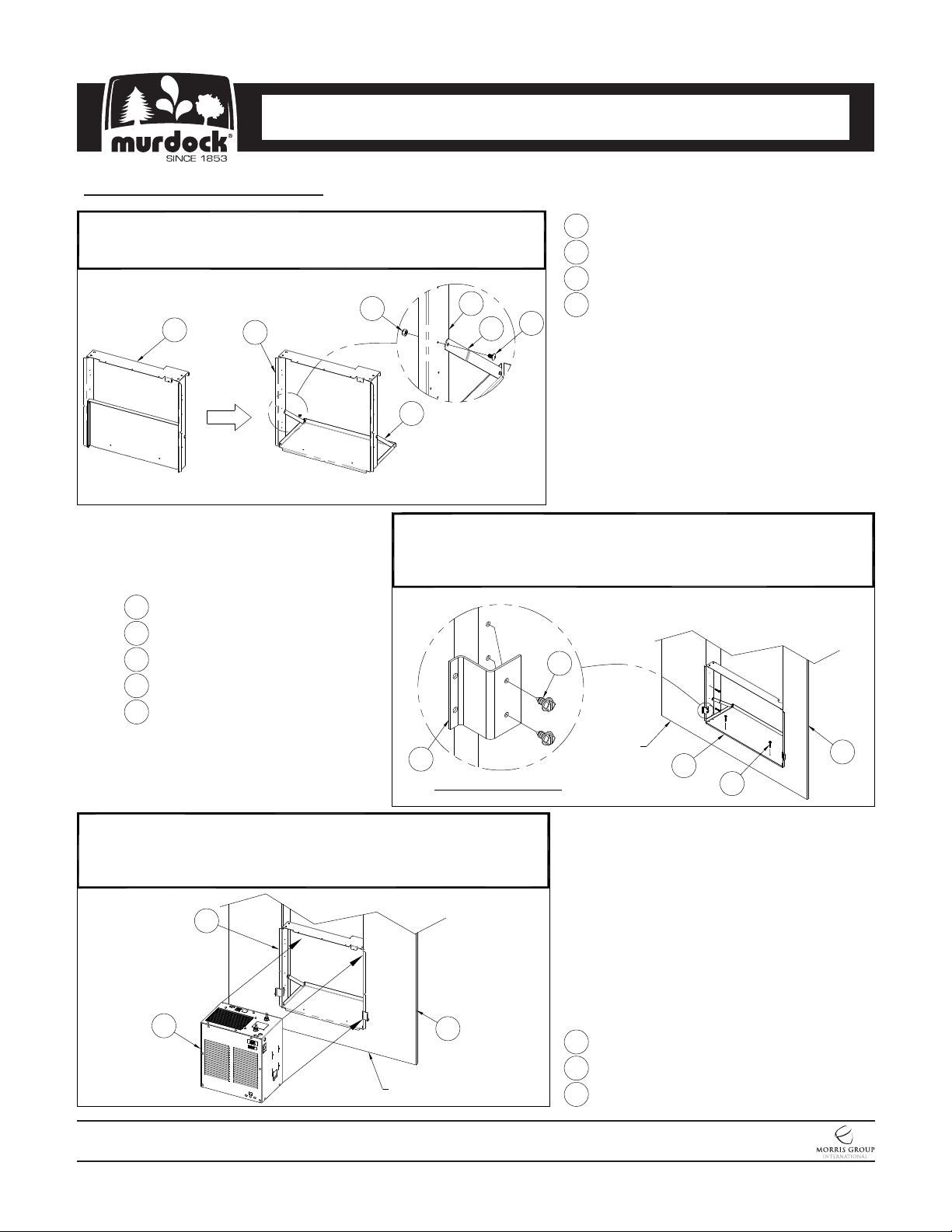
Frame Installation
Surface Mounted Bottle Fillers
I N S TA L L AT I O N / M A I N T E N A N C E I N S T R U C T I O N S
Rotate Chiller Shelf to full depth and fix to frame, anchoring Support
1
Struts using #10-32 Phillips Head Screws and Hex Head Locknuts
provided before continuing.
2
Position Chiller Frame Assembly within prepared opening with sides and
bottom lips overlapping against the finished wall. Anchor Chiller Frame
Assembly to block out being sure to keep Frame level and square. 1/8"
holes provided for Anchoring Hardware, provided by installer.
Anchoring Clip Detail
4
Folded
Trim Panel Mounting Bracket
1
#8 x 3/8" Hex Head Screw
2
Reference Wall
3
Chiller Mounting Frame Assembly4
Anchoring Hardware (By Others)5
1
2
4
Assembled
2
1
#10-32 Hex Head Locknut
1
Chiller Shelf Mounting Frame
2
#10-32 Phillips Head Screw
3
Chiller Shelf Support Strut4
3
4
2
Finished
Floor
4
2
3
With Chiller Mounting Frame Assembly Secured, position and center 8
3
GPH Chiller Assembly onto Chiller Mounting Frame Assembly.
Anchoring is not required for Chiller Assembly. Connect Chiller
Electrical (See Chiller Manual).
2
3
Finished
Floor
MURDOCK MFG. • 15125 Proctor Avenue • City of Industry, CA 91746 USA
Phone 800-453-7465 or 626-333-2543 • Fax 626-855-4860 • www.murdockmfg.com
7020-969-001
1
Page 7 of 26
Reference Wall
1
Chiller Mounting Frame Assembly
2
8 GPH Chiller Assembly
3
Member of
Revised: 12/11/2018
Surface Mounted Bottle Fillers
I N S TA L L AT I O N / M A I N T E N A N C E I N S T R U C T I O N S
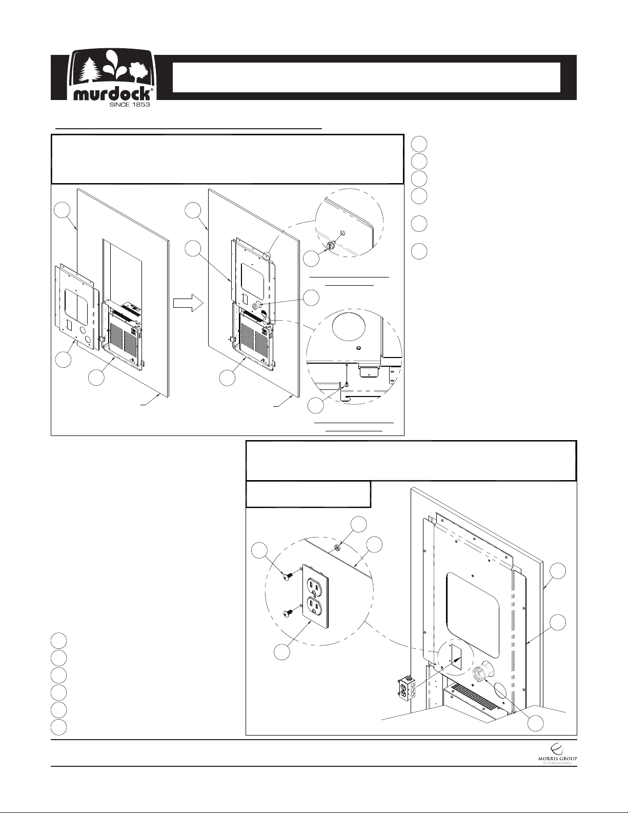
Frame Installation (Continued)
Position Mounting Panel on Mounting Frame by utilizing the Lower Flange on the
4
Mounting Panel. Center and secure with #8-3/8" Phillips Sheet Metal Screws.
With Mounting Panel secured, Anchor Mounting Panel to finished wall with
anchoring hardware provided by others for Ø7/32" holes.
3
1
2
Finished
Floor
3
1
2
Finished
Floor
5
Anchoring Mounting Panel
to Finished Wall
6
4
Anchoring Mounting Panel
to Mounting Frame
Mounting Panel
1
Chiller Mounting Frame Assembly
2
Reference Wall
3
#8 x 3/8" Phillips Sheet Metal Screw
4
(Qty. 3)
Anchoring Hardware
5
(Qty. 7, provided by others)
1-1/4" Compression Adapter6
Stubbed out (provided by others)
Mounting Panel
1
Junction Box Assembly
2
#10-32 x 1/2" Truss Head Screw
3
#10-32 Hex Nut
4
Reference Wall
5
Rough-In Plumbing, by others
6
With Mounting Panel Secured, mount Junction Box Assembly to Mounting
5
Panel. Secure Junction Box Assembly with #10-32 x 1/2" Truss Head
Screw and #10-32 Hex Nut.
BF168 ONLY
4
3
2
5
5
1
6
MURDOCK MFG. • 15125 Proctor Avenue • City of Industry, CA 91746 USA
Phone 800-453-7465 or 626-333-2543 • Fax 626-855-4860 • www.murdockmfg.com
7020-969-001
Page 8 of 26
Member of
Revised: 12/11/2018
 Loading...