

Murdock BF11, BF12 Maintance Manual
Cooler Mounted Bottle Fillers
I N S TA L L AT I O N / M A I N T E N A N C E I N S T R U C T I O N S
BF11 & BF12 Bottle Filler Series
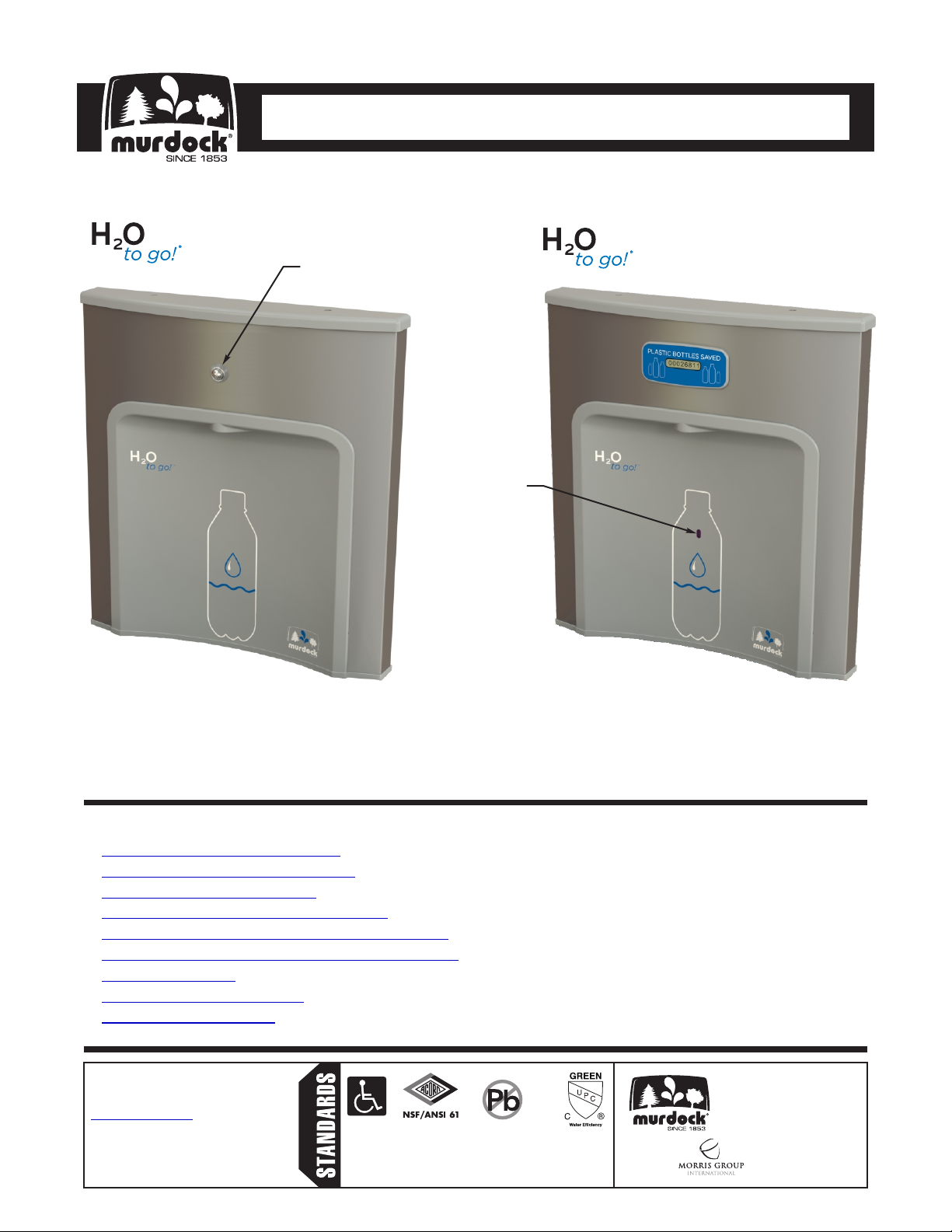
Pushbutton
Actuated
Sensor
Operated
BF11
Please visit www.murdockmfg.com
for most current specifications.
BF12
TABLE OF CONTENTS
Dimensional Data/Rough-Ins. . . . . . . . . . . . . . . . . . . . . . . . . . . . . . . . . . . . . . . . . . . . . . . . 2
. . . . . . . . . . . . . . . . . . . . . . . . . . . . . . . . . . . . . . . . . . . . . . 3Prior to Installation Information
. . . . . . . . . . . . . . . . . . . . . . . . . . . . . . . . . . . . . . . . . . . . . . . . . . 4Push-In Fitting Installation
. . . . . . . . . . . . . . . . . . . . . . . . . . . . . . . . . . . . . . . . . 5-11BF11/BF12 Bottle Filler Installation
. . . . . . . . . . . . . . . . . . . . . . . . . . . . . . . . . . . . 12BF11/BF12 Water Supply Tubing Diagram
. . . . . . . . . . . . . . . . . . . . . . . . . . . . . . . . . 13-14Optional -BCD Bottle Filler Counter Display
. . . . . . . . . . . . . . . . . . . . . . . . . . . . . . . . . . . . . . . . . . . . . . . . . . . . . . . . . 15Troubleshooting
. . . . . . . . . . . . . . . . . . . . . . . . . . . . . . . . . . . . . . . . . . . . . . . . 16-18BF11/BF12 Repair Parts
. . . . . . . . . . . . . . . . . . . . . . . . . . . . . . . . . . . . . . . . . . . . . . . . . . . . . 19Warranty Information
Murdock™ assumes no responsibility for use
of void or superseded data. © Copyright
Murdock Mfg., City of Industry, CA Member of
Morris Group International. Please visit
www.murdockmfg.com for most current
specifications.
7020-956-001
Date: 12/11/18
COMPLIES WITH
Federal
Public Law
111-380
(No Lead)
Member of
www.murdockmfg.com
MURDOCK
15125 Proctor Ave.
City of Industry, CA
91746 U.S.A.
Phone 800-591-9360
626-336-4561
Fax 626-855-4894
Cooler Mounted Bottle Fillers
I N S TA L L AT I O N / M A I N T E N A N C E I N S T R U C T I O N S
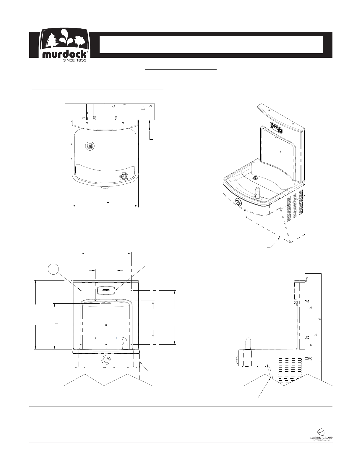
DIMENSIONAL DRAWING
Prior to roughing in, consult with local, state, and federal codes for proper mounting height.
Note: Rough-Ins are the same for BF11 & BF12
1
3
"
8
[79]
1
18
"
2
[470]
14"
[356]
6"
[152]
1
19
8
[486]
2
"
5
12
"
8
[321]
General Notes:
1. All dimensions are in inches [MM]
Optional -BCD
Bottle Counter
and Filter
Status Display
3
10
[264]
15"
"
8
[381]
Existing Fixture
Existing Fixture
Existing Fixture
2. Ø1/4" Holes, 10 Places for Anchoring Hardware,
provided by others
MURDOCK MFG. • 15125 Proctor Avenue • City of Industry, CA 91746 USA
Phone 800-453-7465 or 626-333-2543 • Fax 626-855-4860 • www.murdockmfg.com
7020-956-001
Page 2 of 19
Member of
Revised: 12/11/18
Cooler Mounted Bottle Fillers
I N S TA L L AT I O N / M A I N T E N A N C E I N S T R U C T I O N S
PRIOR TO INSTALLATION:
1. Some options may slightly alter installation. To ensure proper installation, review the Manual thoroughly and verify
rough-ins before beginning any work. File this Manual with the owner or maintenance personnel upon completion
of installation.
2. Carefully remove all fixture components from packaging, preventing scratching or damage. Inspect fixture and all
parts for damage.
3. Provide rough-ins as shown on the roughing-in and dimensional drawing. (See rough-in details)
4. Water Supply Service Stop Valve, Water Connections and Electrical Connections to be supplied and installed by
others in accordance with local codes.
5. Fixture mounting requirements: Industry standard wall construction, adequate to support the fixture and wall
anchors (installer provided) sufficient to secure the fixture.
6. Fixture operates within water pressure range of 20 to 105 PSIG. Murdock will not warranty fixtures damaged
when connected to supply lines with flow pressure lower than 20 PSIG or higher than 105 PSIG.
7. Water Supply inlet is 1/4” OD Polyethylene (PE) Tube.
8. Per UPC 609.10-All building water supply systems in which quick-closing Valves are installed shall be provided
with devices to absorb the hammer caused by high pressure resulting from the quick-closing of the Valve. These
pressure-absorbing devices shall be approved mechanical devices. Water pressure-absorbing devices shall be
installed as close as possible to the quick-closing Valve.
9. Completely flush supply of all foreign debris before connecting to fixture. Bottle Filler is designed to provide
trouble free drinking water unaffected by fixture connection tubing and fittings and will not cause problems with
taste, odor, color or sediment.
MURDOCK MFG. • 15125 Proctor Avenue • City of Industry, CA 91746 USA
Phone 800-453-7465 or 626-333-2543 • Fax 626-855-4860 • www.murdockmfg.com
7020-956-001
Page 3 of 19
Member of
Revised: 12/11/18
Cooler Mounted Bottle Fillers
I N S TA L L AT I O N / M A I N T E N A N C E I N S T R U C T I O N S
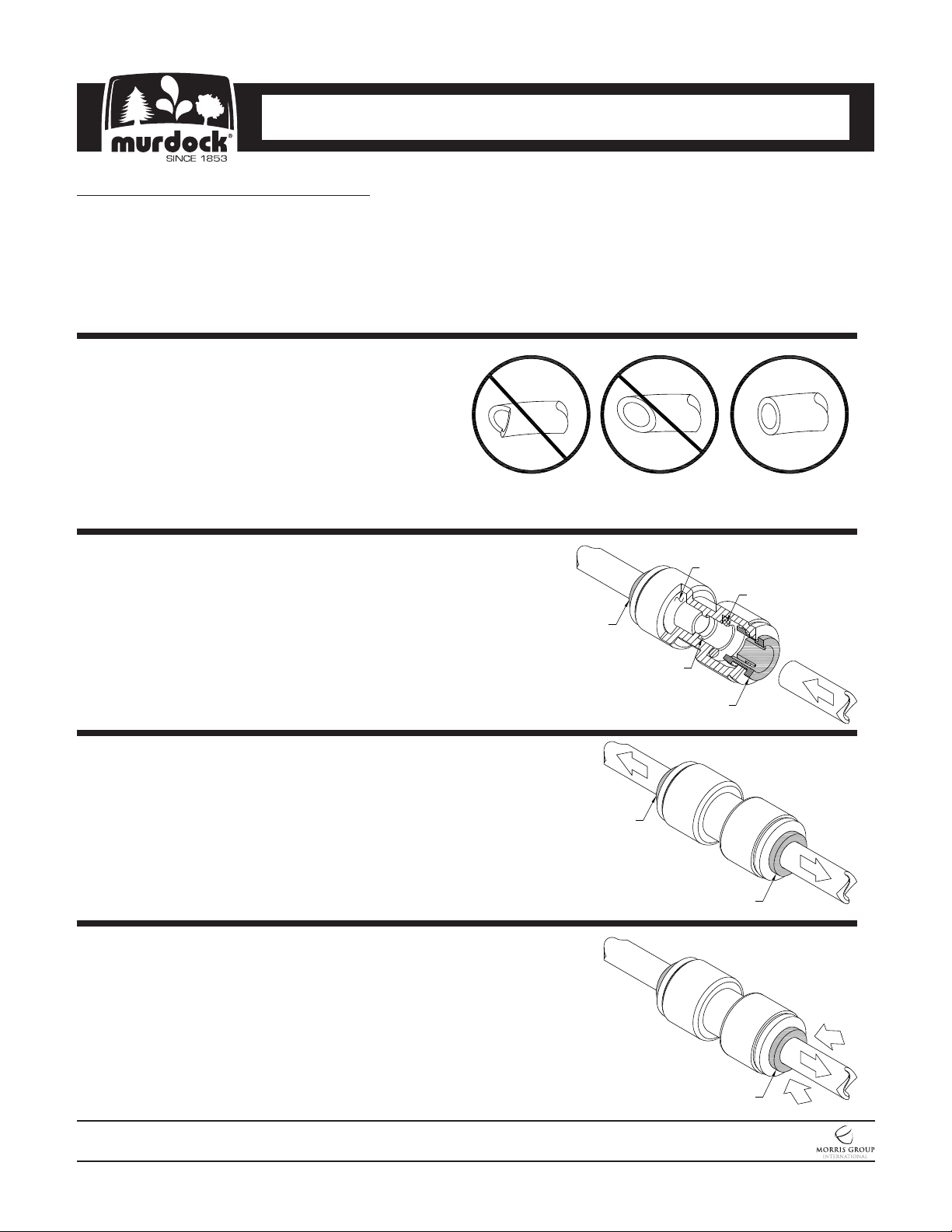
PUSH-IN FITTING INSTALLATION
NOTE: FITTINGS AND TUBE SHOULD BE KEPT
CLEAN, BAGGED AND UNDAMAGED PRIOR TO
INSTALLATION.
TO CUT TUBE:
Cut to fit length of 1/4” PE Tubing and remove any
burrs or sharp edges. Ensure that the outside diameter
is free from score marks. Tube ends should be square.
INSERTING THE TUBE:
1. Firmly and fully insert the Tubing end into the Push-In
Fitting up to the Tube Stop located approximately 1/2”
deep.
2. Pull on the fitted Tubing to ensure it is secure. Tube
should not come free from the Fitting. Water test the
connection assembly prior to leaving the site to ensure
there are no leaks.
DISCONNECTING THE TUBE:
Prior to disconnecting the Tube from the Fitting, ensure
that the Water Line is depressurized. Push Collet Square
towards the Push-In Fitting Body and hold. While holding
the Collet in, pull on the PE Tubing to remove from the
Push-In Fitting.
O-RING
O-RING
COLLET
TUBE STOP
COLLET
COLLET
COLLET
MURDOCK MFG. • 15125 Proctor Avenue • City of Industry, CA 91746 USA
Phone 800-453-7465 or 626-333-2543 • Fax 626-855-4860 • www.murdockmfg.com
7020-956-001
Page 4 of 19
COLLET
Member of
Revised: 12/11/18
Cooler Mounted Bottle Fillers
I N S TA L L AT I O N / M A I N T E N A N C E I N S T R U C T I O N S
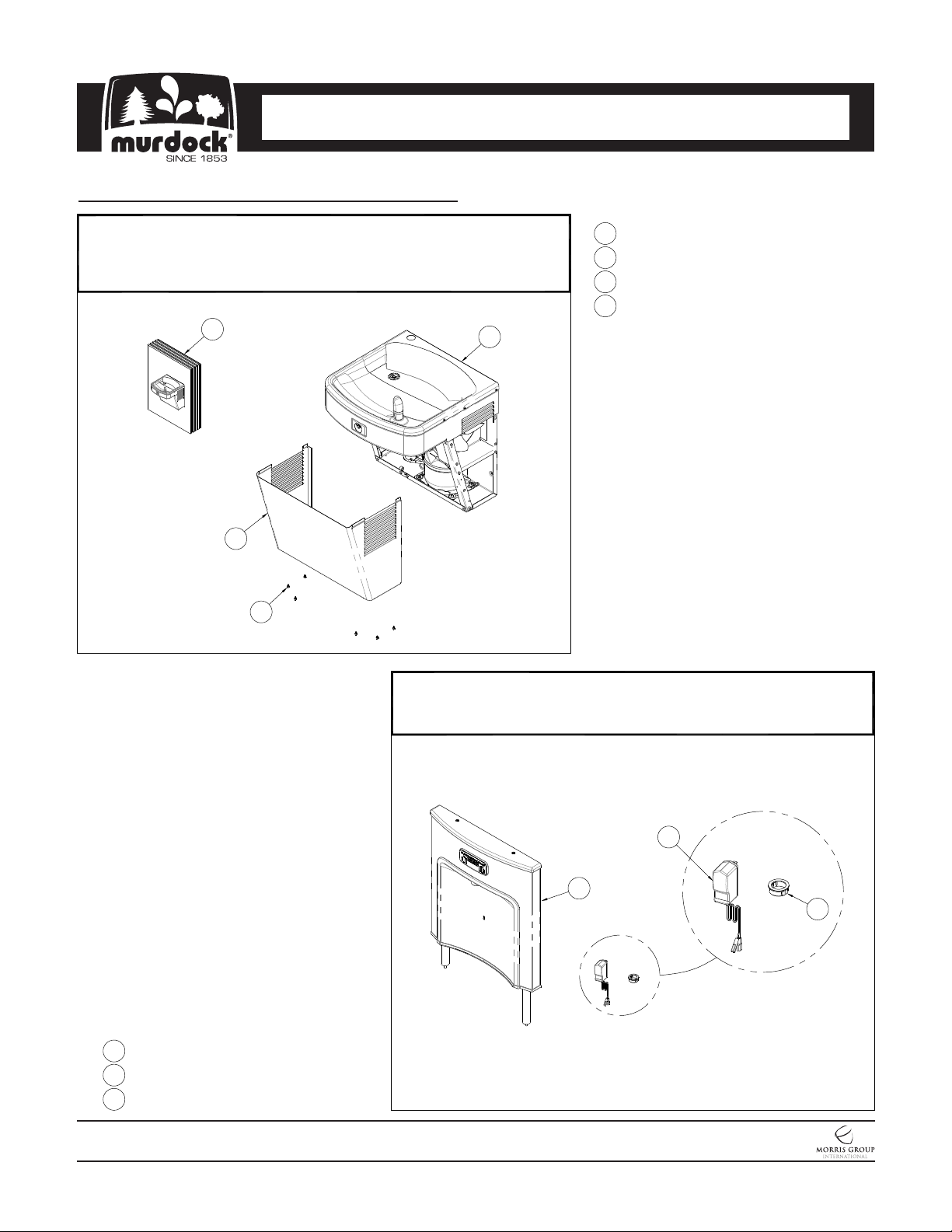
BF11/BF12 INSTALLATION INSTRUCTIONS
Install the newly obtained Water Cooler per the Installation Manual
1
provided with the unit. Do not install Access Panel at this time. Shut-off
water supply, then actuate Valve to relieve pressure. Place Screws and
Panel in secure location for further use in Manual.
4
2
3
1
1
Water Cooler Assembly
2
Access Panel
3
#8 x 3/8" Hex Washer Head Screw
4
Water Cooler Installation Manual
Remove Bottle Filler Assembly, Power Supply and Grommet from
2
packaging, careful to avoid damage to Fixture and Fixture Sub
Assemblies. Set Power Supply aside in a secure location.
1
1
Bottle Filler Assembly
2
Power Supply (Not provided with BF11)
3
Locking Grommet
MURDOCK MFG. • 15125 Proctor Avenue • City of Industry, CA 91746 USA
Phone 800-453-7465 or 626-333-2543 • Fax 626-855-4860 • www.murdockmfg.com
7020-956-001
Page 5 of 19
2
3
Member of
Revised: 12/11/18
Cooler Mounted Bottle Fillers
I N S TA L L AT I O N / M A I N T E N A N C E I N S T R U C T I O N S
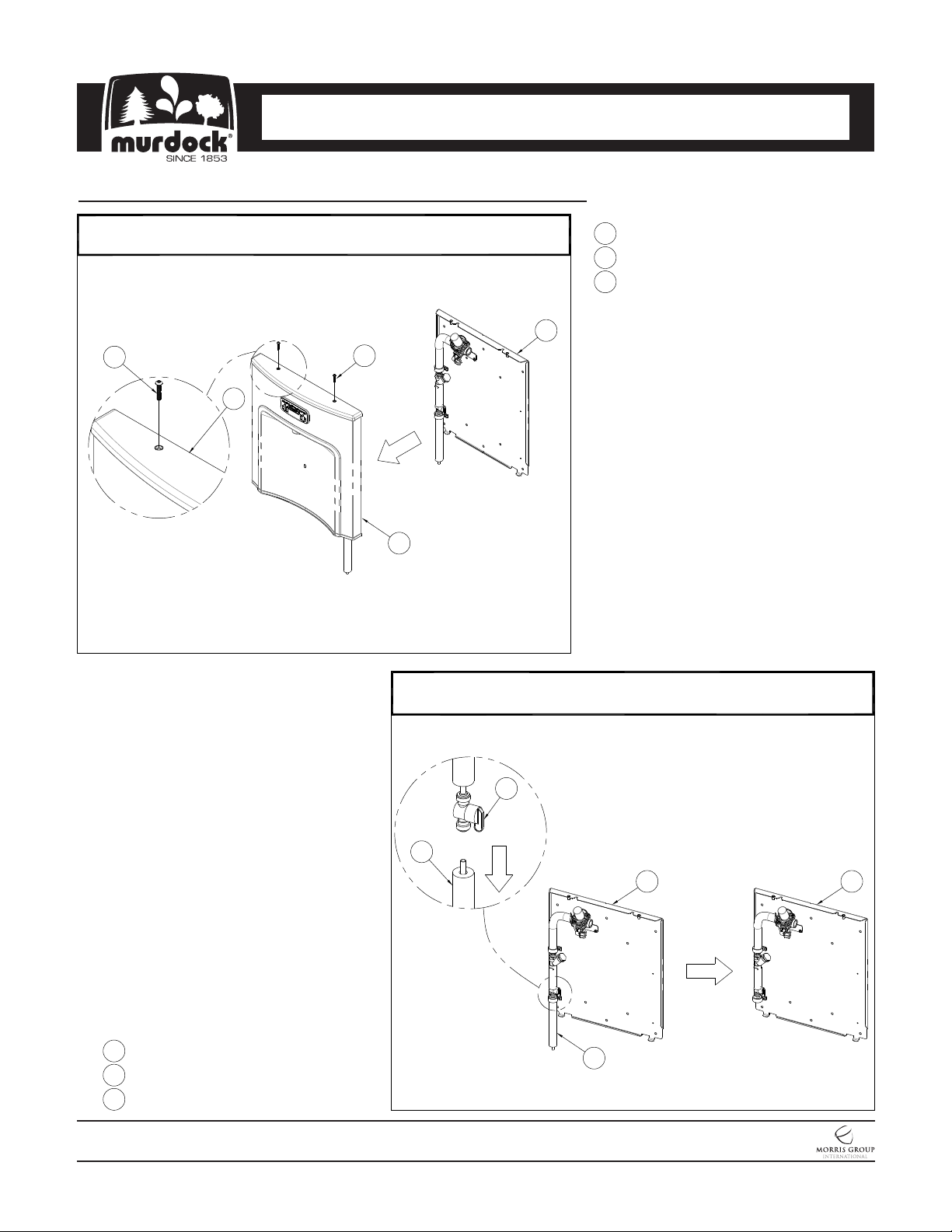
BF11/BF12 INSTALLATION INSTRUCTIONS (CONTINUED)
Unfasten Screws that hold the Bottle Filler Housing to the Mounting
3
Panel. Place Bottle Filler Panel and Screws in a secure location.
3
2
3
1
1
Bottle Filler Housing
2
Mounting Panel
3
#10-32 x 1" Button Head Screw
2
Disconnect the Water Supply Insulation and Tubing from 1/4" Shut-Off
4
Valve that is located on the Mounting Panel.
2
3
1
Mounting Panel
2
Shut-Off Valve
3
1/4" OD Tubing & Insulation
MURDOCK MFG. • 15125 Proctor Avenue • City of Industry, CA 91746 USA
Phone 800-453-7465 or 626-333-2543 • Fax 626-855-4860 • www.murdockmfg.com
7020-956-001
Page 6 of 19
3
1
Member of
Revised: 12/11/18
1
 Loading...