

Murdock A172-SO, A172100F-SO, A174100F-SO Maintance Manual
CONTEMPORARY WATER COOLERS
I N S TA L L AT I O N / M A I N T E N A N C E I N S T R U C T I O N S
I N S TA L L AT I O N / M A I N T E N A N C E I N S T R U C T I O N S
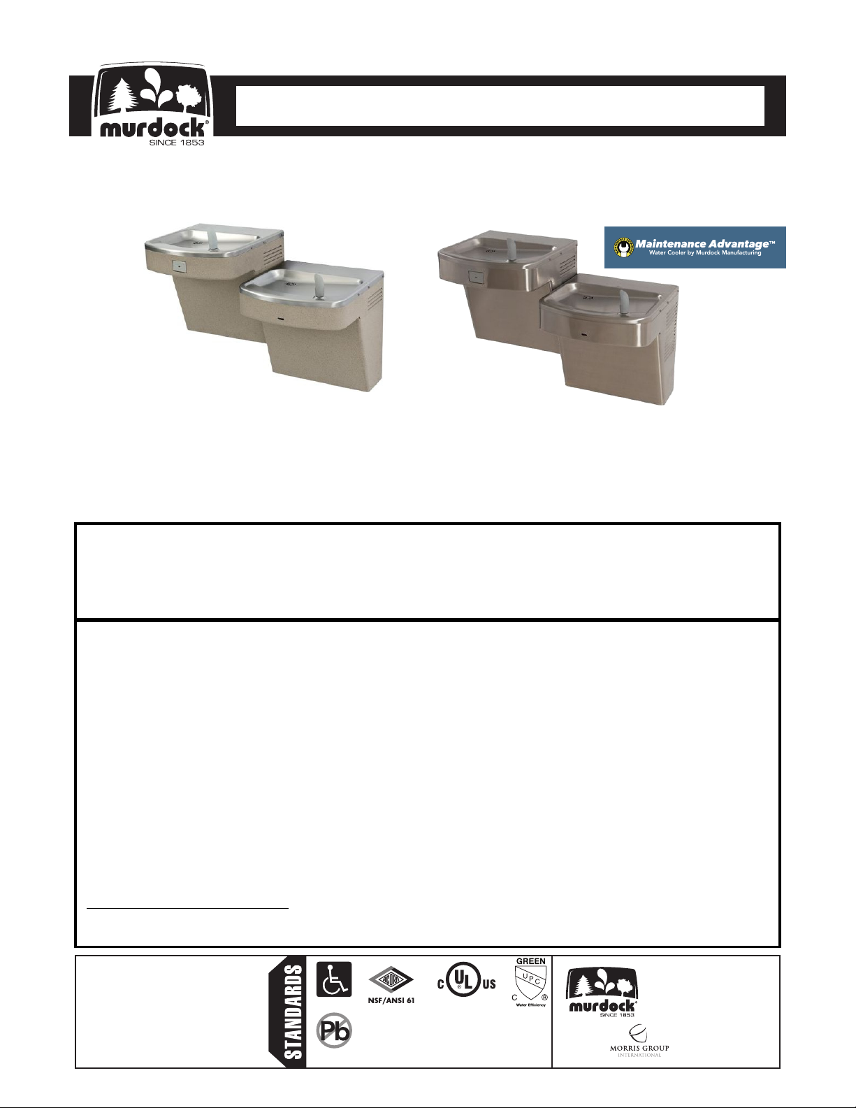
DRINKING FOUNTAIN
A172-SO Series
Barrier Free, Sensor Operated,
Wall Mounted Drinking Fountain
OR
A172100F-SO
A174100F-SO
TECHNICAL ASSISTANCE TOLL FREE TELEPHONE NUMBER:
1.800.591.9360
Technical Assistance Fax: 1.626.855.4894
NOTES TO INSTALLER:
1. Please leave this documentation with the owner of the fixture when finished.
2. Please read this entire booklet before beginning the installation.
3. Check your installation for compliance with plumbing, electrical and other applicable codes.
LIMITED WARRANTY - UNITED STATES & CANADA
Murdock warrants that its products are free from defects in material or workmanship under normal use and
service for a period of one year from date of original shipment or for 18 months after the date of shipment from the
factory, whichever comes first. Murdock’s liability under this warranty shall be discharged solely by replacement
or repair of defective material, provided Murdock is notified in writing within one year from date of shipment,
F.O.B. Industry, California.
This warranty does not cover installation or labor charges and does not apply to materials, which have been
damaged by other causes such as mishandling or improper care or abnormal use. The repair or replacement of the
defective materials shall constitute the sole remedy of the Buyer and the sole remedy of Murdock under this
warranty. Murdock shall not be liable under any circumstances for incidental, consequential or direct charges
caused by defects in the materials, or any delay in the repair or replacement thereof. This warranty is in lieu of all
other warranties expressed or implied. Product maintenance instructions are issued with each unit and disregard
or non-compliance with these instructions will constitute an abnormal use condition and void the warranty.
Stainless steel must be protected on job site during construction and must be properly maintained after the water
has been introduced into the water cooler or drinking fountain, or Murdock’s limited warranty is void.
LIMITED EXPORT WARRANTY - One year on parts only.
Murdock assumes no responsibility for use of void or
suspended data. © Copyright Murdock, City of
Industry, CA Member of Morris Group International.
Please visit www.murdockmfg.com for most
current specifications.
Federal
7020-961-001 Date: 12/20/17
COMPLIES WITH
Public Law
111-380
(No Lead)
Test rating conditions are
compliant with ARI 1010.
Member of
MURDOCK
15125 Proctor Ave.
City of Industry, CA
91746 U.S.A.
Phone 800-591-9360
626-336-4561
Fax 626-855-4894
www.murdockmfg.com
CONTEMPORARY WATER COOLERS
I N S TA L L AT I O N / M A I N T E N A N C E I N S T R U C T I O N S
I N S TA L L AT I O N / M A I N T E N A N C E I N S T R U C T I O N S
DRINKING FOUNTAIN
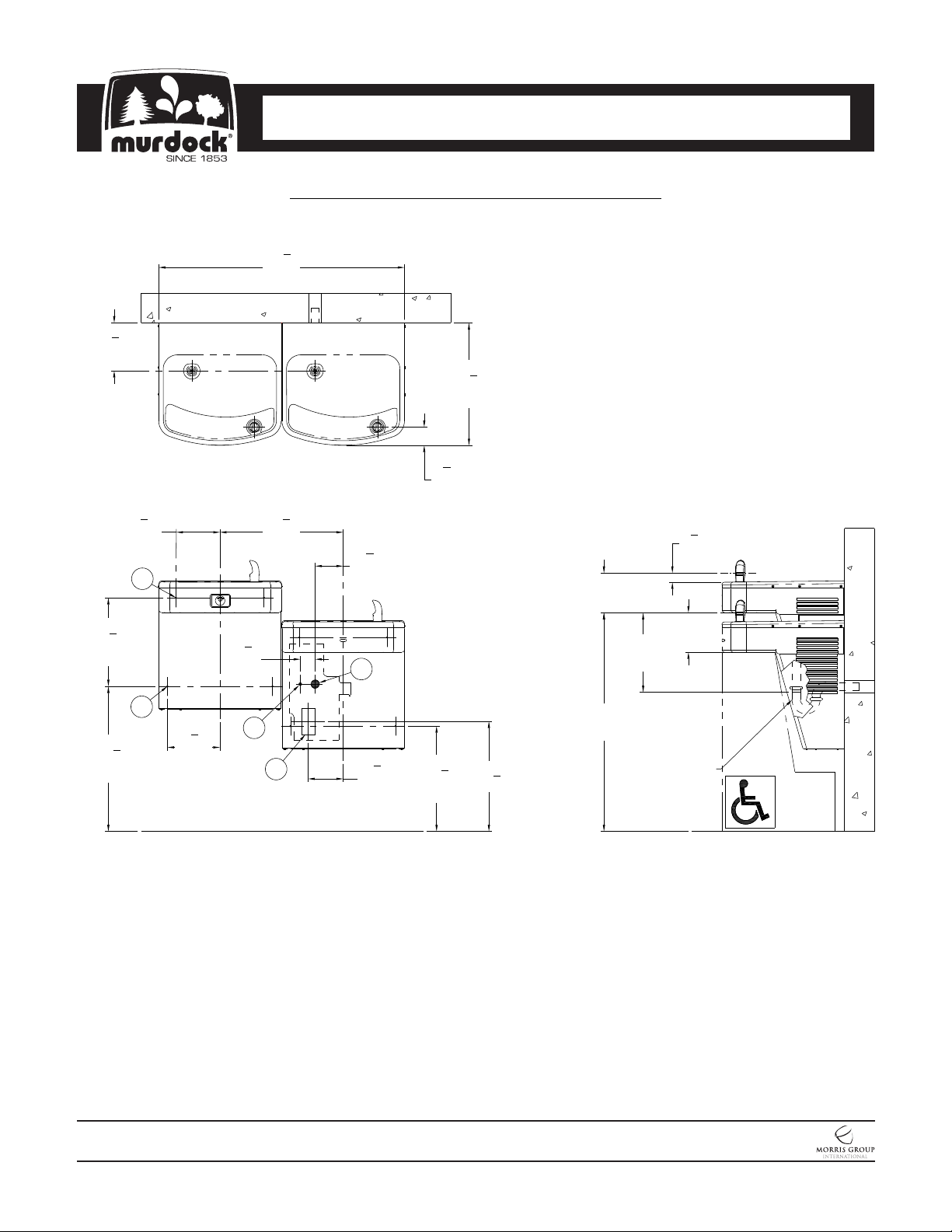
ROUGHING-IN AND DIMENSIONAL DRAWING
Prior to roughing consult with local, state, and federal codes for proper mounting height.
1
37
"
8
[943]
1
7
"
4
[184]
3
13
8
[340]
[168]
"
5
6
"
8
D
[57]
5
18
"
8
[473]
1
4
"
4
[108]
1
2
"
4
B
3
2
4
[70]
18
[470]
"
1
"
2
3
1
"
8
[35]
6"
[152]
6"
[152]
12"
[305]
*21
[556]
E
7
7
"
7
"
8
8
[200]
MOUNTING CONFIGURATION
A
C
AS SHIPPED
1
5
4
[133]
*15
[403]
7
8
5
"
*16
"
8
"
*33"
[838]
1-1/4" [32]
P-TRAP BY
OTHERS
General Notes:
1. All dimensions are in inches [MM]
2. Allow 4 inches [102 MM] minimum clearance per side for
ventilation
*3. Dimensions shown are for recommended adult height. Adjust
vertical dimensions as necessary to comply with Federal,
State, & Local Codes
4. Stop Valve, P-Trap & Electrical Outlet not supplied
5. Important: Units must be attached to wall with appropriate wall
Anchor Screws
NOTES:
are for ADA frontal approach installation. For Child ADA compliant parallel approach installation, decrease height of
installation for spout to be 30” maximum above finished floor. Provide clear floor space as required. Adjust vertical
dimensions as required to comply with federal, state, and local codes.
MURDOCK MFG. • 15125 Proctor Avenue • City of Industry, CA 91746 USA
Phone 800-453-7465 or 626-333-2543 • Fax 626-855-4860 • www.murdockmfg.com
7020-961-001
Page 2 of 10
Adjust vertical dimensions as required to comply with federal, state, and local codes. Dimensions indicated
A172-SO
A. 3/8" NCT Supply Inlet
B. Waste Outlet for 1-1/4" P-Trap, by others
C. Electrical Service Rough
D. Ø3/8" Hanger Bracket punching, 3 places
for Anchoring Hardware, by others
E. Ø1/4" punching, 2 places for Anchoring
Hardware, by others
Member of
Revised: 12/20/17
CONTEMPORARY WATER COOLERS
I N S TA L L AT I O N / M A I N T E N A N C E I N S T R U C T I O N S
I N S TA L L AT I O N / M A I N T E N A N C E I N S T R U C T I O N S
IMPORTANT:
1. Water supply is 3/8” Outside Diameter Copper Tube. Waste is 1-1/4” Outside Diameter.
2. Completely flush supply lines of all foreign debris before connecting to fixture. Drinking Fountain designed to not
affect taste, odor, color, or sediment. Optional water filter (WF1) is available should any of these problems arise
from the water supply.
3. Do NOT solder Copper Tube when inserted into the Coupler as damage to the O-Ring will result.
4. All burrs must be removed from outside of cut tubes before inserting into Coupler or other components.
5. WARNING: Warranty is voided if installation is not made following current Murdock Mfg. installation instructions
and if components are assembled to the fixture that is not approved by Murdock Mfg.
6. Fixture operates within water pressure range of 20 to 105 PSIG (138 to 724 kPa). Murdock Mfg. will not warranty
fixtures damaged when connected to supply lines with flow pressure lower than 20 PSIG (138 kPa) or higher than
105 PSIG (724 kPa). A pressure regulator must be furnished by others on supply line if inlet pressure is greater
than 105 PSIG (724 kPa).
7. Per UPC 609.10- All building water supply systems in which quick acting valves are installed shall be provided with
devices to absorb the hammer caused by high pressure resulting from the quick closing of the valve. These
pressure-absorbing devices shall be approved mechanical devices. Water pressure-absorbing devices will be
installed as close as possible to the quick closing valve.
INSTALLATION:
1. Mount Hanger Bracket to wall horizontally level as shown in Roughing-In and Dimensional Drawing. Note: Adjust
height of bracket if Bubbler outlet height is required to vary from that shown.
WARNING: Hanger Bracket MUST be securely anchored to wall with fasteners sufficient to support 3 times the
weight of Drinking Fountain. If wall can not provide adequate support, order and install optional fixture support
carrier.
2. Remove the Bottom Cover from the Drinking Fountain and set aside in a safe place. Save the Screws in a secure
location for re-use in later stages of installation.
Hang the Drinking Fountain on the Hanger Brackets ensuring the Bracket Tabs engage AND seat in the slots in the
3.
back of the Drinking Fountain. Verify Drinking Fountain are level, left to right AND front to back from bottom of unit.
NOTE: The Bubbler stream may be adversely affected if units are not square and level. Bottom of units and
Louvers should be used as reference to verify unit is square and plumb.
4. Anchor the Drinking Fountain to the wall at the lower mounting points in each Back Panel. Shim lower mounting
points to level unit if necessary.
5. Thoroughly flush the 3/8” O.D. supply line and then connect Drinking Fountain to Water Supply Angle Stop Valve (by
others) with supplied 3/8” O.D. Copper Tube.
6. Use supplied Flexible Hose and Clamps to connect Waste Tailpiece from the upper unit to the Waste Tailpiece of
lower unit and then make up 1-1/4” O.D. P-Trap Waste Connection. Waste P-Trap by others.
DRINKING FOUNTAIN
START UP:
1. Before connecting water supply and assembling Bottom Cover to Drinking Fountain, but after thoroughly flushing
the supply line and connecting it to the fixture, turn on building water supply and check all connections for leaks.
2. Air within the Drinking Fountain system or the structure supply piping will cause an irregular Bubbler outlet stream
until purged out by incoming water. Covering the Bubbler with a clean cup (or similar object) is recommended when
first activating Drinking Fountain to prevent excessive splashing. Depress the Pushbutton until steady water stream
is achieved.
3. If water flow requires adjustment, insert a Slotted Narrow Blade Screwdriver in the hole centered on the underside
of the fixture in the knee clearance area up to the Flow Regulator. Turning clockwise will increase flow and turning
counterclockwise will decrease flow.
4. Recheck all water and drain connections with water flowing through system.
5. Assemble Bottom Cover to Drinking Fountain with Screws furnished.
MURDOCK MFG. • 15125 Proctor Avenue • City of Industry, CA 91746 USA
Phone 800-453-7465 or 626-333-2543 • Fax 626-855-4860 • www.murdockmfg.com
7020-961-001
Page 3 of 10
A172-SO
Member of
Revised: 12/20/17
 Loading...