

Murdock A171, A171108F, A171408F, A171108S, A171408S Maintance Manual
...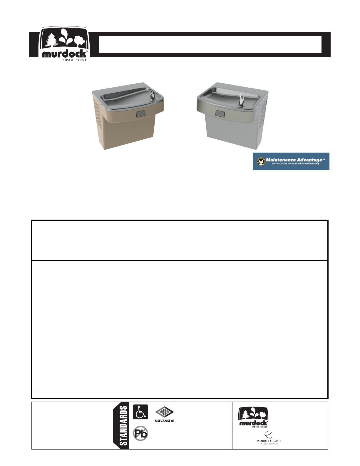
CONTEMPORARY WATER COOLERS
I N S TA L L AT I O N / M A I N T E N A N C E I N S T R U C T I O N S
I N S TA L L AT I O N / M A I N T E N A N C E I N S T R U C T I O N S
WATER COOLERS
A171.8 Series
Barrier Free, Wall Mounted Water Cooler
A171108F / A171408F / A171108S / A171408S
TECHNICAL ASSISTANCE TOLL FREE TELEPHONE NUMBER:
1.800.591.9360
Technical Assistance Fax: 1.626.855.4894
NOTES TO INSTALLER:
1. Please leave this documentation with the owner of the fixture when finished.
2. Please read this entire booklet before beginning the installation.
3. Check your installation for compliance with plumbing, electrical and other applicable codes.
Murdock warrants that every cooler, bottle filling station, packaged water chiller, fountain and accessory to be free
from defects in material and workmanship under normal use for one (1) year from date of install or eighteen (18)
months after the date of shipment from the factory, whichever comes first.
Murdock warrants the compressor and hermetically sealed refrigeration system, including cooling coil assembly
when part of the hermetically sealed refrigeration system, to be free from defects in material and workmanship
under normal use for an additional four (4) years from the end of the one (1) year period described above.
This warranty does not cover installation or labor charges and does not apply to materials, which have been
damaged by other causes such as mishandling or improper care or abnormal use. The repair or replacement of the
defective materials shall constitute the sole remedy of the Buyer and the sole remedy of Murdock under this
warranty. Murdock shall not be liable under any circumstances for incidental, consequential or direct charges
caused by defects in the materials, or any delay in the repair or replacement thereof. This warranty is in lieu of all
other warranties expressed or implied. Product maintenance instructions are issued with each unit and disregard
or non-compliance with these instructions will constitute an abnormal use condition and void the warranty.
Stainless steel must be protected on job site during construction and must be properly maintained after the water
has been introduced into the water cooler or drinking fountain, or Murdock’s limited warranty is void.
LIMITED WARRANTY - UNITED STATES & CANADA
LIMITED EXPORT WARRANTY - One year on parts only.
Murdock assumes no responsibility for use of void or
suspended data. © Copyright Murdock, City of
Industry, CA Member of Morris Group International.
Please visit www.murdockmfg.com for most
current specifications.
Federal
7020-904-001
Date: 09/07/18
COMPLIES WITH
Public Law
111-380
(No Lead)
Test rating conditions are
compliant with ARI 1010.
Member of
MURDOCK
15125 Proctor Ave.
City of Industry, CA
91746 U.S.A.
Phone 800-591-9360
626-336-4561
Fax 626-855-4894
www.murdockmfg.com
CONTEMPORARY WATER COOLERS
I N S TA L L AT I O N / M A I N T E N A N C E I N S T R U C T I O N S
I N S TA L L AT I O N / M A I N T E N A N C E I N S T R U C T I O N S
WATER COOLERS
IMPORTANT
This Fixture is intended for indoor use only and is not suitable for installation in an area where a water jet
could be used as well as in environments where freezing may occur. This fixture dispenses water that has
been lowered in temperature, but otherwise remains unchanged by the materials in the W ater Cooler. It is
common for electrical equipment to be grounded to water lines either within a structure or away from it.
Every attempt should be made to prevent this kind of grounding from generating electrical feedback into the
Water Cooler creating electrolysis. Electrolysis will cause a metallic taste or cause water metal content to
increase.
NOTICE
A Dielectric Coupling must be used to connect the Water Cooler to the water supply. A nonmetallic Coupler
is furnished with this Water Cooler to meet this requirement.
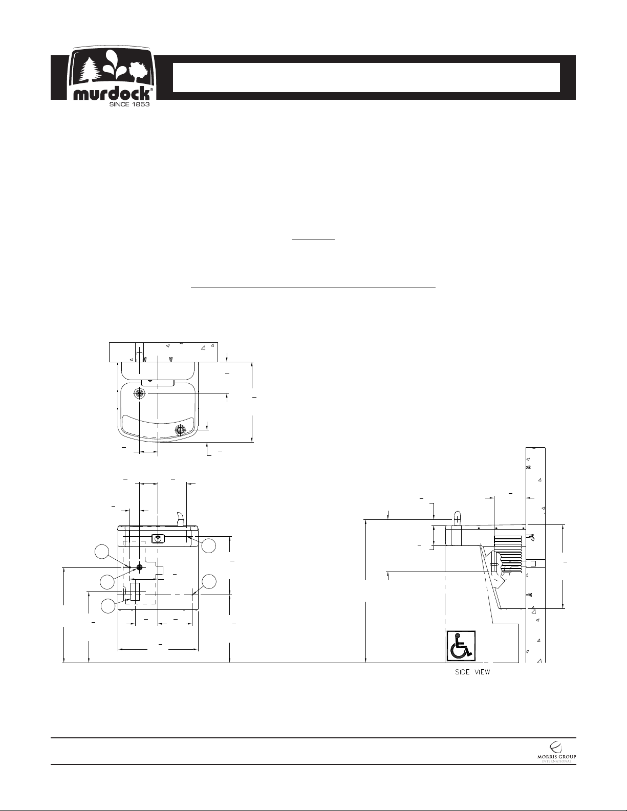
ROUGHING-IN AND DIMENSIONAL DRAWING
Prior to roughing-in, consult with local, state, and federal codes for proper mounting height. All installation
and service may only be performed by authorized personnel. No unauthorized persons shall have access to
the service area.
General Notes:
1. All Dimensions are in Inches [MM]
2. Allow 4 inches [102 MM] minimum clearance per side for ventilation
3. Dimensions shown are for ADA adult height. Adjust vertical dimensions
1
"
2
as necessary to comply with Federal, State, & Local Codes
4. Stop Valve, P-Trap, & Electrical Outlet not supplied
5. Important: Water Coolers must be attached to wall with appropriate
Anchor Screws
A. 3/8" OD Supply Inlet
B. Waste Outlet for 1-1/4" P-Trap by others
C. Electrical Service Rough-In
D. Ø3/8" Hanger Bracket punching, 3 places
for Anchoring Hardware by others
E. Ø1/4" punching, 2 places for Anchoring
Hardware by others
12"
[305]
TAIL
PIECE
*33"
[838]
3
1
8
[35]
5
4
8
[117]
"
"
1
7
4
[184]
"
19
[492]
*22"
[559]
*16
[416]
1
7
"
4
[184]
18
[470]
1
4
"
4
[108]
1
4
"
4
[108]
1
2
"
4
[57]
A
B
C
3
"
8
5
[133]
1
"
4
[470]
18
[168]
1
"
2
5
6
8
1
6
2
[165]
7
7
8
[200]
"
"
"
3
2
"
4
[70]
D
1
13
"
2
[343]
E
5
*15
"
8
[397]
3
"
8
NOTES: Dimensions indicated (*) are for ADA frontal approach installation. Adjust vertical dimension (*)
as required to comply with federal, state, and local codes. For Child ADA compliant parallel approach,
decrease Bubbler spout height to 30” maximum above finished floor. Provide clear floor space as
required.
MURDOCK MFG. • 15125 Proctor Avenue • City of Industry, CA 91746 USA
Phone 800-453-7465 or 626-333-2543 • Fax 626-855-4860 • www.murdockmfg.com
7020-904-001
Page 2 of 13
A171.8
Member of
Revised: 09/07/18
CONTEMPORARY WATER COOLERS
I N S TA L L AT I O N / M A I N T E N A N C E I N S T R U C T I O N S
I N S TA L L AT I O N / M A I N T E N A N C E I N S T R U C T I O N S
WATER COOLERS
PRIOR TO INSTALLATION:
Important: Some options may slightly alter installation. To ensure proper installation, review the Manual
thoroughly and verify rough-ins before beginning work. Leave this Manual with the owner or
maintenance personnel upon completion of installation.
— Fixture mounting requirements: Industry standard wall construction, adequate to support the fixture
and installer-provided Wall Anchors sufficient to secure the fixture.
— Receptacle(s) must be wired to a GFCI protected circuit. Fixture must be earth grounded per NEC
(National Electric Code).
— Inspect fixture and all parts for damage.
—To avoid a hazard due to instability, fixture must be installed in accordance with the instructions.
IMPORTANT:
1. Waste P-Trap, Water Supply Service Angle Stop Valve, and 2” x 4” Electrical Plug-In Receptacle to
be supplied by others in accordance with local codes. A metallic P-Trap (by others) must be used for
the Drain connection.
2. Provide 4” minimum clear space on fixture sides to allow for proper ventilation through Cabinet
Louvers.
3. Water Supply Inlet is 3/8” Outer Diameter copper Tubing. Waste Outlet is 1-1/4” Outer Diameter.
4. Completely flush supply lines of all foreign debris before connecting to fixture. Water Cooler is
designed to not cause problems with taste, odor, color, or sediment. Optional (-WF1) Water Filter is
available should any of these problems arise from the Water Supply.
5. Do NOT solder Tubing inserted into the Coupler as damage to the O-Ring may result.
6. All burrs must be removed from outside of cut Tubing before inserting into Coupler or other
components.
7. Power Supply must be identical in voltage, cycle and phase to that specified on the Water Cooler
Data Plate. Electrical Outlet and furnished Power Cord with Plug must be used to supply power to
fixture. Do NOT wire Compressor directly to the Power Supply.
8. This unit must be grounded per the requirements of applicable electrical codes.
9. Warranty is voided if installation is not followed per current Murdock Mfg. installation instructions
and if components are assembled to the fixture that are not approved by Murdock Mfg.
10. Fixture is to operate within a water pressure range of 25 PSIG (172 kPa) to 105 PSIG (724 kPa).
Warranty is void if the unit is allowed to operate outside the range of 25 PSIG (172 kPa) to 105
PSIG (724 kPa). A Pressure Regulator must be installed by others on supply line if inlet pressure is
greater than 105 PSIG (724 kPa).
11. Due to cold waste water, Murdock Mfg. recommends that P-Trap supplied by installer be insulated
to prevent excessive condensation.
12. 609.10 Water Hammer. Building water supply systems where quick-acting valves are installed shall
be provided with water hammer arrester(s) to absorb high pressures resulting from the quick closing
of these valves. Water hammer arresters shall be approved mechanical devices that comply with
ASSE 1010 or PDI-WH 201 and shall be installed as close as possible to quick-acting valves.
MURDOCK MFG. • 15125 Proctor Avenue • City of Industry, CA 91746 USA
Phone 800-453-7465 or 626-333-2543 • Fax 626-855-4860 • www.murdockmfg.com
7020-904-001
Page 3 of 13
A171.8
Member of
Revised: 09/07/18
CONTEMPORARY WATER COOLERS
I N S TA L L AT I O N / M A I N T E N A N C E I N S T R U C T I O N S
I N S TA L L AT I O N / M A I N T E N A N C E I N S T R U C T I O N S
WATER COOLERS
13. 609.10.1 Mechanical Devices. Where listed mechanical devices are used, the manufacturer’s
specifications as to location and method of installation shall be followed.
14. For optimum performance, the fixture is to operate within the ambient temperature range of 41°F
(5°C) to 111°F (44°C).
15. If the Power Supply Cord is damaged, it may only be replaced by authorized qualified persons.
INSTALLATION:
1. Mount Hanger Bracket to wall horizontally level as shown in Roughing-In and Dimensional Drawing.
Note: Adjust height of Bracket if Bubbler outlet height is required to vary from that shown/indicated
.Hanger Bracket MUST be securely anchored to wall with fasteners sufficient to support 3 times the
weight of Water Cooler. If wall cannot provide adequate support, order and install optional fixture
support carrier.
2. Remove the Bottom Cover from the Water Cooler and set aside in a safe place. Place the Screws
in a secure location for re-use in later stages of installation.
3. Hang the Water Cooler on the Hanger Bracket, ensuring the Bracket Tabs engage AND seat in the
slots in the back of the Water Cooler. Verify Water Cooler is level, left to right AND front to back from
bottom of unit. NOTE: The Bubbler stream may be adversely affected if unit is not square and level.
Bottom of unit and Louvers should be used as reference to verify unit is square and plumb.
4. Anchor Water Cooler to wall at other mounting points in Base. Shim lower rear mounting points to
level unit, if necessary.
5. Thoroughly flush the 3/8” O.D. supply line and then connect Water Cooler to water supply Angle
Stop Valve (by others) with supplied 3/8” O.D. copper Tubing.
6. Make up 1-1/4” O.D. P-Trap (by others) waste connection.
START UP:
1. Before connecting Power Supply and assembling Bottom Cover to Water Cooler, but after
thoroughly flushing the supply line and connecting it to the fixture, turn on building water supply and
check all connections for leaks.
2. Air within the Water Cooler system or the structure supply piping will cause an irregular Bubbler
outlet stream until purged out by incoming water. Covering the Bubbler with a clean cup (or similar
object) is recommended when first activating Water Cooler to prevent excessive splashing. Depress
the Pushbutton until steady water stream is achieved.
3. If water flow requires adjustment, insert a slotted narrow blade Screwdriver through the hole
centered on the Pushbutton to the Flow Regulator. Turning clockwise will increase flow and turning
counterclockwise will decrease flow.
4. Recheck all water and drain connections with water flowing through system.
5. With power still NOT connected, carefully rotate Cooling Fan manually to insure proper clearance
and free Fan action.
6. Plug Water Cooler into Electrical Outlet and make sure unit begins to function.
7. Assemble Bottom Cover to Water Cooler with Screws furnished.
MURDOCK MFG. • 15125 Proctor Avenue • City of Industry, CA 91746 USA
Phone 800-453-7465 or 626-333-2543 • Fax 626-855-4860 • www.murdockmfg.com
7020-904-001
Page 4 of 13
A171.8
Member of
Revised: 09/07/18
 Loading...