

Murdock A152400F-BF4, A152400S-BF4, A152/FG-BF4, A152400F-FG-BF4, A152400S-FG-BF4 Maintance Manual
CONTEMPORARY WATER COOLERS
I N S TA L L AT I O N / M A I N T E N A N C E I N S T R U C T I O N S
I N S TA L L AT I O N / M A I N T E N A N C E I N S T R U C T I O N S
DRINKING FOUNTAINS
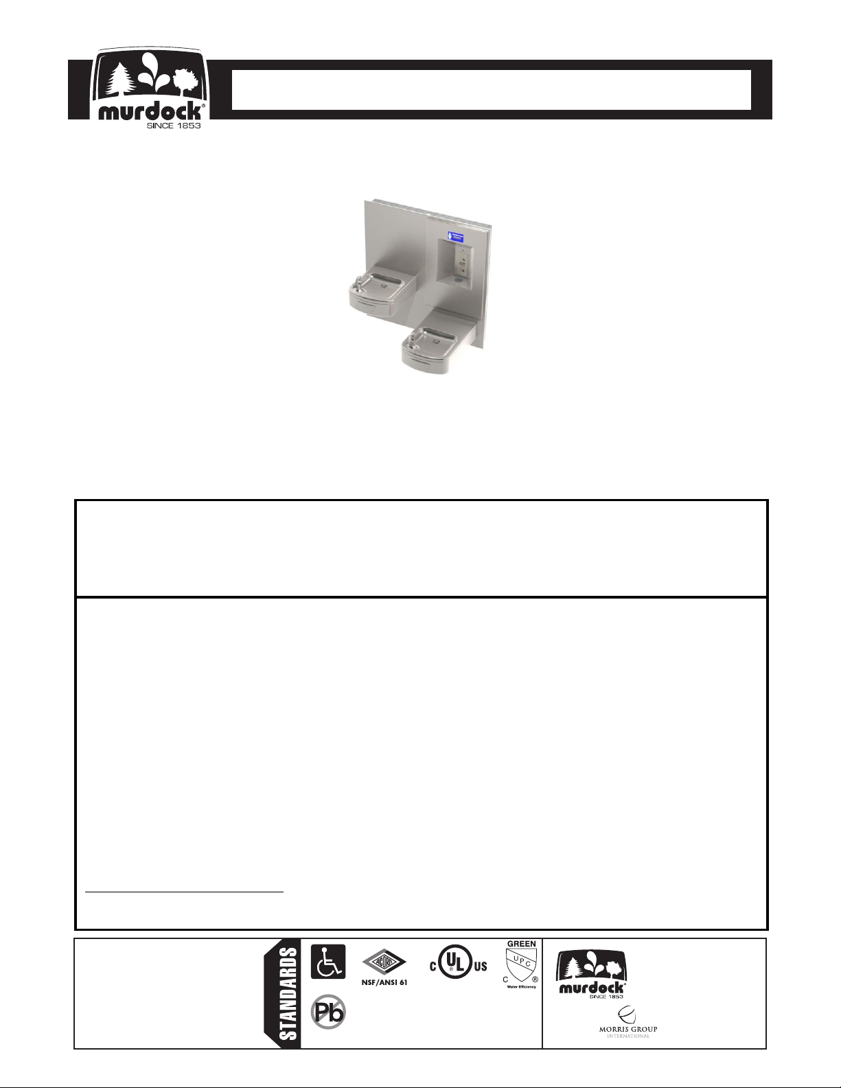
A152/FG-BF4 Series
Rounded Box Barrier-Free Wall Mount Bi-Level Drinking
Fountain with Sensor Activated Bottle Filler
** U.S. DESIGN PATENT D545,607 (Bowl Design)
A152400F-BF4 / A152400S-BF4 / A152400F-FG-BF4 / A152400S-FG-BF4
TECHNICAL ASSISTANCE TOLL FREE TELEPHONE NUMBER:
1.800.591.9360
Technical Assistance Fax: 1.626.855.4894
NOTES TO INSTALLER:
1. Please leave this documentation with the owner of the fixture when finished.
2. Please read this entire booklet before beginning the installation.
3. Check your installation for compliance with plumbing, electrical and other applicable codes.
LIMITED WARRANTY - UNITED STATES & CANADA
Murdock warrants that its products are free from defects in material or workmanship under normal use and
service for a period of one year from date of install or for 18 months after the date of shipment from the factory,
whichever comes first. Murdock’s liability under this warranty shall be discharged solely by replacement or repair
of defective material, provided Murdock is notified in writing within one year from date of shipment, F.O.B.
Industry, California.
This warranty does not cover installation or labor charges and does not apply to materials, which have been
damaged by other causes such as mishandling or improper care or abnormal use. The repair or replacement of the
defective materials shall constitute the sole remedy of the Buyer and the sole remedy of Murdock under this
warranty. Murdock shall not be liable under any circumstances for incidental, consequential or direct charges
caused by defects in the materials, or any delay in the repair or replacement thereof. This warranty is in lieu of all
other warranties expressed or implied. Product maintenance instructions are issued with each unit and disregard
or non-compliance with these instructions will constitute an abnormal use condition and void the warranty.
Stainless steel must be protected on job site during construction and must be properly maintained after the water
has been introduced into the water cooler or drinking fountain, or Murdock’s limited warranty is void.
LIMITED EXPORT WARRANTY - One year on parts only.
Murdock assumes no responsibility for use of void or
suspended data. © Copyright Murdock, City of
Industry, CA Member of Morris Group International.
Please visit www.murdockmfg.com for most
current specifications.
7020-951-001 Date: 02/02/18
COMPLIES WITH
Federal
Public Law
111-380
(No Lead)
Test rating conditions are
compliant with ARI 1010.
Member of
MURDOCK
15125 Proctor Ave.
City of Industry, CA
91746 U.S.A.
Phone 800-591-9360
626-336-4561
Fax 626-855-4894
www.murdockmfg.com
CONTEMPORARY WATER COOLERS
I N S TA L L AT I O N / M A I N T E N A N C E I N S T R U C T I O N S
I N S TA L L AT I O N / M A I N T E N A N C E I N S T R U C T I O N S
This fixture is intended to dispense water that has been lowered in temperature, but otherwise remains
unchanged by the materials in the drinking fountain. It is common for electrical equipment to be grounded to
water lines either within a structure or away from it. Every attempt should be made to prevent this kind of
grounding from generating electrical feedback into the drinking fountain creating electrolysis. Electrolysis will
cause a metallic taste or cause water metal content to increase.
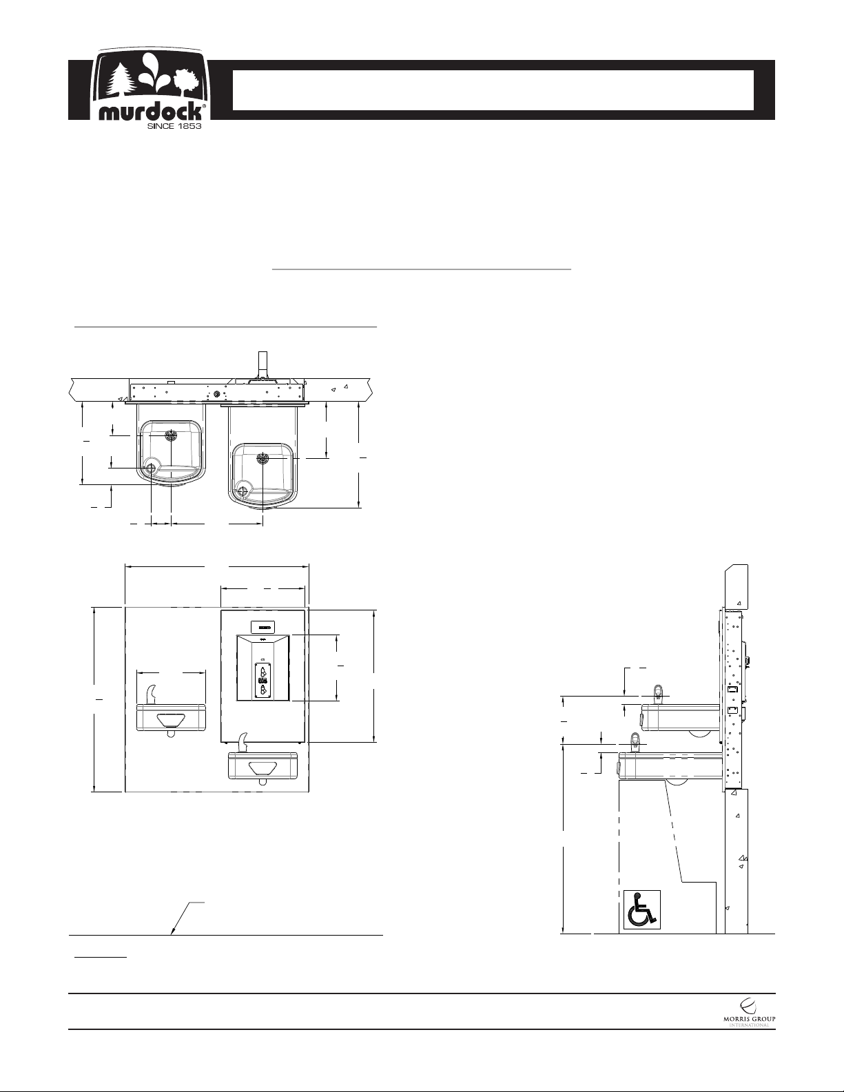
ROUGHING-IN AND DIMENSIONAL DRAWING
Prior to roughing in, consult with local, state, and federal codes for proper mounting height.
A152/FG-BF4 Wall Mounted Drinking Fountain
Note: There are no mounting changes to be made for -SO models.
DRINKING FOUNTAINS
IMPORTANT
14
5
8
2
32
6"
"
10"
18
5
"
8
General Notes:
1. All dimensions are in inches
*2. Dimensions shown are for recommended adult
height. Adjust vertical dimensions as necessary
to comply with federal, state, & local codes.
7
"
8
1
"
2
12"
1
"
4
16"3
32"
14
3
"
4
11
1
"
2
23"
3
8
"
8
3
1
"
8
3
1
"
8
*33"
Finished
Floor
NOTES: Dimensions shown for Adult ADA compliant installation. For Child ADA compliant parallel approach
installation, decrease height of installation by 3 inches. Provide clear floor space as required. Adjust vertical
dimensions as required to comply with federal, state, and local codes.
MURDOCK MFG. • 15125 Proctor Avenue • City of Industry, CA 91746 USA
Phone 800-453-7465 or 626-333-2543 • Fax 626-855-4860 • www.murdockmfg.com
7020-951-001
Page 2 of 22
A152-BF4
Member of
Revised: 02/02/18
CONTEMPORARY WATER COOLERS
I N S TA L L AT I O N / M A I N T E N A N C E I N S T R U C T I O N S
I N S TA L L AT I O N / M A I N T E N A N C E I N S T R U C T I O N S
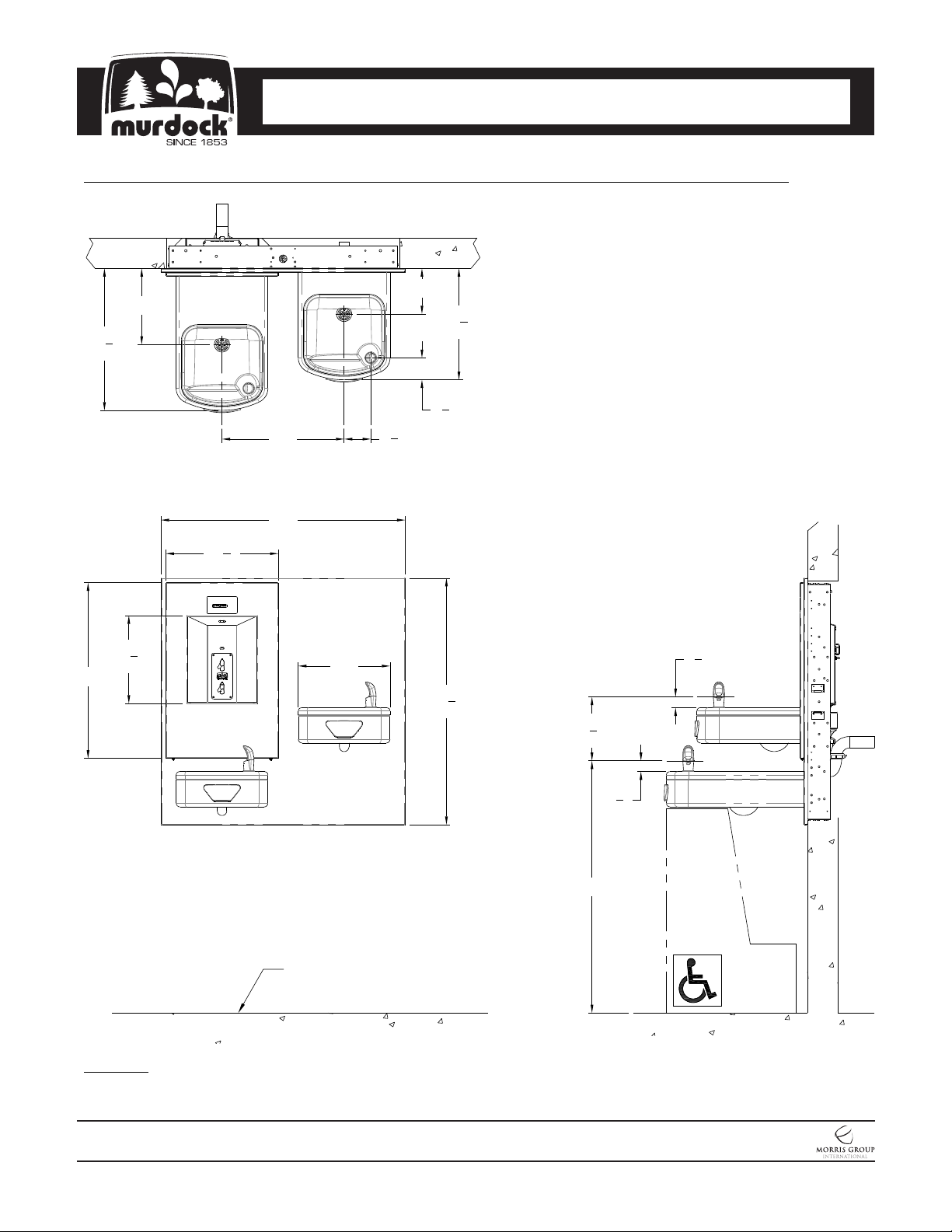
A152-RBL-BF4 Refrigerated Reverse Bi-Level Wall Mounted Drinking Fountain with Bottle Filler
10"
5
18
"
8
16" 3
32"
3
14
"
4
DRINKING FOUNTAINS
6"
5
14
"
8
7
2
"
1
2
8
"
General Notes:
1. All dimensions are in inches
*2. Dimensions shown are for recommended adult
height. adjust vertical dimensions as necessary
to comply with federal, state, & local codes.
23"
11
1
"
2
12"
FINISHED
FLOOR
32
1
"
4
3
8
8
*33"
"
3
1
"
8
3
1
"
8
NOTES: Dimensions shown for Adult ADA compliant installation. For Child ADA compliant parallel
approach installation, decrease height of installation by 3 inches. Provide clear floor space as required.
Adjust vertical dimensions as required to comply with federal, state, and local codes.
MURDOCK MFG. • 15125 Proctor Avenue • City of Industry, CA 91746 USA
Phone 800-453-7465 or 626-333-2543 • Fax 626-855-4860 • www.murdockmfg.com
7020-951-001
Page 3 of 22
A152-BF4
Member of
Revised: 02/02/18
CONTEMPORARY WATER COOLERS
I N S TA L L AT I O N / M A I N T E N A N C E I N S T R U C T I O N S
I N S TA L L AT I O N / M A I N T E N A N C E I N S T R U C T I O N S
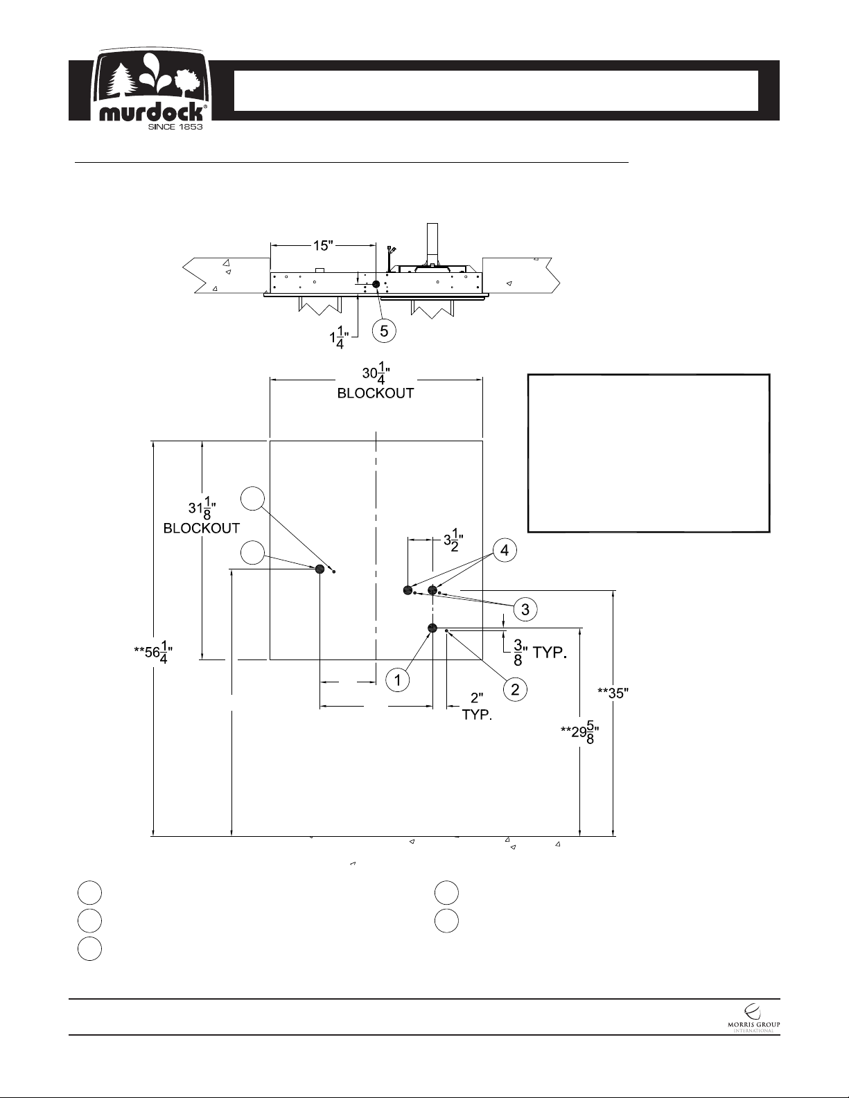
A152/FG-BF4 Refrigerated Wall Mounted Drinking Fountain Inlet & Outlet Rough-Ins
Note: There are no mounting changes to be made for -SO models.
2
DRINKING FOUNTAINS
General Notes:
1. Dimension indicated with (**) is
C
L
for 33" drinking fountain
discharge height. if discharge
height differs, adjust accordingly.
2. Standard Bi-Level rough-ins
shown. For -RBL Reverse
Bi-Level, -RBL Mounting Frame
rough-ins opposite.
1
**38"
1-1/4" O.D. Drinking Fountain Waste Outlet
1
3/8" NCT Drinking Fountain Supply Inlet
Alternate 3/8" NCT Bottle Filler Supply Inlets
3
8"
16"
Alternate 1-1/4" O.D. Bottle Filler Waste Outlet
4
Electrical Service Rough2
5
MURDOCK MFG. • 15125 Proctor Avenue • City of Industry, CA 91746 USA
Phone 800-453-7465 or 626-333-2543 • Fax 626-855-4860 • www.murdockmfg.com
7020-951-001
Page 4 of 22
A152-BF4
Member of
Revised: 02/02/18
CONTEMPORARY WATER COOLERS
I N S TA L L AT I O N / M A I N T E N A N C E I N S T R U C T I O N S
I N S TA L L AT I O N / M A I N T E N A N C E I N S T R U C T I O N S
Prior to roughing in, consult with local, state, and federal codes for proper mounting height.
Notes:
1-Standard Bi-Level rough-ins shown. For -RBL Reverse Bi-Level, -RBL
Mounting Frame rough-ins opposite
DRINKING FOUNTAINS
DIMENSIONAL DRAWING
1
2
30
16"
1
"
4
Finished
Floor
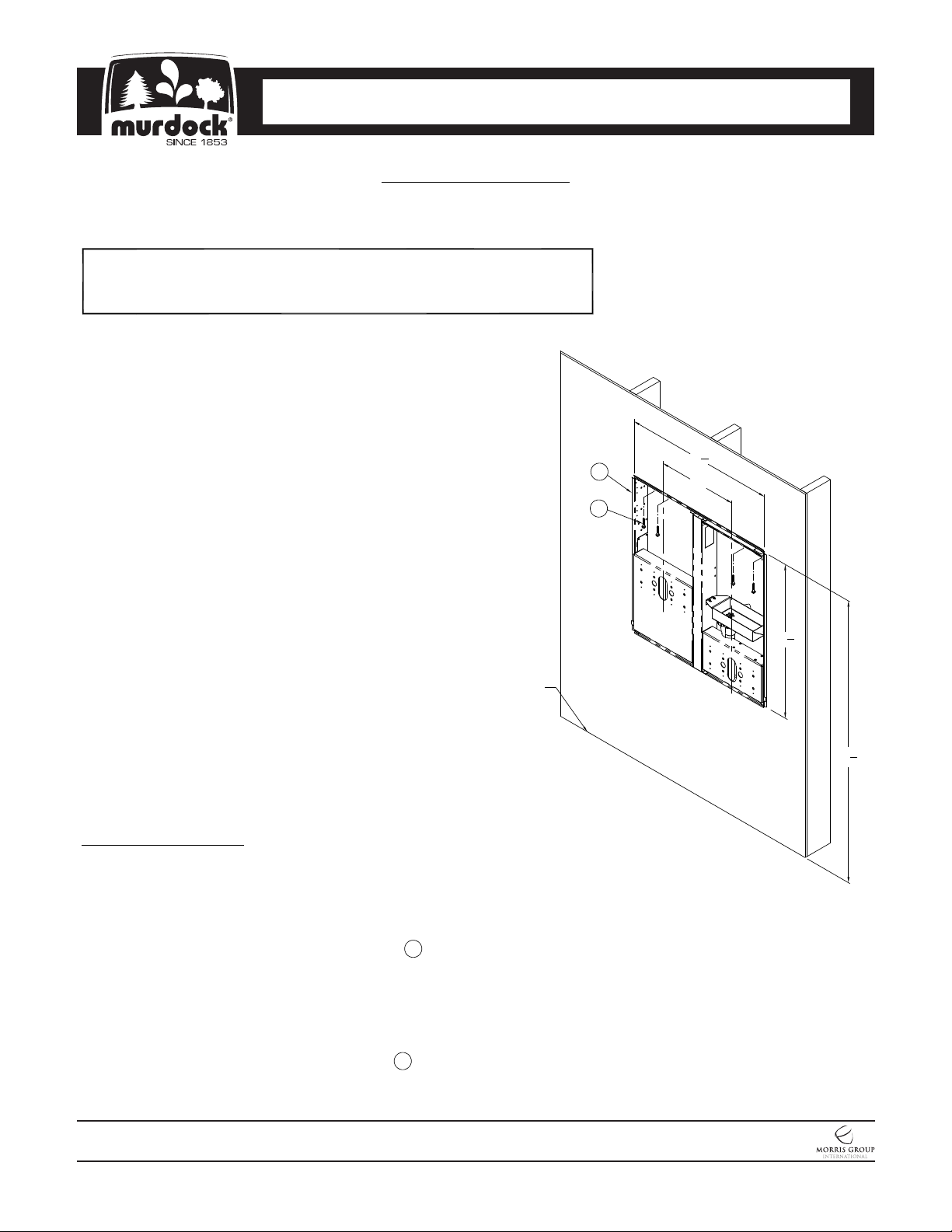
Installation Instructions:
A- Provide 30-1/4" wide x 31-1/8" tall wall opening at
appropriate height. Provide structure support around
inside of the opening for frame anchoring.
B- Carefully remove Bi-Level Mounting Frame 1 , and
panel from packaging, preventing damage.
C- Center frame within wall opening with side, top, and
bottom lips overlapping outside the opening and up
against finished wall face. Secure to wall through
the sides, top and bottom using hardware 2 by
others ensuring 16" centerline dimension
left-to-right.
MURDOCK MFG. • 15125 Proctor Avenue • City of Industry, CA 91746 USA
Phone 800-453-7465 or 626-333-2543 • Fax 626-855-4860 • www.murdockmfg.com
7020-951-001
Page 5 of 22
A152-BF4
1
31
"
8
1
56
"
4
Member of
Revised: 02/02/18

CONTEMPORARY WATER COOLERS
I N S TA L L AT I O N / M A I N T E N A N C E I N S T R U C T I O N S
I N S TA L L AT I O N / M A I N T E N A N C E I N S T R U C T I O N S
IMPORTANT:
1. Water Supply Service Stop Valve, Water Connections and Electrical Connections to be supplied by others in
accordance with local codes.
2. Waste is 1-1/4” Outer Diameter. Drinking Fountain water inlet is 3/8” Outer Diameter copper tube. Bottle
Filler water inlet is 3/8” Outer Diameter copper tube. Water line by others.
3. Completely flush supply lines of all foreign debris before connecting to fixture. Optional Water Filter (WF1), is
available should any problems with taste, odor, color, or sediment arise from the water supply.
4. Do NOT solder tubes inserted into the bottle filler or the fountain strainer as damage to the o-rings on the
push-in fittings may result.
5. All burrs must be removed from outside of cut tubes before inserting into strainer or other components.
6. Provide electrical service to J-Box to power sensor and solenoid valve.
7. This unit must be grounded per the requirements of applicable electrical codes.
8. Fixture operates within water pressure range of 174 kPa (25 psig) to 724 kPa (105 psig). Murdock Mfg. will
not warranty chiller damaged when connected to supply lines with flow pressure lower that 174 kPa (25 psig)
or higher than 724 kPa (105 psig). A pressure regulator must be furnished by others on supply line if inlet
pressure is greater than 724 kPa (105 psig).
9. Per UPC 609.10-All building water supply systems in which quick acting valves are installed shall be
provided with devices to absorb the hammer caused by high pressure resulting from the quick closing of the
valve. These pressure-absorbing devices shall be approved mechanical devices. Water pressure-absorbing
devices shall be installed as close as possible to the quick closing valve.
PRIOR TO INSTALLATION:
1. Read all installation instructions carefully, before proceeding.
2. Carefully remove all fixture components from packaging, preventing scratching or damage. Inspect fixture
and all parts from damages and all parts that are bolted on.
3. Provide mounting surface, adequate to support the fixture and loads on the fixture.
4. Provide rough-ins as shown on the roughing-in and dimensional drawing, including water supply, drain pipe
and gravel drain well. (See rough-in details)
5. Electrical Receptacle(s) must be wired to a GFCI protected circuit. Fixture must be earth grounded per NEC
(National Electrical Code).
6. Completely flush water supply lines of all foreign debris, before connecting to the fixture.
DRINKING FOUNTAINS
A152-BF4 SERIES DRINKING FOUNTAIN INSTALLATION:
1. Insert Mounting Frame into the Rough-In Block Out and secure using 1/4”-20 UNC Mounting Hardware
(Provided by Others).
2. Hang Trim Panel on Mounting Frame. Note: The included 1” brackets do not get used with this installation
and the Plastic Spacers are typically not required and can be discarded.
3. Install the eight (8) Threaded Studs into the Wall Mounting Frame.
4. Remove the Drinking Fountain Top by unfastening the Drain Screw and lifting at the front while pulling
forward. Disconnect Tubing from Bubblers by unfastening Ferrule Nuts. Set Top aside in a safe place where
it will not be damaged. Place the Drain Screw in a secure location where it will not be lost.
5. Align Fixture Mounting Points with Studs and slide Fixture to finished wall. Anchor with Nuts and Washers
provided.
6. Assemble P-Trap to Drain Adapter and then Assemble to unit with Phillips Head Screws.
7. Make-up 1-1/4” outer diameter Waste Connection.
8. After thoroughly flushing the 3/8” outer diameter supply line, connect water supply to the 3-Way Divider
Assembly. From the 3-Way Divider Assembly, connect to 1/4” Nominal Copper Tube Inlets, Stops on
Supplies recommended. See Water Tubing Connections for visual.
9. Reconnect 1/4” OD Polyethylene Tube to Bubbler with Ferrule Nuts.
10. Test operation of Bubblers by depressing buttons and adjust the flow rate as required, see Water Tubing
connections for detail. Check all connections and Waste Piping for leaks. Correct if present.
11. Set Drain Gasket on Drain Adapter.
12. Re-install tops to unit by engaging the back clip and securing with Drain Screw.
MURDOCK MFG. • 15125 Proctor Avenue • City of Industry, CA 91746 USA
Phone 800-453-7465 or 626-333-2543 • Fax 626-855-4860 • www.murdockmfg.com
7020-951-001
Page 6 of 22
A152-BF4
Member of
Revised: 02/02/18
CONTEMPORARY WATER COOLERS
I N S TA L L AT I O N / M A I N T E N A N C E I N S T R U C T I O N S
I N S TA L L AT I O N / M A I N T E N A N C E I N S T R U C T I O N S
A152FG-BF4 DRINKING FOUNTAIN INSTALLATION:
1. Insert mounting frame into the rough-in block out and secure using 1/4”-20 UNC mounting hardware
(Provided by Others).
2. Hang Trim Panel on Mounting Frame. Note: The included 1” brackets do not get used with this installation
and the plastic spacers are typically not required and can be discarded.
3. Install the eight (8) threaded studs into the Wall Mounting Frame
4. Carefully remove Drinking Fountain Fixtures from packaging material and Bottom Access Panel to prevent
scratching or damage.
5. Inspect Fixture Housing to ensure all Tubing connections, Bubblers and Pushbuttons have not become loose
during shipping. Correct if necessary.
5. Align Fixture Mounting Points with Studs and slide Fixture to finished wall. Anchor with Nuts and Washers
provided.
6. Assemble P-Trap to Drain Adapter. Position Drain Gasket on Drain Adapter and mount Drain Adapter to
Drinking Fountain Basin with #10-32 x 1” Center Reject Drain Screw.
7. Make-up 1-1/4” outer diameter waste connection.
8. After thoroughly flushing the 3/8” outer diameter supply line, connect water supply to the 3-Way Divider
Assembly. From the 3-Way Divider Assembly, connect to 1/4” Nominal Copper Tube Inlets, Stops on
Supplies recommended. See Water Tubing Connections for visual.
9. Test operation of Bubblers by depressing buttons and adjust the flow rate as required, see Water Tubing
connections for detail. Check all connections and Waste Piping for leaks. Correct if present.
10. Install Bottom Access Panel to complete the installation.
DRINKING FOUNTAINS
BF3/BF4 BOTTLE FILLER INSTALLATION:
1. With Drinking Fountain installed, connect water supply line from 3-Way Divider Assembly to Bottle Filler.
2. Loosen Slip Nuts to orientate P-Trap to desired direction then tighten Slip Nuts and make up 1-1/4” O.D.
Waste Connection.
3A. FOR -BF3 ONLY Make up Air-Line Supply from Pneumatic Valve to Pushbutton.
3B. FOR -BF4 ONLY Make up power connections to the ground, neutral & hot within the electrical box.
NOTE: BEFORE PERFORMING STEP 4, REFER TO ELECTRICAL INSTALLATION.
4. Test for leaks and proper operation, and then install the Bottle Filler Panel using the Water Filler Bracket and
secure the Bottle Filler by tightening the Screws under the Bottle Filler.
DRINKING FOUNTAIN START UP:
1. Before connecting power supply, but after thoroughly flushing the supply line, turn on building water supply
and check all connections for leaks.
2. Air within the drinking fountain system or the structure supply piping will cause an irregular bubbler outlet
stream until purged out by incoming water. Covering the bubbler with a clean cup (or similar object) is
recommended when first activating drinking fountain to prevent excessive splashing. Depress front push pad
until steady water stream is achieved.
3. If water flow requires adjustment, insert a slotted narrow blade screwdriver in the hole centered on the
underside of the fixture in the knee clearance area up to the flow regulator. Turning clockwise will increase
flow and turning counterclockwise will decrease flow.
4. Recheck all water connections with water flowing through system.
BOTTLE FILLER START UP:
1. PUSHBUTTON OPERATED :Air within the Bottle Filler System or the structure supply piping will cause an
irregular spout outlet stream until purged out by incoming water. Press and hold Pushbutton until steady
water stream is achieved
2. SENSOR OPERATED: Hold container to be filled just below the Sensor in the center of the Filler Spout and
then move the container upward and water flow will start automatically. When the container is almost filled,
lower the container below the Sensor until the water stops flowing. (See label on the Bottle Filler.
MURDOCK MFG. • 15125 Proctor Avenue • City of Industry, CA 91746 USA
Phone 800-453-7465 or 626-333-2543 • Fax 626-855-4860 • www.murdockmfg.com
7020-951-001
Page 7 of 22
A152-BF4
Member of
Revised: 02/02/18
 Loading...