

murco MGS Installation And Operation Manual

MGS
Gas Detector
Installation and Operation Manual
Instruction 1000-0085
Revision 0 – July 2013
Product Leadership • Training • Service • Reliability

MGS Installation and Operation Manual
2 1000-0085 Rev 0
WARRANTY POLICY
MURCO WARRANTS THIS INSTRUMENT, EXCLUDING SENSORS, TO BE FREE
FROM DEFECTS IN MATERIALS AND WORKMANSHIP FOR A PERIOD OF TWO
YEARS FROM THE DATE OF PURCHASE BY THE ORIGINAL OWNER. THE
SENSORS HAVE A WARRANTY PERIOD OF ONE YEAR FROM THE DATE OF
PURCHASE. IF THE PRODUCT SHOULD BECOME DEFECTIVE WITHIN THIS
WARRANTY PERIOD, WE WILL REPAIR OR REPLACE IT AT OUR DISCRETION.
THE WARRANTY STATUS MAY BE AFFECTED IF THE INSTRUMENT HAS NOT
BEEN USED AND MAINTAINED PER THE INSTRUCTIONS IN THIS MANUAL OR
HAS BEEN ABUSED, DAMAGED, OR MODIFIED IN ANY WAY. THIS INSTRUMENT
IS ONLY TO BE USED FOR PURPOSES STATED HEREIN. THE MANUFACTURER
IS NOT LIABLE FOR AUXILIARY INTERFACED EQUIPMENT OR CONSEQUENTIAL
DAMAGE.
DUE TO ONGOING RESEARCH, DEVELOPMENT, AND PRODUCT TESTING, THE
MANUFACTURER RESERVES THE RIGHT TO CHANGE SPECIFICATIONS
WITHOUT NOTICE. THE INFORMATION CONTAINED HEREIN IS BASED ON DATA
CONSIDERED ACCURATE. HOWEVER, NO WARRANTY IS EXPRESSED OR
IMPLIED REGARDING THE ACCURACY OF THIS DATA.
ALL GOODS MUST BE SHIPPED TO THE MANUFACTURER BY PREPAID
FREIGHT. ALL RETURNED GOODS MUST BE PRE-AUTHORISED BY OBTAINING
A RETURN MERCHANDISE AUTHORISATION (RMA) NUMBER. CONTACT THE
MANUFACTURER FOR A NUMBER AND PROCEDURES REQUIRED FOR
PRODUCT TRANSPORT.
SERVICE POLICY
MURCO MAINTAINS AN INSTRUMENT SERVICE FACILITY AT THE FACTORY.
SOME MURCO DISTRIBUTORS / AGENTS MAY ALSO HAVE REPAIR FACILITIES,
HOWEVER, MURCO ASSUMES NO LIABILITY FOR SERVICE PERFORMED BY
ANYONE OTHER THAN MURCO PERSONNEL. REPAIRS ARE WARRANTED FOR
90 DAYS AFTER DATE OF SHIPMENT (SENSORS, PUMPS, FILTERS AND
BATTERIES HAVE INDIVIDUAL WARRANTIES). SHOULD YOUR INSTRUMENT
REQUIRE NON-WARRANTY REPAIR, YOU MAY CONTACT THE DISTRIBUTOR
FROM WHOM IT WAS PURCHASED OR YOU MAY CONTACT MURCO DIRECTLY.
IF MURCO IS TO DO THE REPAIR WORK, SEND THE INSTRUMENT, PREPAID, TO
MURCO AT THE FOLLOWING ADDRESS.
MURCO
114A GEORGES STREET LOWER
DUN LAOGHAIRE
CO DUBLIN IRELAND

MGS Installation and Operation Manual
1000-0085 Rev 0 3
ALWAYS INCLUDE YOUR RMA #, ADDRESS, TELEPHONE NUMBER, CONTACT
NAME, SHIPPING/BILLING INFORMATION AND A DESCRIPTION OF THE DEFECT
AS YOU PERCEIVE IT. YOU WILL BE CONTACTED WITH A COST ESTIMATE FOR
EXPECTED REPAIRS PRIOR TO THE PERFORMANCE OF ANY SERVICE WORK.
FOR LIABILITY REASONS, MURCO HAS A POLICY OF PERFORMING ALL
NEEDED REPAIRS TO RESTORE THE INSTRUMENT TO FULL OPERATING
CONDITION.
PRIOR TO SHIPPING EQUIPMENT TO MURCO, CONTACT OUR OFFICE FOR AN
RMA # (RETURNED MERCHANDISE AUTHORISATION). ALL RETURNED GOODS
MUST BE ACCOMPANIED WITH AN RMA NUMBER.
PACK THE EQUIPMENT WELL (IN ITS ORIGINAL PACKING IF POSSIBLE), AS
MURCO CANNOT BE HELD RESPONSIBLE FOR ANY DAMAGE INCURRED
DURING SHIPPING TO OUR FACILITY.
NOTICES
COPYRIGHTS: THIS MANUAL IS SUBJECT TO COPYRIGHT PROTECTION; ALL
RIGHTS ARE RESERVED UNDER INTERNATIONAL AND DOMESTIC COPYRIGHT
LAWS. THIS MANUAL MAY NOT BE COPIED OR TRANSLATED, IN WHOLE OR IN
PART, IN ANY MANNER OR FORMAT, WITHOUT THE WRITTEN PERMISSION OF
MURCO
ALL SOFTWARE USED AND/OR DISTRIBUTED BY MURCO IS SUBJECT TO
COPYRIGHT PROTECTION. ALL RIGHTS ARE RESERVED. NO PARTY MAY USE
OR COPY SUCH SOFTWARE IN ANY MANNER OR FORMAT, EXCEPT TO THE
EXTENT THAT MURCO GRANTS THEM A LICENSE TO DO SO. IF THIS
SOFTWARE IS BEING LOADED ONTO MORE THAN ONE COMPUTER, EXTRA
SOFTWARE LICENSES MUST BE PURCHASED.
TECHNICIAN USE ONLY
THIS UNIT MUST BE INSTALLED BY A SUITABLY QUALIFIED TECHNICIAN WHO
WILL INSTALL THIS UNIT IN ACCORDANCE WITH THESE INSTRUCTIONS AND
THE STANDARDS IN THEIR PARTICULAR INDUSTRY/COUNTRY. OPERATORS OF
THE UNIT SHOULD BE AWARE OF THE REGULATIONS AND STANDARDS IN
THEIR INDUSTRY/COUNTRY FOR THE OPERATION OF THIS UNIT. THESE
NOTES ARE ONLY INTENDED AS A GUIDE AND THE MANUFACTURER BEARS
NO RESPONSIBILITY FOR THE INSTALLATION OR OPERATION OF THIS UNIT.
FAILURE TO INSTALL AND OPERATE THE UNIT IN ACCORDANCE WITH THESE
INSTRUCTIONS AND WITH INDUSTRY GUIDELINES MAY CAUSE SERIOUS
INJURY INCLUDING DEATH AND THE MANUFACTURER WILL NOT BE HELD
RESPONSIBLE IN THIS REGARD.

MGS Installation and Operation Manual
4 1000-0085 Rev 0
Table of Contents
Section 1.
Overview ....................................................................................... 5
1.1. General Information .................................................................................. 5
1.2. Technical Specifications ............................................................................ 6
Section 2. Installation and Wiring ................................................................ 8
2.1. General Placement Guidelines ................................................................. 9
2.2. Components and Access Overview .......................................................... 9
2.3. Machinery Rooms ................................................................................... 12
2.4. Refrigerated Spaces ............................................................................... 14
2.5. Chillers .................................................................................................... 14
2.6. Air Conditioning (Direct Systems VRF/VRV) .......................................... 15
Section 3. Housing Dimensions ................................................................. 16
Section 4. Operation and Stabilisation ...................................................... 20
Section 5. Configurations ........................................................................... 21
5.1. Overview ................................................................................................. 21
5.2. Adjusting the Alarm Set Point ................................................................. 21
Section 6. Functional Tests and Calibration ............................................. 22
6.1. Introduction ............................................................................................. 22
6.2. Bump Testing .......................................................................................... 24
6.3. Calibration Overview ............................................................................... 27
6.4. Calculating Calibration Voltage ............................................................... 28
6.5. Calibrating Semiconductor (SC) Sensors ............................................... 28
6.6. Calibrating Electrochemical (EC) Sensors .............................................. 29
6.7. Calibrating Infrared (IR) Sensors ............................................................ 29
Section 7. Troubleshooting ........................................................................ 30
CE Declaration of Conformity ...................................................................... 31

MGS Installation and Operation Manual
1000-0085 Rev 0 5
Section 1. Overview
1.1. General Information
The MGS is a state-of-the-art fixed gas detector which can detect a wide range
of different gases. The gas sensors can be used on a stand-alone basis or
integrated into Controls or Building Management Systems (BMS).
The MGS can be used:
• in new buildings/areas that require continuous monitoring with high
tech gas sensor transmitters.
• to add gas detection solutions to an existing system.
Typical detection applications include the detection of:
• refrigerant gases
• combustible gases
• toxic gases and/or volatile organic compounds.
The MGS Controller is an optional device used to remotely monitor up to six
MGS devices. For more information, refer to the MGS Controller manual (P/N
1000-0694).
Electrochemical and Infrared Board Semiconductor Board
Figure 1. MGS Sensor Boards (EC, IR, and SC)
MGS Installation and Operation Manual
6 1000-0085 Rev 0
1.2. Technical Specifications
Specification Description
Power Supply 12-24 VDC, 12-24 VAC 50/60 Hz, 2 W max.
Power consumption (12V): 60mA (EC), 153mA (SC), 136mA (IR)
Power Monitoring
Green LED
Visual Alarm Red LED
Audible Alarm
Buzzer, enable/disable
Fault Monitoring Red LED (on); Green LED (off)
Analogue Outputs 4-20 mA; 0-5 V; 0-10 V; 1-5 V; 2-10 V
Relay (Digital) Outputs 1 relay rated 1 A @ 24 VAC/VDC; Delay: 0, 1, 5, or 10 minutes
IP Rating
IP41 (standard); IP66 (optional)
Temperature Rating
Sensor Standard Housing IP66 Housing
IR (all)
-20° to 50° C -40° to 50° C
SC (all)
-20° to 50° C -40° to 50° C
EC (all but NH3)
-20° to 40° C -20° to 40° C
EC (0-1K ppm NH3)
-20° to 40° C -40° to 40° C
Humidity Rating
0-95% non-condensing
Dimensions/Weights per
Enclosure Type (see Note
below)
Housing
Dimensions
Weight
IP41 (standard) 86 x 142 x 53 mm 180 g
IP66 (optional) 175 x 165 x 82 mm 629 g
w/ Splash Guard 175 x 225 x 82 mm 700 g
w/ Remote Sensor
175 x 155 x 82 mm
790 g
w/ Exd Sensor Head
175 x 155 x 82 mm
1185 g
w/PRV Sensor Head 175 x 155 x 82 mm 830 g
w/ Airflow/Duct 175 x 125 x 82 mm 578 g
Exd (ATEX only) 140 x 180 x 90 mm 2234 g
Standard Compliance
UL 61010-1, CSA C22.2 No. 61010-1, IEC 61010-1, EN 61010-1,
EN 55011, EN 50270, FCC Part 15, Subpart B, WEEE RoHS EuP
NOTE: The hazardous area Exd Gas Monitor products are
designed with individually certified Exd main housing enclosures and
certified Exd remote or attached sensor enclosures. The main
housing enclosure and its PCB assembly are also Exd certified, but
the final Exd Gas Monitor assemblies (main enclosure and/or
sensor assembly) are not currently Exd certified, but are pending
additional testing.
MGS Installation and Operation Manual
1000-0085 Rev 0 7
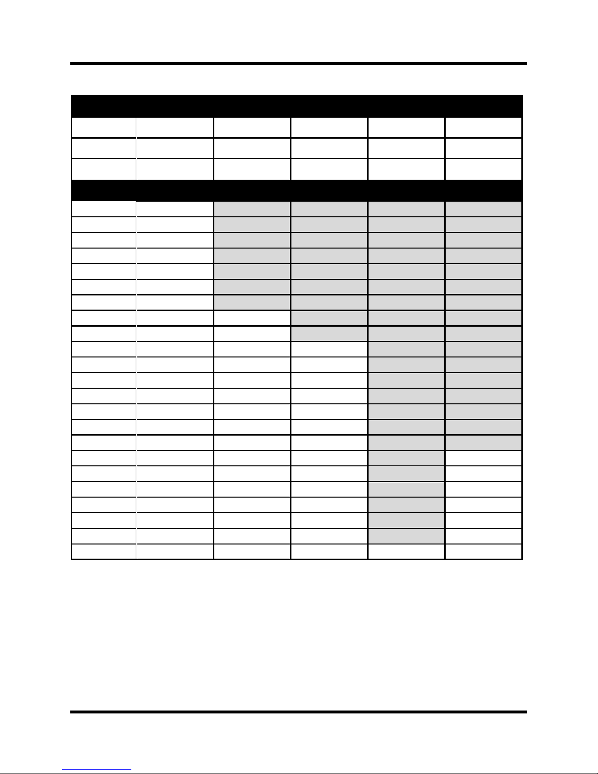
Supported CFM/Duct Sizes for the Duct Mount Housing
Units Duct Size
Inches 12 x 12 12 x 24 18 x 18 24 x 24 24 round
Feet 1 x 1 1 x 2 1.5 x 1.5 2 x 2 Pi x 1 x 1
Area (ft2) 1 2 2.25 4 3.14
CFM Ft/min (Based on CFM and Duct Size)
2800
2800
n/a
n/a
n/a
n/a
3000 3000 n/a n/a n/a n/a
3400
3400
n/a
n/a
n/a
n/a
3800
3800
n/a
n/a
n/a
n/a
4000 4000 n/a n/a n/a n/a
4400
4400
n/a
n/a
n/a
n/a
4800
4800
n/a
n/a
n/a
n/a
5000
5000
2500
n/a
n/a
n/a
5400
5400
2700
n/a
n/a
n/a
5800
5800
2900
2578
n/a
n/a
6000
6000
3000
2667
n/a
n/a
6400
6400
3200
2844
n/a
n/a
6800
6800
3400
3022
n/a
n/a
7000
7000
3500
3111
n/a
n/a
7400
7400
3700
3289
n/a
n/a
7800
7800
3900
3467
n/a
n/a
8000
8000
4000
3556
n/a
2548
8400
8400
4200
3733
n/a
2675
8800
8800
4400
3911
n/a
2803
9000
9000
4500
4000
n/a
2866
9400
9400
4700
4178
n/a
2994
9800
9800
4900
4356
n/a
3121
10000
10000
5000
4444
2500
3185
MGS Installation and Operation Manual
8 1000-0085 Rev 0
Section 2. Installation and Wiring
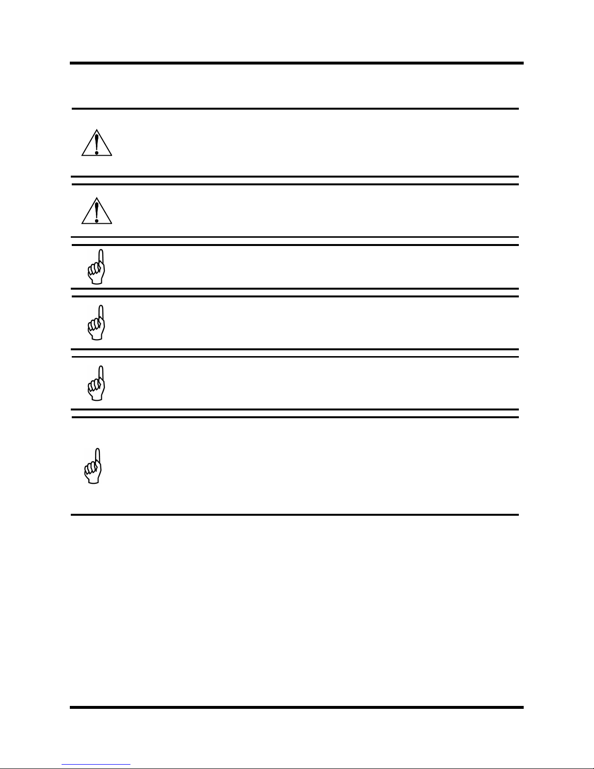
WARNING: Explosion hazard! Do not mount the MGS in an area
that may contain flammable liquids, vapors, or aerosols. Operation
of any electrical equipment in such an environment constitutes a
safety hazard.
CAUTION: The MGS contains sensitive electronic components
that can be easily damaged. Do not touch nor disturb any of these
components.
NOTE: The mounting location of the monitor should allow it to be
easily accessible for visual monitoring and servicing.
NOTE: The monitor must be connected by a marked, suitably
located and easily reached switch or circuit-breaker as means of
disconnection.
NOTE: Connect monitor power and signaling terminals using
wiring that complies with local electrical codes or regulations for the
intended application.
NOTE: This instrument can be equipped with a semiconductor
sensor for the detection of refrigerant, combustible and VOC gases.
Semiconductor sensors are not gas specific and respond to a variety
of other gases including propane exhaust, cleaners, and solvents.
Changes in temperature and humidity may also affect the sensor’s
performance.

MGS Installation and Operation Manual
1000-0085 Rev 0 9
2.1. General Placement Guidelines
NOTE: The MGS should be installed plumb and level and securely
fastened to a rigid mounting surface.
Sensors must be located within the appropriate wire lengths from the central
control unit (if used).
In all cases the sensor supplied is designed for maximum sensitivity to a
particular gas. However, in certain circumstances false alarms may be caused
by the occasional presence of sufficiently high concentrations of other gaseous
impurities. Examples of situations where such abnormalities may arise include
the following:
• Plant room maintenance activity involving solvent or paint fumes or
refrigerant leaks.
• Accidental gas migration in fruit ripening/storage facilities (bananas -
ethylene, apples - carbon dioxide).
• Heavy localised exhaust fumes (carbon monoxide, dioxide, propane)
from engine-driven forklifts in confined spaces or close to sensors.
Murco recommends setting the alarm delay to minimise false alarms.
2.2. Components and Access Overview
NOTE: The wiring is the same for the electro-chemical, semi-
conductor, and infrared models. The controller wiring is the same
for all controllers.
There is a 5-minute power-up delay to allow the sensor to stabilise. Refer to
Figure 2 and Figure 3 for internal components and wiring.

MGS Installation and Operation Manual
10 1000-0085 Rev 0
Figure 2. EC or IR Sensor Components and Wiring
 Loading...