

Page 1

FCC Part 15 Certification
Test Report
2.4 GHz Frequency Hopping Spread Spectrum
(Modular Approval)
FCC ID: HSW-BT2022M
FCC Rule Part: 15.247
ACS Report Number: 03-0193-15BC
Manufacturer: Cirronet, Inc.
Model: BT2022
Manual
5015 B.U. Bowman Drive Buford, GA 30518 USA Voice: 770-831-8048 Fax: 770-831-8598
Page 2

HN-110
User’s Guide
5375 Oakbrook Parkway
Norcross, Georgia 30093
www.cirronet.com
+1 678 684-2000
Page 3

Note: This unit has been tested and found to comply
with the limits for a class A digital device, pursuant
to part 15 of the FCC Rules. These limits are
designed to provide reasonable protection against
harmful interference when the equipment is operated
in a commercial environment. This equipment
generates, uses, and can radiate radio frequency
energy and, if not installed and used in accordance
with the instruction manual, may cause harmful
interference to radio communications. Operation of
this equipment in a residential area is likely to cause
harmful interference in which case the user will be
required to correct the interference at his own
expense. Commensurate with EIRP limits specified
in FCC Rules 15.247b, this device may not be used
with antennas that exceed 36dB of gain in point-topoint applications or 16dB of gain in multi-point
applications.
FCC ID HSW-BT2022
Steps have been taken to insure the accuracy of the contents of this manual. Nevertheless,
Cirronet Incorporated cannot guarantee the accuracy of this manual.
Copyright 2003 Cirronet™ Incorporated
WaveBolt is a trademark of Cirronet Incorporated. Windows is a registered
trademark of Microsoft Corporation.
ii
Page 4

Operational Safety Notes
FCC Notice, U.S.A.
All HopNet products comply with Part 15 of the FCC Rules. Operation is
subject to the following conditions:
This device may not cause harmful interference, and this device must accept
any interference received, including interference that may cause undesired
operation.
This device is specifically designed to be used under Section 15.203 of the
FCC Rules and Regulations. Any unauthorized modifications or changes to
this device may void the user’s authority to operate.
This device is intended to be used only when professionally installed. Failure
to comply with these instructions may also void the user’s authority to operate
this device.
European Community Notice
The HN-110 to which this declaration relates is in conformity with the
following standards or other normative documents:
EN300328
EN301489
EN60950
This device complies with ETS 300.328 of the European Community.
Operation is subject to the following conditions:
This device may not cause interference.
This device must accept interference, including undesired interference that
may impede the operation of this device.
RF Exposure
WARNING: End Users of these systems must be informed that RF exposure
limits may be exceeded if personnel come closer than 45 cm to the antenna
aperture when exceeding 9 dBi of gain in conjunction with the transceiver.
Repairs
Cirronet does not recommend field repairs of the radio equipment. Surface
Mount Technology (SMT) has been used in the production of the transceiver
module, which requires specialized training and equipment for proper
servicing. The equipment should be returned to the factory for any repair.
iii
Page 5

Page 6

Table of Contents
Introduction ...................................................................................................................................... 6
H
OPNET BENEFITS......................................................................................................................... 6
Operating Frequency .............................................................................................................. 6
HopNet Frequency Hopping Spread Spectrum Advantages .................................................. 6
HopNet Data Integrity ............................................................................................................. 6
Flexible Power Management .................................................................................................. 7
DVANCED FEATURES .................................................................................................................... 7
A
T
HE HOPNET FAMILY OF PRODUCTS ............................................................................................... 7
Getting Started................................................................................................................................. 8
INSTALL THE HOPNET CONFIGURATION WIZARD ON A PC. ............................................................... 8
CONNECT THE HN-110 TO THE PC. ................................................................................................ 8
THE SERIAL ADAPTER BOX ........................................................................................................... 10
3 Wire Operation................................................................................................................... 10
Remote Pin-Out, RS-232 ...................................................................................................... 11
GUIDELINES FOR INSTALLATION..................................................................................................... 12
A
IMING THE ANTENNA AND PLACING THE REMOTE ......................................................................... 12
INTERCONNECT CABLE ................................................................................................................. 12
Configuring the Network ................................................................................................................ 13
WinCOM24 Window.............................................................................................................. 13
Configuration Commands.............................................................................................................. 15
ERIAL COMMANDS ...................................................................................................................... 15
S
N
ETWORK COMMANDS ................................................................................................................. 16
STATUS COMMANDS ..................................................................................................................... 17
MODEM COMMAND SUMMARY ....................................................................................................... 18
Troubleshooting............................................................................................................................. 19
OVERVIEW ................................................................................................................................... 19
Introduction ........................................................................................................................... 19
Transceiver Requirements.................................................................................................... 19
COMMON SYSTEM PROBLEMS....................................................................................................... 20
GUIDELINES FOR REDUCING INTERFERENCE .................................................................................. 21
Introduction ........................................................................................................................... 21
Guidelines for Setting Up the Network.................................................................................. 21
Guidelines for Selecting Your Site ........................................................................................ 21
GUIDELINES FOR AVOIDING TERRAIN OBSTRUCTIONS .................................................................... 22
CUSTOMER SUPPORT ................................................................................................................... 23
Introduction ........................................................................................................................... 23
Technical Assistance ............................................................................................................23
Factory Repairs..................................................................................................................... 23
Technical Specifications ................................................................................................................ 24
Electrical................................................................................................................................ 24
Mechanical............................................................................................................................ 25
Environmental ....................................................................................................................... 25
Glossary of Terms ......................................................................................................................... 26
Warranty ........................................................................................................................................ 27
v
Page 7

Configuring the Network
Introduction
The HopNet 10 Series family of products provides reliable wireless connectivity for
point-to-point applications. HopNet products employ frequency hopping spread
spectrum technology. This technology ensures:
• Maximum resistance to noise
• Maximum resistance to multipath fading
• Robustness in the presence of interfering signals
The HN-110 is NEMA 4X weatherproof versions of the HopNet product line. The
interface to the 110 allows the Host to communicate with the Remote unit through an
integrated 6 ft (2 meter) cable. The HN-110 can act as either a base or remote.
The HN-110 Remote has an internally mounted 6 dBi patch antenna. The built-in
antenna of the HN-110 case greatly eases outdoor installation since no antenna
feedline cable or adapters are needed. The 6 dBi antenna gain increases the radiated
EIRP to +20 dBm and the effective receiver sensitivity to –86 dBm.
HopNet Benefits
The HopNet family of products is built with rugged enclosures compliant with IP 66
and NEMA 4X standards for outdoor and harsh industrial environments. All Hopnet
products work with each other and can be mixed and matched in a single network.
Operating Frequency
The HopNet family operates in the 2.4 GHz ISM band that allows for license-free use
and worldwide compliance.
HopNet Frequency Hopping Spread Spectrum Advantages
In the frequency domain, a multipath fade can be described as a frequency selective
notch that shifts in location and depth over time. Multipath fades typically occupy
five percent of the band. A conventional radio system typically has a five percent
chance of signal impairment at any given time due to multipath fading.
Frequency Hopping Spread Spectrum reduces the vulnerability of a radio system to
both interference from jammers and multipath fading by distributing or spreading the
signal over a larger region of the frequency band.
The fade resistant, HopNet frequency-hopping technology employs up to 79 channels
and switches channels over 1600 times a second to achieve high reliability
throughput.
HopNet Data Integrity
An on-board 3 KB buffer and error correcting over-the-air protocol ensure data
integrity even in the presence of weak signals or jammers. The serial interface
handles both data and control of asynchronous data rates of up to 115 Kbps.
6 HopNet 110
Page 8

Configuring the Network
Flexible Power Management
You can place the transceiver module in a power-save mode, which enables smart
power management. Smart power management allows a remote unit to drop into a
lower current standby mode during transmission or receiving gaps.
This feature also allows Hopnet products to be used in various countries where the
output power requirements may vary due to regulation.
Advanced Features
HopNet modems have many advanced features:
• Employ frequency hopping technology with up to 79 channels in the 2402 to
2480 MHz frequency range
• Support RS-232 interface
• Use transparent ARQ protocol
• Use same hardware for all supported data rates
• Supports up to 115 Kbps asynchronous data rates
• Full Duplex operation
• Store setup configuration in nonvolatile memory (FLASH)
• Fast acquisition – less than 2 seconds is the typical time to acquire hopping
pattern
• Smart power management features
The HopNet Family of Products
The HopNet family consists of the following products:
HopNet 110 7
Page 9
Configuring the Network
Getting Started
A pair of HN-110s is set up by performing the following steps:
• Install the HopNet Wizard configuration program on a PC
• Connect the HN-110 to the PC
• Run a communications test
These steps are described in detail below. Other steps you may want to perform
include:
• Change the baud rate
Refer to the Configuring the Network section of this manual for details on these steps.
Install the HopNet Configuration Wizard on a PC.
The HopNet Configuration Wizard is located on the software and documentation CD
included in the HN-110 package. Install the program by inserting the CD in the PC
and following the installation wizard. If autorun has been turned off, double-click on
setup.exe on the CD to start the wizard.
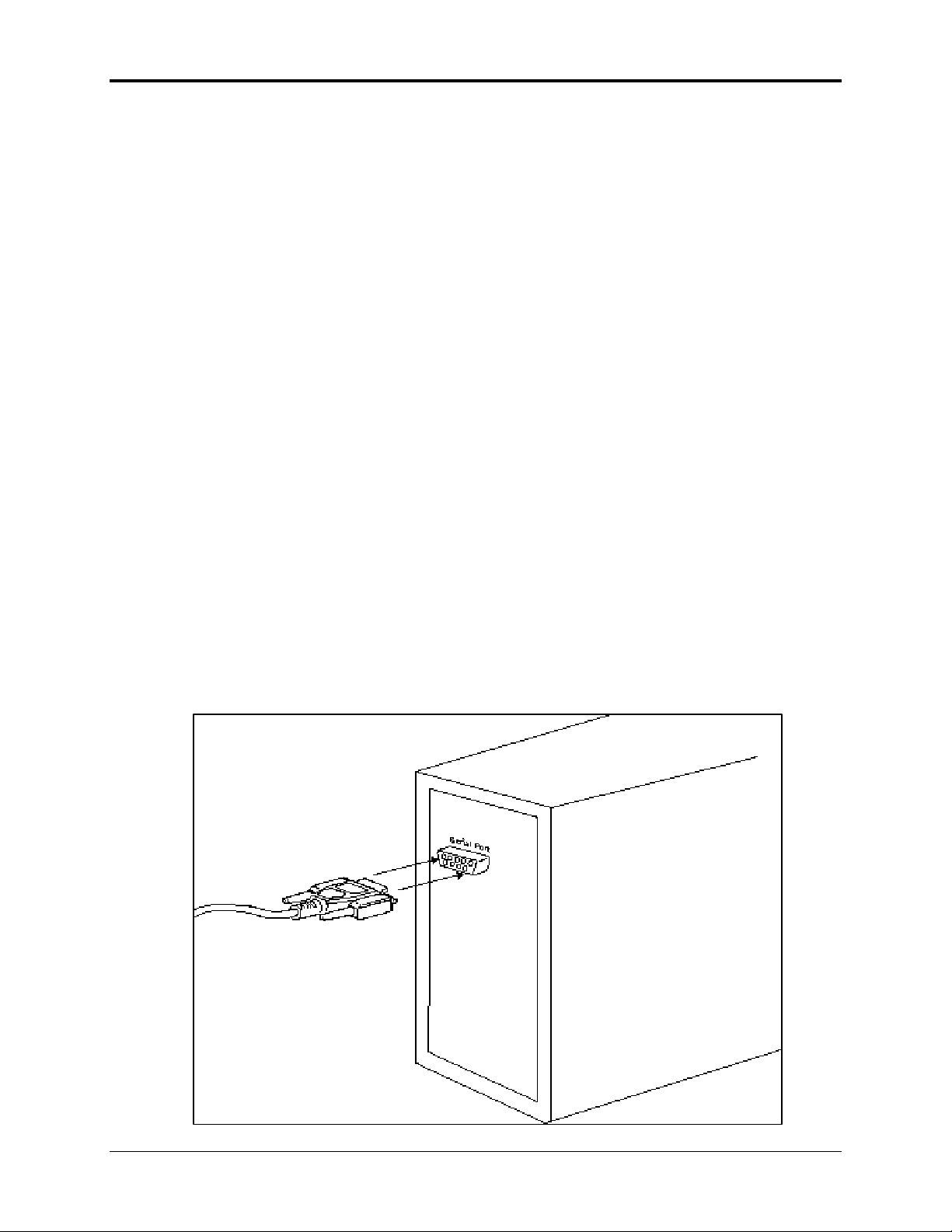
Connect the HN-110 to the PC.
Connect the serial adapter box to a serial port on the PC using the serial cable
provided.
Connect one end of the
serial cable to a serial
port on the PC.
8 HopNet 110
Page 10

Configuring the Network
Connect the other end of the
serial cable to the serial
adapter box.
Connect the end of the cable from the HN-110 to the small serial adapter box.
Plug the RJ-45 type connector
from the HN-110 into the serial
adapter box.
Connect power to the HN-110 by plugging one end of the wall-mount power supply
into the serial adapter box and the other end into a wall outlet. A green LED on the
serial adapter box will turn on indicating power is present.
Green LED is on when
power is applied.
HopNet 110 9
Page 11

Configuring the Network
The Serial Adapter Box
The HN-110 remote interfaces with the user’s hardware through a serial adapter box.
The interface adapter supplies power and signal to the remote unit. The interface to
the remote unit is a standard RS-232 DB-9 serial interface. To have all functions of
the HN-110 available, including configuration and hardware flow control, the eight
signal lines must be connected. The HN-110 serial connector is set up as a DCE
device. This allows communication with a PC using the straight through serial cable
provided with the HN-110. To connect the HN-110 to another DCE device, a crossover cable must be used. The connector pin-out is detailed in the figure and table
below.
3 Wire Operation
If configuration and hardware flow control is not necessary, the HN-110 can be used
in 3-wire mode. In this mode, only Ground, Receive Data and Transmit data are
connected
5 Ground
9 Not Used
8 Clear to Send (CTS)
7 Request to Send (RTS)
6 Data Set Ready (DSR)
4 Data Terminal Ready (DTR)
3 Transmit Data (TX)
2 Receive Data (RX)
1 Data Carrier Detect (DCD)
RS-232 Interface
10 HopNet 110
Page 12

Configuring the Network
Remote Pin-Out, RS-232
Pin Number Signal Type Description
1 DCD Output Data Carrier Detect. For remotes, DCD indicates
that the remote has successfully acquired the
hopping pattern.
2 RXD Output Output for received serial data.
3 TXD Input Input Serial Data to be transmitted
4 DTR Input Data Terminal Ready. Sleep/ wakes radio
transceiver.
5 GND - Signal and Chassis Ground
6 DSR Output Data Set Ready. Response to DTR.
7 RTS Input Request to Send. Gates the flow of receive data
from the radio to the user on or off. In normal
operation signal should be asserted.
8 CTS Output Clear to Send. Used to control transmit flow from
the user to the user to the radio. The WIT 2410
radio module supports hardware flow control
only and does not support software flow control
(e.g. Xon-Xoff).
9 Not Used - Not Used
Note: When the HN-110 is used as a three wire serial device, DTR and RTS do not have to
be used.
HopNet 110 11
Page 13

Configuring the Network
Guidelines for Installation
When installing your system, always consider the following points:
For systems with constant interference present, you may need to change the polarity
of the antenna system and reduce data streams. Groups of short data streams are more
reliable and have a better chance of success in the presence of interference than do
long data streams.
Systems installed in rural areas are least likely to encounter urban interference.
Multiple HopNet systems can operate in close proximity to each other but require a
unique network address.
Aiming the Antenna and Placing the Remote
Use the following guidelines for aiming the antenna and placing the Remote.
Do not place anything immediately in front of the antenna that could obstruct its
radiation pattern. Because the antenna in the HopNet Remote is inside the unit, the
antenna must have a clear line of sight.
Use the sticker on the HN-110 Remote unit to help you locate and aim the antenna.
The sticker indicates which direction the antenna is pointing.
Be sure the antenna end of the HN-110 Remote faces the Base or Repeater that it is
communicating with. Our tests have found that antenna placement is not critical as
long as the patch antenna is facing in the general direction of the other end of the link.
If possible, place the Remote unit at a higher elevation than the structures surrounding
it to increase range and link reliability. Since the Remote will operate with up to 100
feet of interconnect cable between it and the Host, you can mount the unit on top of a
building or other structure that will provide higher elevation.
Interconnect Cable
The HN-110 comes with a 6’ (2 meters) high quality interconnect cable. The cable
may be lengthened by adding an additional 50’ cable (part no.: CBLEXT50). The
maximum cable length that the HN-110 will support is 100’ (30 meters).
12 HopNet 110
Page 14

Configuring the Network
Configuring the Network
WinCOM24 Window
The program WinCOM24 window can be used to enter these other configuration
commands. Please be aware that an improper commands or a wrong combination of
configuration values can affect the radio’s performance.
When the window is opened, the sign-on banner is displayed. The banner indicates
the radio firmware version, whether the radio is operating as a base or a remote and
the unique factory serial number of the radio module in the HN-110.
The HN-110 radio is normally in data mode – data that is sent to it from the PC is
transmitted over the wireless connection. To change configuration parameters, the
radio must be put into configuration mode. There are two ways to enter configuration
mode. The first way is immediately after turning the HN-110 on to send the string
“:wit2410” to the radio. This can be done in the WinCom window by pressing the F3
key. The second method is to de-assert and then re-assert DTR and then send the
“:wit2410” string to the radio. This can be done in the WinCom window by pressing
the F1 key twice and then the F3 key. When the radio is in configuration mode, a “>”
prompt character is displayed in the WinCom window.
HopNet 110 13
Page 15

Configuring the Network
Configuration parameters are sent to the radio by entering them in the WinCom
window after the “>” prompt and pressing the Enter key. The radio will echo back the
new parameter value indicating the parameter was successfully set. If an invalid
command or value is enter, the radio will respond with “Error.” Until the command to
save the parameters is issued, the new parameters will only be valid until power is
cycled or DTR is toggled. New parameter values that have been issued are saved to
non-volatile memory using the “m>” command. Refer to the Memory Commands
section for details on this and other helpful memory commands.
To exit configuration mode from the WinCom screen, use the “z>” command and
press Enter. The return to the data mode is indicated by an absence of the “>” prompt.
Refer to the Configuration Commands section below for details on all the
configurable parameters.
14 HopNet 110
Page 16

Configuring the Network
Configuration Commands
The HN-110 has a wide selection of configuration parameters that can be modified
using one or more of the configuration commands. The commands can be grouped
into five categories based on what they do. The five sections are:
• Serial Interface Commands
• Network Commands
• Protocol Commands
• Status Commands
• Memory Commands
Each command is described in detail below. In the descriptions, brackets ([,]) are
used to denote a set of optional arguments. Vertical slashes (|) separate selections.
For example, given the string sd[?|0..1d8], some legal commands are wn?, wns, wna
and wn7. Most commands which set a parameter also have a ? option which causes
the modem to respond with the current parameter setting, e.g., sd? When using the
WinCom window to enter these commands, the syntax must be followed as described.
Each modem command must be followed by either a carriage return or a line feed.
Serial Commands
These commands affect the serial interface between the modem and the host. The
default settings are 9600 bps.
Command Description
sd[?|00..1d8]
Set Data Rate Divisor
Sets the serial bit rate between the modem and the host. This command takes effect
immediately and will require adjusting the host serial rate to agree. Nonstandard rates
may be programmed by entering a data rate divisor computed with the following
formula:
Set Data Rate Divisor
Data Rate Divisor (hex)
1200 bps = 5
2400 bps = a
9600 bps = 27
14400 bps = 3b
19200 bps = 4f
28800 bps = 76
38400 bps = 9d
57600 bps = ec
115200 bps = 1d8
RATE = DIVISOR/0.004096
Round all non-integer values down.
HopNet 110 15
Page 17

Configuring the Network
Network Commands
Network commands are used to set up a HopNet network and to set radio addressing
and configuration.
Command Description
wb[?]
wh
wm
wl
Set Transceiver Mode
0 = remote (default)
1 = base station
Factory serial number high byte.
Factory serial number middle byte.
Factory serial number low byte.
Set Transceiver Mode
Read modem operation as either base station or remote. Default is remote.
Read Factory Serial Number High, Middle and Low Bytes.
These read only commands return one of the three bytes of the unique factory-set
serial number, which are also visible in the startup banner.
16 HopNet 110
Page 18

Configuring the Network
Status Commands
These commands deal with general interface aspects of the operation of the HopNet.
Command
zb[?|0|1]
zh?
zm?
zl?
z>
z!
do[?|0|1]
Banner Display Disable
Description
Banner Display Disable
0 = disabled
1 = enabled (default)
Read factory serial number high byte.
Read factory serial number middle byte.
Read factory serial number low byte.
Exit Modem Control Mode
Software Reset
DTR Operational
0 = does not obey DTR
1 = does obey DTR
2 = reads status
Enables or disables display of the banner string and revision code automatically at
power-up. May be disabled to avoid being mistaken for data by the host.
Read Factory Serial Number High, Middle and Low Bytes.
These read only commands return one of the three bytes of the unique factory-set
serial number, which are also visible in the startup banner.
DTR Operation
Sets whether or not the radio obeys DTR .
HopNet 110 17
Page 19

Configuring the Network
Memory Commands
The user is able to store a configuration in nonvolatile memory, which is loaded
during the initialization period every time the radio is powered up. Note that changes
to the serial port baud rate- from recalling the factory defaults or recalling memory will not take effect until DTR is toggled or power to the radio is cycled.
Command
Description
m0
m>
Recall Factory Defaults
Store Memory
Recall Factory Defaults
Resets the HopNet to its factory default state. This is useful for testing purposes or if
there is a problem in operation of the system and the configuration is suspect. Use
the Store Memory command afterwards if you wish the factory default settings to be
remembered the next time you cycle power or reset the radio.
Store Memory
This command is necessary after any command to change the data rate, transceiver
address, or other radio setting that you wish to make permanent.
Modem Command Summary
Serial Commands
sd[?|00..1d8] Set Data Rate Divisor
Network Commands
wb[?|0|1] Set Transceiver Mode
wh? Set Serial Number High Byte to communicate with
wm? Set Serial Number Medium Byte to communicate with
wl? Set Serial Number Low Byte to communicate with
Status Commands
zb[?|0|1] Banner Display Disable
zh? Read Factory Serial Number High Byte
zm? Read Factory Serial Number Middle Byte
zl? Read Factory Serial Number Low Byte
z> Exit Modem Control Mode
z! Software Reset
do DTR Operation
Memory Commands
m0 Recall Factory Defaults
m> Store Memory
18 HopNet 110
Page 20

Troubleshooting
Troubleshooting
Overview
Introduction
Troubleshooting the HopNet products is not difficult, but it does require a logical
approach. It is best to begin troubleshooting at the base station because the rest of the
system synchronizes to it. If the base station has problems, the entire network will be
compromised.
This chapter provides troubleshooting information for your HopNet products.
Transceiver Requirements
For proper operation, all transceivers in the network must meet these basic
requirements:
Adequate and stable power
Secure connections ( Power, RF, and Data)
Proper programming especially Hop Duration and Network Address
HopNet 110 19
Page 21

Troubleshooting
Common System Problems
The following table offers suggestions for resolving some common system problems
that the operator may experience from the radio system. If problems persist, contact
the factory for further assistance.
Problem System Checks
Unit is inoperative 1. Check for proper DC voltage at the power
2. Momentarily remove and reapply power.
connector.
No Carrier Detect at
remote units or
intermittent
Interference is
suspected
1. Check for secure interface connections at the
transceiver.
2. Check antenna, feedline, connectors, and reflective
power.
3. If remote unit is in synchronization but
performance is poor, it may indicate antenna
problems. Check for properly aligned antenna
headings.
4. Verify proper programming of the system
parameters.
1. Verify that the system has a unique network
address. Nearby systems with same address will
cause interference problems.
2. If Omni-directional antennas are used with the
remote units, consider using a directional type
instead. This will often limit interference to and
from other stations.
20 HopNet 110
Page 22

Troubleshooting
Guidelines for Reducing Interference
Introduction
The transceivers share the same frequency spectrum with other services and other
Part 15 devices in the US. Because of this, you may not achieve 100 percent error free
communications in a given location. You should also expect some level of
interference. However, the flexible design of the radio and the hopping pattern should
allow for adequate performance as long as care is taken in choosing station location,
configuration parameters of the transceivers, and protocols techniques.
Use the following guidelines to reduce interference in your HopNet system.
Guidelines for Setting Up the Network
In general, the following points should be followed when setting up a network:
Systems installed in rural areas are least likely to encounter interference.
If possible, use directional antennas at remote sites. The directional antennas confine
the transmission path and reception pattern to a comparatively narrow lobe, which
minimizes interference from stations located outside the pattern.
Multiple HopNet systems can co-exist in close proximity to each other with very
minor interface as long as they are assigned a unique network address. Each network
address has a different hop pattern.
If interference is suspected from a similar operating system, change the antenna
polarization. This will provide an additional 20dB of attenuation to interference.
For indoor applications, set all transceivers for the lowest level necessary for reliable
communications. This lessens the chance of interference from nearby systems.
Guidelines for Selecting Your Site
Use these guidelines to select a proper site for the master remote stations. Suitable
sites must provide the following:
An adequate and stable source of primary power.
Antenna location that provides an unobstructed transmission path in the direction of
the associated units.
Proper antenna selection, data access, and feedline cabling
A clear line-of-sight. Microwave radio signals travel primarily by line-of-sight, and
obstructions between the sending and receiving stations will affect system
performance.
HopNet 110 21
Page 23

Troubleshooting
Guidelines for Avoiding Terrain Obstructions
The HopNet transceivers operate in the 2.4 GHz frequency band. While this band
offers many advantages over the VHF band for data transmission, it is also more
prone to signal attenuation from obstructions such as terrain, foliage, buildings and
anything else in the transmission path.
Use the following guidelines to avoid terrain obstructions:
A line-of-sight transmission path between the base and the associated remote sites
provides for the most reliable transmission path.
A line-of-sight path can be achieved by mounting the station antenna on a tower or
elevated structure that raises it to a sufficient level to clear surrounding terrain and
other obstructions.
The importance of a clear transmission path relates closely to the distance to be
covered. If the system is to cover only a limited geographical area such as 1-3 miles,
then some obstructions may be tolerated with minimal impact.
For longer-range systems, any substantial obstruction in the transmission path could
compromise the performance of the system.
22 HopNet 110
Page 24

Troubleshooting
Customer Support
Introduction
Cirronet, Inc. products are designed for long life and trouble free operation. The
following information is provided if servicing becomes necessary.
Technical Assistance
Technical assistance for Cirronet products is available during the hours of 9:00 A.M –
5:30 P.M. Eastern Standard Time. When calling, please have available the complete
model name, serial number, and a complete description of the problem. Most
problems can be resolved without returning the unit to the factory.
The following telephone numbers are available for assistance.
Phone 678-684-2000
Fax 678-684-2001
Factory Repairs
If return of equipment is necessary, you will be issued a Return Material
Authorization number (RMA #). The RMA # will help expedite the repair so that
equipment can be returned as quickly as possible. Please be sure to include the
RMA number (#) on the outside of the shipping box and on any correspondence
relating to the repair. Any equipment returned without an RMA # may be delayed in
the repair cycle.
Please be sure to carefully package all items to be returned and address to:
CIRRONET, INC.
5375 Oakbrook Parkway
Norcross, GA 30093
RMA # ***
HopNet 110 23
Page 25

Specifications
Technical Specifications
Refer to the tables below for the technical specifications for the HN-110 Remotes.
Electrical
Specification Value
Transmitter FCC ID
Transmit Power EIRP: +20 dBm Nominal
Number of Channels 79 US
Line-of-Sight Range Greater than 3.5 miles
Frequency Band 2402-2480 MHz (USA)
Approvals US FCC: Part 15. 203
Receiver Sensitivity -86 dBm
Industry Canada
European Community: ETS 300.328 Compliance
Data Interface RS-232
Input Power at Connector 9 - 30 VDC Operating
200 mA Typical (750 mA surge)
24 HopNet 110
Page 26

Troubleshooting
Mechanical
Specification Value
Case NEMA 4X, IP 66
Size 5.1 in. x 3.1 in. x 1.4 in.
130mm x 80mm x 35mm
Weight 1.75 lb (including cable)
794 g
Data Connector DB-9 Female
Interconnect Cable
Connector
Environmental
Specification Value
Temperature Range -30 to +70 degrees C
Humidity 95% at +40 degrees C, Non-condensing
RJ-45
HopNet 110 25
Page 27

Glossary
Glossary of Terms
Refer to the following list of terms that may be unfamiliar to you. These terms are used
throughout this document.
Term Definition
ARQ Automatic Repeat Request. The operation in which the radio
will re-send the data until it is received correctly.
bps Bits-per-second. A measure of information transfer rate of
digital data across a channel.
Decibel A measure of the ratio between two signal levels. Used to
express either loss or gain.
dBi Decibels referenced to an ideal isotropic radiator in free space.
Used to express antenna gain.
dBm Decibels referenced to 1 milliwatt. An absolute unit used to
measure signal power. Transmitter power output or received
signal strength.
DCE Data Communications Equipment. A device that receives data
in the form of digital signals at its input. The modem side of a
computer-to-modem connection.
DCD Data Carrier Detect.
DTE Data Terminal Equipment. A device that provides data in the
form of digital signals at its output. The computer side of a
computer-to-modem connection.
EIRP Effective Isotropic Radiated Power.
ISM Industrial, Scientific, or Medical band operating at 2.4 GHz.
Allows use of a radio without a license, but the equipment must
be immune to interference from other users in the band and
approved for use in the intended country.
Latency The delay between when data is received on TX until it is
output on RX.
RMA Return Material Authorization.
RTU Remote Terminal Unit. A device used in data collection.
TDMA Time Division Multi Access. A time slot multiplexing protocol
for multinode networking.
26 HopNet 110
Page 28

Warranty
Warranty
Seller warrants solely to Buyer that the goods delivered hereunder shall be
free from defects in materials and workmanship, when given normal, proper
and intended usage, for twelve (12) months from the date of delivery to
Buyer. Seller agrees to repair or replace at its option and without cost to
Buyer all defective goods sold hereunder, provided that Buyer has given
Seller written notice of such warranty claim within such warranty period. All
goods returned to Seller for repair or replacement must be sent freight prepaid
to Seller’s plant, provided that Buyer first obtain from Seller a Return Goods
Authorization before any such return. Seller shall have no obligation to make
repairs or replacements which are required by normal wear and tear, or which
result, in whole or in part, from catastrophe, fault or negligence of Buyer, or
from improper or unauthorized use of the goods, or use of the goods in a
manner for which they are not designed, or by causes external to the goods
such as, but not limited to, power failure. No suit or action shall be brought
against Seller more than twelve (12) months after the related cause of action
has occurred. Buyer has not relied and shall not rely on any oral
representation regarding the goods sold hereunder, and any oral representation
shall not bind Seller and shall not be a part of any warranty.
THE PROVISIONS OF THE FOREGOING WARRANTY ARE IN LIEU OF ANY
OTHER WARRANTY, WHETHER EXPRESS OR IMPLIED, WRITTEN OR ORAL
(INCLUDING ANY WARRANTY OR MERCHANT ABILITY OR FITNESS FOR A
PARTICULAR PURPOSE). SELLER’S LIABILITY ARISING OUT OF THE
MANUFACTURE, SALE OR SUPPLYING OF THE GOODS OR THEIR USE OR
DISPOSITION, WHETHER BASED UPON WARRANTY, CONTRACT, TORT OR
OTHERWISE, SHALL NOT EXCEED THE ACTUAL PURCHASE PRICE PAID BY
BUYER FOR THE GOODS. IN NO EVENT SHALL SELLER BE LIABLE TO
BUYER OR ANY OTHER PERSON OR ENTITY FOR SPECIAL, INCIDENTAL OR
CONSEQUENTIAL DAMAGES, INCLUDING, BUT NOT LIMITED TO, LOSS OF
PROFITS, LOSS OF DATA OR LOSS OF USE DAMAGES ARISING OUT OF THE
MANUFACTURE, SALE OR SUPPLYING OF THE GOODS. THE FOREGOING
WARRANTY EXTENDS TO BUYER ONLY AND SHALL NOT BE APPLICABLE TO
ANY OTHER PERSON OR ENTITY INCLUDING, WITHOUT LIMITATION,
CUSTOMERS OF BUYERS
HopNet 110 27
 Loading...