


WIT5811
5.8GHz Spread Spectrum
Wireless Industrial Transceiver
Integration Guide
5375 Oakbrook Parkway
Norcross, Georgia 30093
www.cirronet.com
+1 (678) 684-2000

Note: This unit has been tested and found to
comply with the limits for a class B digital device,
pursuant to part 15 of the FCC Rules. These
limits are designed to provide reasonable
protection against harmful interference when the
equipment is operated in a commercial
environment. This equipment generates, uses,
and can radiate radio frequency energy and, if not
installed and used in accordance with the
instruction manual, may cause harmful
interference to radio communications. Operation
of this equipment in a residential area is likely to
cause harmful interference in which case the user
will be required to correct the interference at his
own expense. Commensurate with EIRP limits
specified in FCC Rules 15.247b, this device may
not be used with antennas that exceed 36dB of
gain in point-to-point applications or 16dB of gain
in multi-point applications.
If the WIT5811 is installed within another device the outside of the device into which the
WIT5811 is installed must also display a label referring to the enclosed module. The label
required for the WIT5811 module is as follows: Transmitter Module FCCID: HSW-5811M.
About This Manual
This manual is designed to allow integration of the Cirronet WIT5811 OEM module into
complete products. Care has been taken to try and make sure all of the information in this
manual is accurate. However, specifications can change over time and Cirronet cannot guarantee
the accuracy of this information. If you have any questions on any information in this manual,
please contact Cirronet Technical Support at +1-678 684 2000.
Cirronet is a trademark of Cirronet Incorporated. All other trademarks belong to their
respective companies.

INFORMATION TO THE USER
FCC Class B:
“NOTE: This equipment has been tested and found to comply with the limits for a Class B
digital device, pursuant to Part 15 of the FCC Rules. These limits are designed to provide
reasonable protection against harmful interference in a residential installation. This equipment
generates, uses and can radiate radio frequency energy and, if not installed and used in
accordance with the instructions, may cause harmful interference to radio communications.
However, there is no guarantee that interference will not occur in a particular installation. If this
equipment does cause harmful interference to radio or television reception, which can be
determined by turning the equipment off and on, the user is encouraged to try to correct the
interference by one or more of the following measures:
• Reorient or relocate the receiving antenna.
• Increase the separation between the equipment and receiver.
• Connect the equipment into an outlet on a circuit different from that to which the
• Consult the dealer or an experienced radio/TV technician for help.”
All Equipment:
Warning: Changes or modifications to this device not expressly approved by Cirronet
Incorporated could void the user’s authority to operate the equipment.
RF Exposure (Intentional Radiators Only)
In accordance with FCC requirements of human exposure to radiofrequency fields, the radiating
element shall be installed such that a minimum separation distance of 20 cm will be maintained.
Industry Canada
All Equipment:
This Class [B] digital apparatus meets all requirements of the Canadian Interference Causing
Equipment Regulations. Operation is subject to the following two conditions: (1) this device
may not cause harmful interference, and (2) this device must accept any interference received,
including interference that may cause undesired operation.
Cet appareillage numérique de la classe [B] répond à toutes les exigences de l'interférence
canadienne causant des règlements d'équipement. L'opération est sujette aux deux conditions
suivantes: (1) ce dispositif peut ne pas causer l'interférence nocive, et (2) ce dispositif doit
accepter n'importe quelle interférence reçue, y compris l'interférence qui peut causer
l'opération peu désirée.
Notice to WIT5811 users/installers using the following fixed antennas:
Mobile Mark 14dBi Corner Reflector ,
Cirronet 14dBi patch,
The field strength radiated by any one of these antennas, when connected to a transmitting
WIT5811 module, may exceed FCC mandated RF exposure limits. FCC rules require
professional installation of these antennas in such a way that the general public will not be closer
than 20 m from the radiating aperture of any of these antennas. End users of these systems must
also be informed that RF exposure limits may be exceeded if personnel come closer than 20 cm
to the apertures of any of these antennas.
receiver is connected.

Notice to WIT5811 users/installers using the following mobile antennas:
Mobile Mark 9dBi omnidirectional,
Mobile Mark 2dBi dipole
The field strength radiated by any one of these antennas, when connected to a transmitting
WIT5811 module, may exceed FCC mandated RF exposure limits. FCC rules require
professional installation of these antennas in such a way that the general public will not be closer
than 20 cm from the radiating aperture of any of these antennas. End users of these systems must
also be informed that RF exposure limits may be exceeded if personnel come closer than 20 cm
to the apertures of any of these antennas.

TABLE OF CONTENTS
1. INTRODUCTION .................................................................................................................. 1
1.1. Why Spread Spectrum?.................................................................................................. 1
1.2. Frequency Hopping vs. Direct Sequence........................................................................ 3
2. RADIO OPERATION ............................................................................................................ 4
2.1. Synchronization and Registration .................................................................................. 4
2.2. Data Transmission .........................................................................................................5
2.2.1. Point-to-Point ........................................................................................................ 5
2.2.2. Point-to-Multipoint ................................................................................................. 6
2.2.3. Handle Assignment............................................................................................... 7
2.5.8. TDMA Operation ................................................................................................... 7
2.2.5. Full Duplex Communication .................................................................................. 9
2.2.6. Error-free Packet Transmission Using ARQ.......................................................... 9
2.3. Modes of Operation ..................................................................................................... 11
2.3.1. Control and Data Modes ..................................................................................... 11
2.3.2. Sleep Mode......................................................................................................... 11
2.3.4. RF Flow Control Mode ........................................................................................ 11
3. PROTOCOL MODES ......................................................................................................... 13
3.1.3. Connect Packet................................................................................................... 15
3.1.4. Disconnect Packet (base only, receive only)...................................................... 15
4. MODEM INTERFACE......................................................................................................... 16
4.1. Interfacing to 5 Volt Systems ....................................................................................... 17
4.2. Evaluation Unit and Module Differences ...................................................................... 17
4.3. Three-Wire Operation .................................................................................................. 17
5. MODEM COMMANDS........................................................................................................ 18
5.1. Serial Commands ........................................................................................................ 18
5.2. Network Commands..................................................................................................... 19
5.3. Protocol Commands .................................................................................................... 20
5.4. Status Commands ....................................................................................................... 22
5.5. Memory Commands..................................................................................................... 23
5.6. Modem Command Summary ....................................................................................... 24
6. WIT5811 DEVELOPER’S KIT ............................................................................................ 25
6.1. WinCOM24 .................................................................................................................. 26
6.2. Demonstration Procedure ............................................................................................ 26
6.3. Troubleshooting ........................................................................................................... 27
7. APPENDICES .................................................................................................................... 29
7.1. Technical Specifications............................................................................................... 29
7.1.1 Ordering Information .......................................................................................... 29
7.1.2. Power Specifications........................................................................................... 29
7.1.3. RF Specifications ................................................................................................ 29
7.1.4. Mechanical Specifications................................................................................... 29
7.2. Serial Connector Pinout ............................................................................................... 30
7.3. Approved Antennas ..................................................................................................... 30
7.4. Technical Support ........................................................................................................ 31
7.5. Reference Design ........................................................................................................ 32

7.6.1 Mechanical Drawing – WIT5811D.............................................................................. 33
7.7 Warranty ....................................................................................................................... 34

1. INTRODUCTION
The WIT5811 radio transceiver provides reliable wireless connectivity for either
point-to-point or multipoint applications. Frequency hopping spread spectrum technology
ensures maximum resistance to noise and multipath fading and robustness in the presence of
interfering signals, while operation in the 5.8GHz ISM band allows license-free use and
worldwide compliance. A simple serial interface supports asynchronous data up to 921600
bps. An on-board 12 KB buffer and an error-correcting over-the-air protocol provide
smooth data flow and simplify the task of integration with existing applications.
- Multipath fading impervious
frequency hopping technology
with 75 frequency channels
(5729 - 5821MHz).
- Supports point-to-point or
multipoint applications.
- Meets FCC rules 15.247 licensefree operation.
- Superior range to 802.11 wireless
LAN devices.
- Transparent ARQ protocol
w/12KB buffer ensures data
integrity.
- Digital addressing supports up to
64 networks, with 62 remotes per
network.
- Low power 3.3v CMOS signals
1.1. Why Spread Spectrum?
The radio transmission channel is very hostile, corrupted by noise, path loss and
interfering transmissions from other radios. Even in a pure interference-free
environment, radio performance faces serious degradation through a phenomenon
known as multipath fading. Multipath fading results when two or more reflected rays of
the transmitted signal arrive at the receiving antenna with opposing phase, thereby
partially or completely canceling the desired signal. This is a problem particularly
prevalent in indoor installations. In the frequency domain, a multipath fade can be
described as a frequency-selective notch that
reflections change due to motion of the radio or objects within its range. At any given
time, multipath fades will typically occupy 1% - 2% of the 5.8 GHz band. This means
that from a probabilistic viewpoint, a conventional radio system faces a 1% - 2% chance
of signal impairment at any given time due to multipath.
- Simple serial interface handles both
data and control at 115,200 or
921600 bps.
- Fast acquisition typically locks to
hopping pattern in 2 seconds or less.
- Selectable 25 mW or 250 mW
transmit power.
- Built-in data scrambling reduces
possibility of eavesdropping.
- Nonvolatile memory stores
configuration when powered off.
- Smart power management features
for low current consumption.
- Dynamic TDMA slot assignment
that maximizes throughput.
shifts in location and intensity over time as
© 2003 Cirronet Incorporated
1 M-5811-0008 Rev -
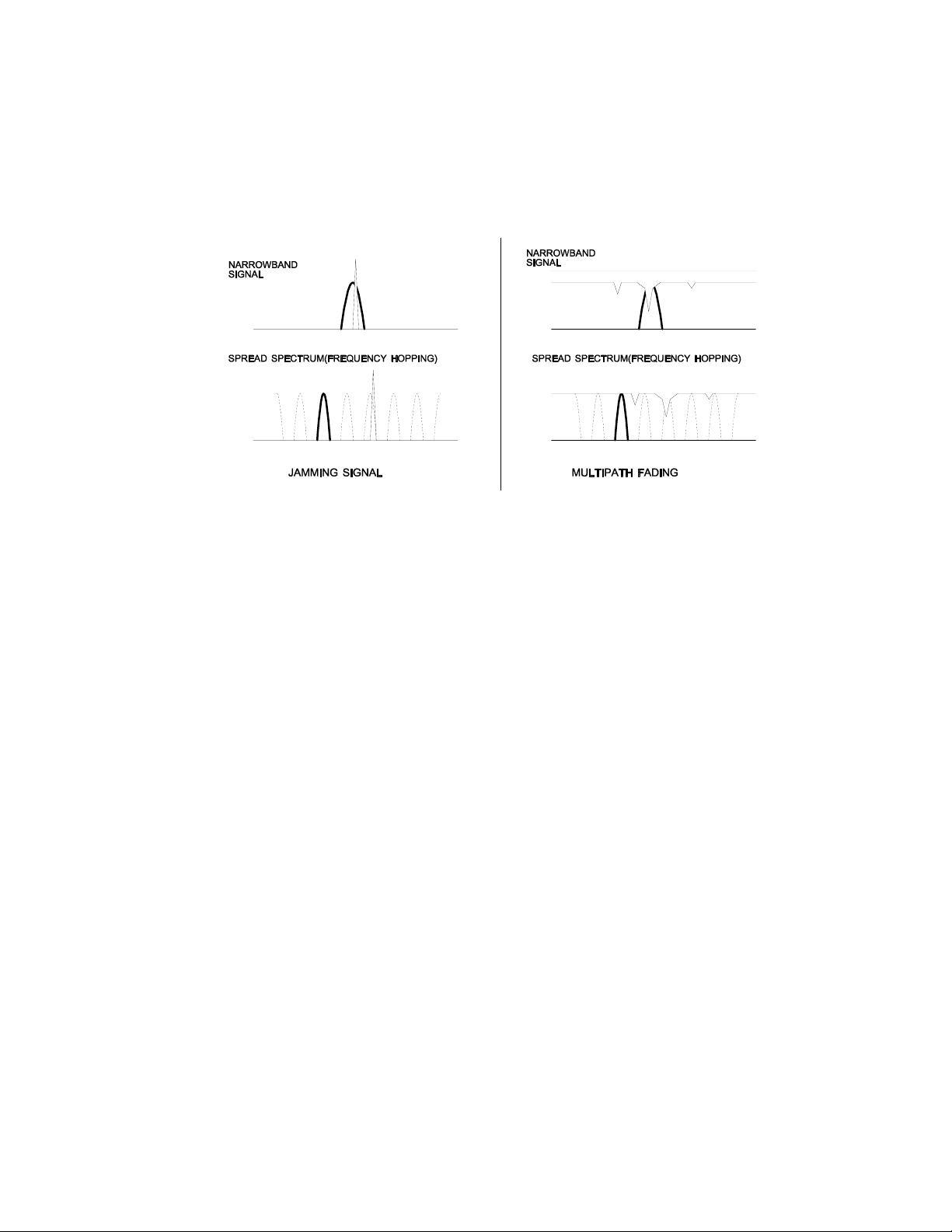
Spread spectrum reduces the vulnerability of a radio system to interference from both
jammers and multipath fading by distributing the transmitted signal over a larger region
of the frequency band than would otherwise be necessary to send the information. This
allows the signal to be reconstructed even though part of it may be lost or corrupted in
transit.
Figure 1
© 2003 Cirronet Incorporated
2 M-5811-0008 Rev -
Narrowband vs. spread spectrum in the presence of interference
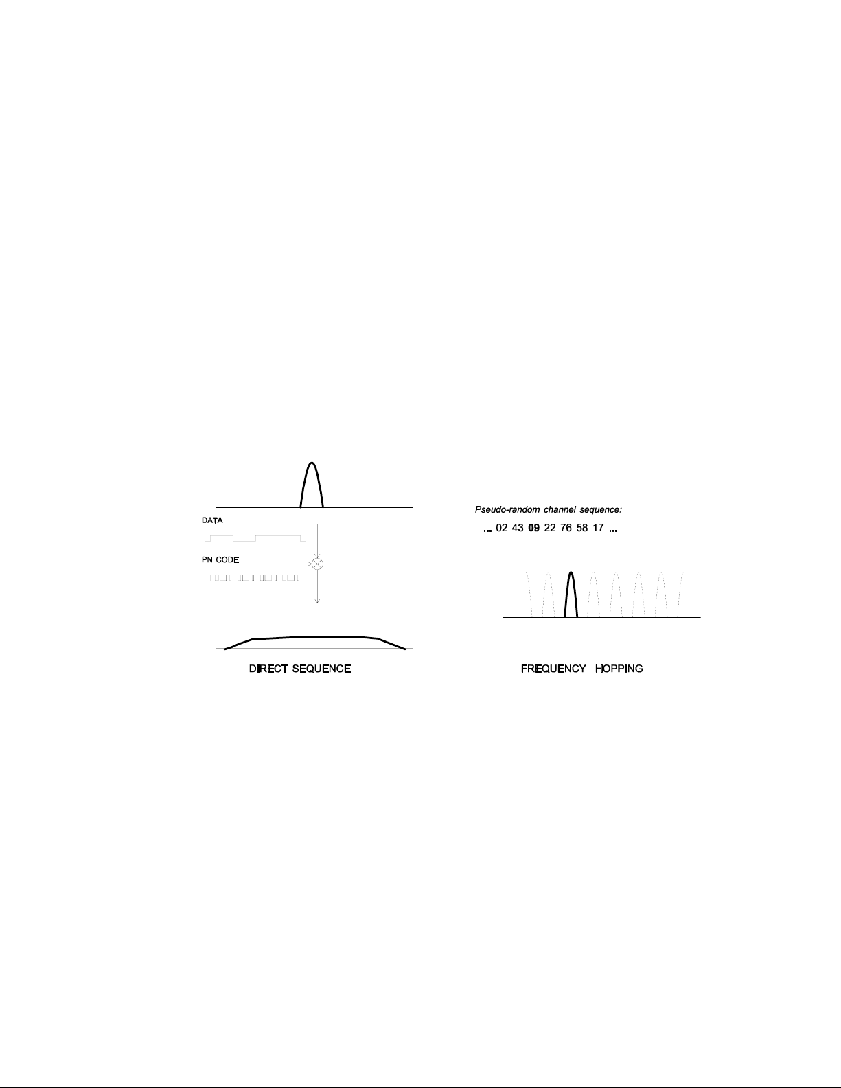
1.2. Frequency Hopping vs. Direct Sequence
The two primary approaches to spread spectrum are direct sequence (DS) and frequency
hopping (FH), either of which can generally be adapted to a given application. Direct
sequence spread spectrum is produced by multiplying the transmitted data stream by a
much faster, noise-like repeating pattern. The ratio by which this modulating pattern
exceeds the bit rate of the baseband data is called the processing gain, and is equal to the
amount of rejection the system affords against narrowband interference from multipath
and jammers. Transmitting the data signal as usual, but varying the carrier frequency
rapidly according to a pseudo-random pattern over a broad range of channels produces a
frequency hopping spectrum system.
Figure 2
Forms of spread spectrum
One disadvantage of direct sequence systems is that due to spectrum constraints and the
design difficulties of broadband receivers, they generally employ only a minimal amount
of spreading (typically no more than the minimum required by the regulating agencies).
For this reason, the ability of DS systems to overcome fading and in-band jammers is
relatively weak. By contrast, FH systems are capable of probing the entire band if
necessary to find a channel free of interference. Essentially, this means that a FH
system will degrade gracefully as the channel gets noisier while a DS system may
exhibit uneven coverage or work well until a certain point and then give out completely.
Because it offers greater immunity to interfering signals, FH is often the preferred
choice for co-located systems. Since direct sequence signals are very wide, they tend to
offer few non-overlapping channels, whereas multiple hoppers may interleave with less
© 2003 Cirronet Incorporated
3 M-5811-0008 Rev -

interference. Frequency hopping does carry some disadvantage in that as the transmitter
cycles through the hopping pattern it is nearly certain to visit a few blocked channels
where no data can be sent. If these channels are the same from trip to trip, they can be
memorized and avoided; unfortunately, this is generally not the case, as it may take
several seconds to completely cover the hop sequence during which time the multipath
delay profile may have changed substantially. To ensure seamless operation throughout
these outages, a hopping radio must be capable of buffering its data until a clear channel
can be found. A second consideration of frequency hopping systems is that they require
an initial acquisition period during which the receiver must lock on to the moving carrier
of the transmitter before any data can be sent, which typically takes several seconds. In
summary, frequency hopping systems generally feature greater coverage and channel
utilization than comparable direct sequence systems. Of course, other implementation
factors such as size, cost, power consumption and ease of implementation must also be
considered before a final radio design choice can be made.
2. RADIO OPERATION
2.1. Synchronization and Registration
As discussed above, frequency hopping radios periodically change the frequency at which
they transmit. In order for the other radios in the network to receive the transmission, they
must be listening to the frequency over which the current transmission is being sent. To do
this, all the radios in the net must be synchronized and must be set to the same hopping
pattern.
In point-to-point or point-to-multipoint arrangements, one radio module is designated as the
base station. All other radios are designated remotes. One of the responsibilities of the base
station is to transmit a synchronization signal to the remotes to allow them to synchronize
with the base station. Since the remotes know the hopping pattern, once they are
synchronized with the base station, they know which frequency to hop to and when. Every
time the base station hops to a different frequency, it immediately transmits a synchronizing
signal.
When a remote is powered on, it rapidly scans the frequency band for the synchronizing
signal. Since the base station is transmitting over up to 75 frequencies and the remote is
scanning up to 75 frequencies, it can take several seconds for a remote to synch up with the
base station.
Once a remote has synchronized with the base station, it must request registration from the
base station. The registration process identifies to the base station the remotes from which
transmissions will be received and not discarded. Registration also allows tracking of
remotes entering and leaving the network. The base station builds a table of serial numbers
of registered remotes. To improve efficiency, the 24-bit remote serial number is assigned a
6-bit “handle” number. Two of these are reserved for system use, thus each base station can
register 62 separate remotes. This handle is how user applications will know the remotes.
© 2003 Cirronet Incorporated
4 M-5811-0008 Rev -

Note that if a remote leaves the coverage area and then re-enters, it may be assigned a
different handle.
To detect if a remote has gone offline or out of range, the registration must be “renewed”
once every 256 hops. Registration is completely automatic and requires no user application
intervention. When the remote is registered, it will receive several network parameters from
the base. This allows the base to automatically update these network parameters in the
remotes over the air. Once a parameter has been changed in the base, it is automatically
changed in the remotes. The parameters automatically changed are hop duration and hop set.
At the beginning of each hop, the base station transmits a synchronizing signal. After the
synchronizing signal has been sent, the base will transmit any data in its buffer. The amount
of data that the base station can transmit per hop is determined by the base slot size
parameter. If there is no data to be sent, the base station will not transmit data until the next
frequency.
The operation for remotes is similar to the base station without the synchronizing signal. The
amount of data a remote can send on one hop is dependent upon the hop duration, the base
slot size and the number of remotes currently transmitting data. A detailed explanation of this
relationship is provided in Section 2.2.3.
Except for the registration process that occurs only when a remote logs onto the network, the
whole procedure is repeated on every frequency hop. Refer to the section on Modem
Commands for complete details on parameters affecting the transmission of data.
2.2. Data Transmission
The WIT5811 supports two network configurations: point-to-point and point-to-multipoint.
In a point-to-point network, one radio is set up as the base station and the other radio is set up
as a remote. In a point-to-multipoint network, a star topology is used with the radio set up as
a base station acting as the central communications point and all other radios in the network
set up as remotes. In this configuration, all communications take place between the base
station and any one of the remotes. Remotes cannot communicate directly with each other.
2.2.1. Point-to-Point
In point-to-point mode, the base station will transmit whatever data is in its buffer limited to
65,536 bytes or as limited by the base slot size. If the base station has more data than can be
sent on one hop, the remaining data will be sent on subsequent hops. In addition to the data,
the base station adds some information to the transmission over the RF link. It adds the
address of the remote to which it is transmitting, even though in a point-to-point mode there
is only one remote. It also adds a sequence number to identify the transmission to the
remote. This is needed in the case of acknowledging successful transmissions and
retransmitting unsuccessful transmissions. Also added is a 24-bit CRC to allow the base to
check the received transmission for errors. When the remote receives the transmission, it
© 2003 Cirronet Incorporated
5 M-5811-0008 Rev -

will acknowledge the transmission if it was received without errors. If no acknowledgment
is received, the base station will retransmit the same data on the next frequency hop.
In point-to-point mode, a remote will transmit whatever data is in its buffer up to the limit of
its transmit slot or slots. If the remote has more data than can be sent on one hop, it will send
as much data as possible as a packet, adding its own address, a packet sequence number and
24-bit CRC. These additional bytes are transparent to the user application if the protocol
mode is 00 (which is the default). In the event a remote has more data to send, the data will
be sent on subsequent hops. If the transmission is received by the base station without errors,
the base station will acknowledge the transmission. If the remote does not receive an
acknowledgment, it will retransmit the data on the next frequency hop. To the user
application, acknowledgments and retransmissions all take place behind the scenes without
the need for user intervention.
The WIT5811 has a point-to-point direct mode which fixes the remote radio’s handle at 30H.
This mode is recommended for point-to-point applications, especially if the remote is likely
to periodically leave and re-enter the coverage area of the base. See the section on Network
Commands for details of this mode.
2.2.2. Point-to-Multipoint
In point-to-multipoint mode, data sent from the user application to the base station must be
packetized by the user application unless the remote device can distinguish between
transmissions intended for it and transmissions intended for other remote devices. This is
necessary to identify the remote to which the base station should send data. When the user
packet is received by the remote, if the remote is in transparent mode (protocol mode 0), the
packetization bytes are stripped by the remote. In this instance the remote host receives just
data. If the remote is not in transparent mode, the remote host will receive the appropriate
packet header as specified by the remote’s protocol mode. Refer to the section Protocol
Modes for details on the various packet formats.
When a remote sends data to a base station in point-to-multipoint mode, the remote host does
not need to perform any packetization of the data. Remotes can operate in transparent mode
even though the base is operating in a packet mode. The remote will add address, sequence
and CRC bytes as in the point-to-point mode. When the base station receives the data, the
base station will add packetization header bytes according to its protocol mode setting.
If the remote device can determine if a particular transmission is intended for it (e.g. there is
addressing information contained in the data payload), broadcast mode can be used. In this
mode, the default handle is set to a value of 63 (3FH). In broadcast mode, all remotes will
receive all transmissions and thus it is up to the remote device to determine for which device
a particular transmission is intended. In this mode, ARQ retries becomes a redundant transmit
count, that is, the number of times the base radio will broadcast each transmission. This is
provided since the ARQ mechanism must be disabled in broadcast mode. Once a remote
radio has successfully received a transmission from the base, any subsequent transmissions
© 2003 Cirronet Incorporated
6 M-5811-0008 Rev -
 Loading...