

Page 1

IC Radio Standards Specification: RSS-210
Certification Exhibit
FCC ID: HSW-2492
IC: 4492A-2492
FCC Rule Part: 15.247
ACS Project Number: 11-0123
Manufacturer: Cirronet, Inc.
Model: WIT2492
Manual
5015 B.U. Bowman Drive Buford, GA 30518 USA Voice: 770-831-8048 Fax: 770-831-8598
Page 2
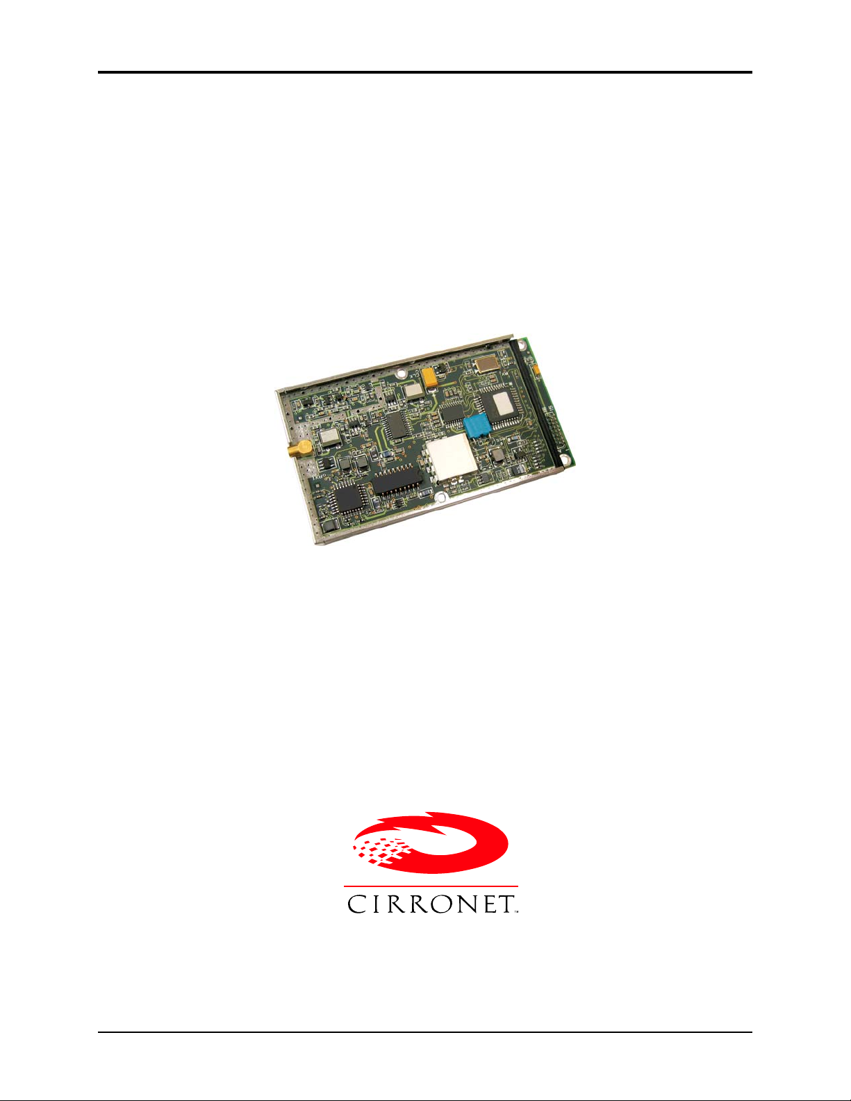
WIT2492
WIT2492
2.4GHz Spread Spectrum Wireless Industrial Transceiver
Integration Guide
3079 Premiere Pkwy Ste 140
Duluth, Georgia 30097
www.cirronet.com
RFM/Cirronet Inc 1 WIT2492
+1 (678) 684-2000
Page 3

WIT2492
Important Regulatory Information
RFM/Cirronet WIT2492 - FCC ID: HSW-2492, IC ID: 4492A-2492
Note: This unit has been tested and found to comply with the limits for a Class B digital device,
pursuant to part 15 of the FCC Rules. These limits are designed to provide reasonable protection
against harmful interference when the equipment is operated in a commercial environment. This
equipment generates, uses, and can radiate radio frequency energy and, if not installed and used
in accordance with the instruction manual, may cause harmful interference to radio
communications. Operation of this equipment in a residential area is likely to cause harmful
interference in which case the user will be required to correct the interference at their expense.
FCC s MPE Requirements
Information to user/installer regarding FCC s Maximum Permissible Exposure (MPE) limits.
Notice to users/installers using the following fixed antennas, with Cirronet RF products:
Cushcraft 15dBi Yagi,
Mobile Mark 14dBi Corner Reflector,
Mobile Mark 9dBi Corner Reflector
Notice to users/installers using the following mobile antennas, with Cirronet RF products:
Mobile Mark 9dBi omni-directional,
MaxRad 5dBi whip,
Cirronet Patch antenna,
Ace 2dBi dipole,
Mobile Mark 2dBi Stub
The field strength radiated by any one of these
antennas, when connected to Cirronet RF
products, may exceed FCC mandated RF
exposure limits. FCC rules require
professional installation of these antennas in
such a way that the general public will not be
closer than 2 m from the radiating aperture of
any of these antennas. End users of these
systems must also be informed that RF
exposure limits may be exceeded if personnel
come closer than 2 m to the apertures of any of
these antennas.
The field strength radiated by any one of these
antennas, when connected to Cirronet RF
products, may exceed FCC mandated RF
exposure limits. FCC rules require professional
installation of these antennas in such a way
that the general public will not be closer than
20 cm from the radiating aperture of any of
these antennas. End users of these systems
must also be informed that RF exposure limits
may be exceeded if personnel come closer
than 20 cm to the apertures of any of these
antennas.
The WIT2492 may be used in Portable applications only under the following conditions:
1) When operated in Remote mode where the transmitted duty cycle less than or equal to
5.6%, the WIT2492 may use any type-approved antenna with up to 6 dBi of gain. Antenna gains
exceeding 6dBi are strictly prohibited.
2) When operated in Base mode where the transmitted duty cycle less than or equal to
12.85%, the WIT2492 may use any type-approved antenna with up to 2 dBi of gain. Antenna gains
exceeding 2dBi are strictly prohibited.
RFM/Cirronet Inc 2 WIT2492
Page 4

WIT2492
Labeling and Notices
Labeling:
A clearly visible label is required on the outside of the user’s (OEM) enclosure stating the following:
”Contains FCC ID: HSW-2492”
”Contains IC: 4492A-2492”
Notices:
WARNING: This device operates under Part 15 of the FCC rules. Any modification to this device, not
expressly authorized by RFM, Inc., may void the user’s authority to operate this device.
FCC NOTICE: This device complies with Part 15 of the FCC rules. Operation is subject to the following
two conditions: (1) this device may not cause harmful interference, and (2) this device must accept any
interference received, including interference that may cause undesired operation.
IC Notice - This device complies with Industry Canada licence-exempt RSS standard(s). Operation is
subject to the following two conditions: (1) this device may not cause interference, and (2) this device
must accept any interference, including interference that may cause undesired operation of the device.
Under Industry Canada regulations, this radio transmitter may only operate using an antenna of a type
and maximum (or lesser) gain approved for the transmitter by Industry Canada. To reduce potential radio
interference to other users, the antenna type and its gain should be so chosen that the equival ent
isotropically radiated power (e.i.r.p.) is not more than that necessary for successful communication.
This radio transmitter, IC: 4492A-2492, has been approved by Industry Canada to operate with the
antenna types listed later in this manual with the maximum permissible gain and required antenna
impedance for each antenna type indicated.
Canadian ICES-003 - This digital apparatus does not exceed the Class B limits for radio noise emissions
from digital apparatus as set out in the radio interference regulations of Industry Canada.
Le present appareil numerique n’emet pas de bruits radioelectriqu es depassant les limites applicables
aux appareils numeriques de Classe B prescrites dans le reglement sur le brouillage radioelectrique
edicte par Industrie Canada.
Canadian Department of Communications Industry Canada (IC) Notice
Canadian Department of Communications Industry Canada (IC) Notice
This apparatus complies with Health Canada’s Safety Code 6 / IC RSS 102.
"To prevent radio interference to the licensed service, this device is intended to be
operated indoors and away from windows to provide maximum shielding. Equipment (or
its transmit antenna) that is installed outdoors may be subject to licensing."
RFM/Cirronet Inc 3 WIT2492
Page 5

1. INTRODUCTION
The WIT2492 radio transceiver provides reliable wireless connectivity for either
point-to-point or multipoint applications. Frequency hopping spread spectrum
technology ensures maximum resistance to noise and multipath fading and robustness in
the presence of interfering signals, while operation in the 2.4GHz ISM band allows
license-free use and worldwide compliance. A simple serial interface supports
asynchronous data up to 921600 bps. An on-board 3 KB buffer and an error-correcting
over-the-air protocol provide smooth data flow and simplify the task of integration with
existing applications.
- Multipath fading impervious
frequency hopping technology
with 43 frequency channels
(2401-2475 MHz).
- Supports point-to-point or
multipoint applications.
- Meets FCC rules 15.247 and ETS
300.328 for worldwide licensefree operation.
- Superior range to 802.11 wireless
LAN devices.
- Transparent ARQ protocol
w/3KB buffer ensures data
integrity.
- Built-in data scrambling reduces
possibility of eavesdropping.
- Nonvolatile memory stores
configuration when powered
off.
- Smart power management
features for low current
consumption.
- Dynamic TDMA slot
assignment that maximizes
throughput.
- Digital addressing supports up to
64 networks, with 62 remotes per
network.
- Low power 3.3v CMOS signals
- Simple serial interface handles both
data and control at up to 921600 bps.
- Fast acquisition typically locks to
hopping pattern in 2 seconds or less.
- Selectable 10 mW or 100 mW transmit
power.
- Support for diversity antenna.
WIT2492
RFM/Cirronet Inc 4 WIT2492
Page 6

4. MODEM INTERFACE
t
Electrical connection to the WIT2492 is made
through a 16-pin male header on the modem
module. The signals are 3.3 volt signals and form
an RS-232 style asynchronous serial interface.
The table below provides the connector pinout.
Pin Signal Type Description
1 GND - Signal and chassis ground
2 TXD Input Transmit data. Input for serial data to be transmitted. In Control Mode
3 RXD Output Receive data. Output for received serial data. In Control Mode, also
WIT2492
also used to transmit modem commands to the modem.
carries receive modem status from the modem.
4 Input Configuration selector. Used to switch between Control and Data Modes.
5 Input Request to send. Gates the flow of receive data from the radio to the user
6 SLEEP Input Sleeps/wakes radio transceiver. In sleep mode all radio functions are
7
CFG
RTS
DCD
Normally, CFG will be set for Data Mode. An internal 10K pull-up enables
Data Mode if this signal is left unconnected. Control Mode is also
accessible by transmitting an escape sequence immediately after wake
up or power up.
(0v) 1 = Control Mode
(3.3v) 0 = Data Mode
on or off. In normal operation this signal should be asserted. When
negated, the WIT2492 buffers receive data until RTS is asserted.
(0v) 1 = Receive data (RxD) enabled
(3.3v) 0 = Receive data (RxD) disabled.
disabled consuming less than 50µA. At wake up, any user programmed
configuration settings are refreshed from non-volatile memory, clearing
any temporary settings that may have been set.
(3.3v) 1 = Sleep Radio
(0v) 0 = Wake Radio
Output Data carrier detect. For remotes, indicates the remote has successfully
acquired the hopping pattern of the base station.
(0v) 1 = Carrier detected (synchronized)
(3.3v) 0 = No carrier detected (not synchronized)
8
9 - - Reserved for future use. Do not connect.
10 Input Resets the radio.
11-15 - - Reserved for future use. Do not connect.
16 VCC - Positive supply. Min 3.3 v, 5.0 v nominal, 10.0 v max.
CTS
Rese
Output Clear to send. Used to control transmit flow from the user to the radio.
(0v) 1 = Transmit buffer not full, continue transmitting
(3.3v) 0 = Transmit buffer full, stop transmitting
RFM/Cirronet Inc 2 WIT2492
Page 7

9. APPENDICES
9.1. Technical Specifications
9.1.1 Ordering Information
WIT2492M4 OEM Module, Serial connector pins down - Standard
WIT2492S4 OEM Module, Serial connector pins up
9.1.2. Power Specifications
Vcc Input Range: 3.3v to 10.0v
Operating Temperature Range: -30C to +70C
Current Consumption (Max transmit power, 230.4Kbps I/O)
Mode Remote Base Station
Sleep
Standby
Typical Average
Peak (Tx)
9.1.3. RF Specifications
FCC Certification Part 15.247, no license required
ETSI (European) Certification EN 300.328, no license required
Rated RF Power +18 dBm (+20 dBm effective radiated)
Line-of-site Range 6/10 of a mile w/2dB dipole
Frequency Range 2401 – 2480MHz
Number of Channels 43 US; Canada, France,
Receiver Sensitivity -90dBm
Channel Data Rate 921.6Kbps
IF Adjacent Channel Rejection >55dB
9.1.4. Mechanical Specifications
Weight 35g
Dimensions (including shield) 80.2 x 46.5 x 8.6mm
(refer to section 7.6 for mechanical drawing)
RF Connector:
WIT Huber/Suhner: 85 MMCX 50-0-1
Mating Huber/Suhner: 11 MMCX-50-2-3 (straight)
Huber/Suhner: 16 MMCX-50-2-2 (rt. angle)
Data/Power Connector:
WIT Samtec: DIS5-108-51-L-D
Mating Samtec: CLP-108-02-G-D (PCB mount)
Samtec: FFSD-08 (IDC cable)
WIT2492
50µA N/A
20mA N/A
50mA 80mA
80mA 100mA
RFM/Cirronet Inc 3 WIT2492
Page 8

9.2. Serial Connector Pinouts
Signal
GND 1 5
TXD 2 3
RXD 3 2
CFG 4 RTS 5 7
SLEEP 6 4
DCD 7 1
CTS 8 8
WIT2492M/S4
OEM Pinout
The HN-510 is wired as a DCE device and as such can be connected to DTE devices such
as PCs with a straight-through cable. When connecting a HN-510 to a DTE device, a
“null modem” cable is required. To effect a null modem cable, cross-wire TXD and
RXD and connect ground. The HN-510 can operate with just these three wires
connected. However, as the WIT2492 does not support software flow control, there will
be no flow control in this mode. If the DTE device fails to respond, connect DCD from
the HN-510 to the DTR and RTS inputs to activate the DCE device whenever the
WIT2492 asserts carrier.
When connecting to the WIT2492M/S4, make sure that all of the inputs (TXD, CFG,
RTS and SLEEP) are terminated for proper operation.
9.3. Approved Antennas
The WIT2492M/S4 is designed to ensure that no antenna other than the one fitted shall
be used with the device. The end user must permanently affix the antenna by using an
adhesive on the coupling such as Loctite, or ensure the antenna has a unique coupling.
The table below lists the antennas which can be purchased directly from Cirronet.
Contact Cirronet Technical Support with any questions.
Description Gain Manufacturer Type
15dBi Yagi 15dB Cushcraft Yagi
14dBi Corner Reflector 14dB Mobile Mark Corner Reflector
9dBi Omni-directional 9dB Mobile Mark Dipole (omni)
9dBi Corner Reflector 9dB Mobile Mark Corner Reflector
6dBi Cironnet Patch 6dB Cirronet/RFM Planar Patch
5dBi Whip 5dB MaxRad Dipole (omni)
2dBi Cirronet Patch 2dB Cirronet/RFM Planar Patch
2dBi Stub 2dB Mobile Mark Dipole (omni)
HN-510
DB9
Pinout
WIT2492
Note: The WIT2492M4 is the
standard part number and has
the serial connector pins
pointing down allowing
connection to a mother board
without using a cable.
WIT2492S4 has the serial
connector pins pointing up.
RFM/Cirronet Inc 4 WIT2492
Page 9

9.4. Technical Support
For technical support call RFM/Cirronet at (678) 684-2000 between the hours of
8:30AM and 5:30PM Eastern Time.
WIT2492
RFM/Cirronet Inc 5 WIT2492
Page 10

9.5. Reference Design
DTR
RTS
RS232 Interface
Optional pullups to keep
RT S and DT R ass ert ed
when left unconnected
12
D1
MBR0520L
12
R1
6.8k
12
R2
6.8k
TXD
RXD
CTS
C1
0.22uF
C2
1 uF
VCC 3.3V
WIT2492
U5
26
VCC
28
25
1
3
8
9
11
12
10
7
6
5
16
13
14
15
C1+
C1-
C2+
C2R1IN
R2IN
R3IN
T5OUT
T4OUT
T3OUT
T2OUT
T1OUT
R1OUTB
FORCEON
FORCEOFF
INVA LID
MAX3238
R1OUT
R2OUT
R3OUT
12
+
T5IN
T4IN
T3IN
T2IN
T1IN
GND
V+
V-
27
4
21
20
18
17
19
22
23
24
2
+
C3
1 uF
C4
+
1 uF
12
If using a 5.0V converter use the
fo ll owi ng ci rcu it fo r TXD ,DT R,R TS
TXD_5V
VCC 3.3V
C5
0.1uF
TXD_3.3V
DTR_SLEEP _3.3V
RTS_3.3V
RXD_3.3 V
DCD_3.3VDCD
CTS_3.3V
WIT2410 Interface
R1
1 2
10k
2200
R2
20k
4300
TXD_3.3V
1 2
2000- 2005 Cirronet Inc 6 M-2492-0000 Rev G
Page 11

9.6.1. Mechanical Drawing – WIT2492M4 (Pins Down)
WIT2492
2000- 2005 Cirronet Inc 7 M-2492-0000 Rev G
Page 12

9.6.2. Mechanical Drawing – WIT2492S4 (Pins Up)
WIT2492
2000- 2005 Cirronet Inc 8 M-2492-0000 Rev G
Page 13

10. Warranty
Seller warrants solely to Buyer that the goods delivered hereunder shall be free from
defects in materials and workmanship, when given normal, proper and intended usage, for
twelve (12) months from the date of delivery to Buyer. Seller agrees to repair or replace at
its option and without cost to Buyer all defective goods sold hereunder, provided that
Buyer has given Seller written notice of such warranty claim within such warranty period.
All goods returned to Seller for repair or replacement must be sent freight prepaid to
Seller’s plant, provided that Buyer first obtain from Seller a Return Goods Authorization
before any such return. Seller shall have no obligation to make repairs or replacements
which are required by normal wear and tear, or which result, in whole or in part, from
catastrophe, fault or negligence of Buyer, or from improper or unauthorized use of the
goods, or use of the goods in a manner for which they are not designed, or by causes
external to the goods such as, but not limited to, power failure. No suit or action shall be
brought against Seller more than twelve (12) months after the related cause of action has
occurred. Buyer has not relied and shall not rely on any oral representation regarding the
goods sold hereunder, and any oral representation shall not bind Seller and shall not be a
part of any warranty.
THE PROVISIONS OF THE FOREGOING WARRANTY ARE IN LIEU OF ANY
OTHER WARRANTY, WHETHER EXPRESS OR IMPLIED, WRITTEN OR
ORAL (INCLUDING ANY WARRANTY OR MERCHANT ABILITY OR
FITNESS FOR A PARTICULAR PURPOSE). SELLER’S LIABILITY ARISING
OUT OF THE MANUFACTURE, SALE OR SUPPLYING OF THE GOODS OR
THEIR USE OR DISPOSITION, WHETHER BASED UPON WARRANTY,
CONTRACT, TORT OR OTHERWISE, SHALL NOT EXCEED THE ACTUAL
PURCHASE PRICE PAID BY BUYER FOR THE GOODS. IN NO EVENT
SHALL SELLER BE LIABLE TO BUYER OR ANY OTHER PERSON OR
ENTITY FOR SPECIAL, INCIDENTAL OR CONSEQUENTIAL DAMAGES,
INCLUDING, BUT NOT LIMITED TO, LOSS OF PROFITS, LOSS OF DATA OR
LOSS OF USE DAMAGES ARISING OUT OF THE MANUFACTURE, SALE OR
SUPPLYING OF THE GOODS. THE FOREGOING WARRANTY EXTENDS TO
BUYER ONLY AND SHALL NOT BE APPLICABLE TO ANY OTHER PERSON
OR ENTITY INCLUDING, WITHOUT LIMITATION, CUSTOMERS OF
BUYERS.
WIT2492
2000- 2005 Cirronet Inc 9 M-2492-0000 Rev G
 Loading...