

Murata Electronics North America 2492 Users Guide

FCC Part 15.247
Transceiver Certification
Digital Transmission System with Frequency Hopping Spread Spectrum
Test Report
FCC ID: HSW-2492
FCC Rule Part: 15.247
ACS Report Number: 07-0052-15C
Manufacturer: Cirronet
Model: WIT2492
Integration Guide
5015 B.U. Bowman Drive Buford, GA 30518 USA Voice: 770-831-8048 Fax: 770-831-8598

WIT2492
2.4 GHz Spread Spectrum
Wireless Industrial Transceiver
Preliminary
Integration Guide
3079 Premiere Pkwy Ste 140
Duluth, Georgia 30097
www.cirronet.com
+1 (678) 684-2000

Important Regulatory Information
Cirronet Product FCC ID: HSW-2492
IC 4492A-2492
Note: This u nit has been tested and found to comp ly with the limits for a Class B digital device,
pursuant to part 15 of the FCC Rules. These limits are designed to provide reasonable protection
against harmful interference when t he equipment is operat ed in a commercial environment . This
equipment generates, uses, and can radiate radio frequency energy and, if not installed and used
in accordance with the instruction manual, may cause harmful interference to radio
communications. Operation of this equipment in a residential area is likely to cause harmful
interference in which case the user will be required to correct the interference at their expense.
FCC s MPE Requirements
Information to user/installer regarding FCC s Maximum Permissible Exposure (MPE) limits.
Notice to users/installers using the following fixed antennas, with Cirronet RF products:
Cushcraft 15dBi Yagi,
Mobile Mark 14dBi Corner Reflector,
Mobile Mark 9dBi Corner Reflector
Notice to users/installers using the following mobile antennas, with Cirronet RF products:
Mobile Mark 9dBi omni-directional,
MaxRad 5dBi whip,
Cirronet Patch antenna,
Ace 2dBi dipole,
Mobile Mark 2dBi Stub
Notice to users/installers using the following Portable antennas, with Cirronet RF products:
Ace 2 dBi dipole
Cirronet 2 dBi patch antenna (PA2410)
Cirronet 6 dBi patch antenna (PA240 0)
Cirronet 5 dBi whip antenna (Omni245RCBL)
The field strength radiated by any one of these
antennas, when connected to Cirronet RF
products, may exceed FCC mandated RF
exposure limits. FCC rules require
professional installation of t hese antennas in
such a way that the general public will not be
closer than 2 m from the radiating aperture of
any of these antennas. End users of these
systems must also be informed that RF
exposure limits may be exceeded if personnel
come closer than 2 m to the apertures of any of
these antennas.
The field strength radiated by any one of these
antennas, when connected to Cirronet RF
products, may exceed FCC mandated RF
exposure limits. FCC rules require professional
installation of these antennas in such a way
that the general public will not be closer than
20 cm from the radiating aperture of any of
these antennas. End users of these systems
must also be informed that RF exposure limits
may be exceeded if personnel come closer
than 20 cm to the apertures of any of these
antennas.
The field strength radiated by any one of these
antennas, when connected to Cirronet’s
WIT2492 product, is below FCC mandated RF
exposure limits for distances less than 2.5 cm
or next to the body.

Declaration of Conformity
The WIT2492 to which this declaration relates is in conformity with the essential requirements of the R&TTE directive
1999/5/EC and complies with the following standards and/or other normative documents:
For Interfaces For RLAN Transceiver
EN 55022
EN 55024
Use Within the European Union
The WIT2492 is intended for use within the European Community States and in the following non-European Union States:
Norway & Switzerland
Use of the WIT2492 in France
When used in France, the WIT2492 can only be operated with the France hopping pattern selected. This is accomplished by
setting the pe parameter to 1. Refer to European Union Settings in this manual for details.
Canadian Department of Communications Industry Canada (IC) Notice
Canadian Department of Communications Industry Canada (IC) Notice
This apparatus complies with Health Canada’s Safety Code 6 / IC RSS 102.
"To prevent radio interference to the licensed service, this device is intended to be operated
indoors and away from windows to provide maxi m um shi eldi ng. Equipment (or its transmit
antenna) that is installed outdoors may be subject to licensing."
The term “IC:” before the radio certification number only signifies that Industry Canada technical specifications were
met.
ICES-003
This digital apparatus does not exceed the Class B limits for radio noise emissions from digital
apparatus as set out in the radio interference regulations of Industry Canada.
Le présent appareil numérique n'émet pas de bruits radioélectriques dépassant les limites applicables aux appareils numériques
de Classe B prescrites dans le règlement sur le brouillage radioélectrique édicté par Industrie Canada.
To reduce potential radio interference to other users, the antenna type and its gain should be so chosen that the
equivalent isotropically radiated power (e.i.r.p.) is not more than that permitted for successful communication.
This device has been designed to operate with the antennas listed above, and having a maximum gain of [15] dB.
Antennas not included in this list or having a gain greater than [15] dB are strictly prohibited for use with this device.
The required antenna impedance is [50] ohms.
Changes or modifications to this device not expressly approved by Cirronet could void the user’s authority to
operate the equipment.
Warning! The RLAN transceiver within this device uses a band of frequencies that are not completely harmonized within the
European Community. Before using, please read the European Operation Section of the Products User’s Guide for limitations.
EN 300 328
Warning!

TABLE OF CONTENTS
1. INTRODUCTION......................................................................................................................1
1.1. Why Spread Spectrum?............................................ ... .................................... ... ..................1
1.2. Frequency Hopping vs. Direct Sequence.............................................................................2
2. RADIO OPERATION ...................................................... ... .................................... ..................5
2.1. Synchronization and Registration.......................................................................................5
2.2. Data Transmission...............................................................................................................6
2.2.1. Point-to-Point............................................................................................................6
2.2.2. Point-to-Multipoint....................................................................................................7
2.2.3. Handle Assignment...................................................................................................7
2.2.4. TDMA Operation......................................................................................................8
2.2.5. Full Duplex Communication..................................... .................................... ... ....... 10
2.2.6. Error-free Packet Transmission Using ARQ........................................................... 10
2.3. Modes of Operation ..........................................................................................................11
2.3.1. Control and Data Modes ......................................................................................... 11
2.3.2. Sleep Mode..............................................................................................................11
2.3.3. Low Power Mode and Duty Cycling....................................................................... 12
2.3.4. RF Flow Control Mode.................................... ... .................................... ................12
2.3.5. Co-Existing with 802.11b Networks.......................................................................13
2.3.6. European Union Settings......................................................................................... 13
3. PROTOCOL MODES..............................................................................................................14
Note on Using Protocol Mode 4........................................ .................................... .............16
3.1.1. Data Packet.............................................................................................................. 17
3.1.3. Connect Packet........................................................................................................18
3.1.4. Disconnect Packet (base only, receive only)............................................. ... ..........18
4. MODEM INTERFACE ...........................................................................................................19
4.1. Interfacing to 5 Volt Systems............................................................................................20
4.2. Evaluation Unit and OEM Module Differences ...............................................................20
4.3. Three Wire Operation............................................. ... .................................... ... ................20
4.4. Power-On Reset Requirements......................................................................................... 21
5. MODEM COMMANDS..........................................................................................................22
5.1. Serial Commands..............................................................................................................22
5.2. Network Commands .............................................................. ... ...... ...... ... ...... ... ...... ...... ... .24
5.3. Protocol Commands..........................................................................................................27
5.4. Status Commands..............................................................................................................30
5.5. Memory Commands.............................. ..................................................................... ....... 31
5.6. Modem Command Summary............................................................................................ 32
6. WIT2492 DEVELOPER’S KIT...............................................................................................33
7. WinCOM.....................................................................................................................
.............34
7.1. Starting the program..........................................................................................................36

7.2. Function Keys....................................... ... ...... ... ...... ...... ... ...... ...... ... ...... ...... ... ...... ...... ....... 39
7.3. WinCom Tools..................................................................................................................40
7.4. Script Commands..............................................................................................................42
7.5. Demonstration Procedure..................................................................................................44
8. Troubleshooting.......................................................................................................................45
9. APPENDICES .........................................................................................................................47
9.1. Technical Specifications...................................................................................................47
9.1.1 Ordering Information .................................................. ...... ... ...... ...... ... ...... ...... ... ...... .47
9.1.2. Power Specifications...............................................................................................47
9.1.3. RF Specifications ................................................ ... .................................... ... ..........47
9.1.4. Mechanical Specifications.......................................................................................48
9.2. Serial Connector Pinouts...................................................................................................48
9.3. Approved Antennas...........................................................................................................49
9.4. Technical Support.............................................................................................................49
9.5. Reference Design..............................................................................................................50
9.6.1. Mechanical Drawing – WIT2492M4 (Pins Down)........................................................51
9.6.2. Mechanical Drawing – WIT2492S4 (Pins Up)................................................. ... .......... 52
10. Warranty.................................................................................................................................53
OEM Installation Compliance Labeling
The WIT2492 module transmitter must be labeled with its own FCC ID number, and, if the FCC ID is not
visible when the module is installed inside another device, then the outside of the device into which the
module is installed must also display a label referring to the enclosed module.
This exterior label can use wording such as the following:
“Contains Transmitter Module FCC ID: HSW-2492” or
“Contains FCC ID: HSW-2492”
Any similar wording that expresses the same meaning may be used. The Grantee may eith er provide such
a label, an example of which must be included in the application for equipment authorization , or, must
provide adequate instructions along with the module which explain this requirement. In the latter case, a
copy of these instructions must be included in the application for equipment authorization.
The antenna connections from the module to the certain antennas approved with this device are not unique
and require Professional installation.

1. INTRODUCTION
The WIT2492 radio transceiver provides reliable wireless connectivity for either
point-to-point or multipoint applications. Frequency hopping spread spectrum
technology ensures maximum resistance to noise and multipath fading and robustness in
the presence of interfering signals, while operation in the 2.4GHz ISM band allows
license-free use and worldwide compliance. A simple serial interface supports
asynchronous data up to 230400 bps. An on-board 3 KB buffer and an error-correcting
over-the-air protocol provide smooth data flow and simplify the task of integration with
existing applications.
- Frequency hopping technology
with 43 frequency channels
(2400-2483.5 MHz).
- Supports point-to-point or
multipoint applications.
- Meets FCC rules DTS and ETS
300.328 for worldwide licensefree operation.
- Superior range to 802.11 wireless
LAN devices.
- Transparent ARQ protocol
w/3KB buffer ensures data
integrity.
- Digital addressing supports up to
64 networks, with 62 remotes per
network.
- Low power 3.3v CMOS signals
1.1. Why Spread Spect r um?
The radio transmission channel is very hostile, corrupted by noise, path loss and
interfering transmissions from other radios. Even in a pure interference-free
environment, radio performance faces serious degradation through a phenomenon
known as multipath fading. Multipath fading results when two or more reflected
rays of the transmitted signal arrive at the receiving antenna with opposing phase,
thereby partially or completely canceling the desired signal. This is a problem
particularly prevalent in indoor installations. In the frequency domain, a multipath
fade can be described as a frequency-selective notch that
- Simple serial interface handles
both data and control at up to
230400 bps.
- Fast acquisition typically locks
to hopping pattern in 2 seconds
or less.
- Selectable 10 mW or 100 mW
transmit power.
- Built-in data scrambling reduces
possibility of eavesdropping.
- Nonvolatile memory stores
configuration when powered
off.
- Smart power management
features for low curren t
consumption.
- Dynamic TDMA slot
assignment that maximizes
throughput.
shifts in location and
WIT2492
© 2000- 2007 Cirronet™ Inc 1 M-2492-0000 Rev G1

WIT2492
intensity over time as reflections change due to motion of the radio or objects within
its range. At any given time, multipath fades will typically occupy 1% - 2% of the
2.4 GHz band. This means that from a probabilistic viewpoint, a conventional radio
system faces a 1% - 2% chance of signal impairment at any given time due to
multipath.
Spread spectrum reduces the vulnerability of a radio system to interference from
both jammers and multipath fading by distributing the transmitted signal over a
larger region of the frequency band than would otherwise be necessary to send the
information. This allows the signal to be reconstructed even though part of it may be
lost or corrupted in transit.
Figure 1
Narrowband vs. spread spectrum in the presence of interference
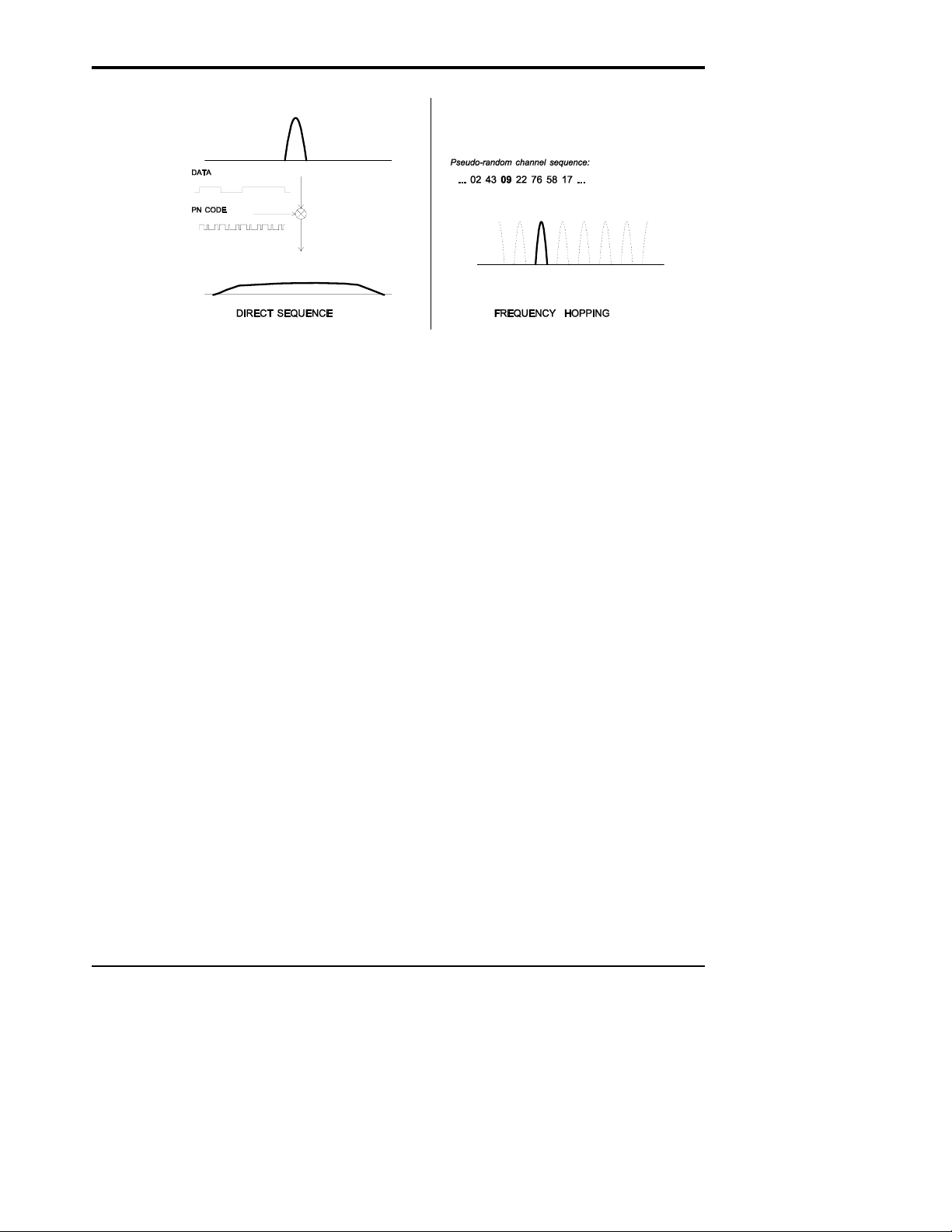
1.2. Frequency Hopping vs. Direct Sequence
The two primary approaches to spread spectrum are direct sequence (DS) and
frequency hopping (FH), either of which can generally be adapted to a given
application. Direct sequence spread spectrum is produced by multiplying the
transmitted data stream by a much faster, noise-like repeating pattern. The ratio by
which this modulating pattern exceeds the bit rate of the baseband data is called the
processing gain, and is equal to the amount of rejection the system affords against
narrowband interference from multipath and jammers. Transmitting the data signal
as usual, but varying the carrier frequency rapidly according to a pseudo-random
pattern over a broad range of channels produces a frequency hopping spectrum
system.
© 2000- 2007 Cirronet™ Inc 2 M-2492-0000 Rev G1
WIT2492
Figure 2
Forms of spread spectrum
One disadvantage of direct sequence systems is that due to spectrum constraints and
the design difficulties of broadband receivers, they generally employ only a minimal
amount of spreading (typically no more than the minimum required by the regulating
agencies). For this reason, the ability of DS systems to overcome fading and in-band
jammers is relatively weak. By contrast, FH systems are capable of probing the
entire band if necessary to find a channel free of interference. Essentially, this
means that a FH system will degrade gracefully as the channel gets noisier while a
DS system may exhibit uneven coverage or work well until a certain point and then
give out completely.
Because it offers greater immunity to interfering signals, FH is often the preferred
choice for co-located systems. Since direct sequence signals are very wide, they
tend to offer few non-overlapping channels, whereas multiple hoppers may
interleave with less interference. Frequency hopping does carry some disadvantage
in that as the transmitter cycles through the hopping pattern it is nearly certain to
visit a few blocked channels where no data can be sent. If these channels are the
same from trip to trip, they can be memorized and avoided; unfortunately, this is
generally not the case, as it may take several seconds to completely cover the hop
sequence during which time the multipath delay profile may have changed
substantially. To ensure seamless operation throughout these outages, a hopping
radio must be capable of buffering its data until a clear channel can be found. A
second consideration of frequency hopping systems is that they require an initial
acquisition period during which the receiver must lock on to the moving carrier of
the transmitter before any data can be sent, which typically takes several seconds. In
summary, frequency hopping systems generally feature greater coverage and channel
utilization than comparable direc t sequence systems. Of course, other
implementation factors such as size, cost, power consumption and ease of
implementation must also be considered before a final radio design choice can be
made.
© 2000- 2007 Cirronet™ Inc 3 M-2492-0000 Rev G1

WIT2492
As an additional benefit, RF spectrum has been set aside at 2.4 GHz in most
countries (including the U.S.) for the purpose of allowing compliant spread spectrum
systems to operate freely without the requirement of a site license. This regulatory
convenience alone has been a large motivation for the industry-wide move toward
spread spectrum.
© 2000- 2007 Cirronet™ Inc 4 M-2492-0000 Rev G1

2. RADIO OPERATION
2.1. Synchronization and Registration
As discussed above, frequency hopping radios periodically change the frequency at
which they transmit. In order for the other radios in the network to receive the
transmission, they must be listening to the frequency over which the current transmission
is being sent. To do this, all the radios in the net must be synchronized and must be set to
the same hopping pattern.
In point-to-point or point-to-multipoint arrangements, one radio module is designated as
the base station. All other radios are designated remotes. One of the responsibilities of
the base station is to transmit a synchronization signal to the remotes to allow them to
synchronize with the base station. Since the remotes know the hopping pattern, once they
are synchronized with the base station, they know which frequency to hop to and when.
Every time the base station hops to a different frequency, it immediately transmits a
synchronizing signal.
When a remote is powered on, it rapidly scans the frequency band for the synchronizing
signal. Since the base station is transmitting over 43 frequencies and the remote is
scanning 43 frequencies, it can take several seconds for a remote to synch up with the
base station.
Once a remote has synchronized with th e base station, it must request registration from
the base station. The registration process identifies to the base station the remotes from
which transmissions will be received and not discarded. Registration also allows tracking
of remotes entering and leaving the network. The base station builds a table of serial
numbers of registered remotes. To improve efficiency, the 24-bit remote serial number is
assigned a 6-bit “handle” number. Two of these are reserved for system use, thus each
base station can register 62 separate remotes. This handle is how user applications will
know the remotes. Note that if a remote leaves the coverage area and then re-enters, it
may be assign ed a different handle.
To detect if a remote has gone offline or out of range, the registration must be “renewed”
once every 256 hops. Registration is completely automatic and requires no user
application intervention. When the remote is registered, it will receive several network
parameters from the base. This allows the base to automatically update these network
parameters in the remotes over the air. Once a parameter has been changed in the base, it
is automatically changed in the remotes. The parameters automatically changed are hop
duration and the duty cycle.
At the beginning of each hop, the base station transmits a synchronizing signal. After the
synchronizing signal has been sent, the base will transmit any data in its buffer unless
data transmit delay has been set. The data transmit delay parameter allows for the
transmission of groups of continuous data in transparent mode (protocol mode 0). The
amount of data that the base station can transmit per hop is determined by the base slot
WIT2492
© 2000- 2007 Cirronet™ Inc 5 M-2492-0000 Rev G1

size parameter. The maximum amount of data sent by a base station per hop is 208 bytes.
If there is no data to be sent, the base station will not transmit until the next frequency.
The operation for remotes is similar to the base station without the synchronizing signal.
The amount of data a remote can send on one hop is dependent upon the hop duration,
the base slot size and the number of registered remotes. 212 bytes per hop is the
maximum data length a remote can transmit per hop, subject to limitations imposed by
the hop duration, the base slot size and the number of registered remotes. A detailed
explanation of this relationship is provided in Section 2.2.3. Minimum data length and
data transmit delay operate the same as with the base station.
Except for the registration process which occurs only when a remote logs onto the
network, the whole procedure is repeated on every frequency hop. Refer to the section
on Modem Commands for complete details on parameters affecting the transmission of
data.
2.2. Data Transmission
The WIT2492 supports two network configurations: point-to-point and point-tomultipoint. In a point-to-point network, one radio is set up as the base station and the
other radio is set up as a remote. In a point-to-multipoint network, a star topology is used
with the radio set up as a base station acting as the central communications point and all
other radios in the network set up as remotes. In this configuration, all communications
take place betw ee n the base station an d a n y one of the remotes . Remotes cannot
communicate directly with each other. It should be noted that point-to-point mode is a
subset of point-to-multipoint mode and therefore there is no need to specify one mode or
the other.
2.2.1. Point-to-Point
In point-to-point mode, unless data transmit delay or minimum data length have been set,
the base station will transmit whatever data is in its bu ffer limited to 208 bytes or as
limited by the base slot size. If the base station has more data than can be sent on one
hop, the remaining data will be sent on subsequent hops. In addition to the data, the base
station adds some information to the transmission over the RF link. It adds the address of
the remote to which it is transmitting, even though in a point-to-point mode there is only
one remote. It also adds a sequence number to identify the transmission to the remote.
This is needed in the case of acknowledging successful transmissions and retransmitting
unsuccessful transmissions. Also added is a 24-bit CRC to allow the base to check the
received transmission for errors. When the remote receives the transmission, it will
acknowledge the transmission if it was received without errors. If no acknowledgment is
received, the base station will retransmit the same data on the next frequency hop.
In point-to-point mode, a remote will transmit whatever data is in its buffer up to the limit
of its maximum data length. If desired, minimum data length and data transmit delay can
WIT2492
© 2000- 2007 Cirronet™ Inc 6 M-2492-0000 Rev G1

also be set, which force the remote to wait until a certain amount of data is available or
the specified delay is exceeded before transmitting. If the remote has more data than can
be sent on one hop, it will send as much data as possible as a packet, adding its own
address, a packet sequence number and 24-bit CRC. These additional bytes are
transparent to the user application if the protocol mode is 00 (which is the default). In the
event a remote has more data to send, the data will be sent on subsequent hops. If the
transmission is received by the base station without errors, the base station will
acknowledge the transmission. If the remote does not receive an acknowledgment, it will
retransmit the data on the next frequency hop. To the user application, acknowledgments
and retransmissions all take place behind the scenes without the need for user
intervention.
The WIT2492 has a point-to-point direct mode which fixes the remote radio’s handle at
30H. This mode is recommended for point-to-point applications, especially if the remote
is likely to periodically leave and re-enter the coverage area of the base. See the section
on Network Commands for details of this mod e.
2.2.2. Point-to-Multipoint
In point-to-multipoint mode, data sent from the user application to the base station must
be packetized by the user application unless the remote device can distinguish between
transmissions intended for it and transmissions intended for other remote devices. This is
necessary to identify the remote to which the base station should send data. When the
user packet is received by the remote, if the remote is in transparent mode (protocol mode
0), the packetization bytes are stripped by the remote. In this instance the remote host
receives just data. If the remote is not in transparent mode, the remote ho st will receive
the appropriate packet header as specified by the remote’s protocol mode. Refer to the
section Protocol Modes for details on the various packet formats.
When a remote sends data to a base station in point-to-multipoint mode, the remote host
does not need to perform any packetization of the data. Remotes can operate in
transparent mode even though the base is operating in a packet mode. The remote will
add address, sequence and CRC bytes as in the point-to-point mode. When the base
station receives the data, the base station will add packetization header bytes according to
its protocol mode se tting.
2.2.3. Handle Assi gnment
Handles are used to reduce overhead by not sending the unique 24-bit serial number ID
of a remote when sending or receiving data. The use of the various protocol modes causes
the base radio to issue CONNECT packets when a new remote registers with the base. In
addition to indicating the presence of a new remote, the CONNECT packets provide the
current relationship between remote serial numbers and handles.
WIT2492
© 2000- 2007 Cirronet™ Inc 7 M-2492-0000 Rev G1

WIT2492
When a remote links to a base and requests registration, it requests by default that it be
assigned handle 30H. This default request can be changed by the Set Default Handle
command. If that handle is not currently in use by another remo te, the base will assign
that handle to the remote. If the requested handle is already in use by another remote, the
base will assign the next higher handle that is available. Thus, if a remote requests handle
30H and that handle is already assigned, the base will assign the remote handle 31H if
that is available. If 31H is already assigned, th e base will assign handle 32H is that is
available and so on.
When a remote leaves the coverage area of the base or otherwise loses link, e.g. the
remote was turned off or put into sleep mode, the base detects this event when the remote
does not renew its registration within 255 hops. With the default setting of 10msec per
hop, this could be as along as 2.55 seconds. If within this time the remote re-establishes
link with the base, the previous handle assigned to this remote will still be marked active
in the base radio. Thus the remote will be assigned a new handle. If the base radio is in
one of the protocol modes, a new CONNECT packet will be issued indicating the current
handle assigned to the remote. The remote is identified by the serial number that is
contained in the CONNECT packet.
If the radio is to be used in a point-to-point mode where there is only one b ase and one
remote, using the point-to-point mode command of the radios will override this handle
mechanism and always assign the remote the same handle.
2.2.4. TDMA Operation
For applications needing guaranteed bandwidth availability, the TDMA operation of the
WIT2492 can meet this requirement. In the WIT2492 TDMA scheme, each remote has
an assigned time slot during which it can transmit. The base station time slot is set
independently of the remote time slots through the Set Base Slot Size command. The
base station assigns each remote a time slot and informs the remotes of the size of the
time slot. All remote time slots are the same size that is determined by the number of
remotes registered with the base station. The slot size is a dynamic variable that changes
as the number of registered remotes changes. The remotes are continually updated with
the time slot size. This approach continually maximizes the data throughput. The base
station divides the amount of time available per hop by the number of registered remotes
up to a maximum of 16 times slots per hop. If the number of registered remotes is greater
than 16, the time slots will be spread across the required number of hops. For networks
with more than 16 possible remotes, the Set Duty Cycle command must be used to specify
a duty cycle -- the number of hops over which the time slots must be spread. For 1 to 16
remotes, no duty cycle is required; for 17 to 32 remotes a duty cycle of at least ½ is
required; and for 33 to 62 remotes a duty cycle of ¼ or more is necessary. An added
benefit of using the power save mode to set a duty cycle is improved average current
consumption efficiency. Refer to the Status Commands section for details of this
command.
© 2000- 2007 Cirronet™ Inc 8 M-2492-0000 Rev G1

WIT2492
7.36
µ
s
When setting up a network, keep in mind that ti me slot length, maximum packet size and
hop duration are all interrelated. The hop duration parameter will determine the time slot
size and the maximum amount of data that can be transmitted per hop by the remotes.
There is a hard limit of the absolute maximum amount of data that can be sent on any
given hop of 212 bytes regardless of any parameters. (Note that this is different than the
208 byte maximum for the base station.) The base station requires 1.7 ms overhead for
tuning, the synchronization signal and parameter updating, as well as a guard time of
500µs between each remote slot. Thus the amount of time allocated per remote slot is
roughly:
hop duration – base slot – 1.7ms - ( # of registered remotes-1)·500µs
( # of registered remotes)
Take for example a network comprised of a base station and 10 remotes. A hop duration
of 10 ms is chosen. We decide that the base station needs t o be able to send up to 32
bytes each hop (equivalent to a capacity for the base of ~ 32 kbps). Counting the 1.7 ms
overhead for the base packet and making use of the fact that our RF rate is 460.8 kbps,
we determine that the base slot requires approximately:
32·8
460.8kbps
+ 1.7 ms = 2.3 ms
Each remote time slot will be:
10 ms – 2.3 ms – (9)·0.5 ms
10
= 0.32 ms
From our RF data rate of 460.8kbps we see that it takes 17.36 µs to send a byte of data,
so each remote will be able to send up to
= 18 bytes of data per hop.
0.32 ms
1
Note that the 18 bytes is the actual number of data bytes that can be sent. If the WIT2492
is using a protocol mode, the packet overhead does not need to be considered. So in this
example, the total capacity per remote would be:
18 bytes
10 ms
= 18 kbps
If we figure a minimum margin of safety for lost packets and retransmissions of about
20%, we see that this would be more than sufficient to support 14.4 kbps of continuous
data per remote. It is also useful to remember that the asynchronous data input to the
WIT2492 is stripped of its start and stop bits during transmission by the radio, yielding a
"bonus" of 10/8 or 25% in additional capacity.
The above calculations are provided as a means of estimating the capacity of a multipoint
WIT2492 network. To determine the precise amount of capacity, you can actually set up
© 2000- 2007 Cirronet™ Inc 9 M-2492-0000 Rev G1

the radio system and then query the maximum data length from one of the remotes in
control mode to discover its exact setting. Divide this nu mber by the hop duration as
above to get the remote's exact capacity.
2.2.5. Full Duplex Communication
From an application perspective, the WIT2492 communicates in full duplex. That is,
both the user application and the remote terminal can be transmitting data without
waiting for the other to finish. At the radio level, the base station and remotes do not
actually transmit at the same time. If they did, the tran smissions would collide. As
discussed earlier, the base station transmits a synchronization signal at the beginning of
each hop followed by a packet of data. After the base station transmission, the remotes
will transmit. Each base station and remote transmission may be just part of a complete
transmission from the user application or the remote terminal. Thus, from an application
perspective, the radios are communicating in full duplex mode since the base station will
receive data from a remote before completing a transmission to the remote.
2.2.6. Error-free Packet Transmission Using ARQ
The radio medium is a hostile environment for data tra nsmission. In a typical office or
factory environment, 1% - 2% of the 2.4GHz frequency b a n d may be unusable at a ny
given time at any given station due to noise, interference or multipath fading. For
narrowband radio systems (and also many spread spectrum radio systems which use
direct sequence spreading), this would imply a loss of contact on average of over 30
seconds per hour per station. The WIT2492 overcomes this problem by hopping rapidly
throughout the band in a pseudo-random pattern. If a message fails to get through on a
particular channel, the WIT2492 simply tries again on the next channel. Even if two
thirds of the band is unusable, the WIT2492 can still communicate reliably.
Data input to the WIT2492 is broken up by the radio into packets. A 24-bit checksum is
attached to each packet to verify that it was correctly received. If the packet is received
correctly, the receiving station sends an acknowledgment, or
station. If the transmitter doesn't receive an
ACK, at the next frequency hop it will attempt
ACK, back to the transmitting
to send the packet again. When ARQ is enabled, the transmitting radio will attempt to
send a packet packet attempts limit times before discarding the packet. A value of
disables ARQ. When it is disabled, any transmission received with errors is discarded. It
is the responsibility of the user application to track missing packets. A second parameter,
ARQ Mode, allows the choice between using ARQ to resend unsuccessful transmissions
or always sending a transmission packet attempts limit times regardless of the success or
failure of any given transmission.
All of this error detection and correction is transparent to the user application. All the
user application sees is error-free data from the modem. However, if the ARQ mode is
disabled, transmissions with errors are discarded, and missing data detection will be the
WIT2492
00H
© 2000- 2007 Cirronet™ Inc 10 M-2492-0000 Rev G1

responsibility of the user app lication. Refer to the Protocol Commands section for
complete details.
2.3. Modes of Operat ion
2.3.1. Control and Data Modes
The WIT2492 has two modes of operation: Control mode and Data mode. When in
Control Mode, the various radio and modem parameters can be modified. When in Data
Mode, only data can be transmitted. The default mode is Data Mode. There are two
ways to enter Control Mode. The first way is to assert the Configure (CFG) pin on the
modem. Upon entering Control Mode, the modem will respond with a > prompt. After
each command is entered, the modem will again respond with a > prompt. As long as the
CFG pin is asserted, data sent to the modem will be inte rpreted as command data. Once
the CFG pin is deasserted, the modem will return to Data Mode.
The second method for entering Control Mode is to send the escape sequence
(all lower case) followed by a carriage return. In the default mode, the escape sequence is
only valid immediately after power up or after deassertion of the Sleep pin on the
modem. The modem will respond in the same way with a
Mode, enter the Exit Modem Cont rol Mode command,
> prompt. To return to Data
z>, or assert and deassert the
Sleep pin. There are three modes for the escape sequence, controlled by the Set Escape
Sequence Mode command,
zc:
zc = 0 Escape sequence disabled
zc = 1 Escape sequence available once at startup (default setting)
zc = 2 Escape sequence available at any time
zc2 mode setting is useful if the user application has a need to change the modem
The
settings "on the fly". In this mode the escape sequence is always enabled and may be sent
at any time after a pause of at least 20ms. The modem will respond in the same way as
when in the default mode. It is necessary to issue the Exit Modem Control Mode
command,
z>, before resuming data transmission. The escape sequence must be
interpreted as data until the last character is received and as such may be transmitted by
the modem to any listening modems.
2.3.2. Sleep Mode
To save power consumption for intermittent transmit applications, the WIT2492 supports
a Sleep Mode. Sleep Mode is entered by asserting the Sleep pin on the modem interface.
While in Sleep Mode, the modem consumes less than 50µA. This mode allows the radio
to be powered off while the terminal device remains powered. After leaving Sleep Mode,
the radio must re-synchronize with the base station and re-register.
WIT2492
:WIT2492
© 2000- 2007 Cirronet™ Inc 11 M-2492-0000 Rev G1

2.3.3. Low Power Mode and Dut y Cycling
To conserve power, WIT2492 remotes power down the receiver and transmitter between
hops when not in use. Base stations must remain active all the time to handle any
transmission from any remote. Remotes can save even more power by enabling the duty
cycle feature. This feature causes a remote to power down for 2
N
1/2
is the duty cycle. Rather than attempting to transmit on every frequency hop when
N
frequency hops where
data is in the transmit buffer, a remote will attempt to transmit only every 2
Roughly speaking, this will proportionately reduce the average power consumption while
increasing average latency. When there are more than 16 remotes being operated, duty
cycling must be enabled since a maximum of 16 time slots is available per hop.
When a remote radio is powered up but is out of range of a base station, it will
continuous scan the frequency bands for the presence of a base radio. During this
scanning the radio can consume up to 80mA of current. A low power seek mode is
available in which the remote radios seek base stations only 50% of the time. Th is will
reduce current consumption by about 50% but will double the time it can take a remote to
link with a base up to 4 seconds.
2.3.4. RF Flow Control Mode
Because of slight differences in baud rates between transmitting and receiving hosts,
when sending large amounts of data (100’s of KB) in one direction in a point-to-point
application, it is possible to overrun the receive buffer of the receiving radio. For example
a nominal 115.2Kbaud at the transmitting radio’s host might really be 115,201 and at the
receiving radio’s host it might be 115,199. This is similar to a situation where the
transmitting radio is sent data at a higher baud rate than the baud rate at which data is
received by the receiving host. To compensate for the variations in nominal baud rates,
the WIT2492 supports an RF flow control mode for point-to-point operation. In this
mode, when the receive buffer of the receiving WIT2492 is close to full, the receiving
WIT2492 stops acknowledging transmissions. The transmitting radio is set to infinite
retries which invokes the RF flow control mode (See Set Packet Attempts Limit in Section
5.3). The receiving radio will not begin acknowledging transmissions from the
transmitting radio until more room in the receive buffer has become available. This will
cause data in the transmit buffer of the transmitting radio to back up. If it backs up to the
point where the transmit buffer fills up, the transmitting radio will deassert CTS stopping
data from the transmitting radio’s host device. Once room is available in the receiving
radio’s buffer, the receiving radio will begin acknowledging transmissions from the
transmitting radio allowing the transmitting radio’s buffer to begin to empty which will
cause the transmitting radio to reassert CTS. Either one or both of the radios in a point-topoint installation can be configured for the RF flow control. If this mode is invoked in a
point-to-multipoint installation, communications with all radios will be stopped when any
one radio’s receive buffer becomes full.
N
hops.
WIT2492
© 2000- 2007 Cirronet™ Inc 12 M-2492-0000 Rev G1
 Loading...