

Page 1
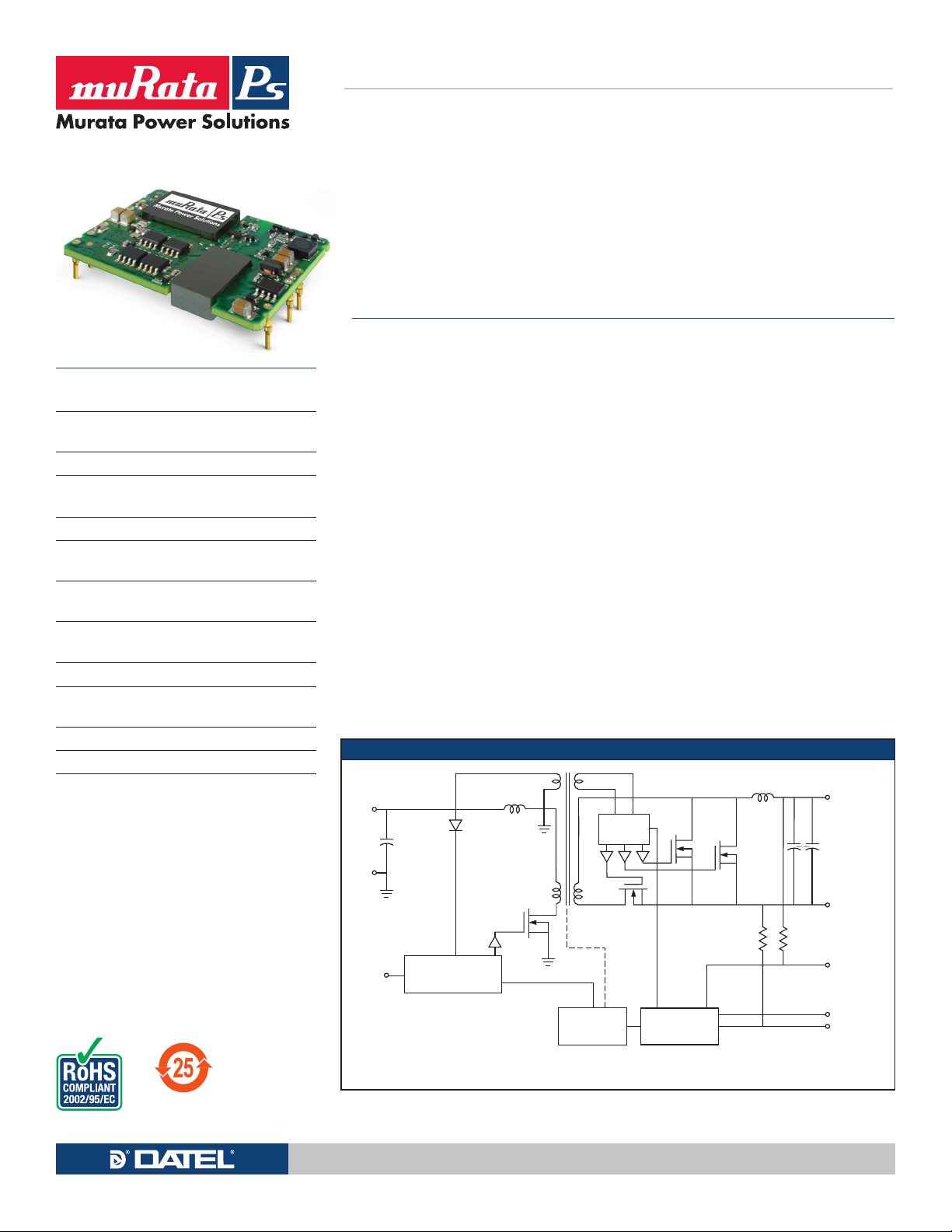
UEI Series
GATE
DRIVE
OPTO
ISOLATION
Control
Reference, trim &
Error Amplifier
+V
IN
+V
OUT
–V
OUT
–V
IN
On/Off
Control
TRIM
–SENSE
+SENSE
ISOLATION
BARRIER
50-60W Isolated Wide-Range DC/DC Converters
Featuring a full 50-60 Watt output in 3.2 square inches of board
area, the UEI series isolated DC/DC converter family offers
efficient regulated DC power for printed circuit board mounting.
Typical unit
FEATURES
n
Small footprint DC/DC converter, ideal for high
current applications
n
Industry standard 1.55" x 2" x 0.4" open frame
package and pinout
n
Wide range input voltages 9-36 and 18-75Vdc
n
Double lead-free assembly and attachment
for RoHS standards
n
2250V Basic isolation (48V models)
n
Up to 50-60W total output power with
overtemperature shutdown
n
High efficiency synchronous rectifier forward
topology
n
Stable no-lead operation with no required
external components
n
Full power –40 to +70°C temperature range
n
UL60950-1, CSA-C22.2 No. 234, EN60950-1
safety approvals
n
Extensive self-protection shut down features
n
RoHS compliant
PRODUCT OVERVIEW
Wide range 4:1 inputs on the 1.55" x 2"x 0.4"
converter are either 9 to 36 Volts DC (Q12
models) or 18 to 75 Volts DC (Q48 models), ideal
for battery-powered and telecom equipment.
Fixed output voltages from 3.3 VDC to 15 VDC are
regulated to within ±0.05% and may be trimmed
within ±10% of nominal output. Applications
include small instruments, computer-based systems, data communications equipment, remote
sensor systems, vehicle and portable electronics.
Full magnetic and optical isolation includes
Basic protection up to 2250 Volts DC. For connection to digital systems, the outputs offer fast
settling to current step loads and tolerance of
higher capacitive loads. Excellent ripple and
noise specifications assure compatibility to
circuits using CPU’s, ASIC’s, programmable logic
and FPGA’s. No minimum load is required. For
systems requiring controlled startup/shutdown,
an external remote On/Off control may use a
SIMPLIFIED SCHEMATIC
switch, transistor or digital logic. Remote Sense
inputs compensate for resistive line drops at high
currents.
A wealth of self-protection features avoid both
converter and external circuit problems. These
include input undervoltage lockout, input overvoltage and overtemperature shutdown. The outputs current limit using the “hiccup” autorestart
technique and the outputs may be short-circuited
indefinitely. Additional features include output
overvoltage and reverse conduction elimination.
The synchronous rectifier forward topology
offers high efficiency for minimal heat buildup
and “no fan” operation. The open frame design
is also available under special quantity order
with an encapsulation shell and thermallyconductive potting compound. This option offers
additional cooling in low-airflow, high temperature applications.
Typical topology is shown.
For full details go to
www.murata-ps.com/rohs
www.murata-ps.com Technical enquiries email: [email protected], tel: +1 508 339 3000
MDC_UEI Series 50-60W.B16 Page 1 of 10
Page 2
UEI Series
50-60W Isolated Wide-Range DC/DC Converters
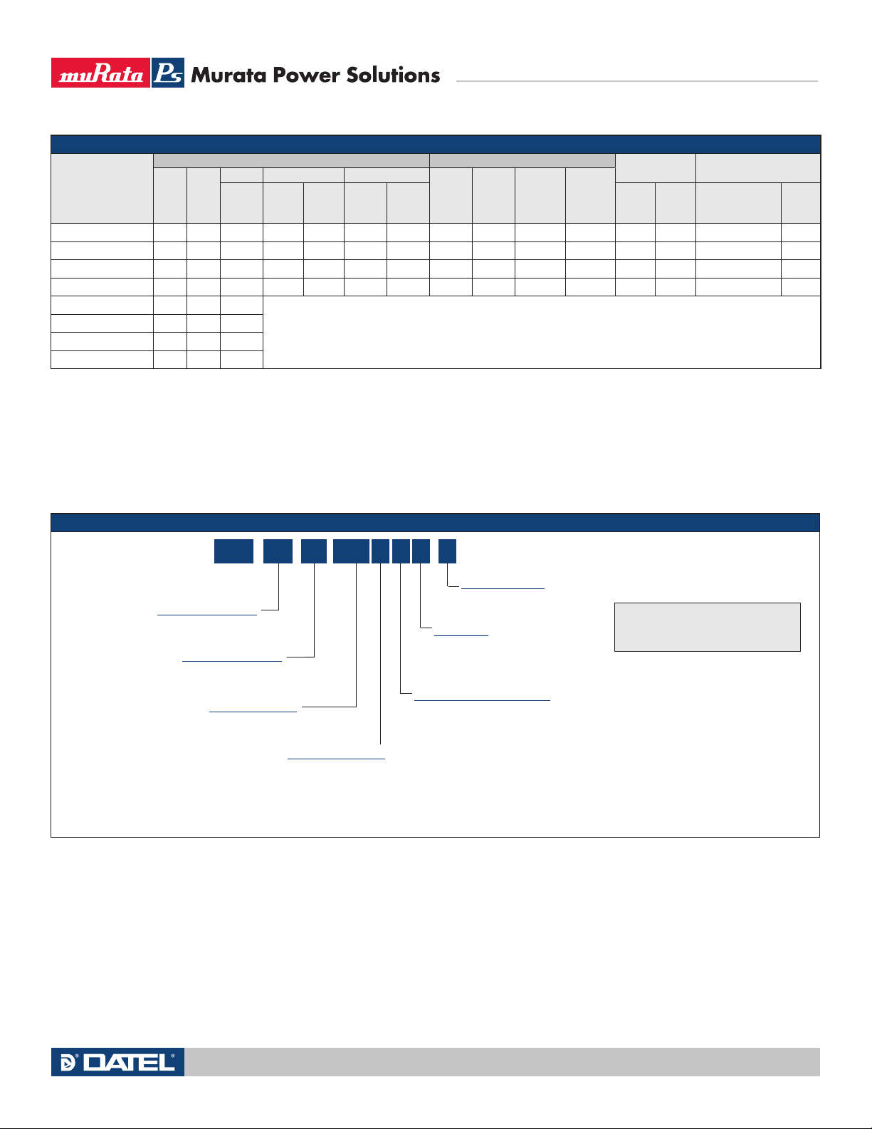
PERFORMANCE SPECIFICATIONS AND ORDERING GUIDE
o u t
V
(V)
Root Model
UEI-3.3/15-Q12PR-C 3.3 15 49.5 15 30 ±0.05% ±0.06% 24 9-36 130 2.33 86.8% 88.5% 1.55x1.95x0.375 P52
UEI-3.3/18-Q48NR-C 3.3 18 59.4 60 125 ±0.075% ±0.2% 48 18-75 130 1.38 87% 89.5% 1.55x1.95x0.375 P52
UEI-5/10-Q12PR-C 5 10 50 35 50 ±0.1% ±0.1% 24 9-36 130 2.31 89% 90% 1.55x1.95x0.375 P52
UEI-5/12-Q48NR-C 5 12 60 70 100 ±0.1% ±0.15% 48 18-75 130 1.37 89.5% 91% 1.55x1.95x0.375 P52
UEI-12/4.2-Q12P-C 12 4.2 50.4
UEI-12/5-Q48N-C 12 5 60
UEI-15/3.3-Q12P-C 15 3.3 49.5
UEI-15/4-Q48N-C 15 4 60
Power R/N (mVp-p) Regulation (Max.)
Io u t
(A)
(W) Typ. Max. Line Load
Output Input
V
IN
Range
Nom.
(V)
Please contact Murata Power Solutions for further information.
(V)
no load
in ,
I
(mA)
in , full
I
load (A)
Efficiency
Min. Typ.
Package
Case (inches) Pinout
These are partial model numbers. Please refer to the full model number structure for complete
ordering part numbers.
These specifications are preliminary. Contact MPS for availability.
All specifications are typical at nominal line voltage and full load, +25 deg.C. unless otherwise
noted. See detailed specifications.
PART NUMBER STRUCTURE
/
UEI -
Nominal Output Voltage
Maximum Rated Output
Current in Amps
Input Voltage Range:
Q12 = 9-36V
Q48 = 18-75V
15
Q12-3.3
P R Z
On/Off Control Polarity:
P = Positive
N = Negative
Positive “P” polarity is standard for Q12 models and optional special
order for Q48 models. Negative “N” polarity is standard for Q48
models and optional special order for Q12 models.
Output capacitors are 1 µF ceramic || 10 µF electrolytic. Input cap is 22 µF, low ESR.
I/O caps are necessary for our test equipment and may not be needed for your application.
Sense input is not included for 12 V
-
C
RoHS-6 compliance
Plastic Case:
Z = Plastic case, optional*
Blank = No plastic case
Sense Inputs (5 Vo u t and lower):
R = Sense included as standard (for 5 Vo u t
and lower models only. 12 Vo u t and higher
models do not offer the sense option.)
Blank = Sense not installed for 5 Vo u t and
lower models. Pins 6 and 9 omitted.
o u t and higher models. Sense is optional for 5 Vo u t and lower.
Note:
Not all model number combinations are
available. Contact Murata Power Solutions.
* Please contact Murata Power Solutions
for availability on teh plastic case models.
Technical enquiries email: [email protected], tel: +1 508 339 3000www.murata-ps.com
MDC_UEI Series 50-60W.B16 Page 2 of 10
Page 3
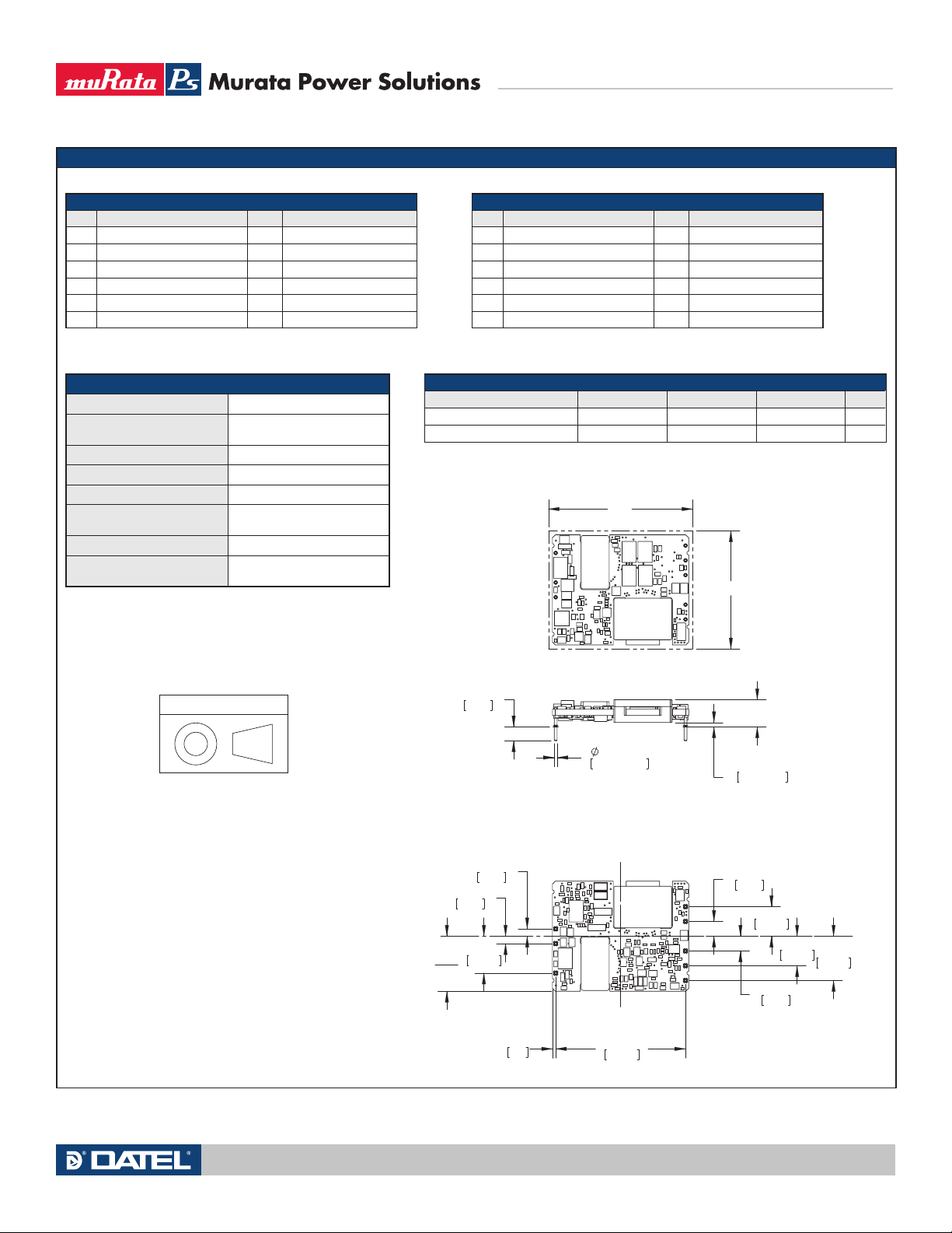
MECHANICAL SPECIFICATIONS
0.64 MIN
‘H’
.025 MIN
CLEARANCE
.188
4.78
‘L’
‘W’
10.16
.400
2.54
.100
1.3
0.05
2.54
.500
.100
2
'W'
12.70
5.08
.400
.200
10.16
5.08
.200
.600
15.24
SIDE VIEW
BOTTOM VIEW
.040±.002 PINS
1.02±0.05
2
TOP VIEW
9
8
7
6
5
4
1
C
L
1
2
4
5
6
7
8
9
C
L
C
L
C
L
1.800
45.72
Third Angle Projection
Dimensions are in inches (mm shown for ref. only).
Components are shown for reference only.
Tolerances (unless otherwise specified):
.XX ± 0.02 (0.5)
.XXX ± 0.010 (0.25)
Angles ± 2˚
UEI Series
50-60W Isolated Wide-Range DC/DC Converters
INPUT/OUTPUT CONNECTIONS, WITH SENSE
Pin Function P52 Pin Function P52
5 +Sense In
1 Positive Input 6 Positive Output
2 Negative Input No pin
3 No pin 7 Negative Output
4 On/Off Control In 8 –Sense In
9 Trim
Important: If sense inputs are not connected to a remote load, connect them
to their respective V
o u t pins at the converter.
PHYSICAL CHARACTERISTICS
Outline dimensions See mechanical specs
Pin material
Copper alloy with gold plate
over nickel underplate
Pin diameter 0.04" (1.016mm)
Pin Finish Gold plate
Weight TBD
Electromagnetic interference
FCC part 15, class B,
EN55022 (may need filter)
Flammability Rating UL 94V-0
Safety
IEC/EN/UL/cUL 60950-1,
CSA-C22.2 No. 60950-1
INPUT/OUTPUT CONNECTIONS, WITHOUT SENSE
Pin Function P51 Pin Function P51
5 No pin
1 Positive Input 6 Positive Output
2 Negative Input No pin
3 No pin 7 Negative Output
4 On/Off Control In 8 No pin
9 Trim
Pins 5 and 8 are omitted for models without sense inputs.
OUTLINE DIMENSIONS
Model Family “H” Height “W” Width “L” Length Case
“Z” Series Plastic Case 0.40 (10.2) 1.60 (40.6) 2.00 (50.8) C78
No Plastic Case (Open Frame) 0.38 (9.5) 1.55 (39.4) 1.95 (49.5) C74
Technical enquiries email: [email protected], tel: +1 508 339 3000www.murata-ps.com
MDC_UEI Series 50-60W.B16 Page 3 of 10
Page 4
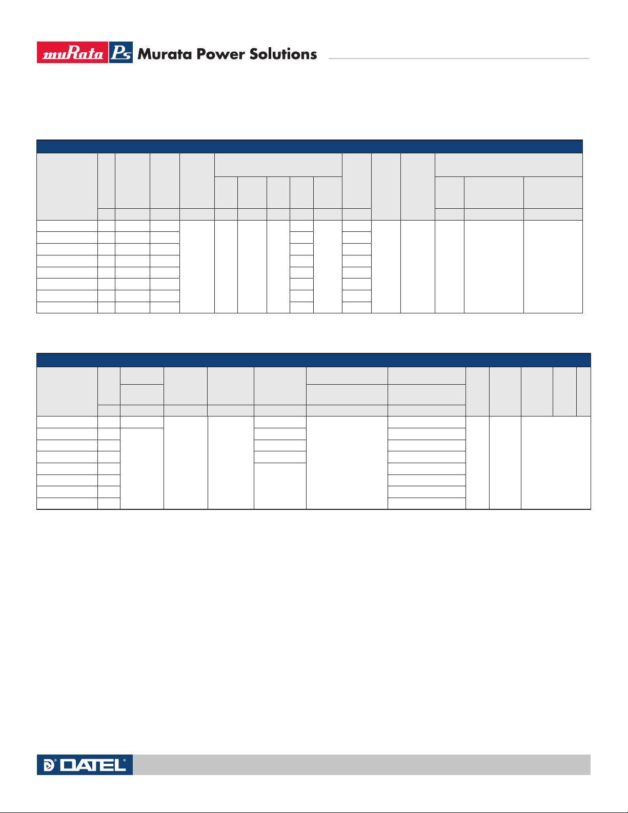
INPUT CHARACTERISTICS
Under-
Start-up
V
Model Family
UEI-3.3/15-Q12
UEI-3.3/18-Q48 48 17.3 16.0 3.71 6
UEI-5/10-Q12 24 9.5 8.5 6.21 12
UEI-5/12-Q48 48 17.3 16.0* 3.70 6
UEI-12/4.2-Q12 TBD 9.5 8.5 6.29 12
UEI-12/5-Q48 TBD 16.7 15.6 3.75 2
UEI-15/3.3-Q12 TBD 8.5 8.0 6.18 4
UEI-15/4-Q48 TBD 16.7 15.6 3.70 6
*At 50% load
in
threshold
V V mA pk-pk A2sec mA mA A mA A mA “P” model suffix “N” model suffix
V
24
9.5 8.5
voltage
Shutdown
Reflected
(back)
Inrush
Ripple
Current
Tran-
2
sient
30 0.05 50 130
Input Current
Output
Short
Circuit
No
Load
Low
Line
6.25
Standby
Mode
1
Recommended
UEI Series
50-60W Isolated Wide-Range DC/DC Converters
Remote On/Off Control
Positive Logic Negative Logic
OFF=Gnd pin or
–0.7 to +1.2V
1
max. ON=open
pin or +10 to
+15V max.
OFF=open pin
or +10 to +15V
max. ON=Gnd
pin or –0.7 to
+1.2V max.
Fuse
12
Internal
Input
Filter
Type
L-C
Reverse
Polarity
Protection
None
- see
notes
On/Off
Current
OUTPUT CHARACTERISTICS
I
o u t
Model Family
UEI-3.3/15-Q12 15
UEI-3.3/18-Q48 18
UEI-5/10-Q12 10 +5 5.9
UEI-5/12-Q48 12 +5 6.4
UEI-12/4.2-Q12 4.2
UEI-12/5-Q48 5 TBD
UEI-15/3.3-Q12 3.3 TBD
UEI-15/4-Q48 4 TBD
Max.
A % of V
o u t
V
Accuracy
50% Load
Adjustment
Range
n o m % of Vn o m % of Vo u t /ºC % of Vo u t max. µF V
±2
±1
±10 ±0.02
Temperature
Coefficient
Remote Sense
Compensation
+5
+5 3.9
Not Available
Capacitive Loading Max.
Low ESR <0.02Ω Max,
resistive load
2,000
Overvoltage
protection
Hiccup auto-start
after fault removal
3.9
16.5
Minimum
No
minimum
load
OV
loading
Magnetic
feedback
method
protection
Ripple/Noise
See ordering guide
8
(20 MHz
bandwidth)
Line/Load
Regulation
Efficiency
Technical enquiries email: [email protected], tel: +1 508 339 3000www.murata-ps.com
MDC_UEI Series 50-60W.B16 Page 4 of 10
Page 5
UEI Series
50-60W Isolated Wide-Range DC/DC Converters
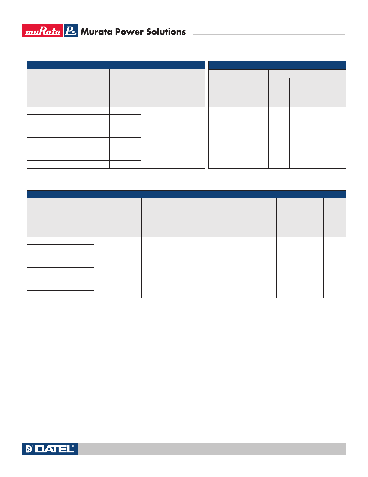
ISOLATION CHARACTERISTICS
Model Family
Input to
Output.
Isolation
Resistance
Min Min
V MΩ pF
UEI-3.3/15-Q12 2000 10
UEI-3.3/18-Q48 2250 10
UEI-5/10-Q12 2000 10
UEI-5/12-Q48 2250 10
UEI-12/4.2-Q12 2000 10
UEI-12/5-Q48 2250 10
UEI-15/3.3-Q12 2000 10
UEI-15/4-Q48 2250 10
MISCELLANEOUS CHARACTERISTICS
Current
Model Family
Limit Inception
98% of V
after warmup
o u t ,
Short
Circuit
Protection
Method
A A Hours ºC ºC ºC
UEI-3.3/15-Q12 20
UEI-3.3/18-Q48 23
UEI-5/10-Q12 14
UEI-5/12-Q48 15.5
UEI-12/4.2-Q12 5.2
UEI-12/5-Q48 6.7
Current
limiting,
hiccup
auto
restart
UEI-15/3.3-Q12 5.3
UEI-15/4-Q48 5.8
Short
Circuit
Current
Isolation
Capacitance
65
Short Circuit
Duration
(output shorted
Isolation Safety
Rating
Basic
insulation
Pre-biased
Calculated
setup
MTBF
to ground)
TBD Continuous Monotonic 2,000,000
DYNAMIC CHARACTERISTICS
Dynamic Load
Response
Model Family
(50-75-50%
load step)
μsec mSec mSec KHz
100 to 2% V
180 to 2% V
All models
100 to 2% V
Operating Temperature
Range
–40 to +85ºC;
with Derating
(see Notes)
Start-up Time
in to Vo u t
V
regulated
(Max.)
o u t
o u t 280
Remote On/Off
to Vo u t
regulated (Max.)
Switching
Frequency
275
50 50
o u t 275
Storage
temperature
range
Thermal
protection/
shutdown
–55 to 125ºC 115
Relative
Humidity,
non-
condensing
To +85ºC/
85%
Specification Notes:
(1) All models are tested and specified with external 1||10 µF output capacitors and a 22 µF external
input capacitor. All capacitors are low ESR types. These capacitors are necessary to accommodate
our test equipment and may not be required to achieve specified performance in your applications. All
models are stable and regulate within spec under no-load conditions.
All specifications are typical unless noted. General conditions for Specifications are +25 deg.C,
Vin=nominal, Vout=nominal, full load. Adequate airflow must be supplied for extended testing under
power.
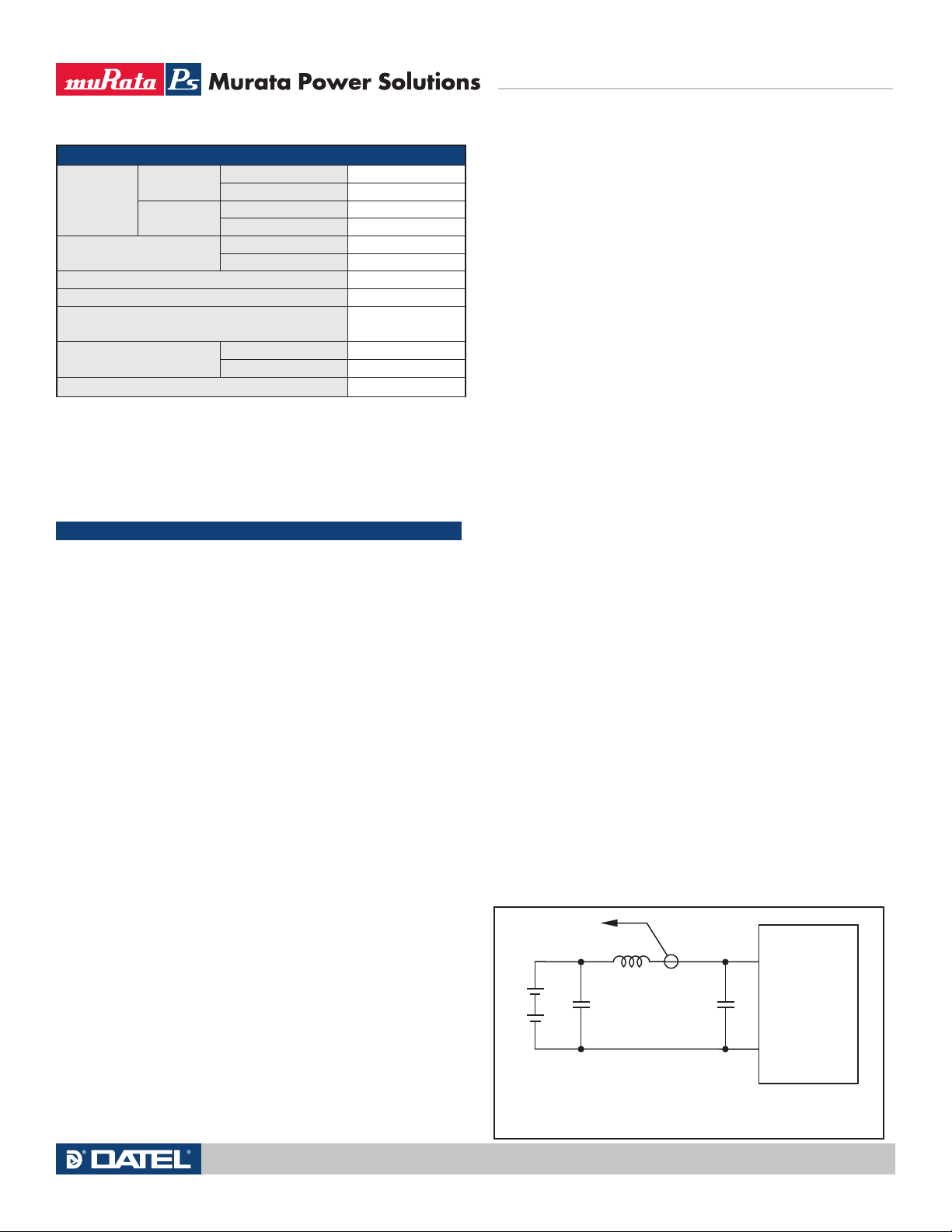
(2) Input Back Ripple Current is tested and specified over a 5 Hz to 20 MHz bandwidth. Input filtering
is Cin=33 µF, 100V, Cbus=220 µF, 100V, Lbus=12 µH.
(3) Note that Maximum Power Derating curves indicate an average current at nominal input voltage.
At higher temperatures and/or lower airflow, the DC/DC converter will tolerate brief full current
outputs if the total RMS current over time does not exceed the Derating curve. All Derating curves
are presented at sea level altitude. Be aware of reduced power dissipation with increasing density
altitude.
(4) Mean Time Before Failure is calculated using the Telcordia (Belcore) SR-332 Method 1, Case 3,
ground fixed conditions, Tpcboard=+25 deg.C, full load, natural air convection.
(5) The On/Off Control is normally selected by a switch or an open collector or open drain transistor.
But it may also be driven with external logic or by applying appropriate external voltages which are
referenced to Input Common and do not exceed the On/Off voltage specifications.
(6) Output current limiting begins when the output voltage degrades approximately 2% from the
selected setting.
(7) The outputs are not intended to sink appreciable reverse current.
(8) Output noise may be further reduced by adding an external filter. Low voltage logic circuits may
have a small voltage margin between logic ZERO and logic ONE, requiring noise suppression. Use only
as much output filtering as needed to achieve your noise requirements. Excessive output capacitance
can retard transient response or possibly cause ringing or instability. Low ESR ceramic capacitors
may degrade dynamic performance. Be sure to thoroughly test your system under full load with all
components installed.
(9) All models are fully operational and meet published specifications, including “cold start” at –40°C.
At full power, the package temperature of all on-board components must not exceed +128°C.
(10) Regulation specifications describe the deviation as the line input voltage or output load current is
varied from a nominal midpoint value to either extreme.
(11) The output overvoltage protection is automatic recovery. The overvoltage may occur either from
internal failure or from an external forcing voltage as in a shared power system.
(12) Output current limit and short circuit protection is non-latching. When the overcurrent fault is
removed, the converter will immediately recover. After an output overcurrent or short circuit, “hiccup”
operation repeatedly attempts to restart the converter with a brief, full-current output. If the overcurrent condition still exists, the restart current will be removed and then tried again. This short current
pulse prevents overheating and damaging the converter. Once the fault is removed, the converter
immediately resumes normal operation.
(13) Do not exceed maximum power specifications when adjusting the output trim.
(14) At zero output current, the output may contain low frequency components which exceed the
ripple specification. The output may be operated indefinitely with no load.
(15) If reverse polarity is accidentally applied to the input, a body diode will become forward biased
and will conduct considerable current. To ensure reverse input protection with full output load, always
connect an external input fuse in series with the +Vin input. Use approximately twice the full input
current rating with nominal input voltage.
CAUTION: This product is not internally fused. To comply with safety agency certifications and to
avoid injury to personnel or equipment, the user must connect an external fast-blow fuse to the input
terminals. See fuse information.
Technical enquiries email: [email protected], tel: +1 508 339 3000www.murata-ps.com
MDC_UEI Series 50-60W.B16 Page 5 of 10
Page 6
UEI Series
C
IN
V
IN
C
BUS
L
BUS
CIN = 33µF, ESR < 700mΩ @ 100kHz
C
BUS
= 220µF, ESR < 100mΩ @ 100kHz
L
BUS
= 12µH
1
2
+INPUT
−INPUT
CURRENT
PROBE
TO
OSCILLOSCOPE
+
–
+
–
50-60W Isolated Wide-Range DC/DC Converters
ABSOLUTE MAXIMUM RATINGS
Q12 models
Input Voltage
Q48 models
On/Off control, referred to –V
Input Reverse Polarity Protection See fuse section
Output Overvoltage, Volts Max. V
Output Current, sustained short circuit
Storage Temperature
Lead Temperature ºC Max. (soldering, 10 seconds) 280
Volts Max. continuous 36
Volts, transient 100mS
Volts Max. continuous
Volts, transient 100mS 100
in
Volts, Min. -0.3
Volts, Max. 15
Range, Min. ºC –55
Max. ºC +125
50
75
o u t nom. +20%
Current-limited,
see specs
Absolute Maximum Ratings
Absolute maximums are stress ratings. Exposure of devices to any of these
conditions may adversely affect long-term reliability. Proper operation under
conditions other than those listed in the Performance/Functional Specifications
is neither implied nor recommended.
APPLICATION NOTES
Input Fusing
Certain applications and/or safety agencies may require fuses at the inputs of
power conversion components. Fuses should also be used when there is the
possibility of sustained input voltage reversal which is not current-limited. We
recommend a time delay fuse installed in the ungrounded input supply line
with a value which is approximately twice the maximum line current, calculated at the lowest input voltage.
The installer must observe all relevant safety standards and regulations. For
safety agency approvals, install the converter in compliance with the end-user
safety standard, i.e. IEC/EN/UL 60950-1.
Start-Up Time
Assuming that the output current is set at the rated maximum, the Vin to Vout StartUp Time (see Specifications) is the time interval between the point when the ramping
input voltage crosses the Start-Up Threshold and the fully loaded regulated output
voltage enters and remains within its specified accuracy band. Actual measured
times will vary with input source impedance, external input capacitance, input voltage slew rate and final value of the input voltage as it appears at the converter.
These converters include a soft start circuit to moderate the duty cycle of its
PWM controller at power up, thereby limiting the input inrush current.
The On/Off Remote Control interval from On command to V
o u t regulated
assumes that the converter already has its input voltage stabilized above the
Start-Up Threshold before the On command. The interval is measured from the
On command until the output enters and remains within its specified accuracy
band. The specification assumes that the output is fully loaded at maximum
rated current. Similar conditions apply to the On to V
o u t regulated specification
such as external load capacitance and soft start circuitry.
Input Source Impedance
These converters will operate to specifications without external components,
assuming that the source voltage has very low impedance and reasonable
input voltage regulation. Since real-world voltage sources have finite impedance, performance is improved by adding external filter components. Sometimes only a small ceramic capacitor is sufficient. Since it is difficult to totally
characterize all applications, some experimentation may be needed. Note that
external input capacitors must accept high speed switching currents.
Because of the switching nature of DC/DC converters, the input of these
converters must be driven from a source with both low AC impedance and
adequate DC input regulation. Performance will degrade with increasing input
inductance. Excessive input inductance may inhibit operation. The DC input
regulation specifies that the input voltage, once operating, must never degrade
below the Shut-Down Threshold under all load conditions. Be sure to use
adequate trace sizes and mount components close to the converter.
Input Reverse-Polarity Protection
If the input voltage polarity is reversed, an internal diode will become forward
biased and likely draw excessive current from the power source. If this source
is not current-limited or the circuit appropriately fused, it could cause permanent damage to the converter.
Input Under-Voltage Shutdown and Start-Up Threshold
Under normal start-up conditions, converters will not begin to regulate properly
until the ramping-up input voltage exceeds and remains at the Start-Up
Threshold Voltage (see Specifications). Once operating, converters will not
turn off until the input voltage drops below the Under-Voltage Shutdown Limit.
Subsequent restart will not occur until the input voltage rises again above the
Start-Up Threshold. This built-in hysteresis prevents any unstable on/off operation at a single input voltage.
Users should be aware however of input sources near the Under-Voltage
Shutdown whose voltage decays as input current is consumed (such as capacitor inputs), the converter shuts off and then restarts as the external capacitor
recharges. Such situations could oscillate. To prevent this, make sure the operating input voltage is well above the UV Shutdown voltage AT ALL TIMES.
I/O Filtering, Input Ripple Current and Output Noise
All models in this converter series are tested and specified for input reflected
ripple current and output noise using designated external input/output components, circuits and layout as shown in the figures below. External input capaci-
in in the figure) serve primarily as energy storage elements, minimizing
tors (C
line voltage variations caused by transient IR drops in the input conductors.
Users should select input capacitors for bulk capacitance (at appropriate
frequencies), low ESR and high RMS ripple current ratings. In the figure below,
Figure 2. Measuring Input Ripple Current
Technical enquiries email: [email protected], tel: +1 508 339 3000www.murata-ps.com
MDC_UEI Series 50-60W.B16 Page 6 of 10
Page 7
UEI Series
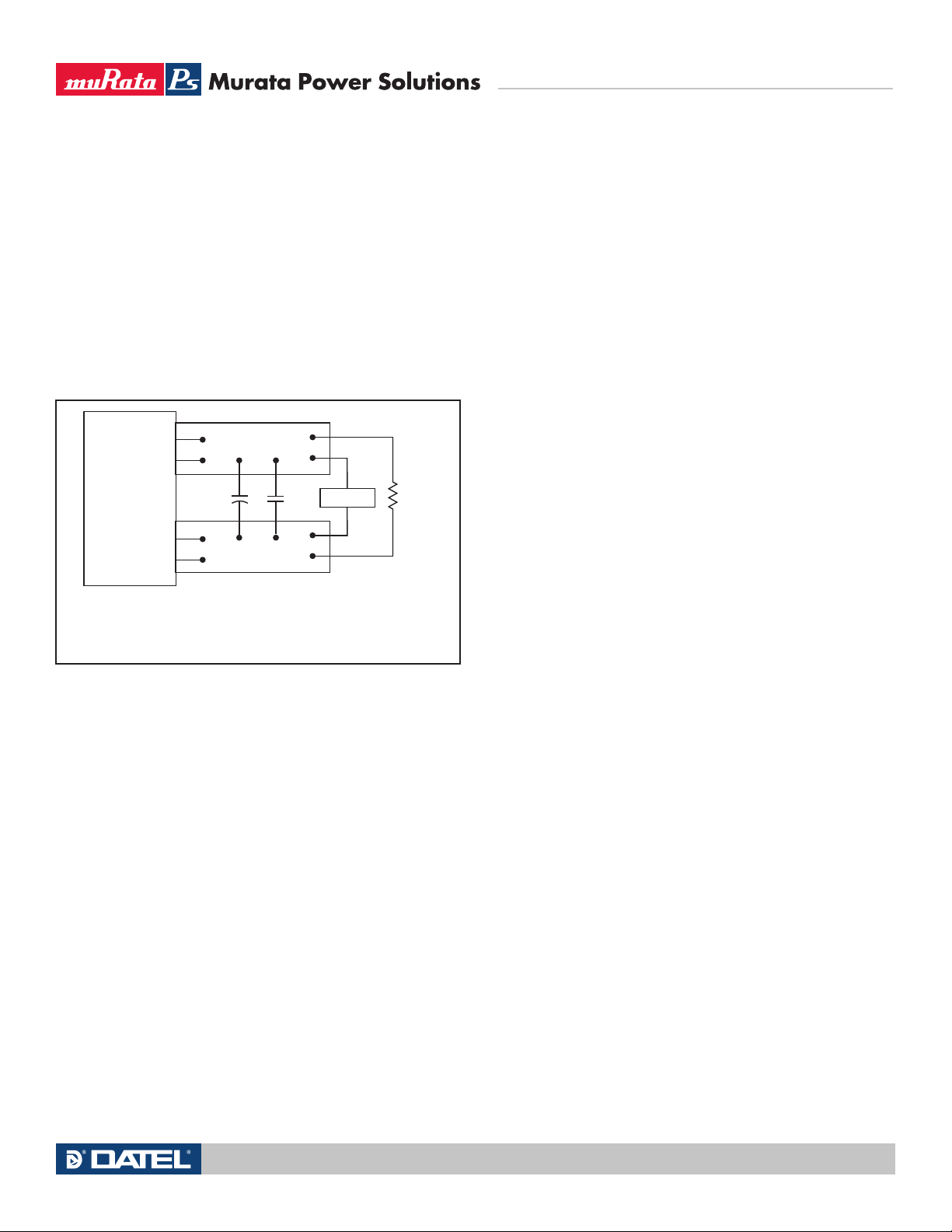
C1
C1 = 0.1µF CERAMIC
C2 = 10µF LOW ES
LOAD 2-3 INCHES (51-76mm) FROM MODULE
C2
R
LOAD
5
6
COPPER STRIP
COPPER STRIP
SCOPE
+OUTPUT
+SENSE
7
8
−SENSE
−OUTPUT
50-60W Isolated Wide-Range DC/DC Converters
the Cb u s and Lb u s components simulate a typical DC voltage bus. Your specific
system configuration may require additional considerations. Please note that the
values of C
in , Lb u s and Cb u s will vary according to the specific converter model.
In critical applications, output ripple and noise (also referred to as periodic
and random deviations or PARD) may be reduced by adding filter elements
such as multiple external capacitors. Be sure to calculate component temperature rise from reflected AC current dissipated inside capacitor ESR. Our
Application Engineers can recommend potential solutions.
In the figure, the two copper strips simulate real-world printed circuit
impedances between the power supply and its load. In order to minimize circuit
errors and standardize tests between units, scope measurements should be
made using BNC connectors or the probe ground should not exceed one half
inch and soldered directly to the fixture.
located adjacent to the switching controller, approximately in the center of the
unit. See the Performance and Functional Specifications.
CAUTION: If you operate too close to the thermal limits, the converter may
shut down suddenly without warning. Be sure to thoroughly test your application to avoid unplanned thermal shutdown.
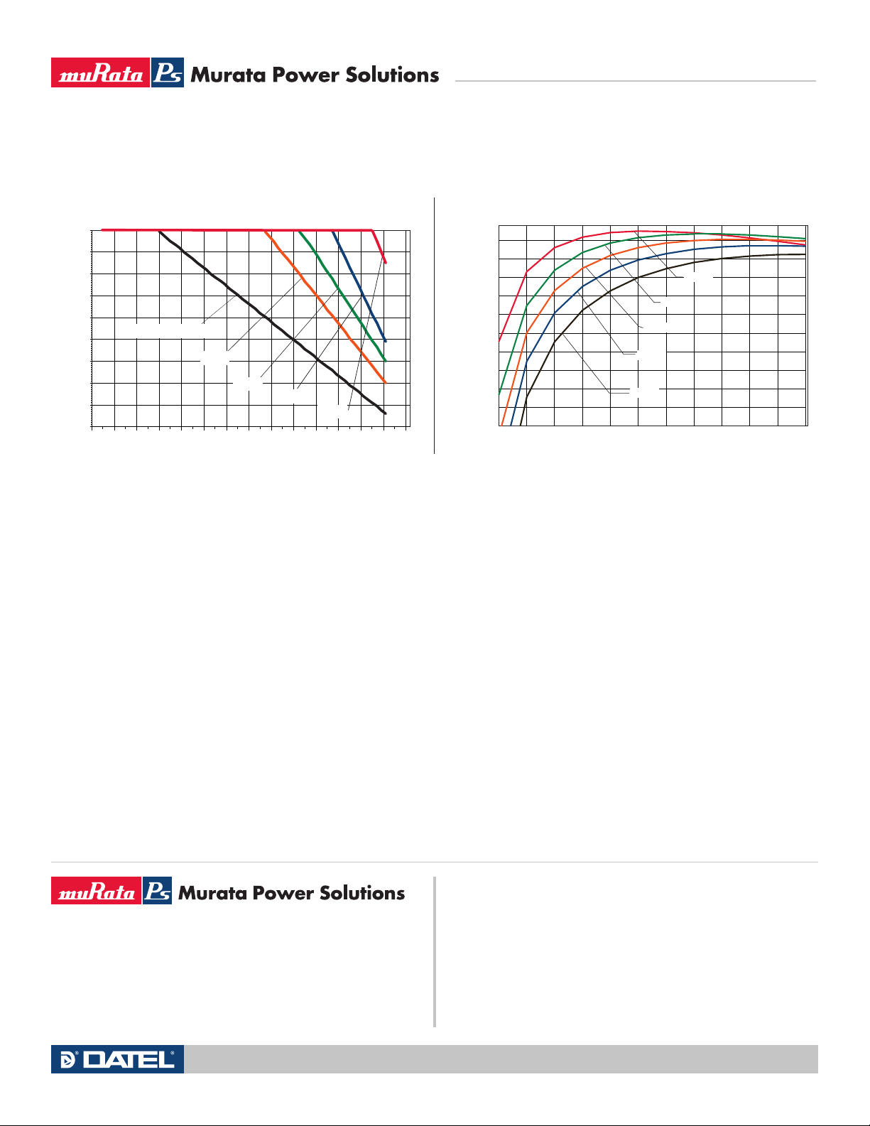
Temperature Derating Curves
The graphs in the next section illustrate typical operation under a variety of conditions. The Derating curves show the maximum continuous ambient air temperature
and decreasing maximum output current which is acceptable under increasing
forced airflow measured in Linear Feet per Minute (“LFM”). Note that these are
AVERAGE measurements. The converter will accept brief increases in temperature
and/or current or reduced airflow as long as the average is not exceeded.
Note that the temperatures are of the ambient airflow, not the converter
itself which is obviously running at higher temperature than the outside air.
Also note that very low flow rates (below about 25 LFM) are similar to “natural
convection”, that is, not using fan-forced airflow.
MPS makes Characterization measurements in a closed cycle wind
tunnel with calibrated airflow. We use both thermocouples and an infrared
camera system to observe thermal performance. As a practical matter, it is
quite difficult to insert an anemometer to precisely measure airflow in most
applications. Sometimes it is possible to estimate the effective airflow if you
thoroughly understand the enclosure geometry, entry/exit orifice areas and the
fan flowrate specifications. If in doubt, contact MPS to discuss placement and
measurement techniques of suggested temperature sensors.
Figure 3 – Measuring Output Ripple and Noise (PARD)
Floating Outputs
Since these are isolated DC/DC converters, their outputs are “floating” with
respect to their input. The essential feature of such isolation is ideal ZERO
CURRENT FLOW between input and output. Real-world converters however do
exhibit tiny leakage currents between input and output (see Specifications).
These leakages consist of both an AC stray capacitance coupling component
and a DC leakage resistance. When using the isolation feature, do not allow
the isolation voltage to exceed specifications. Otherwise the converter may
be damaged. Designers will normally use the negative output (-Output) as
the ground return of the load circuit. You can however use the positive output
(+Output) as the ground return to effectively reverse the output polarity.
Minimum Output Loading Requirements
These converters employ a synchronous rectifier design topology. All models
regulate within specification and are stable under no load to full load conditions.
Operation under no load might however slightly increase output ripple and noise.
Thermal Shutdown
To prevent many over temperature problems and damage, these converters
include thermal shutdown circuitry. If environmental conditions cause the
temperature of the DC/DC’s to rise above the Operating Temperature Range
up to the shutdown temperature, an on-board electronic temperature sensor
will power down the unit. When the temperature decreases below the turn-on
threshold, the converter will automatically restart. There is a small amount of
hysteresis to prevent rapid on/off cycling. The temperature sensor is typically
CAUTION: If you routinely or accidentally exceed these Derating guidelines,
the converter may have an unplanned Over Temperature shut down. Also, these
graphs are all collected at slightly above Sea Level altitude. Be sure to reduce
the derating for higher density altitude.
Output Overvoltage Protection
This converter monitors its output voltage for an over-voltage condition using
an on-board electronic comparator. The signal is optically coupled to the primary side PWM controller. If the output exceeds OVP limits, the sensing circuit
will power down the unit, and the output voltage will decrease. After a time-out
period, the PWM will automatically attempt to restart, causing the output voltage to ramp up to its rated value. It is not necessary to power down and reset
the converter for the this automatic OVP-recovery restart.
If the fault condition persists and the output voltage climbs to excessive
levels, the OVP circuitry will initiate another shutdown cycle. This on/off cycling
is referred to as “hiccup” mode. It safely tests full current rated output voltage
without damaging the converter.
Output Fusing
The converter is extensively protected against current, voltage and temperature
extremes. However your output application circuit may need additional protection.
In the extremely unlikely event of output circuit failure, excessive voltage could be
applied to your circuit. Consider using an appropriate fuse in series with the output.
Output Current Limiting
As soon as the output current increases to approximately 125% to 150% of
its maximum rated value, the DC/DC converter will enter a current-limiting
mode. The output voltage will decrease proportionally with increases in output
Technical enquiries email: [email protected], tel: +1 508 339 3000www.murata-ps.com
MDC_UEI Series 50-60W.B16 Page 7 of 10
Page 8
UEI Series
LOAD
6
8
9
5
7
Contact and PCB resistance
losses due to IR drops
Contact and PCB resistance
losses due to IR drops
+OUTPUT
+SENSE
TRIM
−
SENSE
-OUTPUT
−
INPUT
ON/OFF
CONTROL
+INPUT
2
4
1
Sense Current
I OUT
Sense Return
I OUT Return
LOAD
6
8
7
5
9
5-22
TURNS
2
4
1
7
+OUTPUT
+SENSE
TRIM
−
SENSE
−
OUTPUT
−
INPUT
ON/OFF
CONTROL
+INPUT
LOAD
6
8
9
5
R TRIM DOWN
2
4
1
7
+OUTPUT
+SENSE
TRIM
−
SENSE
−
OUTPUT
−
INPUT
ON/OFF
CONTROL
+INPUT
50-60W Isolated Wide-Range DC/DC Converters
current, thereby maintaining a somewhat constant power output. This is commonly referred to as power limiting.
Current limiting inception is defined as the point at which full power falls
below the rated tolerance. See the Performance/Functional Specifications. Note
particularly that the output current may briefly rise above its rated value. This
enhances reliability and continued operation of your application. If the output
current is too high, the converter will enter the short circuit condition.
Output Short Circuit Condition
When a converter is in current-limit mode, the output voltage will drop as the
output current demand increases. If the output voltage drops too low, the magnetically coupled voltage used to develop primary side voltages will also drop,
thereby shutting down the PWM controller. Following a time-out period, the
PWM will restart, causing the output voltage to begin ramping up to its appropriate value. If the short-circuit condition persists, another shutdown cycle will
initiate. This on/off cycling is called “hiccup mode”. The hiccup cycling reduces
the average output current, thereby preventing excessive internal temperatures. A short circuit can be tolerated indefinitely.
Remote Sense Input
Sense inputs compensate for output voltage inaccuracy delivered at the load.
This is done by correcting voltage drops along the output wiring such as moderate IR drops and the current carrying capacity of PC board etch. Sense inputs
also improve the stability of the converter and load system by optimizing the
control loop phase margin.
Output overvoltage protection is monitored at the output voltage pin, not the
Sense pin. Therefore excessive voltage differences between Vout and Sense
together with trim adjustment of the output can cause the overvoltage protection circuit to activate and shut down the output.
Power derating of the converter is based on the combination of maximum
output current and the highest output voltage. Therefore the designer must insure:
o u t at pins) x (Io u t ) ≤ (Max. rated output power)
(V
Trimming the Output Voltage
The Trim input to the converter allows the user to adjust the output voltage over
the rated trim range (please refer to the Specifications). In the trim equations and
circuit diagrams that follow, trim adjustments use either a trimpot or a single
fixed resistor connected between the Trim input and either the +Sense or –Sense
terminals. (On some converters, an external user-supplied precision DC voltage
may also be used for trimming). Trimming resistors should have a low temperature coefficient (±100 ppm/deg.C or less) and be mounted close to the converter.
Keep leads short. If the trim function is not used, leave the trim unconnected.
With no trim, the converter will exhibit its specified output voltage accuracy.
There are two CAUTION’s to be aware for the Trim input:
CAUTION: To avoid unplanned power down cycles, do not exceed EITHER the
maximum output voltage OR the maximum output power when setting the trim.
Be particularly careful with a trimpot. If the output voltage is excessive, the
Note: The Sense input and power Vout lines are internally connected through
low value resistors to their respective polarities so that the converter can
operate without external connection to the Sense. Nevertheless, if the Sense
function is not used for remote regulation, the user should connect +Sense to
o u t and –Sense to –Vo u t at the converter pins.
+V
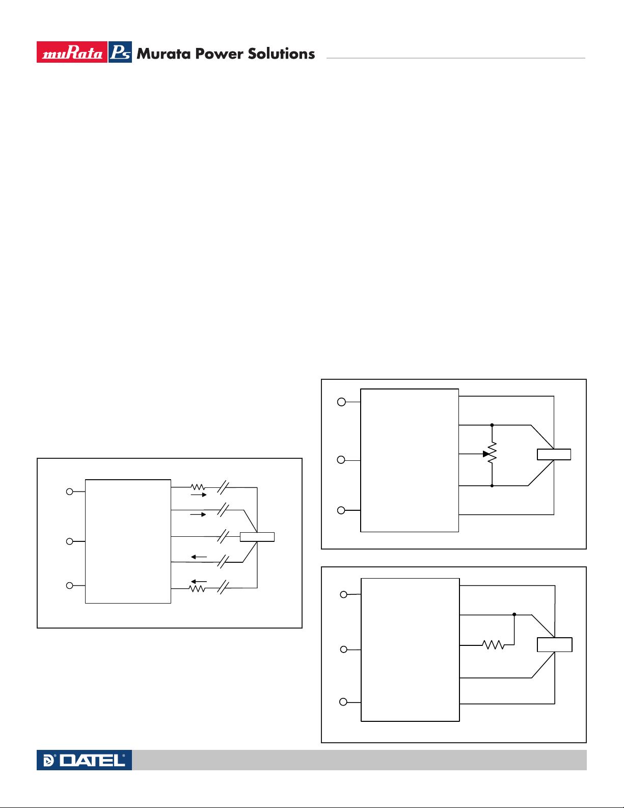
Figure 4 – Remote Sense Circuit Configuration
The remote Sense lines carry very little current. They are also capacitively
coupled to the output lines and therefore are in the feedback control loop to
regulate and stabilize the output. As such, they are not low impedance inputs
and must be treated with care in PC board layouts. Sense lines on the PCB
should run adjacent to DC signals, preferably Ground. In cables and discrete
wiring, use twisted pair, shielded tubing or similar techniques.
Please observe Sense inputs tolerance to avoid improper operation:
o u t (+) –Vo u t (-)] – [ Sense(+) – Sense(-)] ≤ 10% of Vo u t
[V
Figure 5 – Trim adjustments using a trimpot
Figure 6 – Trim adjustments to decrease Output Voltage using a Fixed Resistor
Technical enquiries email: [email protected], tel: +1 508 339 3000www.murata-ps.com
MDC_UEI Series 50-60W.B16 Page 8 of 10
Page 9
UEI Series
ON/OFF
CONTROL
−INPUT
2
4
2
4
1
6
8
9
5
7
+OUTPUT
+SENSE
TRIM
−
SENSE
−
OUTPUT
−
INPUT
ON/OFF
CONTROL
+INPUT
LOAD
R TRIM UP
2
4
ON/OFF
CONTROL
−INPUT
UP
VO – 5
R
T () =
– 2050
12775
5 – V
O
RT () =
– 2050
5110 (Vo - 2.5)
DOWN
UP
VO – 12
R
T () =
– 5110
25000
12 – V
O
RT () =
–5110
10000 (Vo-2.5)
DOWN
UP
DOWN
UEI-5/10-Q12, -5/12-Q48
UEI-12/4.2-Q12, -12/5-Q48
UP
VO – 3.3
R
T () =
– 2050
12775
3.3 – V
O
RT () =
– 2050
5110 (Vo - 2.5)
DOWN
UEI-3.3/15-Q12, -3.3/18-Q48
VO – 15
R
T () =
– 5110
25000
15 – V
O
RT () =
–5110
10000 (Vo-2.5)
UEI-15/3.3-Q12, -Q48
50-60W Isolated Wide-Range DC/DC Converters
OVP circuit may inadvertantly shut down the converter. If the maximum power
is exceeded, the converter may enter current limiting. If the power is exceeded
for an extended period, the converter may overheat and encounter overtemperature shut down.
CAUTION: Be careful of external electrical noise. The Trim input is a senstive
input to the converter’s feedback control loop. Excessive electrical noise may
cause instability or oscillation. Keep external connections short to the Trim
input. Use shielding if needed. Also consider adding a small value ceramic
capacitor between the Trim and –V
Figure 7 – Trim adjustments to increase Output Voltage using a Fixed Resistor
o u t to bypass RF and electrical noise.
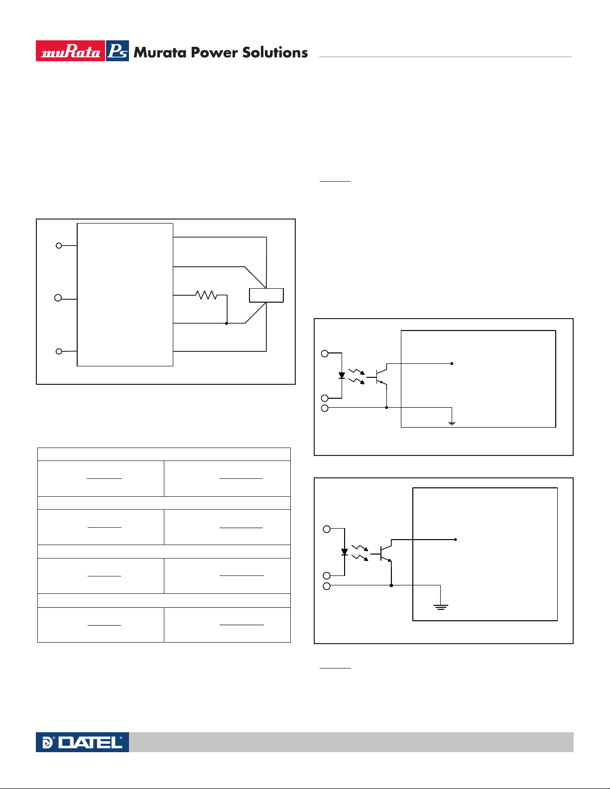
Positive: Standard models are enabled when the On/Off pin is left open or
is pulled high to +V
open pin to rise to +V
in with respect to –Vi n. An internal bias current causes the
in . Some models will also turn on at lower intermediate
voltages (see Specifications). Positive-polarity devices are disabled when the
On/Off is grounded or brought to within a low voltage (see Specifications) with
respect to –V
in .
Negative: Optional negative-polarity devices are on (enabled) when the On/
Off is grounded or brought to within a low voltage (see Specifications) with
respect to –V
pulled high to +15V
in . The device is off (disabled) when the On/Off is left open or is
d c Max. with respect to –Vin .
Dynamic control of the On/Off function should be able to sink appropriate
signal current when brought low and withstand appropriate voltage when
brought high. Be aware too that there is a finite time in milliseconds (see
Specifications) between the time of On/Off Control activation and stable,
regulated output. This time will vary slightly with output load type and current
and input conditions.
There are three CAUTION’s for the On/Off Control:
Trim Equations
Trim Up Trim Down
<Connect trim resistor
between Trim and –Sense>
<Connect trim resistor
between Trim and +Sense>
Where Vo = Desired output voltage. Adjustment accuracy is subject to resistor tolerances and factory-adjusted output accuracy. Mount trim resistor close
to converter. Use short leads.
Remote On/Off Control
On the input side, a remote On/Off Control can be ordered with either polarity.
Figure 8 – Driving the Positive Polarity On/Off Control Pin
Figure 9 – Driving the Negative Polarity On/Off Control Pin
CAUTION: To retain full output circuit isolation, control the On/Off from the
input side ONLY. If you must control it from circuits in the output, use some
form of optoisolation to the On/Off Control. This latter condition is unlikely
because the device controlling the On/Off would have to remain powered on
and not be powered from the converter.
Technical enquiries email: [email protected], tel: +1 508 339 3000www.murata-ps.com
MDC_UEI Series 50-60W.B16 Page 9 of 10
Page 10
50-60W Isolated Wide-Range DC/DC Converters
13.5
14.0
14.5
15.0
15.5
16.0
16.5
17.0
17.5
18.0
20 25 30 35 40 45 50 55 60 65 70 75 80 85 90
Output Current (Amps)
Ambient Temperature (°C)
300 lfm
100 lfm
Natural Convection
400 lfm
UEI-3.3/18-Q48N Maximum Current Temperature Derating
(V
IN = 48V air flow direction is transverse)
200 lfm
65
67.5
70
72.5
75
77.5
80
82.5
85
87.5
90
1.0 2.0 3.0 4. 0 5.0 6. 0 7.0 8.0 9. 0 10. 0 11 .0 12 .0
Efficiency %
UEI-5/12-Q48
Efficiency vs. Line Voltage and Load Current @ 25ºC
Load Current (Amps)
VIN
= 72V
VIN
= 60V
VIN
= 48V
VIN
= 36V
V
IN
= 18V
Typical Performance Curves
UEI Series
Murata Power Solutions, Inc.
11 Cabot Boulevard, Mansfield, MA 02048-1151 U.S.A.
Tel: (508) 339-3000 (800) 233-2765 Fax: (508) 339-6356
www.murata-ps.com email: [email protected] ISO 9001 REGISTERED
Murata Power Solutions, Inc. makes no representation that the use of its products in the circuits described herein, or the use of other
technical information contained herein, will not infringe upon existing or future patent rights. The descriptions contained herein do not imply
the granting of licenses to make, use, or sell equipment constructed in accordance therewith. Specifications are subject to change without
notice. © 2008 Murata Power Solutions, Inc.
07/25/08
USA: Mansfield (MA), Tel: (508) 339-3000, email: [email protected]
Canada: Toronto, Tel: (866) 740-1232, email: [email protected]
UK: Milton Keynes, Tel: +44 (0)1908 615232, email: [email protected]
France: Montigny Le Bretonneux, Tel: +33 (0)1 34 60 01 01, email: [email protected]
Germany: München, Tel: +49 (0)89-544334-0, email: [email protected]
Japan: Tokyo, Tel: 3-3779-1031, email: [email protected]
Osaka, Tel: 6-6354-2025, email: [email protected]
Website: www.murata-ps.jp
China: Shanghai, Tel: +86 215 027 3678, email: [email protected]
Guangzhou, Tel: +86 208 221 8066, email: [email protected]
Technical enquiries email: [email protected], tel: +1 508 339 3000www.murata-ps.com
MDC_UEI Series 50-60W.B16 Page 10 of 10
 Loading...