

Page 1

CONFIDENTIAL
1
Shock Sensor Evaluation Module
Operating Manual
Edition 02
2015/5/13
Part Number
PKGX-14-4010
Page 2

CONFIDENTIAL
2
1 Outline 3
1.1 Features 3
1.2 Application Example 4
1.3 Functional Block Diagram 4
1.4 Functional Block Layout Diagram 5
2 Evaluation Procedures 6
3 Electrical Specifications and Board Information 7
3.1 Input & Output Terminals 7
3.2 Electrical Specifications 8
3.3 Circuit Dia gra m 10
3.4 Bill of Material 11
3.5 External Dimension 12
3.6 Board Layout 13
4 Precautions 14
4.1 Precautions when in use 14
4.2 Other Precautions 14
Page 3
CONFIDENTIAL
3
1 Outline
This document describes the evaluation module for the Piezo Ceramic Shock Sensor
(PKGS-25SXAP1-R) produced by Murata Man uf ac turing Co., Ltd. on its confi gur at ion, usage and other
information.
1.1 Features
The evaluation module is ship ped with the required peripherals on the board and you can start
to evaluate the module easily to use Shock Sensor. The features of th is evaluation board are:
-Able to evaluate easily the sensor by supplying power t o t he evaluation module.
-It is possible to detect acceleration in frequency band up to 1KHz.
-PKGS-25SXA P1-R Shock Sensor (1 axis of detect ion ) has been installed.
-Due to the compactness (16. 8mm x 10.8mm x 3.55mm), it is e asy to install the module in your
evaluation environment.
-The portions of sensor an d circuits are shielded by countermeasure against ext er nal n oi s e.
-With supplied connector, t he connection between module an d your equipment is easy.
-An output terminal, provided after the first stage amplifier, is used as an operability checkpoint.
-It is an analog output. As it is equipped with a comparator, t he out put of comparison result
against threshold value is also p ossible.
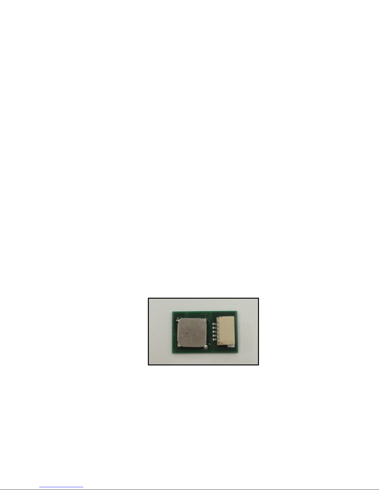
Fig. 1. Appearance of the Evaluation Module
Page 4
CONFIDENTIAL
4
1.2 Application Examples
Below show some application examples that use this evaluation module.
1.Anti-thief Vibration Detect ion 2.Abnormal Motor Vibration Detection 3.Input Devices
Fig. 2. Application Examples
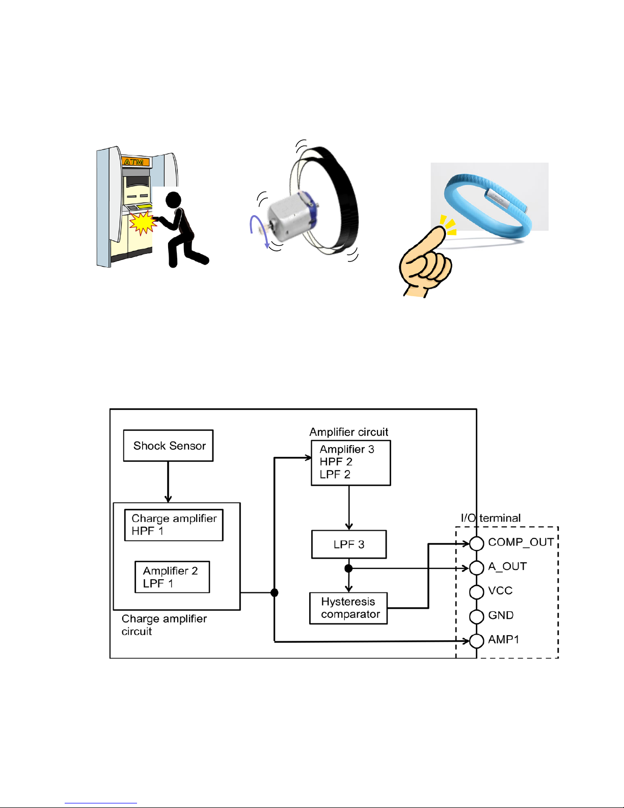
1.3 Functional Block Diagram
Fig. 3 shows the functional block diagram of the evaluation module.
Fig. 3. Functional Block Diagram
Note 1: Refer to chapter 3.1 det ai ls about「I/O Terminal」
Page 5
CONFIDENTIAL
5
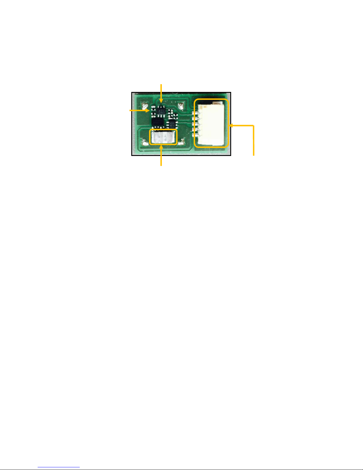
1.4 Functional Block Layout Diagram
Fig. 4. shows a functional block layout of the ev aluation module.
Fig. 4. Functional Block Layout Diagram
Comparator Circuit
Charge Amplifier
Circuit
Shock Sensor
Connector
(I/O terminal)
Page 6
CONFIDENTIAL
6
2 Evaluation Procedures
The following shows an examp le of the evaluation procedures for usi ng this evaluation module.
① Attach this module to the target of measurement.
(Usually at our company, w e use the Double-side tape shown b el ow . Note 2.)
<Reference>
Fig 5. Double-side Tape of Nich iban Co., Ltd
Note 2: Please put the Double-side tape in whole surface of back side evaluation module and put
uniformly-flat, in order that the acceleration which you want to get can transact to t he evaluation module.
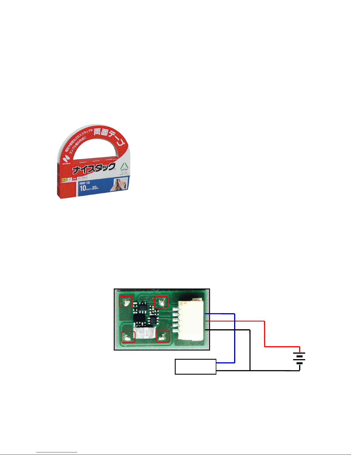
② Supply predefined voltage (e.g.3.3V) to the board t hrough VCC and GND at I/O Terminal.
③ When observing the waveform of the analog sig nal output, connect oscilloscope to AOUT .
When checking comparator circuit signal output, co nnec t t o COUT..
Fig. 6
. Connection Diagram of Evaluat i on M odule
④ If necessary, attach the includ ed shield cover. (Solder to the red frame of Diagram 6)
COMP_OUT
A_OUT
VCC
GND
AMP1
Oscilloscope
Page 7
CONFIDENTIAL
7
3 Specifications & Board Information
The following show the electrical specifications and the boar d i nformation of the evaluation mo dul e
when shipped..
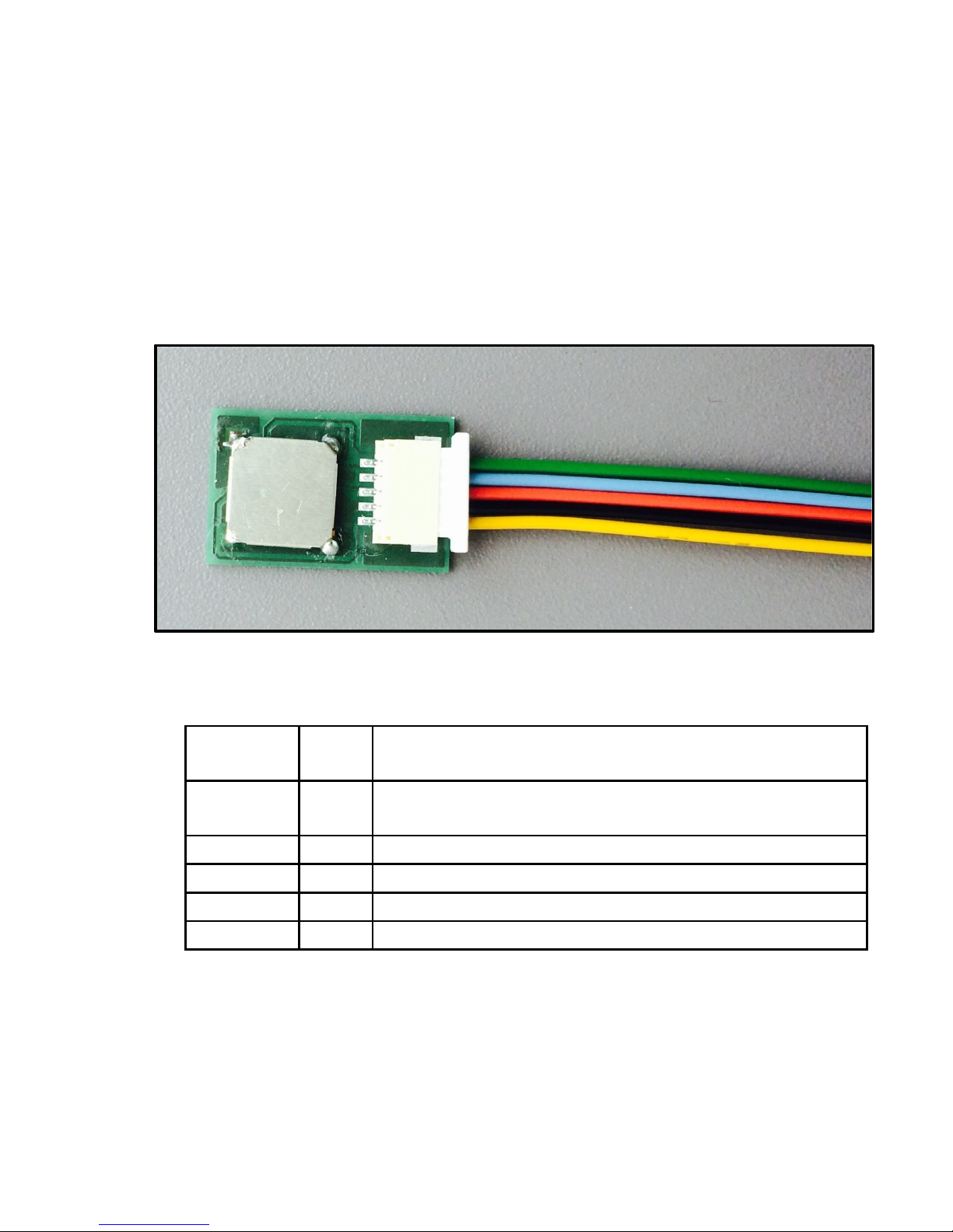
3.1 Input & Output Terminals
Fig. 7 shows detailed information of input-output terminals (I/O Terminal) on the evaluation
module.
Fig. 7. Appearance of Input-Output Terminals
Table 1. I/O Terminal List
Symbol
Wire
Color
Description
COMP_OUT
Green Comparator Output Ter minal of Sensor (after signal ampl ification).
Output is HIGH when dete ct ed. Output is LOW when not detected.
A_OUT
Blue Analog Output Terminal of Sensor (after si gnal amplification).
VCC
Red The Power Supplying Ter m ina l of Evaluation Module.
GND
Black The Grou nd Terminal of Evaluation Mod ule.
AMP1
Yellow Analog Output Terminal of Sensor (after first stage amplification).
Page 8
CONFIDENTIAL
8
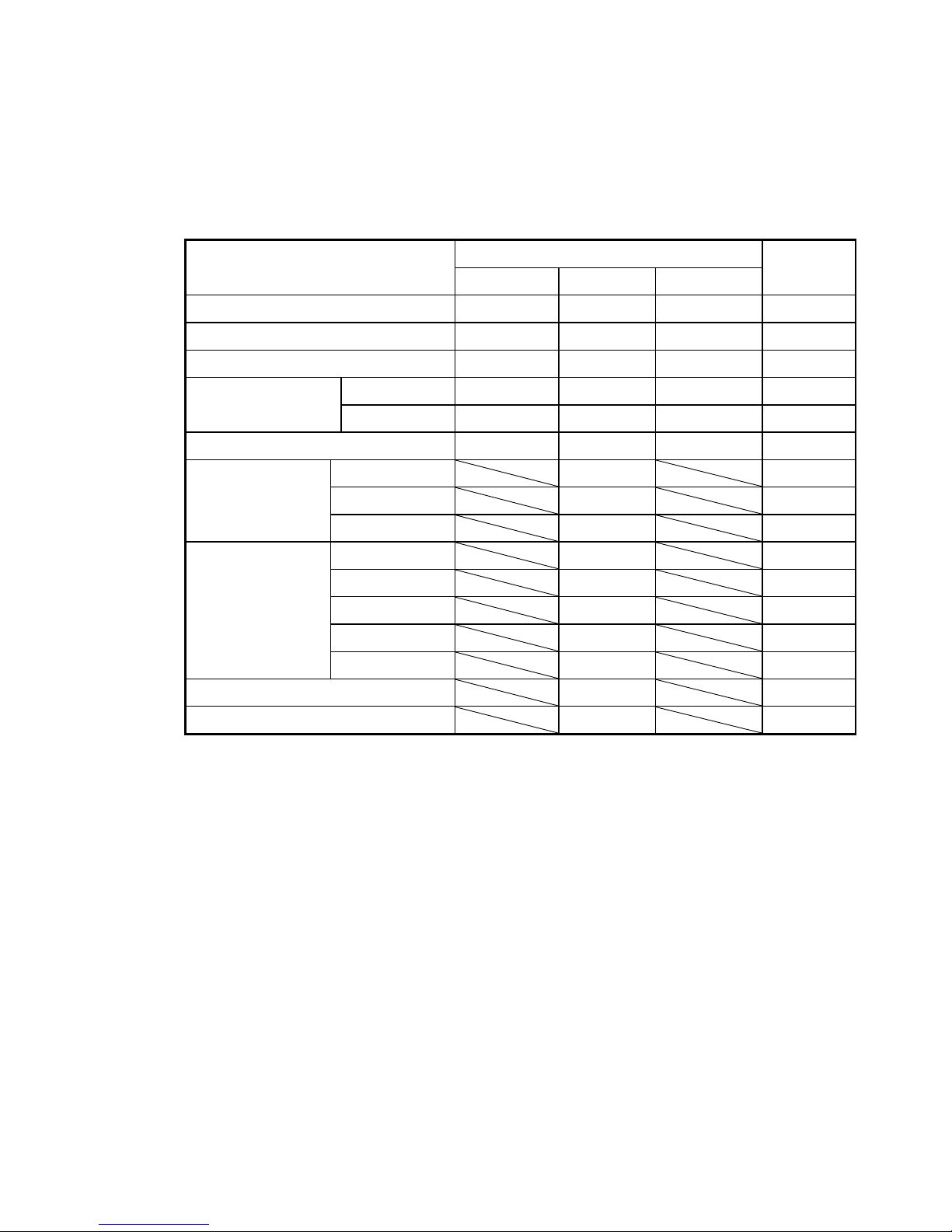
3.2 Electrical Specifications & Mechanical Specifications
The following shows the electr ic al and mechanical specifications of this evaluation mod ul e.
Table 2. Elect ric al Specifi cat ions
※Unless otherwise specified, temperature of measurement is 25ºC and supply voltage is 3.3V
Parameters
Value
Unit
Min. Typ. Max.
Operating Temperature Range
-40 - 85 ℃
VCC Input Voltage Range
2.5 - 5.0 V
A_OUT Output Voltage Range
0.0 - VCC V
COMP_OUT Output
Voltage Range
When detected
- - VCC V
When not detected
0.0 - - V
Reference Voltage
T.B.D 1.65 T.B.D V
Gain
Charge AMP
13.9 dB
AMP 2
9.6 dB
AMP 3
35.0 dB
Cutoff
frequency(-3dB)
HPF 1
106 Hz
HPF 2
106 Hz
LPF 1
2340 Hz
LPF 2
2340 Hz
LPF 3
1061 Hz
Comparator Threshold Value
2.24 V
Current Consumption (Note 3)
1.55 mA
Note 3: Current Consumption is depending on Current Con sumption of OP-AMP and Current
Consumption generated o f R ef er ence Voltage portion.
Page 9
CONFIDENTIAL
9
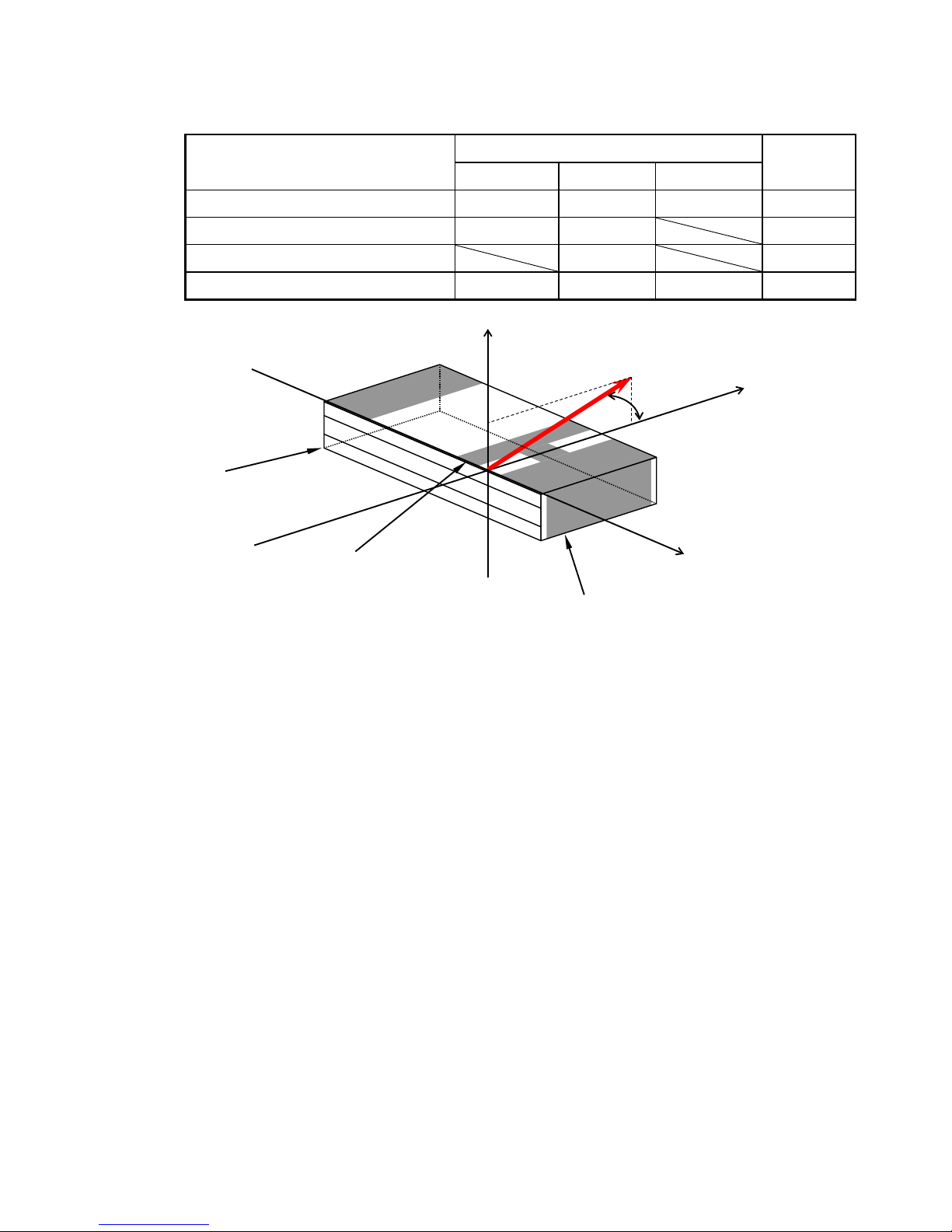
Table3. Mechanical Specifications
※Unless otherwise specified, temperature of measurement is 25ºC and supply voltage is 3.3V
Parameters
Value
Unit
Min. Typ. Max.
Circuit Sensiti v ity
T.B.D 0.35 T.B.D V/G
Sensor Resonance Frequency
21 27 kHz
Number of Axis
1
Inclination Angle of Sensor Shaft
24 25 26
°
Fig 8. Inclination of Shock Sensor Shaft (PKGS-25SXAP1-R)
Axis D : This axis (Inclination) is an acceleration applied direction, when electric charge sensitivity is
checked. It tolerance is
within ±1º.
Electrode B
Electrode A
Polarity marking
Z Y X
25±1°
D
Page 10
CONFIDENTIAL
10
Vcc
3.3
AC {G} 0
Rser=0
V1
IC2-1
C1
150p
R1
10MEG
R3
1MEG
R2
330K
C3
68p
C4
100n
R4
15K
IC2-2 R6
10k
IC1
R7
100k
R8
100k
C6
100n
15000p
C2
R9
390k
R10
820K
C7
100n
IC3
C5
82p
R5
820k
Vcc
Input
Vcc
IC2-1_OUT
Sensor_Output
Vcc
Analog_Output
Vcc
Vcc
Comparator_Output
Vref
Vcc
.ac oct 100 1 50k
.params G=1
OP A 2376AIYZ D T 1/2
Vos = 25u Vmax.
Ib = 10pA max.
GBW = 5.5MHz
Low Noise 7. 5nV
IQ = 950uA * 2
R a il t o R a il
Vref=2.24V
OPA2376AIYZDT
2/2
BU7275HFV
IDD = 1.2uA max.
Full Swing
Gain = 56
LPF 2, Fc = 2.3KHz
LPF 3,
Fc = 1.06K H z
HP F , Fc = 106Hz
U1
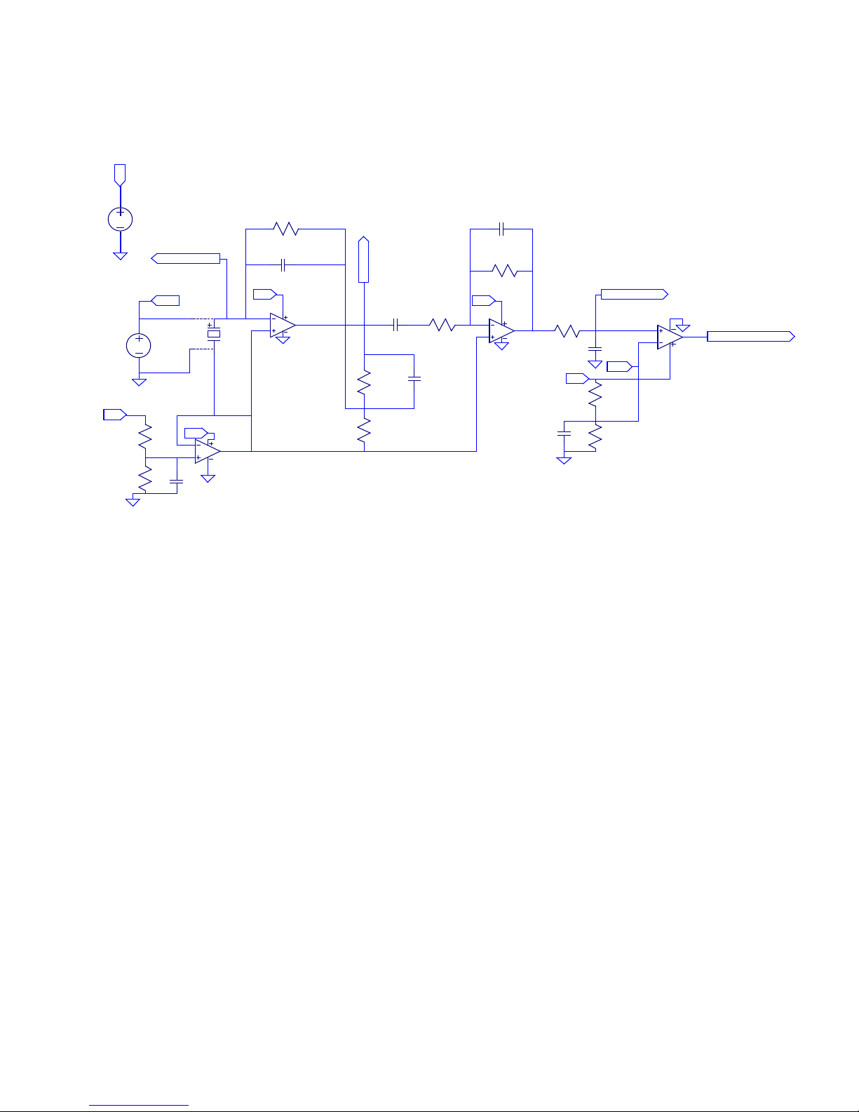
3.3 Circuit Diagram
Following shows the circuit diagram of evaluation module.
Fig 9. Circuit Diagram
(Formulas Descriptions)
Charge AMP = 20log
10
(Cf/C1) [dB] (In case of PKGS-25SXA、Cf=740pF)
AMP2 = 20log
10
(R3/R2) [dB]
AMP3 = 20log
10
(R5/R4) [dB]
HPF1 = 1/(2×π×C1 ×R1) [Hz]
HPF2 = 1/(2×π×C4 ×R4) [Hz]
LPF1 = 1/(2×π×C3 ×R3) [Hz]
LPF2 = 1/(2×π×C5 ×R5) [Hz]
LPF3 = 1/(2×π×C2 ×R6) [Hz]
Page 11
CONFIDENTIAL
11
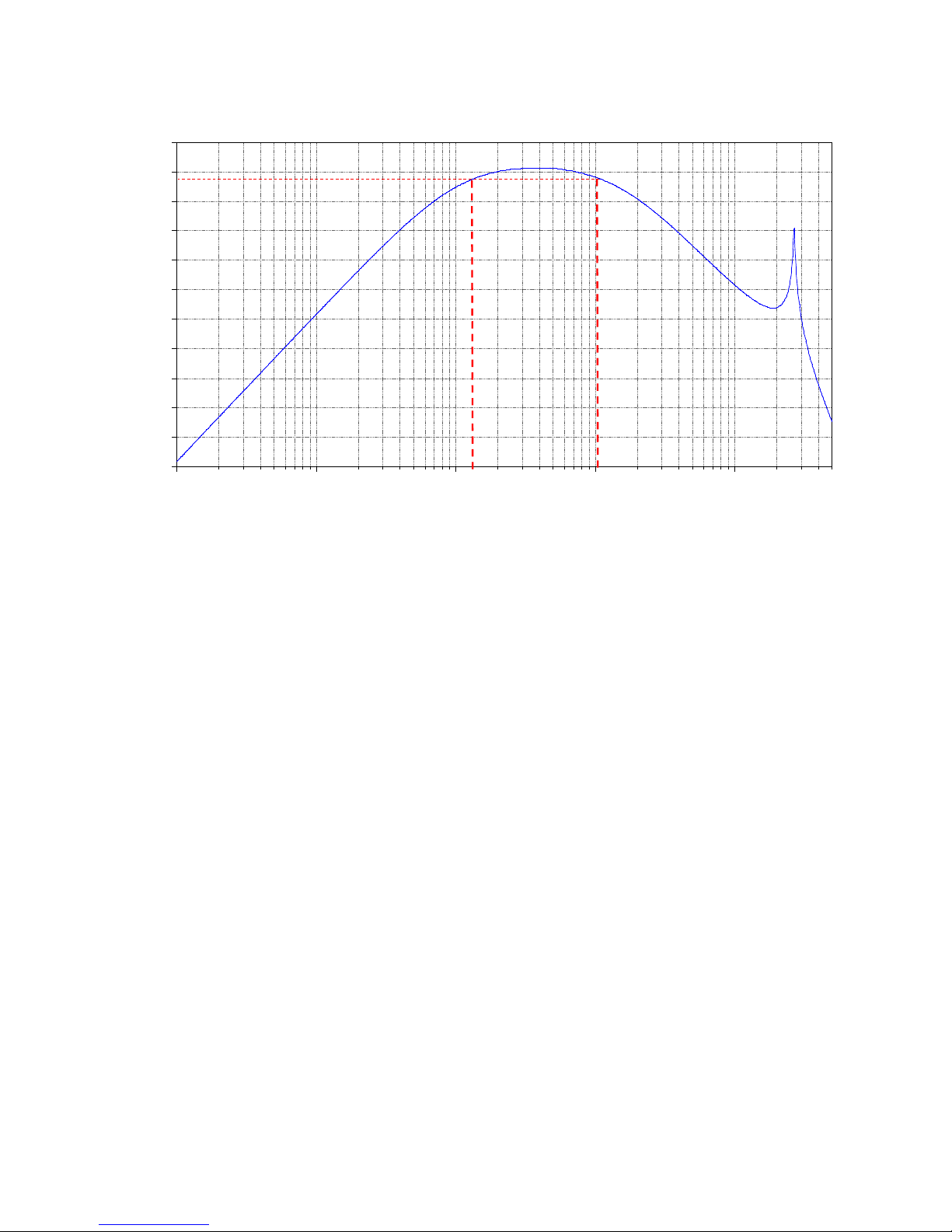
Below is the simulated frequency response curve of above circuitry (Fig.9).
Fig 10. Frequency Response Curve of PKGX-14-4010
Note 4: This Frequency Response Curve serves as referencing purpos e only. In this simulation, the
frequency response range s from 133 Hz to 1,080 KHz (-3dB po ints) . Actual frequency respon se c urve
varies according to the act ual characteristics of circuitry and components.
1Hz
10Hz
100Hz
1KHz
10KHz
-88dB
-80dB
-72dB
-64dB
-56dB
-48dB
-40dB
-32dB
-24dB
-16dB
-8dB
0dB
V(analog_output)
Page 12

CONFIDENTIAL
12
3.4 Bill of Material
The following show the bill of materials of the evaluation module when shipped.
Ref. Mfg. Part No. Description
C1 Murata GRM0332C1H151JA01 capacitor, 150pF
C2 Murata GRM033C80J153KE01 capacitor, 15nF
C3 Murata GRM0332C1H680JA01 capacitor, 68pF
C4 Murata GRM033C80G104KE19 capacitor, 100nF
C5 Murata GRM0332C1H820JA01 capacitor, 82pF
C6 Murata GRM033C80G104KE19 capacitor, 100nF
C7 Murata GRM033C80G104KE19 capacitor, 100nF
CN1 JST SM05B-SRSS-TB(LF) (SN) Connector
IC1 General BU7205HFV-TR Op-Amplifier
IC2 General OPA2376AIYZDT Op-Amplifier
IC3 General BU7275HFV-TR Op-Amplifier
R1 KOA RK73B1HTTCM106J resistor, 10M
R2 KOA RK73B1HTTCM334J resistor, 330K
R3 KOA RK73B1HTTCM105J resistor, 1M
R4 KOA RK73B1HTTCM153J resistor, 15K
R5 KOA RK73B1HTTCM824J resistor, 820K
R6 KOA RK73B1HTTCM103J resistor, 10K
R7 KOA RK73B1HTTCM104J resistor, 100K
R8 KOA RK73B1HTTCM104J resistor, 100K
R9 KOA RK73B1HTTCM394J resistor, 390K
R10 KOA RK73B1HTTCM824J resistor, 820K
U1 Murata PKGS-25SXAP1-R Shock Sensor
Table 4. Bill of Material
Page 13
CONFIDENTIAL
13
3.5 External Dimensions
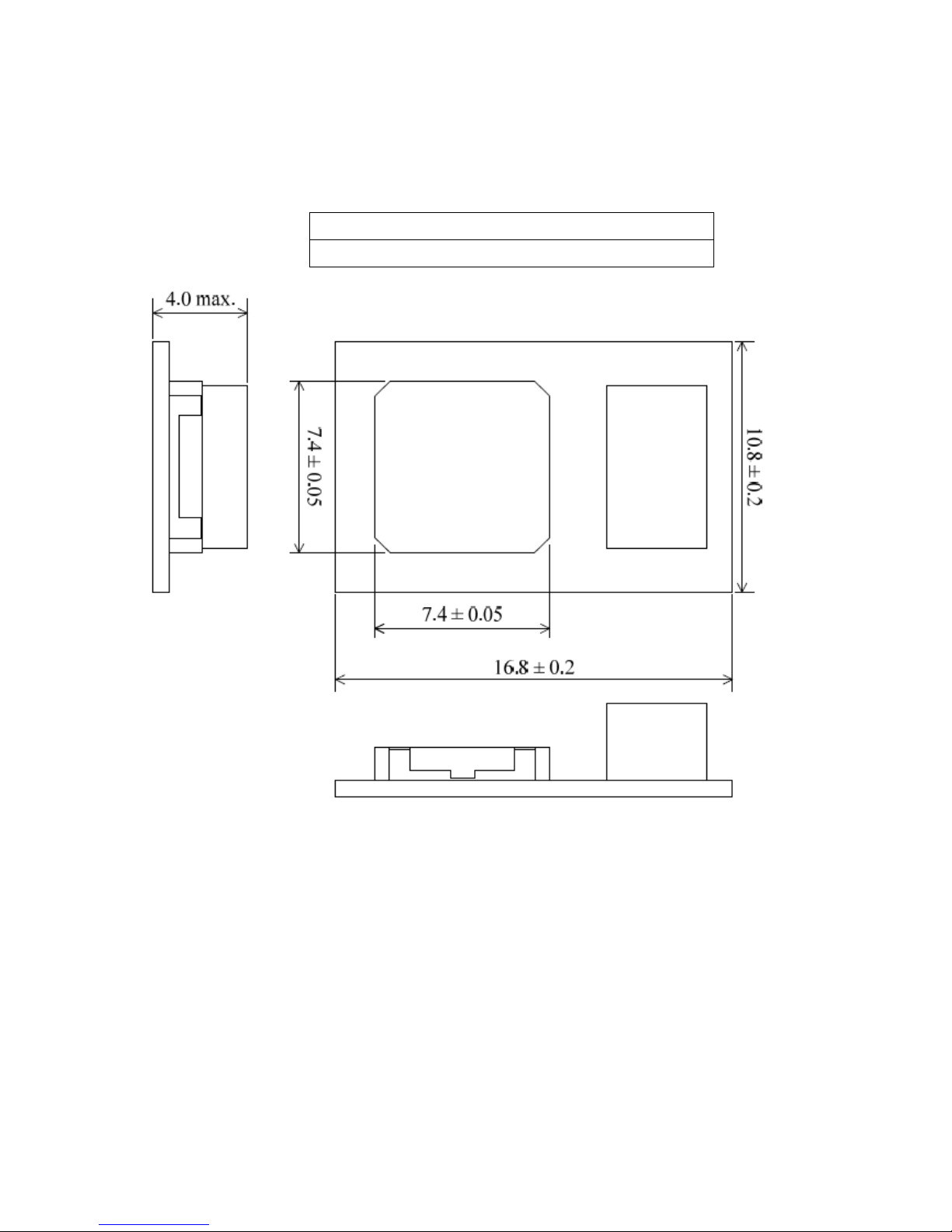
The outline dimensions of t he evaluation module are shown in the drawing below.
Table 5. External Dimensions
External Dimensions(Length × Width × Height)[mm]
16.8×10.8×4.0
Fig11. External Dimension Drawing
Note 4. The height of Connector’s portion is 3.55mm.
Connector
Page 14
CONFIDENTIAL
14
3.6 Board Layout
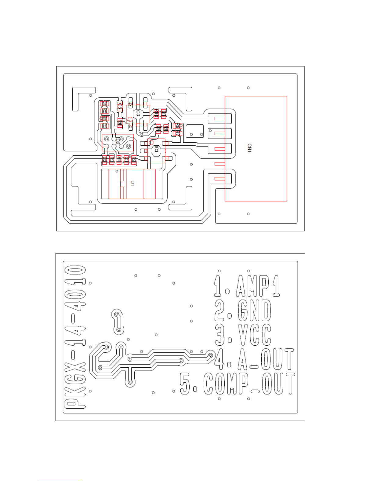
The following shows the board layout of this evaluation module.
Fig 11. Board Layout (Top Copper Layer)
Fig 12. Board Layout (Bottom Copper Layer)
Page 15

CONFIDENTIAL
15
4.Precautions
4.1 Precautions when in use
-This evaluation module cannot detect gravitational acceleration and free fal l.
-Please take off direct sunlig ht and moisture during storage of this evaluation module. There is a
possibility of corrosion on t he connector.
-Due to change of atmospheric pressure, the character ist ics of this evaluation module may change.
Please do not use in conditions where atmospheric pressure is vastly different from ground level (e.g.
vacuum and water etc).
-Please do not store the ev aluat io n module in environments which is exposed to dust, oil, corr osive
gases, acid and alkaline.
-When exposed to sudden chan ging temperature, thi s evaluation module may extemporarily generate
output even when there is no applying acceleration. The output is affected by different conditions of
stress and individual differ ences of sensor. Please evaluate deeply influence of t emperature change
which you expect by your set.
-Depending on the environm ent of usage, is evaluation module may be susceptible t o external
electrical noise. In this cas e, please use the shield cover provided for noise reduction.
-Mounting of provided shield cover on this evaluation module will be performed by user s as needed.
Please be extreme caution not t o caus e short circuit during the installation of shielding.
-This evaluation module detects acceleration that is transmitted through your h ousing and your
mounting board. Please use this module after consi dering characteristics of mechanical acceleration
transmission in your set d eeply.
-Depending on the mounting conditions of the evaluation module internal resonance of set and
interferences from inherit ed frequencies of each co mp onent, there is a possibility that ac celeration is
not transmitted from this produc t as intended by user.
4.2 Other Precautions
This document and evaluat ion module shall not;
・ -be used for other purpose than the purpose for evaluation of Murata’s sensor pr oduc t s,
・ -be disclosed, transferred and/or lent t o t hird par t y,
・ -be copied, reproduced and published.
・ WE HEREBY DISCLAIM FROM ANY AND ALL WARRANTIES FOR THIS DOCUMENT
THIS EVALUATION BOARD, EITHER EXPRESS OR IMPLIED, INCLUDING WITHOUT
MITATION ANY WARRANTY OF DESIGN, MERCHANTABLITY, FITNESS FOR A
RTICULAR PURPOSE, OR AGAINST INFRINGEMENT OF INTELLECTUAL PROPERTY
RIGHTS
Page 16

CONFIDENTIAL
16
・ We SHALL NOT BE LIABLE FOR ANY DAMAGES OR LOSSES, INCLUDING CLAIMS ON A THIRD
PARTY, ARISING OUT OF OR RELATING TO THE USE OF THIS DOCUMENT AN D EVAL UA TION
BOARD
・ It is the user’ s responsibility for any changes to circuit. Any change rel at ed activities to the circuit will
result a void in warranty.
 Loading...