

Page 1
N1-2657: TypeZF Mother Board Quick-Start Guide
1 / 4
TypeZF Mother Board Quick Start Guide
This Quick-Start Guide provides instructions for basic procedure to use TypeZF Mother Board.
1. Contents List
Check that the following components are included.
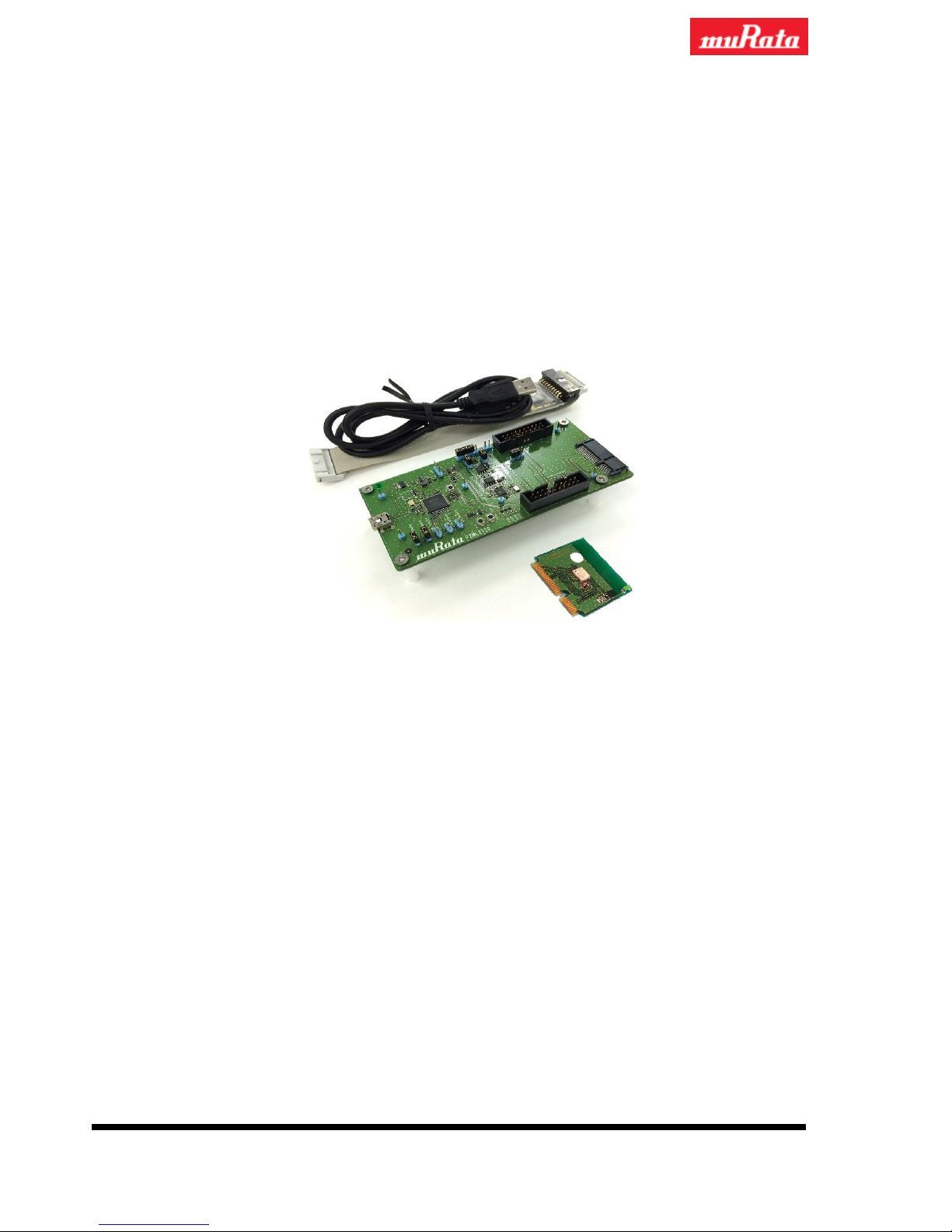
Mother Board 1 pc
J-Link Lite ARM with cable 1 pc
TypeZF Daughter Board 1pc
Figure 1 Contents overview
Need to prepare by yourself.
Please prepare USB-mini B Cable to connect the Mother Board to PC.
2. Schematics and layout reference
Mother Board
Schematics: SDKMother_v2.1_schema_131228.pdf
Layout: SDKMother_v2.1_layout_131228.pdf
TypeZF Daughter Board
Schematics: ZF-SDKDaughter_schema_131228.pdf
Layout: ZF-SDKDaughter_layout_140106pdf
TypeZF Daughter Board
J-Link Lite ARM with cable
Mother Board
Page 2
N1-2657: TypeZF Mother Board Quick-Start Guide
2 / 4
3. Hardware description
3.1. Hardware description
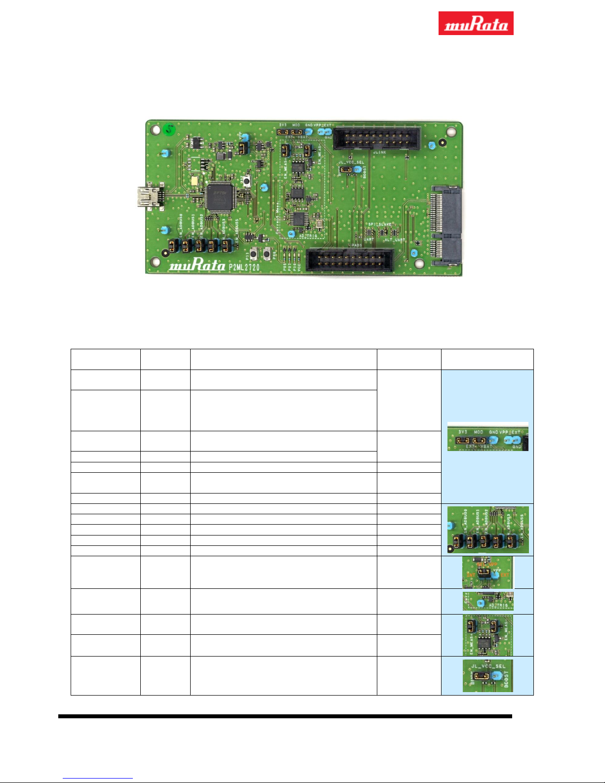
Figure 2 Overview of the Mother Board
Table 1 Jumpers of the Mother Board
Name
Function
Description
Default
Settings
Photo
3V3
Output
Regulated 3.0V output generated internally
by Mother Board.
Tied
EXT
Input
Input for the
Current Measurement
circuit
block.
(should be connected to 3V3 pin directly or
external power supply)
MOD
Output
Output from the
Current Measurement
circuit block.
Tied
VBAT
Input
Power input for Daughter Board
GND
Ground
Ground
VPP_EXT
Input
Power input for External VPP (only used
when VPP is supplied externally.)
Open
GND
Ground
Ground
EN_ADBUS0
Jumper
Should be tied to enable RXD/CK
Tied
EN_ADBUS1
Jumper
Should be tied to enable TXD/DI
Tied
EN_ADBUS2
Jumper
Should be tied to enable CTS/WAKE/DO
Tied
EN_ADBUS3
Jumper
Should be tied to enable RTS/RDY/CS
Tied
EN_ADBUS5
Jumper
Should be tied to enable DTR/INT
Tied
SEL_VPP
Jumper
Select VPP source, internal or external
(VPP_EXT)
Select “INT”
AD_TRIG
Input
TBD. Can be left open if not used.
Open
EN_MEAS+
Jumper
Should be tied to enable input of the
Current
Measurement
circuit block.
Tied
EN_MEAS-
Jumper
Should be tied to enable output of the
Current Measurement
circuit block.
Tied
JL_VCC_SEL
Jumper
Select J-Link VCC source. Should be tied
center pin and either of “BUCK” / ”BOOST”
depends on the Daughter Board schematics.
Select
“BUCK”
Page 3
N1-2657: TypeZF Mother Board Quick-Start Guide
3 / 4
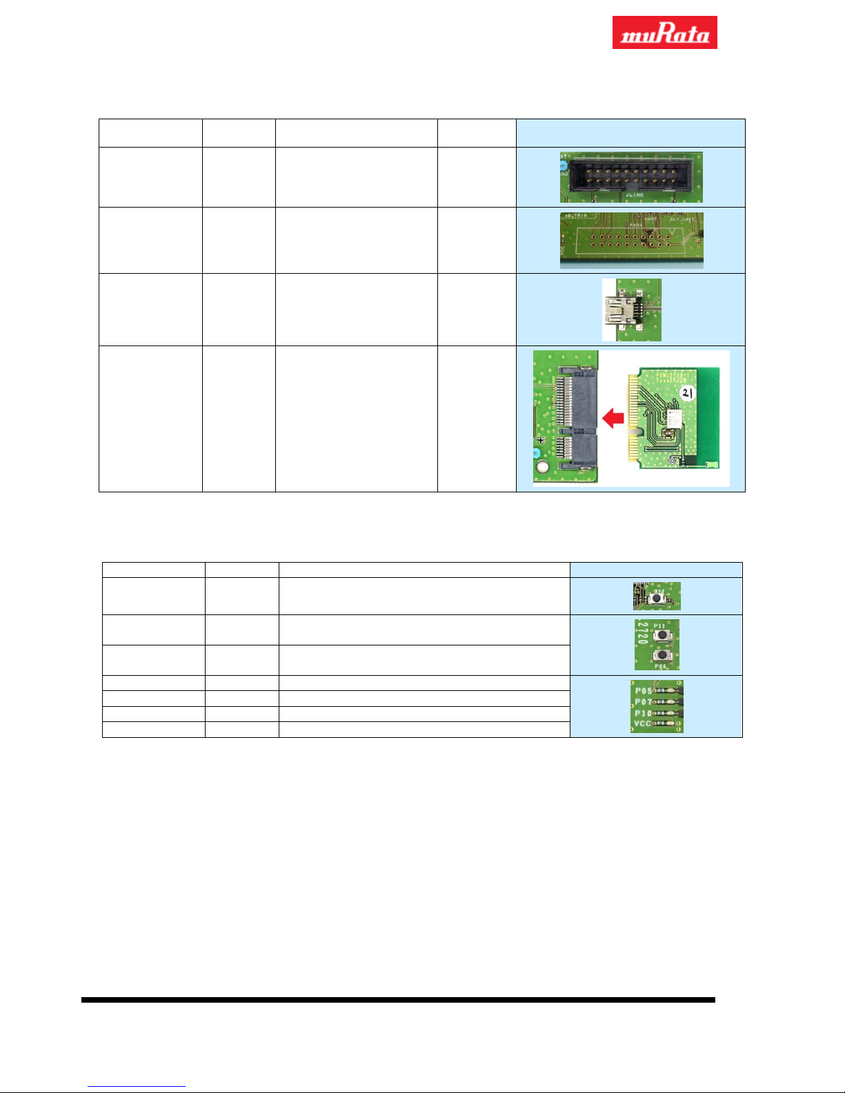
Table 2 Connectors and Pin headers of the Mother board
Name
Function
Description
Default
Settings
Photo
JLINK
I/O
JLINK connector
PADS
I/O
Debug pins
USB
I/O
USB connector
Daughter
I/O
Connect to the Daughter
Board
Table 3 Buttons and LEDs of the Mother board
Name
Function
Description
Photo
RST
Input
Connected to RST of the Daughter Board
P11
Input
Connected to P1_1 of the Daughter Board
P06 Input
Connected to P0_5 of the Daughter Board
(*1)
P05
LED
Connected to P0_5 of the Daughter Board
P07
LED
Connected to P0_7 of the Daughter Board
P10
LED
Connected to P1_0 of the Daughter Board
VCC
LED
Connected to VCC_EXT of the Mother Board
Note:
(*1)
will be fixed to be connected to P0_6 in the next release
Page 4
N1-2657: TypeZF Mother Board Quick-Start Guide
4 / 4
3.2. Configurations of the Mother board
Table 4 Mother Board configuration
#
Description
Related Pins
To do
1
UART connection
EN_ADBUS0
EN_ADBUS1
Both pins are tied by jumpers.
2
Select internal/external
Power Supply
3V3
EXT
When using internal 3.0V supply:
- 3V3-EXT and MOD-VBAT are tied by jumpers.
When using external power supply:
- 3V3-EXT is open.
- External power is supplied to EXT pin.
- MOD-VBAT is still tied.
3
Current Measurement
(Internally)
EN_MEAS+
EN_MEAS-
Both pins are tied by jumper.
4
OTP write
SEL_VPP
VPP_EXT
When using internal VPP source:
- SEL_VPP is set to “INT”
When using external VPP source:
- SEL_VPP is set to “EXT”
- External 6.8V is supplied to VPP_EXT pin
4. Quick Start
This chapter shows how to quickly set up the environment of Mother Board.
1. Connect the Daughter Board to the Mother Board.
2. Connect J-Link adapter to the Mother Board. (Only if J-Link debugging is used)
3. Connect the Mother Board and PC by USB cable.
About Software and other things, please refer following document by Dialog.
“DA14580_SDK_v_2.0.4_ES4_User_Guide.pdf”
 Loading...