

Page 1
• This PDF catalog is downloaded from the website of Murata Manufacturing co., ltd. Therefore, it’s specifications are subject to change or our products in it may be discontinued without advance notice. Please check with our
!Note
• Please read rating and !CAUTION (for storage, operating, rating, soldering, mounting and handling) in this catalog to prevent smoking and/or burning, etc.
!Note
sales representatives or product engineers before ordering.
• This catalog has only typical specifications because there is no space for detailed specifications. Therefore, please approve our product specifications or transact the approval sheet for product specifications before ordering.
• This PDF catalog has only typical specifications because there is no space for detailed specifications. Therefore, please approve our product specifications or transact the approval sheet for product specifications before ordering.
Chip Monolithic Ceramic Capacitors
Low ESL LLL/LLA/LLM Series
C02E.pdf
05.12.14
12
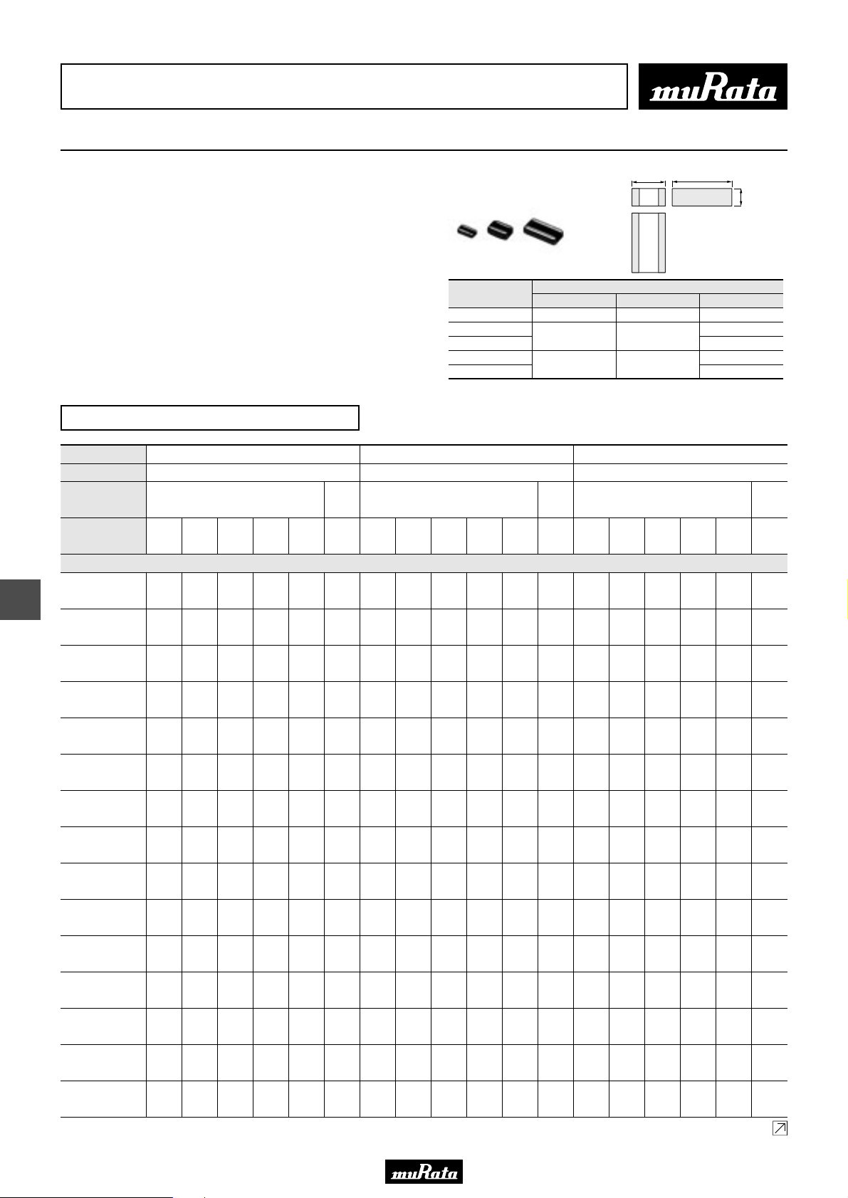
■ Features (Reversed geometry Low ESL Type)
1. Low ESL, good for noise reduction for high
frequency
2. Small, high cap
■ Applications
1. High speed micro processor
2. High frequency digital equipment
Part Number
LLL185
LLL216
LLL219
LLL317
LLL31M
L
1.6 ±0.1
2.0 ±0.1
3.2 ±0.15
Reversed geometry Low ESL Type
Part Number
L x W
TC
Rated Volt.
Capacitance (Capacitance part numbering code) and T (mm) Dimension (T Dimension part numbering code)
2200pF
3300pF
4700pF
6800pF
10000pF
15000pF
22000pF
33000pF
47000pF
68000pF
0.10µF
0.15µF
0.22µF
0.33µF
0.47µF
50
(1H)25(1E)16(1C)10(1A)
0.5
(222)
(5)
0.5
(332)
(5)
0.5
(472)
(5)
(682)
(103)
(153)
(223)
(333)
(473)
(683)
(104)
(154)
(224)
(334)
(474)
0.5
(5)
0.5
(5)
0.5
(5)
0.5
(5)
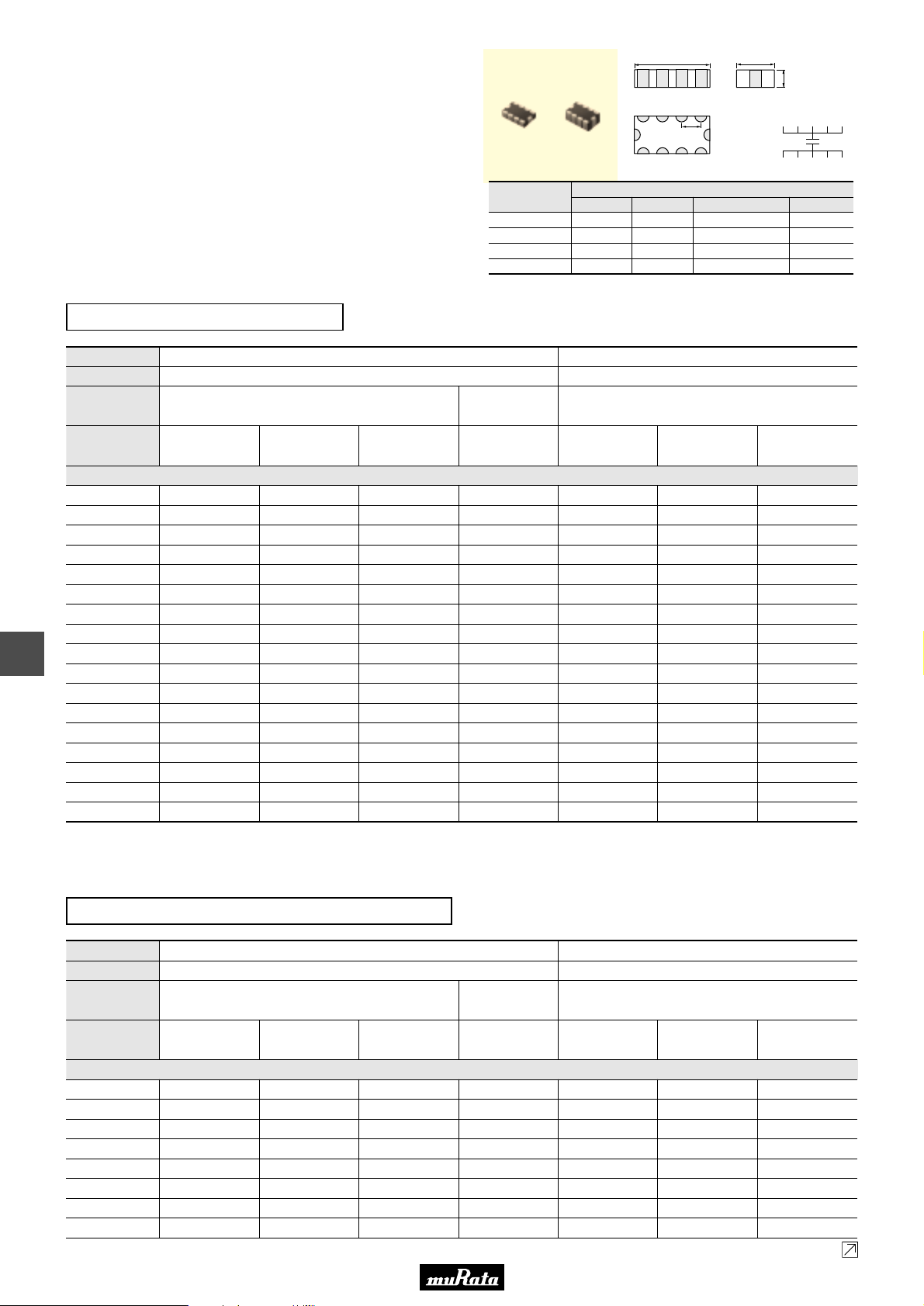
LLL18
1.6x0.8
X7R
(R7)
0.5
(5)
0.5
(5)
0.5
(5)
0.5
(5)
0.5
(5)
0.5
(5)
0.5
(5)
X7S
(C7)
6.3
4
(0J)
(0G)50(1H)25(1E)16(1C)10(1A)
0.6
(6)
0.6
(6)
0.6
(6)
0.6
(6)
0.6
0.6
(6)
(6)
0.85
0.6
(9)
(6)
0.6
(6)
0.6
(6)
0.6
(6)
0.5
(5)
0.5
(5)
0.5
(5)
0.5
(5)
0.85
(9)
LLL21
2.0x1.25
X7R
(R7)
0.6
(6)
0.6
(6)
0.6
(6)
0.6
(6)
0.6
(6)
0.6
(6)
0.6
(6)
0.85
(9)
X7S
(C7)
6.3
4
(0J)
(0G)50(1H)25(1E)16(1C)10(1A)
Dimensions (mm)
0.7
(7)
0.7
0.7
(7)
(7)
0.7
0.7
(7)
(7)
0.7
0.7
(7)
(7)
0.7
0.7
(7)
(7)
0.7
0.7
(7)
(7)
1.15
0.7
(M)
(7)
1.15
0.7
(M)
(7)
1.15
(M)
1.15
(M)
1.15
(M)
W
W
0.8 ±0.1
1.25 ±0.1
1.6 ±0.15
L
T
T
0.6 max.
0.6 ±0.1
0.85 ±0.1
0.7 ±0.1
1.15 ±0.1
LLL31
3.2x1.6
X7R
(R7)
6.3
(0J)
0.7
(7)
0.7
(7)
Continued on the following page.
X5R
(R6)
6.3
(0J)
64
Page 2
• This PDF catalog is downloaded from the website of Murata Manufacturing co., ltd. Therefore, it’s specifications are subject to change or our products in it may be discontinued without advance notice. Please check with our
!Note
• Please read rating and !CAUTION (for storage, operating, rating, soldering, mounting and handling) in this catalog to prevent smoking and/or burning, etc.
!Note
sales representatives or product engineers before ordering.
• This catalog has only typical specifications because there is no space for detailed specifications. Therefore, please approve our product specifications or transact the approval sheet for product specifications before ordering.
• This PDF catalog has only typical specifications because there is no space for detailed specifications. Therefore, please approve our product specifications or transact the approval sheet for product specifications before ordering.
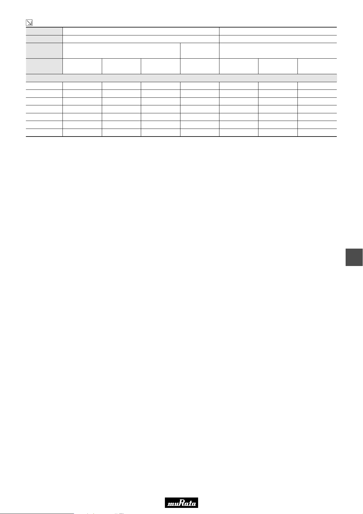
Continued from the preceding page.
Part Number
L x W
TC
LLL18
1.6x0.8
X7R
(R7)
X7S
(C7)
LLL21
2.0x1.25
X7R
(R7)
X7S
(C7)
LLL31
3.2x1.6
X7R
(R7)
C02E.pdf
05.12.14
X5R
(R6)
Rated Volt.
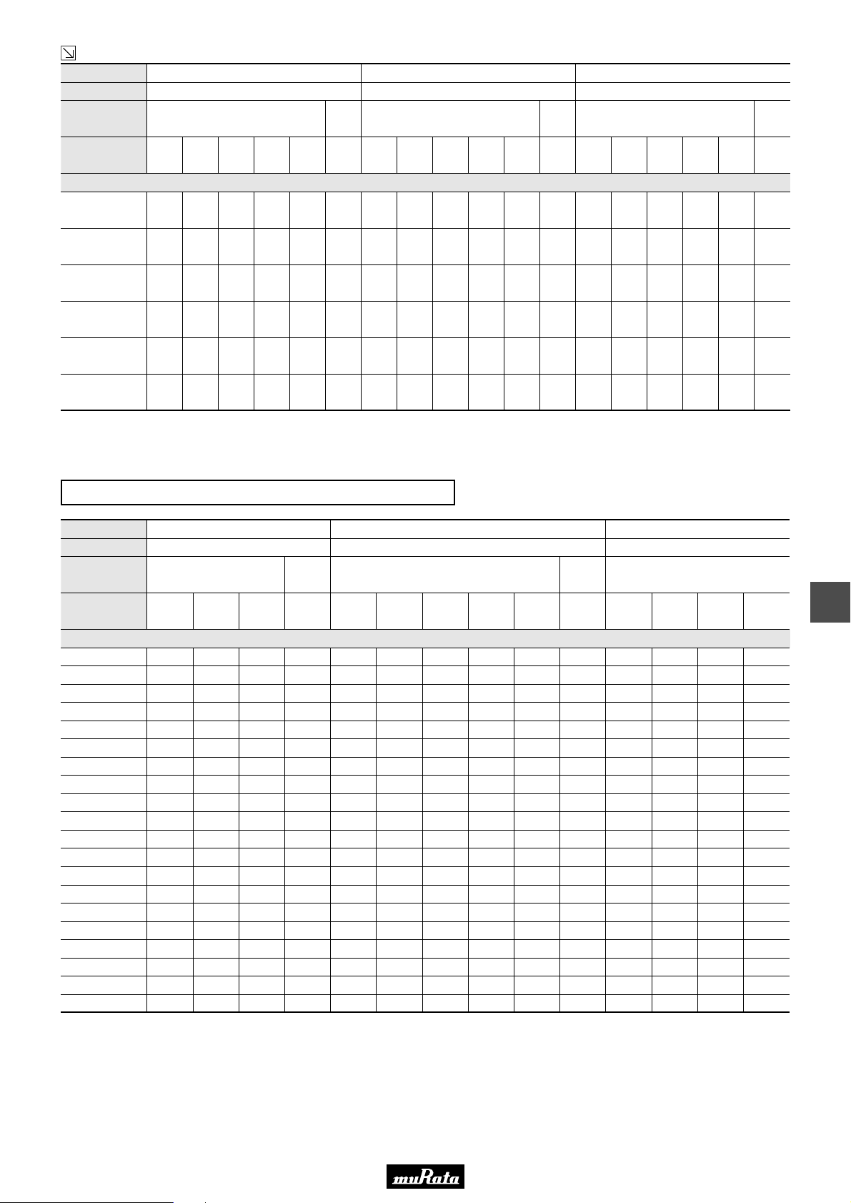
Capacitance (Capacitance part numbering code) and T (mm) Dimension (T Dimension part numbering code)
0.68µF
1.0µF
1.5µF
2.2µF
4.7µF
The part numbering code is shown in ( ).
Dimensions are shown in mm and Rated Voltage in Vdc.
50
(1H)25(1E)16(1C)10(1A)
(684)
(105)
(155)
(225)
(475)
10µF
(106)
6.3
4
(0J)
(0G)50(1H)25(1E)16(1C)10(1A)
0.5
(5)
6.3
4
(0J)
(0G)50(1H)25(1E)16(1C)10(1A)
0.85
(9)
0.85
(9)
0.85
(9)
0.85
(9)
Reversed geometry Low ESL Type Low Profile
Part Number
L x W
TC
X7R
(R7)
LLL18
1.6x0.8
X7S
(C7)
LLL21
2.0x1.25
X7R
(R7)
X7S
(C7)
1.15
(M)
1.15
(M)
0.7
(7)
0.7
(7)
1.15
(M)
1.15
(M)
LLL31
3.2x1.6
X7R
(R7)
6.3
(0J)
0.7
(7)
0.7
(7)
1.15
(M)
6.3
(0J)
1.25
(B)
Rated Volt.
Capacitance (Capacitance part numbering code) and T (mm) Dimension (T Dimension part numbering code)
680pF(681) 0.5(5)
1000pF(102) 0.5(5)
1500pF(152) 0.5(5)
2200pF(222) 0.5(5)
3300pF(332) 0.5(5)
4700pF(472) 0.5(5)
6800pF(682) 0.5(5)
10000pF(103) 0.5(5) 0.5(5) 0.5(5) 0.5(5) 0.5(5)
15000pF(153) 0.5(5) 0.5(5) 0.5(5) 0.5(5) 0.5(5) 0.5(5)
22000pF(223) 0.5(5) 0.5(5) 0.5(5) 0.5(5) 0.5(5)
33000pF(333) 0.5(5) 0.5(5) 0.5(5) 0.5(5) 0.5(5)
47000pF(473) 0.5(5) 0.5(5) 0.5(5) 0.5(5)
68000pF(683) 0.5(5) 0.5(5) 0.5(5) 0.5(5)
0.10µF(104) 0.5(5) 0.5(5) 0.5(5) 0.5(5)
0.15µF(154) 0.5(5) 0.5(5)
0.22µF(224) 0.5(5) 0.5(5) 0.5(5)
0.33µF(334) 0.5(5) 0.5(5) 0.5(5)
0.47µF(474) 0.5(5) 0.5(5)
0.68µF(684) 0.5(5)
1.0µF(105) 0.5(5)
The part numbering code is shown in ( ).
Dimensions are shown in mm and Rated Voltage in Vdc.
25
(1E)16(1C)
10
(1A)
4
(0G)50(1H)25(1E)16(1C)10(1A)
6.3
(0J)
4
(0G)50(1H)25(1E)16(1C)
10
(1A)
12
65
Page 3
• This PDF catalog is downloaded from the website of Murata Manufacturing co., ltd. Therefore, it’s specifications are subject to change or our products in it may be discontinued without advance notice. Please check with our
!Note
• Please read rating and !CAUTION (for storage, operating, rating, soldering, mounting and handling) in this catalog to prevent smoking and/or burning, etc.
!Note
sales representatives or product engineers before ordering.
• This catalog has only typical specifications because there is no space for detailed specifications. Therefore, please approve our product specifications or transact the approval sheet for product specifications before ordering.
• This PDF catalog has only typical specifications because there is no space for detailed specifications. Therefore, please approve our product specifications or transact the approval sheet for product specifications before ordering.
L
W
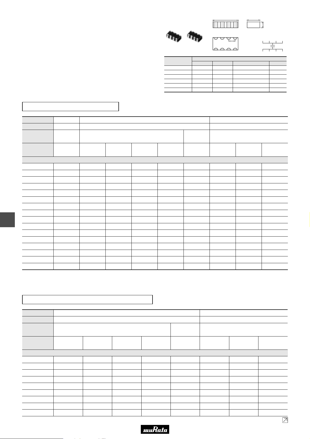
■ Features (Eight Terminals Low ESL Type)
1. Low ESL (100pH) , suitable to decoupling capacitor
for 1GHz clock speed IC.
2. Small, large cap
■ APPLICATIONS
1. High speed micro processor
2. High frequency digital equipment.
Part Number
LLA185
LLA215
LLA219
LLA315
LLA319
LLA31M
1.6 ±0.1 0.8 ±0.1 0.4 ±0.10.5 +0.05/-0.1
2.0 ±0.1 1.25 ±0.1 0.5 ±0.050.5 +0.05/-0.1
2.0 ±0.1 1.25 ±0.1 0.5 ±0.050.85 ±0.1
3.2 ±0.15 1.6 ±0.15 0.8 ±0.10.5 +0.05/-0.1
3.2 ±0.15 1.6 ±0.15 0.8 ±0.10.85 ±0.1
3.2 ±0.15 1.6 ±0.15 0.8 ±0.11.15±0.1
q w e r
P
i u y t
Dimensions (mm)
L W T
Eight Terminals Low ESL Type
C02E.pdf
05.12.14
T
Equivalent Circuit
q e t u
w r y i
P
12
Part Number
L x W
TC
Rated Volt.
Capacitance (Capacitance part numbering code) and T (mm) Dimension (T Dimension part numbering code)
10000pF(103) 0.85(9)
15000pF(153) 0.85(9)
22000pF(223) 0.85(9)
33000pF(333) 0.85(9)
47000pF(473) 0.85(9)
68000pF(683) 0.85(9)
0.10µF(104) 0.85(9) 0.85(9)
0.15µF(154) 0.85(9) 1.15(M)
0.22µF(224) 0.85(9) 0.85(9)
0.33µF(334) 0.5(5) 0.85(9) 0.85(9)
0.47µF(474) 0.5(5) 0.85(9) 0.85(9)
0.68µF(684) 0.85(9) 0.85(9)
1.0µF(105) 0.5(5) 0.85(9) 0.85(9)
1.5µF(155) 0.85(9) 0.85(9)
2.2µF(225) 0.85(9) 0.85(9)
4.7µF(475) 0.85(9)
The part numbering code is shown in ( ).
Dimensions are shown in mm and Rated Voltage in Vdc.
LLA18
1.6x0.8
X7S
(C7)
4
(0G)
25
(1E)
16
(1C)
X7R
(R7)
LLA21
2.0x1.25
10
(1A)
6.3
(0J)
X7S
(C7)
4
(0G)
16
(1C)
LLA31
3.2x1.6
X7R
(R7)
10
(1A)
4
(0G)
Eight Terminals Low ESL Type Low Profile
Part Number
L x W
TC
Rated Volt.
Capacitance (Capacitance part numbering code) and T (mm) Dimension (T Dimension part numbering code)
10000pF(103) 0.5(5)
15000pF(153) 0.5(5)
22000pF(223) 0.5(5)
33000pF(333) 0.5(5)
47000pF(473) 0.5(5)
68000pF(683) 0.5(5)
0.10µF(104) 0.5(5) 0.5(5)
0.15µF(154) 0.5(5) 0.5(5) 0.5(5)
0.22µF(224) 0.5(5) 0.5(5) 0.5(5)
25
(1E)
16
(1C)
66
X7R
(R7)
LLA21
2.0x1.25
10
(1A)
6.3
(0J)
X7S
(C7)
4
(0G)
16
(1C)
LLA31
3.2x1.6
X7R
(R7)
10
(1A)
Continued on the following page.
6.3
(0J)
Page 4
• This PDF catalog is downloaded from the website of Murata Manufacturing co., ltd. Therefore, it’s specifications are subject to change or our products in it may be discontinued without advance notice. Please check with our
!Note
• Please read rating and !CAUTION (for storage, operating, rating, soldering, mounting and handling) in this catalog to prevent smoking and/or burning, etc.
!Note
sales representatives or product engineers before ordering.
• This catalog has only typical specifications because there is no space for detailed specifications. Therefore, please approve our product specifications or transact the approval sheet for product specifications before ordering.
• This PDF catalog has only typical specifications because there is no space for detailed specifications. Therefore, please approve our product specifications or transact the approval sheet for product specifications before ordering.
Continued from the preceding page.
Part Number
L x W
TC
X7R
(R7)
LLA21
2.0x1.25
X7S
(C7)
LLA31
3.2x1.6
X7R
(R7)
C02E.pdf
05.12.14
Rated Volt.
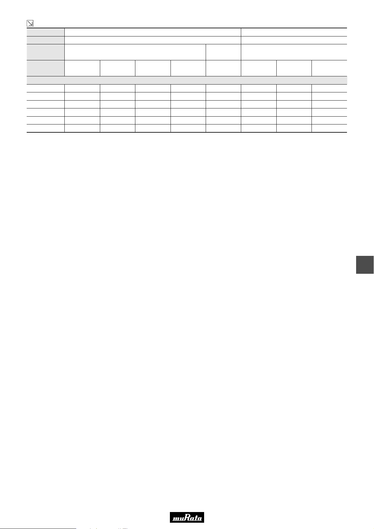
Capacitance (Capacitance part numbering code) and T (mm) Dimension (T Dimension part numbering code)
0.33µF(334) 0.5(5) 0.5(5) 0.5(5)
0.47µF(474) 0.5(5) 0.5(5)
0.68µF(684) 0.5(5) 0.5(5)
1.0µF(105) 0.5(5) 0.5(5)
1.5µF(155) 0.5(5) 0.5(5)
2.2µF(225) 0.5(5) 0.5(5)
The part numbering code is shown in ( ).
Dimensions are shown in mm and Rated Voltage in Vdc.
25
(1E)
16
(1C)
10
(1A)
6.3
(0J)
4
(0G)
16
(1C)
10
(1A)
6.3
(0J)
12
67
Page 5
• This PDF catalog is downloaded from the website of Murata Manufacturing co., ltd. Therefore, it’s specifications are subject to change or our products in it may be discontinued without advance notice. Please check with our
!Note
• Please read rating and !CAUTION (for storage, operating, rating, soldering, mounting and handling) in this catalog to prevent smoking and/or burning, etc.
!Note
sales representatives or product engineers before ordering.
• This catalog has only typical specifications because there is no space for detailed specifications. Therefore, please approve our product specifications or transact the approval sheet for product specifications before ordering.
• This PDF catalog has only typical specifications because there is no space for detailed specifications. Therefore, please approve our product specifications or transact the approval sheet for product specifications before ordering.
L
W
■ Features (Ten Terminals Low ESL Type)
1. Low ESL (45pH), suitable to decoupling capacitor
for 2GHz clock speed IC.
2. Small, large cap
■ APPLICATIONS
1. High speed micro processor
2. High frequency digital equipment
Part Number
LLM215
LLM219
LLM315
LLM31M
2.0 ±0.1 1.25 ±0.1 0.5 ±0.050.5 +0.05/-0.1
2.0 ±0.1 1.25 ±0.1 0.5 ±0.050.85 ±0.1
3.2 ±0.15 1.6 ±0.15 0.8 ±0.10.5 +0.05/-0.1
3.2 ±0.15 1.6 ±0.15 0.8 ±0.11.15±0.1
q w e r
P
t!0
o i u y
Dimensions (mm)
L W T
Ten Terminals Low ESL Type
C02E.pdf
05.12.14
T
Equivalent Circuit
q e t u
w r y io!0
P
12
Part Number
L x W
TC
Rated Volt.
Capacitance (Capacitance part numbering code) and T (mm) Dimension (T Dimension part numbering code)
10000pF(103) 0.85(9)
15000pF(153) 0.85(9)
22000pF(223) 0.85(9)
33000pF(333) 0.85(9)
47000pF(473) 0.85(9)
68000pF(683) 0.85(9)
0.10µF(104) 0.85(9) 1.15(M)
0.15µF(154) 0.85(9) 1.15(M)
0.22µF(224) 0.85(9) 1.15(M)
0.33µF(334) 0.85(9) 1.15(M)
0.47µF(474) 0.85(9) 1.15(M)
0.68µF(684) 0.85(9) 1.15(M)
1.0µF(105) 0.85(9) 1.15(M)
1.5µF(155) 0.85(9) 1.15(M)
2.2µF(225) 0.85(9) 1.15(M)
3.3µF(335) 1.15(M)
4.7µF(475) 1.15(M)
The part numbering code is shown in ( ).
Dimensions are shown in mm and Rated Voltage in Vdc.
25
(1E)
X7R
(R7)
16
(1C)
LLM21
2.0x1.25
6.3
(0J)
X7S
(C7)
4
(0G)
16
(1C)
LLM31
3.2x1.6
X7R
(R7)
10
(1A)
6.3
(0J)
Ten Terminals Low ESL Type Low Profile
Part Number
L x W
TC
Rated Volt.
Capacitance (Capacitance part numbering code) and T (mm) Dimension (T Dimension part numbering code)
10000pF(103) 0.5(5)
15000pF(153) 0.5(5)
22000pF(223) 0.5(5)
33000pF(333) 0.5(5)
47000pF(473) 0.5(5)
68000pF(683) 0.5(5)
0.10µF(104) 0.5(5) 0.5(5)
0.15µF(154) 0.5(5) 0.5(5)
25
(1E)
68
X7R
(R7)
16
(1C)
LLM21
2.0x1.25
6.3
(0J)
X7S
(C7)
4
(0G)
16
(1C)
LLM31
3.2x1.6
X7R
(R7)
10
(1A)
Continued on the following page.
6.3
(0J)
Page 6
• This PDF catalog is downloaded from the website of Murata Manufacturing co., ltd. Therefore, it’s specifications are subject to change or our products in it may be discontinued without advance notice. Please check with our
!Note
• Please read rating and !CAUTION (for storage, operating, rating, soldering, mounting and handling) in this catalog to prevent smoking and/or burning, etc.
!Note
sales representatives or product engineers before ordering.
• This catalog has only typical specifications because there is no space for detailed specifications. Therefore, please approve our product specifications or transact the approval sheet for product specifications before ordering.
• This PDF catalog has only typical specifications because there is no space for detailed specifications. Therefore, please approve our product specifications or transact the approval sheet for product specifications before ordering.
Continued from the preceding page.
Part Number
L x W
TC
X7R
(R7)
LLM21
2.0x1.25
X7S
(C7)
LLM31
3.2x1.6
X7R
(R7)
C02E.pdf
05.12.14
Rated Volt.
Capacitance (Capacitance part numbering code) and T (mm) Dimension (T Dimension part numbering code)
0.22µF(224) 0.5(5) 0.5(5)
0.33µF(334) 0.5(5) 0.5(5)
0.47µF(474) 0.5(5) 0.5(5)
0.68µF(684) 0.5(5) 0.5(5)
1.0µF(105) 0.5(5)
1.5µF(155) 0.5(5)
2.2µF(225) 0.5(5) 0.5(5)
The part numbering code is shown in ( ).
Dimensions are shown in mm and Rated Voltage in Vdc.
25
(1E)
16
(1C)
6.3
(0J)
4
(0G)
16
(1C)
10
(1A)
6.3
(0J)
12
69
Page 7
Continued on the following page.
• This PDF catalog is downloaded from the website of Murata Manufacturing co., ltd. Therefore, it’s specifications are subject to change or our products in it may be discontinued without advance notice. Please check with our
!Note
• Please read rating and !CAUTION (for storage, operating, rating, soldering, mounting and handling) in this catalog to prevent smoking and/or burning, etc.
!Note
sales representatives or product engineers before ordering.
• This catalog has only typical specifications because there is no space for detailed specifications. Therefore, please approve our product specifications or transact the approval sheet for product specifications before ordering.
• This PDF catalog has only typical specifications because there is no space for detailed specifications. Therefore, please approve our product specifications or transact the approval sheet for product specifications before ordering.
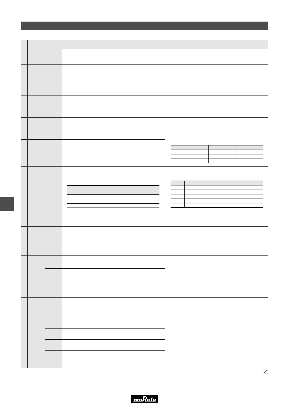
Specifications and Test Methods
C02E.pdf
05.12.14
12
No. Test Method
1
Item
Operating
Temperature
Range
R6 : Y55 to W85°C
R7, C7 : Y55 to W125°C
Specifications
The rated voltage is defined as the maximum voltage which
may be applied continuously to the capacitor.
Rated Voltage
2
See the previous pages.
When AC voltage is superimposed on DC voltage, V
whichever is larger, should be maintained within the rated
voltage range.
Appearance
3
Dimensions
4
No defects or abnormalities
Within the specified dimension
Visual inspection
Using calipers
No failure should be observed when 250% of the rated voltage
Dielectric Strength
5
No defects or abnormalities
is applied between the terminations for 1 to 5 seconds,
provided the charge/discharge current is less than 50mA.
Insulation
6
Resistance
7
Capacitance
More than 10,000MΩ or 500Ω · F
(Whichever is smaller)
Within the specified tolerance
The insulation resistance should be measured with a DC voltage
not exceeding the rated voltage at 25°C and 75%RH max. and
within 2 minutes of charging.
The capacitance/D.F. should be measured at 25°C at the
frequency and voltage shown in the table.
Dissipation Factor
8
(D.F.)
W.V.: 25V min.; 0.025 max.
W.V.: 16V max.; 0.035 max. *1
Capacitance
CV10µF (10V min.)
CV10µF (6.3V max.)
C>10µF
Frequency Voltage
1T0.1kHz
1T0.1kHz
120T24kHz
The capacitance change should be measured after 5 min. at
each specified temperature stage.
Capacitance
Temperature
9
Characteristics
Char.
R6
R7
C7
Temp. Range
(°C)
Y55 to +85
Y55 to +125
Y55 to +125
Reference
Temp.
25°C
25°C
25°C
Cap.Change
Within T15%
Within T15%
Within T22%
Step
1
2
3
4
5
Temperature (°C)
25T2
Y55T3
25T2
125T3
25T2
P-P
or V
1.0T0.2Vrms
0.5T0.1Vrms
0.5T0.1Vrms
O-P
,
Adhesive Strength
10
of Termination
Vibration
11
Resistance
Solderability of
12
Termination
Resistance
to Soldering
13
Heat
Appearance
Capacitance
D.F.
Appearance
Capacitance
Change
D.F.
I.R.
Dielectric
Strength
No removal of the terminations or other defect should occur.
No defects or abnormalities
Within the specified tolerance
W.V.: 25V min.; 0.025 max.
W.V.: 16V max.; 0.035 max. *1
75% of the terminations are to be soldered evenly
and continuously.
No marking defects
Within T7.5%
W.V.: 25V min.; 0.025 max.
W.V.: 16V max.; 0.035 max. *1
More than 10,000MΩ or 500Ω · F (Whichever is smaller)
No failure
The ranges of capacitance change compared with the 25°C
value over the temperature ranges shown in the table should
be within the specified ranges.
Solder the capacitor to the test jig (glass epoxy board) using a
eutectic solder. Then apply 5N force in parallel with the test jig
for 10T1 sec. The soldering should be done either with an iron
or using the reflow method and should be conducted with care
so that the soldering is uniform and free of defects such as heat
shock.
Solder the capacitor to the test jig (glass epoxy board) in
the same manner and under the same conditions as (10). The
capacitor should be subjected to a simple harmonic motion
having a total amplitude of 1.5mm, the frequency being varied
uniformly between the approximate limits of 10 and 55Hz. The
frequency range, from 10 to 55Hz and return to 10Hz, should
be traversed in approximately 1 minute. This motion should be
applied for a period of 2 hours in each 3 mutually perpendicular
directions (total of 6 hours).
Immerse the capacitor in a solution of ethanol (JIS-K-8101) and
rosin (JIS-K-5902) (25% rosin in weight proportion). Preheat at
80 to 120°C for 10 to 30 seconds. After preheating, immerse in
eutectic solder solution for 2T0.5 seconds at 230T5°C, or
Sn-3.0Ag-0.5Cu solder solution for 2T0.5 seconds at 245T5°C.
Preheat the capacitor at 120 to 150°C for 1 minute. Immerse
the capacitor in a eutectic solder or Sn-3.0Ag-0.5Cu solder
solution at 270T5°C for 10T0.5 seconds solution at 270T5°C
for 10T0.5 seconds. Let sit at room temperature for 48T4
hours, then measure.
• Initial measurement.
Perform a heat treatment at 150 °C for one hour and then
+0
–10
let sit for 48T4 hours at room temperature. Perform the initial
measurement.
70
Page 8
• This PDF catalog is downloaded from the website of Murata Manufacturing co., ltd. Therefore, it’s specifications are subject to change or our products in it may be discontinued without advance notice. Please check with our
!Note
• Please read rating and !CAUTION (for storage, operating, rating, soldering, mounting and handling) in this catalog to prevent smoking and/or burning, etc.
!Note
sales representatives or product engineers before ordering.
• This catalog has only typical specifications because there is no space for detailed specifications. Therefore, please approve our product specifications or transact the approval sheet for product specifications before ordering.
• This PDF catalog has only typical specifications because there is no space for detailed specifications. Therefore, please approve our product specifications or transact the approval sheet for product specifications before ordering.
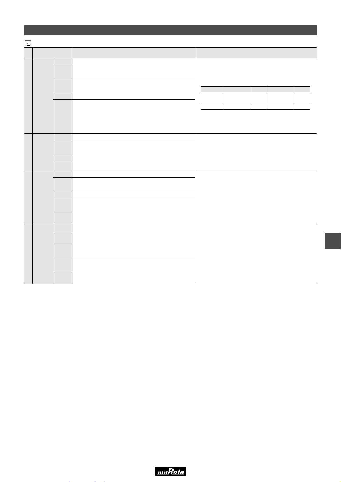
Specifications and Test Methods
Continued from the preceding page.
ItemNo. Test Method
No marking defects
Within T7.5% *1
W.V.: 25V min.; 0.025 max.
W.V.: 16V max.; 0.035 max. *1
More than 10,000MΩ or 500Ω · F (Whichever is smaller)
No failure
No marking defects
Within T12.5% *1
0.05 max. *1
More than 1,000MΩ or 50Ω · F (Whichever is smaller)
No marking defects
Within T12.5% *1
0.05 max. *1
More than 500MΩ or 25Ω · F *1
(Whichever is smaller)
No failure
No marking defects
Within T12.5% *1
W.V.: 25V min.; 0.04 max.
W.V.: 16V max.; 0.05 max. *1
More than 1,000MΩ or 50Ω · F *1
(Whichever is smaller)
No failure
Temperature
14
Cycle
Humidity
(Steady
15
State)
Humidity
16
Load
High
Temperature
17
Load
Appearance
Capacitance
Change
D.F.
I.R.
Dielectric
Strength
Appearance
Capacitance
Change
D.F.
I.R.
Appearance
Capacitance
Change
D.F.
I.R.
Dielectric
Strength
Appearance
Capacitance
Change
D.F.
I.R.
Dielectric
Strength
*1 : The ligure Indicates typical inspection.Please refer to individual specifications.
*2 : Some of the parts are applicable in rated voltageA150%. Please refer to individual specifications.
Specifications
Fix the capacitor to the supporting jig in the same manner and
under the same conditions as (10).
Perform the five cycles according to the four heat treatments
listed in the following table. Let sit for 48T4 hours at room
temperature, then measure.
Step 1 2 3 4
Min. Operating
Temp. (°C)
Time (min.)
Temp.
30T3
+0
–3
• Initial measurement.
Perform a heat treatment at 150 °C for one hour and then
Room
Temp.
2 to 3
+0
–10
Max. Operating
Temp.
30T3
let sit for 48T4 hours at room temperature. Perform the initial
measurement.
Sit the capacitor at 40T2°C and 90 to 95% humidity for 500T12
hours. Remove and let sit for 48T4 hours at room temperature,
then measure.
Apply the rated voltage at 40T2°C and 90 to 95% humidity for
500T12 hours. Remove and let sit for 48T4 hours at room
temperature, then measure. The charge/discharge current is
less than 50mA.
Apply 200% of the rated voltage for 1000T12 hours at the
maximum operating temperature T3°C. Let sit for 48T4 hours
at room temperature, then measure. The charge/discharge
current is less than 50mA.
•Initial measurement.
Apply 200% (*2) of the rated DC voltage for one hour at the
maximum operating temperature T3°C. Remove and let sit for
48T4 hours at room temperature.
Perform initial measurement. (*1)
C02E.pdf
05.12.14
Room
+3
–0
Temp.
2 to 3
12
71
 Loading...